

Page 1
Application Note:
Interfacing non-standard cameras to Matrox Pulsar
JAI CV-M30 October 29, 1996
Camera
Interface
Overview
Camera
Interface
Details
• 768 x 494 x 8-bit
• Analog video output
• Interlaced or non-interlaced
• Internal composite sync
• Internal exposure control
• Modes of operations: continuous mode (normal or double speed), continuous partial
scanning mode (1/2 and 1/3 both at normal or double speed) and asynchronous mode
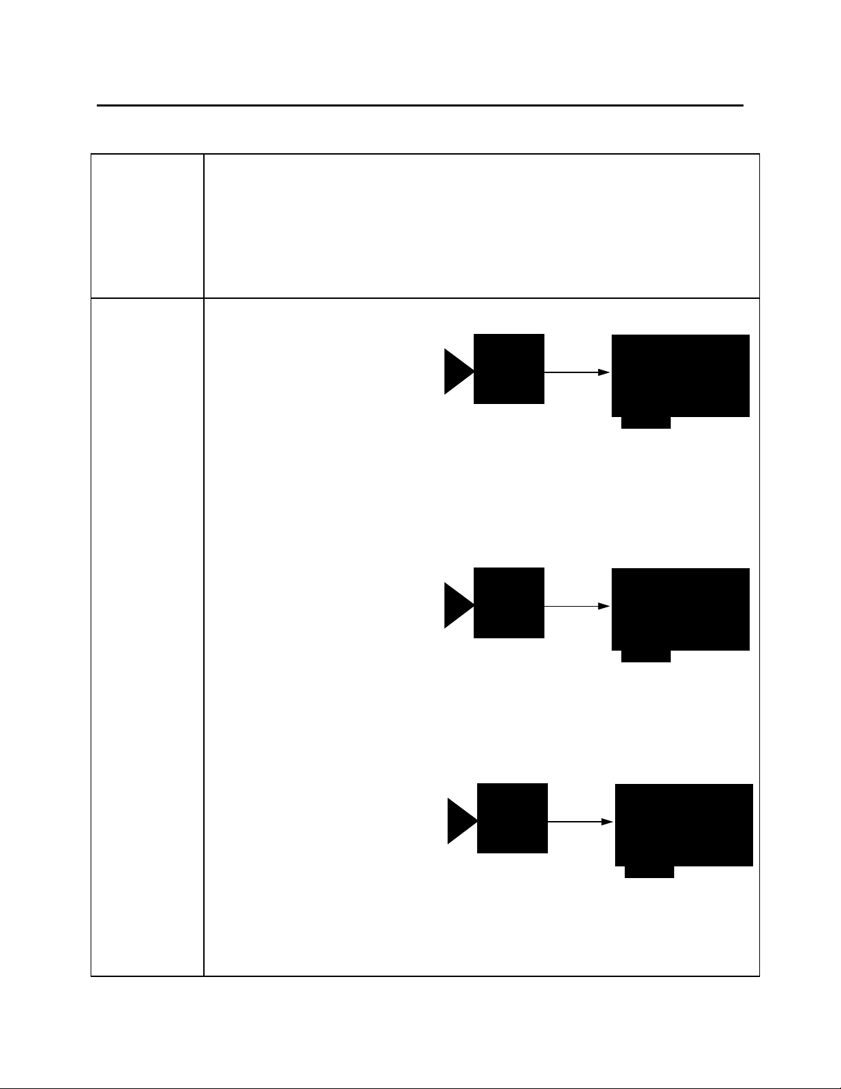
1. Continuous mode (Double speed, interlaced)
CV-M30
• 752 x 484 x 8-bit @60 fps
• Interlaced
• Analog (composite) video output
• Internal exposure control (normal shutter mode)
• Double speed mode
• Continuous video
• DCF used: CVM30S.DCF
JAI
Video
Matrox
Pulsar
2. Continuous mode (Double speed, non-interlaced)
JAI
• 752 x 240 x 8-bit @120 fps
• Non-interlaced
• Analog (composite) video output
• Internal exposure control (normal shutter mode)
• Double speed mode
• Continuous video
• DCF used: CVM30NS.DCF
CV-M30
3. Continuous mode (Normal speed, interlaced)
JAI
CV-M30
• 752 x 484 x 8-bit @30 fps
• Interlaced
• Analog (composite) video output
• Internal exposure control (normal shutter mode)
• Normal speed mode
• Continuous video
• DCF used: CVM30.DCF
Video
Video
Matrox
Pulsar
Matrox
Pulsar
Page 2
Application Note:
Interfacing non-standard cameras to Matrox Pulsar
JAI CV-M30 October 29, 1996
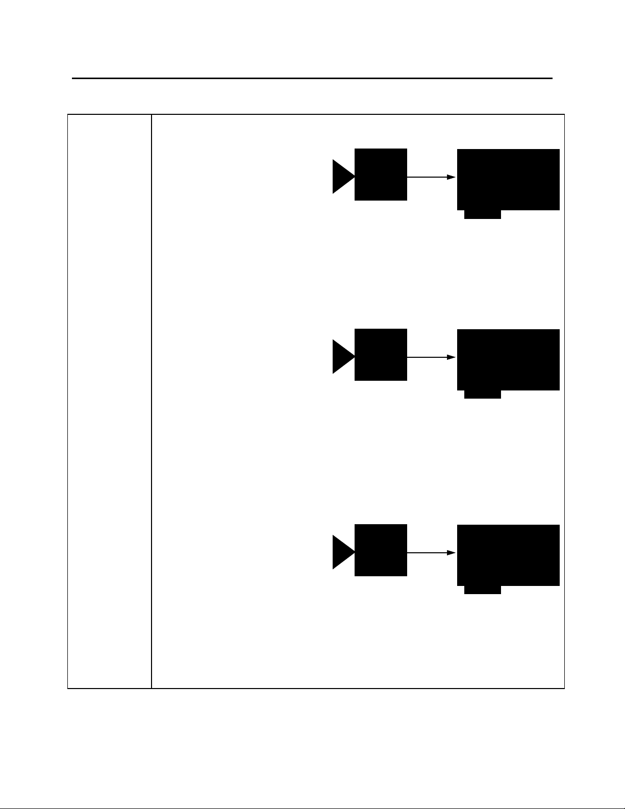
4. Continuous mode (Normal speed, non-interlaced)
JAI
CV-M30
• 752 x 240 x 8-bit @60 fps
• Analog (composite) video output
• Non-interlaced
• Internal exposure control (normal shutter mode)
• Normal speed mode
• Continuous video
• DCF used: CVM30N.DCF
Video
5. Continuous partial scanning (1/2) mode (Normal speed)
JAI
CV-M30
• 752 x 110 x 8-bit @120 fps
• Analog (composite) video output
• Non-interlaced
• Internal exposure control (normal shutter mode)
• Normal speed mode
• Partial scan ½
• Continuous video
• DCF used: CVM30P1.DCF
Video
Matrox
Pulsar
Matrox
Pulsar
6. Continuous partial scanning (1/3) mode (Normal speed)
JAI
CV-M30
• 752 x 66 x 8-bit @180 fps
• Analog (composite) video output
• Non-interlaced
• Internal exposure control (normal shutter mode)
• Normal speed mode
• Partial scan 1/3
• Continuous video
• DCF used: CVM30P2.DCF
Video
PUL-CID-030
Matrox
Pulsar
2
Page 3

Application Note:
Interfacing non-standard cameras to Matrox Pulsar
JAI CV-M30 October 29, 1996
7. Continuous partial scanning (1/2) mode (Double speed)
• 752 x 110 x 8-bit @240 fps
• Non-interlaced
• Analog (composite) video output
• Internal exposure control (normal shutter mode)
• Double speed mode
• Partial scan ½
• Continuous video
• DCF used: CVM30P3.DCF
CV-M30
JAI
Video
8. Continuous partial scanning (1/3) mode (Double speed)
JAI
CV-M30
• 752 x 66 x 8-bit @360 fps
• Non-interlaced
• Analog (composite) video output
• Internal exposure control (normal shutter mode)
• Double speed mode
• Partial scan 1/3
• Continuous video
• DCF used: CVM30P4.DCF
Video
Matrox
Pulsar
Matrox
Pulsar
9. Asynchronous reset mode (trigger mode)
Video
JAI
JAI
CV-M30
CV-M30
• 752 x 240 x 8-bit
• Analog video output
• Non-interlaced
• Internal exposure control with times ranging from 1/60 second to 1/1000 second
• Asynchronous reset mode
• Normal speed mode
• DCF used: CVM30A.DCF
trigger
Wen (vsync)
TTL external trigger
PUL-CID-030
Matrox Pulsar
Matrox
(with PLS-TTL-CABLE)
Pulsar
3
Page 4

Application Note:
Interfacing non-standard cameras to Matrox Pulsar
JAI CV-M30 October 29, 1996
Cabling
Requirements
1. Continuous Modes 1 through 8
• IMG-7W2-TO-1BNC required
• Video input BNC of IMG-7W2-TO 1BNC cable should be connected to VIDEO
OUT BNC connector of camera
• The switches on the rear panel of the camera must be correctly configured, see
SPECIAL CONSIDERATIONS for each mode’s switch configuration
2. Mode 9 Asynchronous reset mode (trigger mode)
• IMG-7W2-TO-5BNC cable and PLS-TTL-CABLE required
• Video input of BNC of IMG-7W2-TO-5BNC cable should be connected to VIDEO
OUT BNC connector of camera
• The switches on the rear panel of the camera must be correctly configured, see
SPECIAL CONSIDERATIONS for this mode’s switch configuration
• The connections between the DB-37 connector of the PLS-TTL-CABLE and the 6-
pin male HIROSE connector of the camera are as follow:
PLS-TTL-CABLE JAI CV-M30
(DB-37 connector) (6-pin male HIROSE
connector)
Pin name Pin no. Pin name
Pin no.
TTL-EXPOSURE1 9 → TRIGGER 5
TTL-VSYNC 11 ← VALID (WEN) 6
GROUND 6 GROUND 3
Special
Considerations
PUL-CID-030
• TTL external trigger source should be connected to the TTL trigger input of IMG-
7W2-TO-5BNC cable
Switch settings (switches on rear panel of camera) for all 9 modes
OFF ON
•
•
•
•
•
•
•
1. continuous mode
(double speed, interlaced)
ED2 shutter speed
1
ED1 shutter speed
2
ED0 shutter speed
3
LM2 scanning mode
4
RM1 scanning speed
5
LM1 scanning mode
6
TRSW reset mode
7
OFF ON
•
•
•
•
•
•
2. continuous mode
(double speed, non-interlaced)
ED2 shutter speed
1
ED1 shutter speed
2
ED0 shutter speed
3
LM2 scanning mode
4
RM1 scanning speed
5
LM1 scanning mode
6
•
TRSW reset mode
7
4
Page 5

Application Note:
•
Interfacing non-standard cameras to Matrox Pulsar
JAI CV-M30 October 29, 1996
3. continuous mode
(normal speed, interlaced)
OFF ON
•
•
•
•
•
•
•
ED2 shutter speed
1
ED1 shutter speed
2
ED0 shutter speed
3
LM2 scanning mode
4
RM1 scanning speed
5
LM1 scanning mode
6
TRSW reset mode
7
5. continuous partial scanning (1/2) mode
(normal speed)
OFF ON
•
•
•
•
•
•
•
ED2 shutter speed
1
ED1 shutter speed
2
ED0 shutter speed
3
LM2 scanning mode
4
RM1 scanning speed
5
LM1 scanning mode
6
TRSW reset mode
7
7. continuous partial scanning (1/2) mode
(double speed)
OFF ON
•
•
•
•
•
•
•
ED2 shutter speed
1
ED1 shutter speed
2
ED0 shutter speed
3
LM2 scanning mode
4
RM1 scanning speed
5
LM1 scanning mode
6
TRSW reset mode
7
9. asynchronous reset mode
4. continuous mode
(normal speed, non-interlaced)
OFF ON
•
•
•
•
•
•
•
ED2 shutter speed
1
ED1 shutter speed
2
ED0 shutter speed
3
LM2 scanning mode
4
RM1 scanning speed
5
LM1 scanning mode
6
TRSW reset mode
7
6. continuous partial scanning (1/3) mode
(normal speed)
OFF ON
•
•
•
•
•
•
•
ED2 shutter speed
1
ED1 shutter speed
2
ED0 shutter speed
3
LM2 scanning mode
4
RM1 scanning speed
5
LM1 scanning mode
6
TRSW reset mode
7
8. continuous partial scanning (1/3) mode
(double speed)
OFF ON
•
•
•
•
•
•
•
ED2 shutter speed
1
ED1 shutter speed
2
ED0 shutter speed
3
LM2 scanning mode
4
RM1 scanning speed
5
LM1 scanning mode
6
TRSW reset mode
7
OFF ON
•
•
•
•
•
•
•
PUL-CID-030
ED2 shutter speed
1
ED1 shutter speed
2
ED0 shutter speed
3
LM2 scanning mode
4
RM1 scanning speed
5
LM1 scanning mode
6
TRSW reset mode
7
AGC AGC mode
8
The internal exposure control can
be changed by the first 3
switches
5
Page 6

Application Note:
Interfacing non-standard cameras to Matrox Pulsar
JAI CV-M30 October 29, 1996
Asynchronous reset mode (trigger mode)
• The shutter mode is selected by using the SW1 switches on the rear of the camera.
• In asynchronous reset mode, the switch RM1 should always be set to the ON position
since this mode can only work in normal mode.
• Once in asynchronous reset mode (by setting the TRSW switch to ON), the
exposure time is set using switches #1, #2 and #3 on the rear panel of the camera. In
“normal speed” mode, exposure times range from (1/60)s to (1/10 000)s. In “double
speed” mode, exposure times range from (1/120)s to (1/20 000)s. Consult the CVM30 manual as to the positions of these three switches in addition to the
corresponding exposure times
• Once it has received the external signal to trigger, the Pulsar sends a TTL exposure
signal to the camera. The camera awaits the falling edge of the signal, at which point
it initiates exposure. The minimum duration of the active low portion of an exposure
pulse must be 2µs
• Contact your local sales representative or Matrox Sales Office, or contact Matrox
Imaging Applications at 514-822-6061 for assistance (if required).
The DCF(s) mentioned in this application note can be found on the MIL and MIL-Lite CD, or our FTP site (ftp.matrox.com). The information furnished by
Matrox Electronics System, Ltd. is believed to be accurate and reliable. Please verify all interface connections with camera documentation or manual.
Contact your local sales representative or Matrox Sales office or Matrox Imaging Applications at 514-822-6061 for assistance.
CorporateCorporate
Headquarters:Headquarters:
Canada and U.S.A.Canada and U.S.A.
Matrox ElectronicMatrox Electronic
Systems Ltd.Systems Ltd.
1055 St.Regis Blvd.
Dorval, Quebec, Canada
H9P 2T4
Tel: (514) 685-7230
Fax: (514) 822-6273
PUL-CID-030
Sales Offices:Sales Offices:
U.K.U.K.
Matrox (UK) Ltd.Matrox (UK) Ltd.
Sefton Park, Stoke Poges
Buckinghamshire
U.K. SL2 4JS
Tel: +44 (0) 1753 665500
Fax: +44 (0) 1753
665599
FranceFrance
Matrox France SARLMatrox France SARL
2, rue de la Couture,
Silic 225
94528 Rungis Cedex
Tel: (0) 1 45-60-62-00
Fax: (0) 1 45-60-62-05
GermanyGermany
Matrox GmbHMatrox GmbH
Inselkammerstr.8
D-82008
Unterhaching
Germany
Tel: 089/614 4740
Fax: 089/614 9743
Asia PacificAsia Pacific
Matrox Asia LiaisonMatrox Asia Liaison
OfficeOffice
Rm. 1901, 19/F, Workington
Tower,
78 Bonham Strand E.,
Sheung Wan, Hong Kong.
Tel: 852.2877.5387
Fax: 852.2537.9530
6
 Loading...