

Page 1
Application Note:
Interfacing non-standard cameras to Matrox Pulsar
Toshiba IK-543 April 12, 1996
Camera
Interface
Overview
Camera
Interface
Details
• 640 x 492 (max) x 8-bit @ 30fps or 640 x 240 x 8-bit @ 60fps
• analog video output
• interlaced or non-interlaced
• internal sync
• internal exposure control
• 6 modes: continuous mode (3 submodes), asynchronous reset mode (3 submodes)
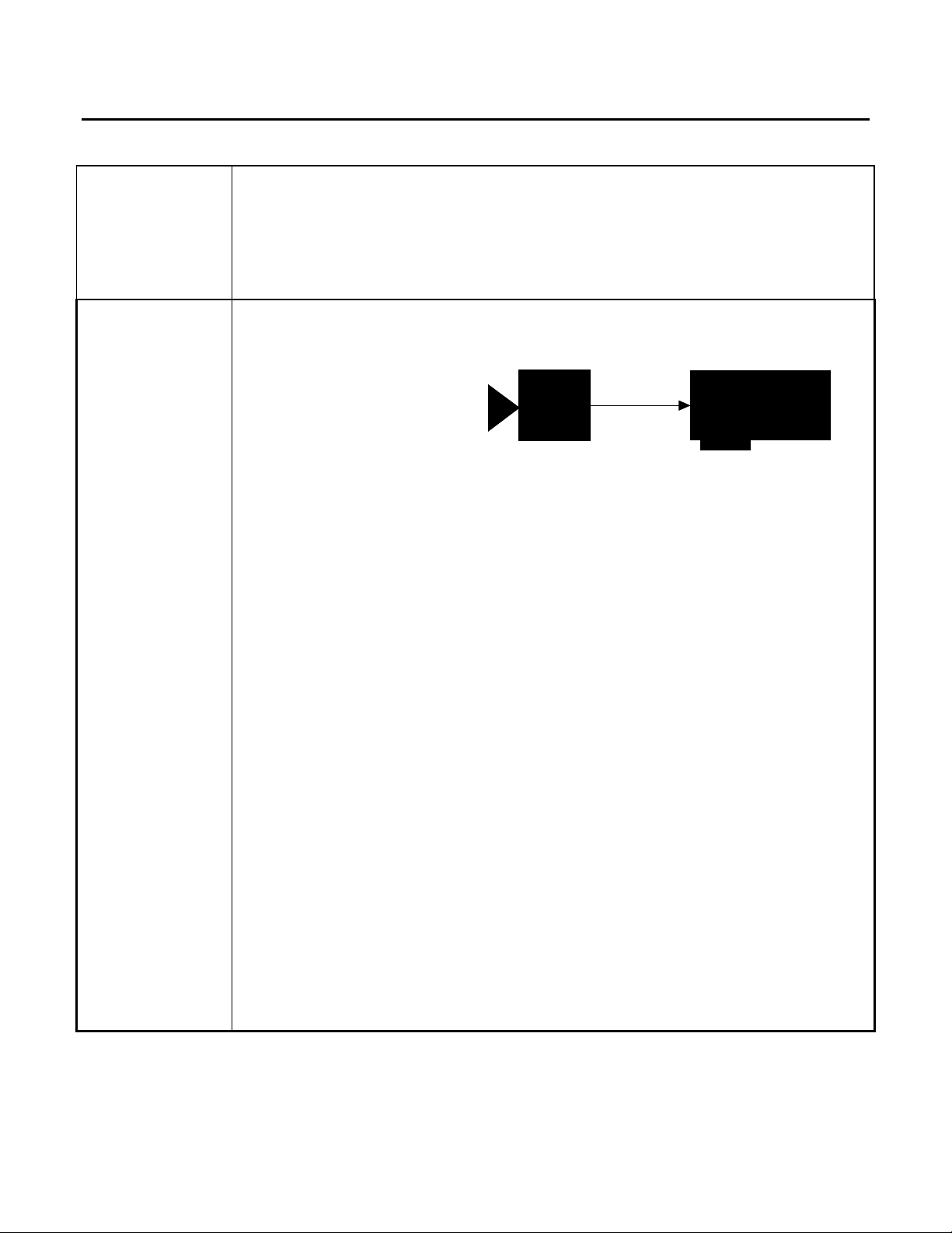
1. Continuous mode
Toshiba
IK-543
Video
Matrox Pulsar
Submode 1:
• 640 x 484 x 8-bit @ 30fps
• analog (composite) video output
• interlaced
• continuous video
• internal exposure control with times ranging from (1/30)s to (1/50000)s
• DCF used: IK543.DCF
Submode 2:
• 640 x 492 x 8-bit @ 30fps
• analog (composite) video output
• non-interlaced
• continuous video
• internal exposure control with times ranging from (1/60)s to (1/50000)s
• DCF used: IK543N.DCF
Submode 3:
• 640 x 240 x 8-bit @ 60fps
• analog (composite) video output
• non-interlaced
• continuous video
• internal exposure control with times ranging from (1/30)s to (1/50000)s
• DCF used: IK543N2.DCF
Page 2
Application Note:
Interfacing non-standard cameras to Matrox Pulsar
Toshiba IK-543 April 12, 1996
Camera
Interface
Details
Continued
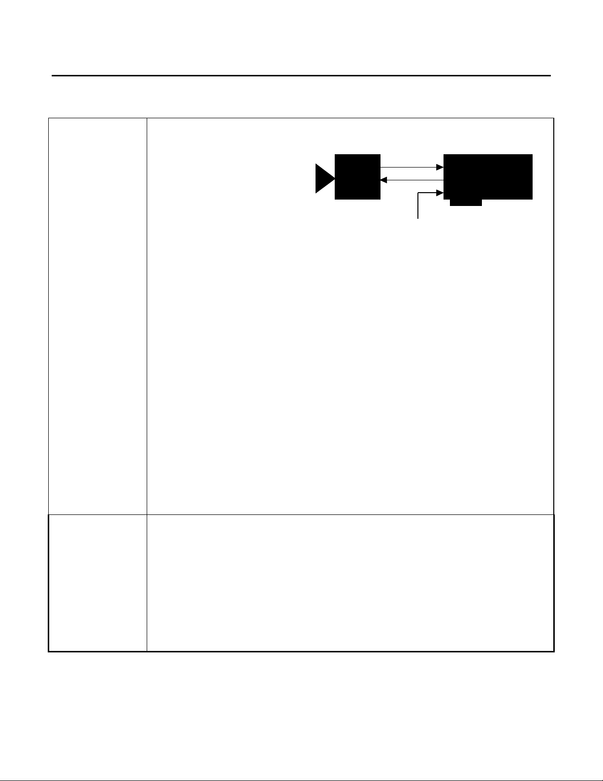
2. Asynchronous reset mode
Toshiba
IK-543
Submode 1:
• 640 x 484 x 8-bit @ 30fps (max)
• analog (composite) video output
• interlaced
• internal exposure control with times ranging from (1/60)s to (1/50000)s
• DCF used: IK543A.DCF
Video
TRIGGER IN
TTL external trigger
Submode 2:
• 640 x 492 x 8-bit @ 30fps (max)
• analog (composite) video output
• non-interlaced
• internal exposure control with times ranging from (1/60)s to (1/50000)s
• DCF used: IK543AN.DCF
Matrox Pulsar
(with PLS-TTL-CABLE)
Cabling
Requirements
Submode 3:
• 640 x 240 x 8-bit @ 60fps (max)
• analog (composite) video output
• non-interlaced
• internal exposure control with times ranging from (1/60)s to (1/50000)s
• DCF used: IK543AN2.DCF
1. Continuous mode
• IMG-7W2-TO-1BNC cable required
• video input BNC of IMG-7W2-TO-1BNC cable should be connected to VIDEO OUT
BNC connector of camera
Submode 1:
• the SELECT switch is set to 1/30I and the exposure time is selected using the SHUTTER
switch; these two switches are located on the rear of the camera. The S201 internal
switches of the camera are all set to OFF
PUL-CID-016 2
Page 3

Application Note:
Interfacing non-standard cameras to Matrox Pulsar
Toshiba IK-543 April 12, 1996
Cabling
Requirements
Continued
Submode 2:
• the SELECT switch is set to 1/30N and the exposure time is selected using the
SHUTTER switch; these two switches are located on the rear of the camera. The S201
internal switches of the camera are all set to OFF
Submode 3:
• the SELECT switch is set to 1/60N and the exposure time is selected using the
SHUTTER switch; these two switches are located on the rear of the camera. The S201
internal switches of the camera are all set to OFF
2. Asynchronous reset mode
• IMG-7W2-TO-5BNC cable and PLS-TTL-CABLE required
• video input BNC of IMG-7W2-TO-5BNC cable should be connected to VIDEO OUT
BNC connector of camera
• the connections between the DB-37 connector of the PLS-TTL-CABLE and the 12-pin
DC IN/SYNC connector of the camera are as follows:
PLS-TTL-CABLE Toshiba IK-543
(DB-37 connector) (12-pin DC IN/SYNC connector)
Pin name Pin no. Pin name Pin no.
TTL_EXPOSURE1 9 → TRIGGER IN 11
GROUND 7 TRIGGER IN (GND) 12
• TTL external trigger source should be connected to the TTL Trigger Input of the IMG-
7W2-TO-5BNC cable
Submode 1:
• the SELECT switch is set to 1/30I and the exposure time is selected using the
SHUTTER switch; these two switches are located on the rear of the camera. The
internal switches of the camera are set in the following way: S201/1 = OFF; S201/2 =
ON; S201/3 = OFF; S201/4 = ON; S201/5 = OFF; S201/6 = OFF; S202 = TTL
Submode 2:
• the SELECT switch is set to 1/30N and the exposure time is selected using the
SHUTTER switch; these two switches are located on the rear of the camera. The
internal switches of the camera are set as in asynchronous reset mode: submode 1
Submode 3:
• the SELECT switch is set to 1/60N and the exposure time is selected using the
SHUTTER switch; these two switches are located on the rear of the camera. The
internal switches of the camera are set as in asynchronous reset mode: submode 1
PUL-CID-016 3
Page 4

Application Note:
Interfacing non-standard cameras to Matrox Pulsar
Toshiba IK-543 April 12, 1996
Special
Considerations
Continued
Continuous and asynchronous reset modes
• the exposure time is selected using the SHUTTER switch on the rear panel of the camera.
The positions on the SHUTTER switch correspond to the following exposure times:
SHUTTER switch exposure SHUTTER switch exposure
position time (s) position time (s)
0 1/60 9 1/4000
1 1/100 A 1/6000
2 1/125 B 1/8000
3 1/250 C 1/10000
4 1/500 D 1/30000
5 1/1000 E 1/50000
6 1/1500 F for use with
7 1/2000 2 pulse trigger
8 1/3000 camera mode
• to select an exposure time of (1/30)s, set the SHUTTER switch on the rear of the camera
to 0 and set switch S201/6 located inside the camera to ON
• the camera manual states that in the 1/60N mode, the camera provides the ODD fields of
the output signal on VIDEO1 of the 12-pin connector and the EVEN fields on VIDEO2;
however, this was not the case with the camera we tested. Instead, both VIDEO1 and
VIDEO2 were alternating between ODD and EVEN fields, i.e., if the output on VIDEO1
was ODD-EVEN-ODD then the output on VIDEO2 was EVEN-ODD-EVEN (the Pulsar
can grab from only one of these two outputs at a time). Although we have received
confirmation that the camera currently does operate in this way, we are told that its
functionality will be altered to match the one described in the manual. This revised
functionality will cause the DCFs for the 1/60N camera mode to require modification.
Please contact Matrox Imaging Applications at (514) 969-6061 in order to obtain
assistance in making these modifications
• another modification that we are told will be made to the camera concerns the polarity of
the first field to be output by the camera when in 1/30I mode. Currently the first field that
is output is said to be ODD. After modification, the first field to be output will be EVEN.
Once this alteration is made there will be a problem with the setting of the field polarity in
the DCFs that will manifest itself in one or two ways: the jagged appearance of diagonal
lines and/or the absence of either all the odd lines or all the even lines in the acquired
image. These problems can be solved by modifying the DCFs at the hardware register
level. A hardware register editor is provided by running Intellicam with the
-hwreg option (specifically by running INTELCAM -hwreg). An additional menu item,
“HW REGISTER EDITOR”, appears on the main menu screen; select this option using the
cursor and the enter key. If diagonal lines appear jagged in the acquired image, the
FLDPOL bit of the 16-bit PSG_POLCTL register must be changed. Use the arrow keys to
find the PSG_POLCTL register and once there, use the F2 key to view the individual bits
of this register.
PUL-CID-016 4
Page 5

Application Note:
Interfacing non-standard cameras to Matrox Pulsar
Toshiba IK-543 April 12, 1996
Special
Considerations
Continued
Again use the arrow keys to find the FLDPOL bit of the PSG_POLCTL register and once
this bit is found, use the F2 key to view the options; use the arrow keys and the enter key
to make a selection. When operating the camera in continuous mode, only the FLDPOL
bit need be changed to correct for a field inversion. If every second line of the image is
missing, causing the image to appear darker, either the odd lines or the even lines are
missing from the frame. If this is the case, the FLDSEL bit of the 16-bit PSG_EXTCTL
register must be changed. Use the arrow keys to find the PSG_EXTCTL register and once
there, use the F2 key to view the individual bits of this register. Use the arrow keys to find
the FLDSEL bit of the PSG_EXTCTL register and once this bit is found, use the F2 key
to view the options; use the arrow keys and the enter key to make a selection. In
asychronous reset mode, both the FLDPOL bit and the FLDSEL bit will have to be
changed to correct for a field inversion. If assistance is required in making any necessary
modifications to the DCFs, please contact Matrox Imaging Applications at (514) 8226061
• for the camera we tested, we found that in asynchronous reset mode the connection from
the TTL_EXPOSURE1 output of the PLS-TTL-CABLE to the TRIGGER IN input of the
camera had to be made before power was supplied to the camera or the camera would not
reset on the trigger
• in addition to the DCFs, PSG FPGA version 3.53 or newer is required; if this version is
not on your release of the MIL driver for Pulsar, the newest version can be found on the
BBS or at the FTP site
The DCF(s) mentioned in this application note can be found on the MIL and MIL-Lite CD, or our FTP site (ftp.matrox.com). The information furnished by
Matrox Electronics System, Ltd. is believed to be accurate and reliable. Please verify all interface connections with camera documentation or manual.
Contact your local sales representative or Matrox Sales office or Matrox Imaging Applications at 514-822-6061 for assistance.
CorporateCorporate
Headquarters:Headquarters:
Canada and U.S.A.Canada and U.S.A.
Matrox ElectronicMatrox Electronic
Systems Ltd.Systems Ltd.
1055 St.Regis Blvd.
Dorval, Quebec, Canada
H9P 2T4
Tel: (514) 685-7230
Fax: (514) 822-6273
Sales Offices:Sales Offices:
U.K.U.K.
Matrox (UK) Ltd.Matrox (UK) Ltd.
Sefton Park, Stoke Poges
Buckinghamshire
U.K. SL2 4JS
Tel: +44 (0) 1753 665500
Fax: +44 (0) 1753
665599
FranceFrance
Matrox France SARLMatrox France SARL
2, rue de la Couture,
Silic 225
94528 Rungis Cedex
Tel: (0) 1 45-60-62-00
Fax: (0) 1 45-60-62-05
GermanyGermany
Matrox GmbHMatrox GmbH
Inselkammerstr.8
D-82008
Unterhaching
Germany
Tel: 089/614 4740
Fax: 089/614 9743
Asia PacificAsia Pacific
Matrox Asia LiaisonMatrox Asia Liaison
OfficeOffice
Rm. 1901, 19/F, Workington
Tower,
78 Bonham Strand E.,
Sheung Wan, Hong Kong.
Tel: 852.2877.5387
Fax: 852.2537.9530
PUL-CID-016 5
 Loading...