

Page 1
ATA Hard Drive
Installation
Guide
P/N: 20186800/A
Page 2

. . . . . . . . . . . . . . . . . . . . . . . . 3
. . . . . . . . . . . . . . . . . . . . 15
. . . . . . . . . . . . . . . . . . . . . . 30
Page 3

Page 4
Getting Started 1
1
Getting Started
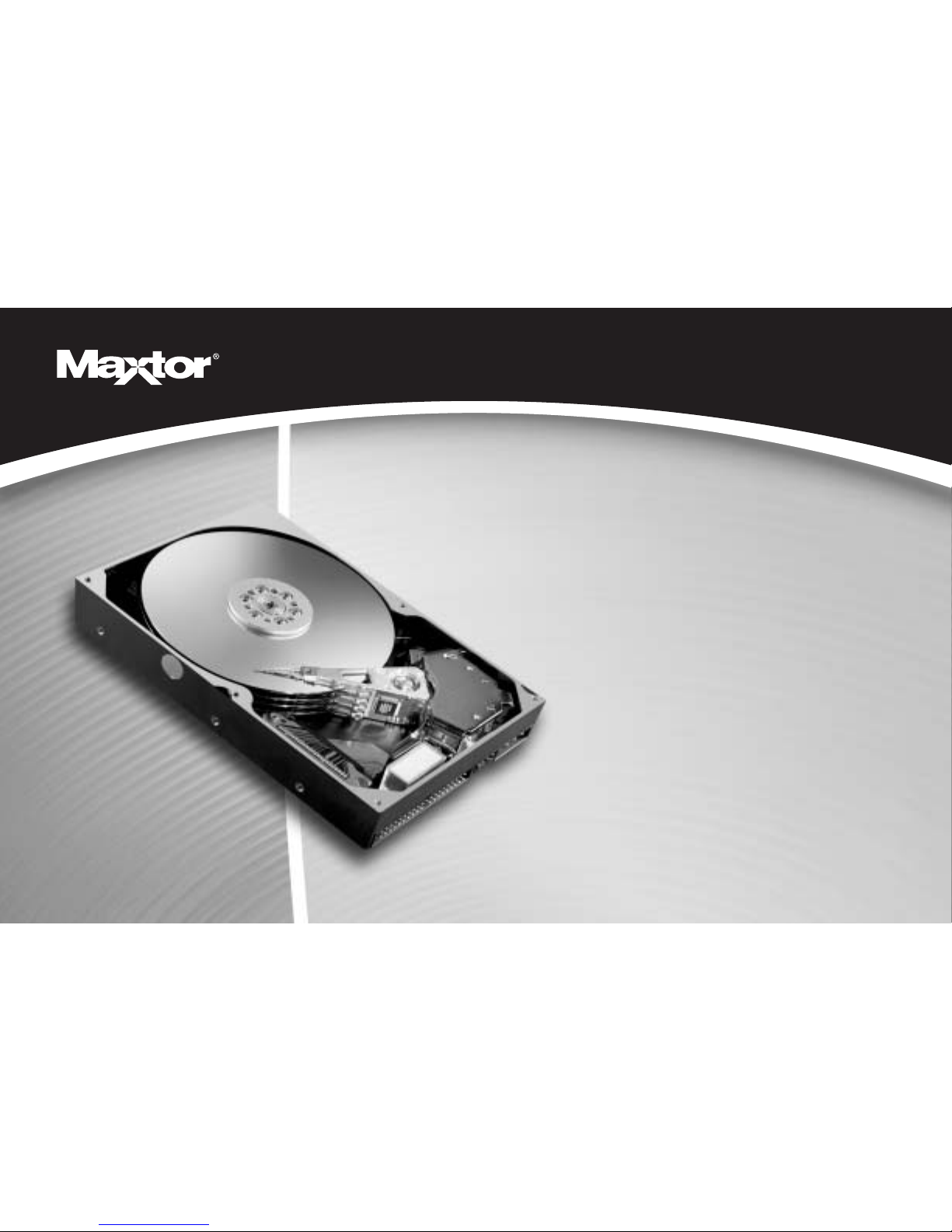
Thank you for selecting a Maxtor hard drive storage product. This installation guide will lead
you through the installation of your hard drive.
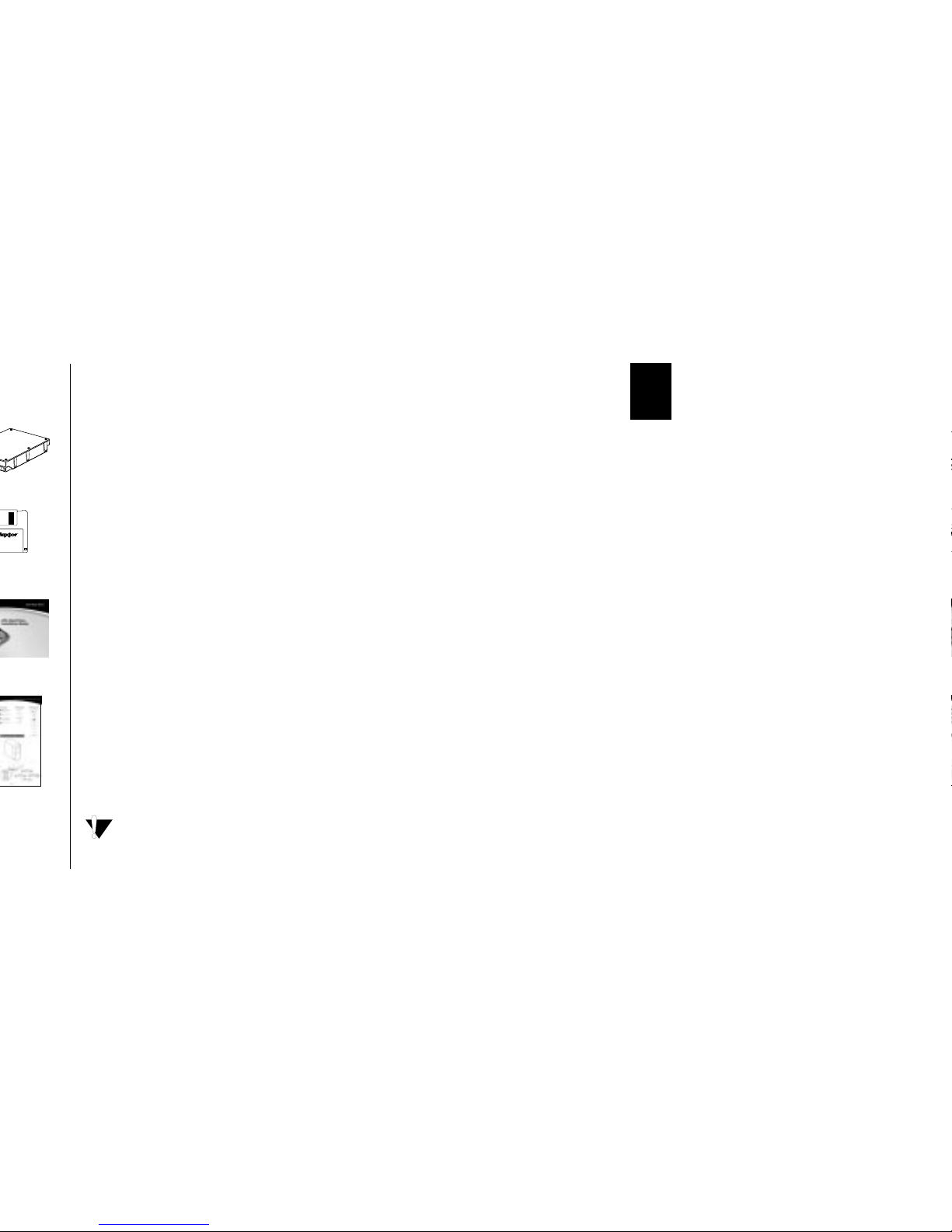
The Maxtor Hard Drive Retail Kit includes the components shown in Figure 1. Your
computer may need some or all of these parts to complete the installation. You will also need
the tools shown in Figure 2 on page 2 to install the hard drive in your computer.
Handling the Hard Drive
Your hard drive should be handled with care during unpacking and installation. Damage to
hard drives is typically caused by rough handling, shock, vibration, or electrostatic discharge
(ESD). Be aware of the following precautions when unpacking and handling your hard drive:
• Save the packing materials in case you need to return your hard drive.
• Allow the hard drive to reach room temperature before opening the anti-static bag.
• Handle the hard drive by its sides. Do not touch the circuit board electronics on the bottom
of the hard drive.
• Do not connect or disconnect any hard drive cables when the system is powered on.
• Do not drop, jar, or bump the hard drive.
Operating System Requirements
A full version of your operating system is required to install a new hard drive.
Windows 98, ME, NT, 2000 and XP (before SP1), and Mac OS operating systems do not
properly support the full capacity of an internal hard drive larger than 137 GB. See
“Formatting the Hard Drive” on page 15 for more information.
Page 5
an Ultra/ATA PCI adapter card, be sure that your
™
Plus II installation software, rather
System Manual
System User Manual
Operating System
CD and/or Boot Disk
Phillips Screwdriver
Small Needle-Nose Pliers
Figure 2. Required Tools
Page 6
Installing the Hard Drive 3
2
Installing the Hard Drive
This chapter describes how to physically install the hard drive in your computer. The
installation steps are as follows:
• Remove the system cover.
• Set the jumpers.
• Mount the hard drive in your computer.
• Attach the cables.
• Configure the BIOS (Windows-based systems only).
Removing the System Cover
For Macintosh systems, refer to the documentation that came with your system or go to
www.apple.com/support for information about opening your system case.
1.
Turn your computer off.
Leave the computer powered off and plugged into an electrical outlet to keep the
system grounded.
2.
Remove the cover from your system case.
Refer to your computer system user manual
for instructions on removing the cover, or obtain the services of a qualified installation
technician.
3.
Attach a grounding strap or touch a metal portion of your computer case.
This
will ground you to minimize the risk of exposing the hard drive to electrostatic discharge.
Page 7

Figure 4. A Jumper
Page 8

Installing the Hard Drive 5
2
Determining the Correct Jumper Setting
The correct jumper setting for your hard drive depends on your current system configuration
and how you want to use the new hard drive. The recommended jumper settings below will
work on many, but not all, systems.
• If you are building a new system, use the cable select setting on all ATA devices to make it
easier to configure your system.
• If you have an existing system, check the jumper settings on your current boot drive and
your CD-ROM drive. If these drives are using master/slave jumper settings, use the master/
slave jumper settings on your new hard drive. If your current boot drive and CD-ROM
drive are using the cable select setting, use cable select on the new hard drive.
Internal CD-ROM, DVD, Zip, and Jaz drives with an ATA interface are known as ATAPIcompliant devices. If the new hard drive is being attached to a cable to which an ATAPI
drive is already attached, you should configure the hard drive as master and the ATAPI
device as slave OR both devices as cable select, with the ATAPI device attached to the
gray connector on the ATA cable. To avoid potential issues with hard drive detection and
performance, Maxtor does not recommend attaching a hard drive as a slave on the same
cable as an ATAPI device. (For cable configuration, see “Existing System 3” on page 11.)
To determine your hard drive’s jumper style
1.
Remove the hard drive from its anti-static bag.
2.
Locate the jumper block on the back of hard drive.
The jumper block is located to
the right of the ATA connector on the hard drive. See Figure 5.
3.
Match the jumper block to jumper style A, B, or C shown in Figure 5. To
determine if you have jumper style C, look for model number D740X or D540X-4K on the
label located on the top of the hard drive.
"
Page 9
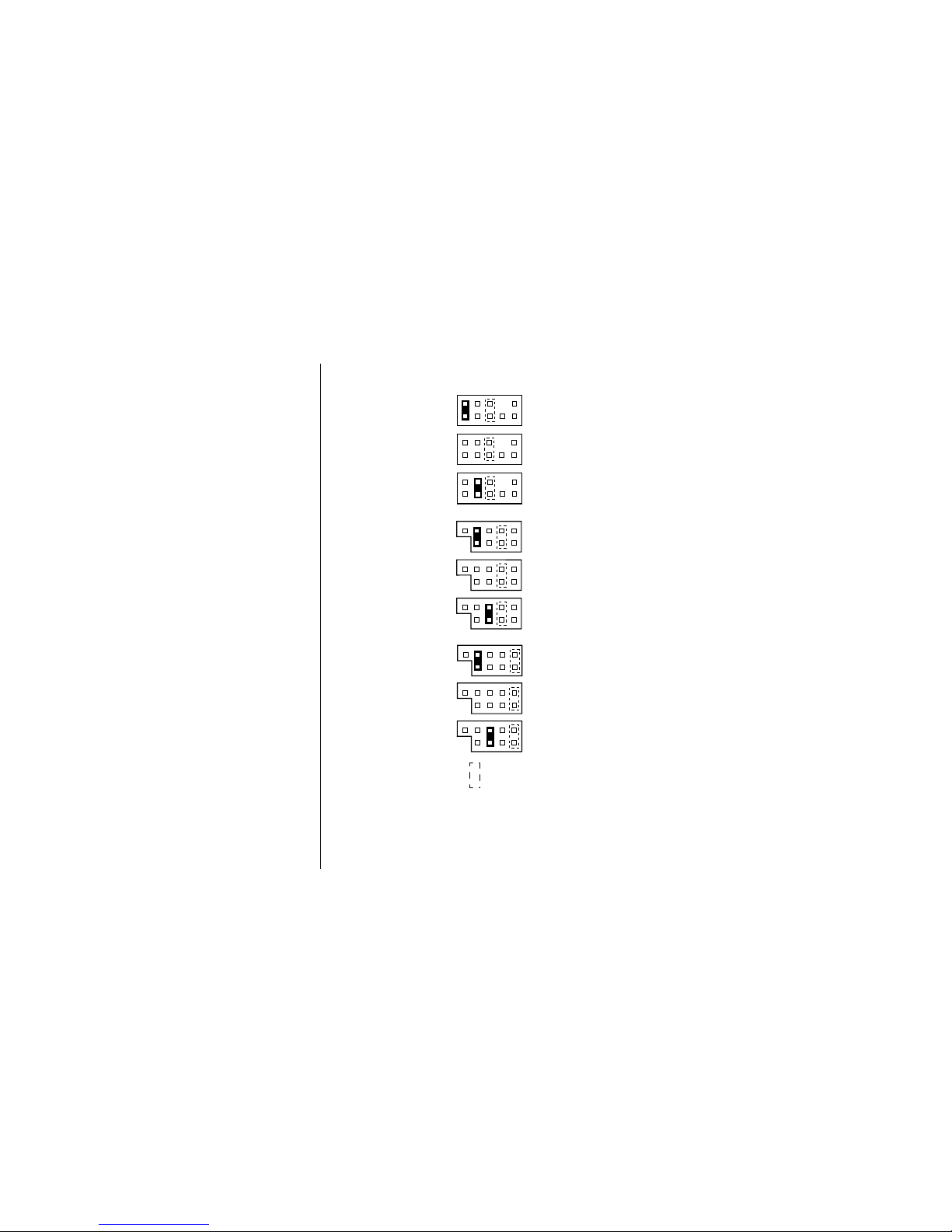
cylinder
(CLJ) makes the hard drive's capacity appear smaller to
presence of an ATI
absence of an
Master
Slave
Cable
Select
Master
Slave
Cable
Select
Master
Slave
Cable
Select
Figure 6. Jumper Positions
Jumper Style B
Jumper Style C
Jumper Style A
(CLJ) Capacity
Limitation
Jumper
Page 10
Installing the Hard Drive 7
2
Mounting the Hard Drive
Before mounting the hard drive in your system, you need to determine whether you are
installing the hard drive in a 3.5-inch or 5.25-inch device bay. If you are unable to locate an
available device bay in your computer, please consult your system user manual.
3.5-inch Device Bay Installation
When installing the hard drive in a 3.5-inch device bay, you do not need to use mounting
brackets. Many systems have an available 3.5-inch bay located adjacent to the floppy drive.
➤
Mount the hard drive in the 3.5-inch bay using four of the screws included in the
kit. See Figure 7.
Some systems may not have enough room to plug in the cables after the hard drive is
mounted. You may need to attach the ATA and power supply cables first.
"
Page 11
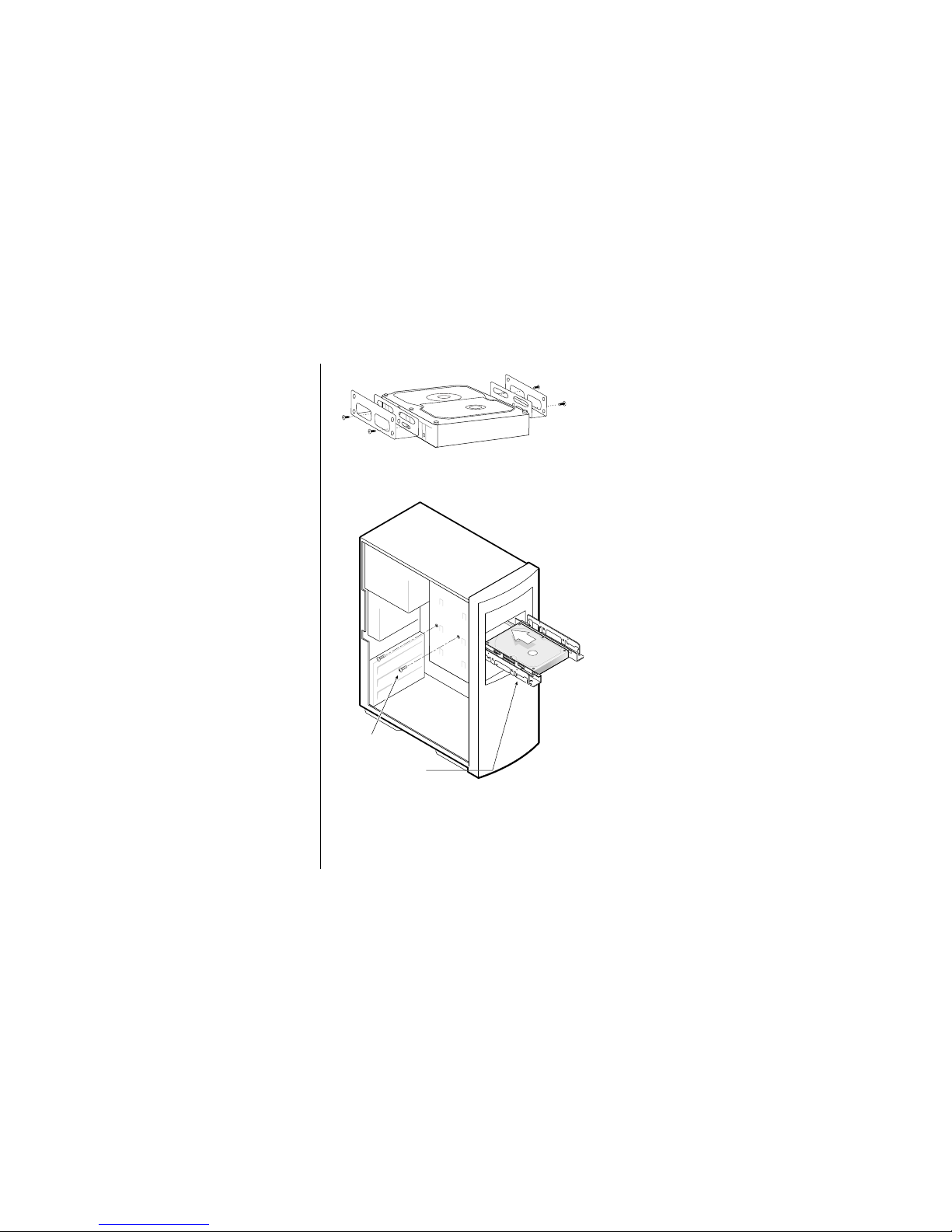
Mount the hard drive as close to
Figure 8. Mounting the Brackets on
the Hard Drive
Mounting Screws
Mounting Bracket
Mounting
Screws
Mounting
Bracket
Figure 9. Typical 5.25-inch Device Bay
Installation with Mounting Brackets
Page 12

Installing the Hard Drive 9
2
Attaching the Cables
An Ultra ATA cable (included) no longer than 18 inches is recommended for all UDMAcapable hard drives and is required for hard drives configured as cable select. Maxtor strongly
recommends using the Ultra ATA cable included in this package.
The provided Ultra ATA cable has a striped edge indicating pin #1 and a key notch on each
connector. The power cable connector is also keyed to prevent improper connection to the
hard drive.
When connecting the power or ATA cable, push the connector straight into its socket. Do
not rock the connector into place, as this can damage the hard drive or the system.
1.
Locate an available ATA connector on the motherboard or an installed ATA PCI
adapter card. If you are unable to locate this connector, consult the user manual for your
system or ATA adapter card.
2.
Plug the blue connector on the provided Ultra ATA cable straight into the ATA
connector on your motherboard or ATA adapter card. The correct orientation of the
cable connector can be found by matching the key notch on one side of the cable connector
with the corresponding groove in the ATA connector.
3.
If the hard drive has been configured as a master, plug the black cable connector
into the ATA connector on the rear of the hard drive. If the hard drive has been
configured as a slave, plug the gray cable connector into the ATA connector on
the hard drive.
4.
Connect the power cable to the hard drive.
5.
If you are attaching a second device to the same ATA cable, plug the ATA and
power connectors into this device.
DC Power
Connector
Bevel
Page 13

Primary Master, 0
Primary
Figure 11. Typical Device Configuration
(Boot Drive)
Primary Slave, 1
(Additional
Storage)
Connection
Motherboard
Secondary
Connection
Motherboard
Secondary Master, 0
(CD-ROM)
Secondary Slave, 1
(Open)
Page 14

Installing the Hard Drive 11
2
Existing System 2
(See “Installing Hard Drive as an Additional Hard Drive” on page 21.)
Cable Position Device
Primary Master, 0: Boot Drive
Primary Slave, 1: Additional Storage Drive
Secondary Master, 0: CD-ROM
Secondary Slave, 1: CD-ROM or DVD
Existing System 3
(See “Installing Hard Drive as an Additional Hard Drive” on page 21.)
Cable Position Device
Primary Master, 0: Boot Drive
Primary Slave, 1: Additional Storage Drive
Secondary Master, 0: Additional Storage Drive
Secondary Slave, 1: CD-ROM or DVD
Page 15

configuring the system BIOS . Your computer system
Figure 12. Typical BIOS Setup Message
Page 16

Installing the Hard Drive 13
2
a.
Press the pause/break key after the memory count to pause the system boot.
The pause/break key is usually located in the upper right corner of your keyboard (see
Figure 13). Pausing the boot will give you time to locate the function key message.
b.
Press the Enter key to resume system boot.
3.
Immediately after the function key appears, press the indicated key to enter
Setup.
Within the BIOS Setup utility, navigation is limited to keyboard commands. The active
function keys are usually Esc, Tab, PG/UP, PG/DN, Enter, +, -, spacebar, number, and
arrow keys. The BIOS Setup utility usually has function key instructions located somewhere
on the screen.
4.
Upon entering Setup, highlight the auto-detect IDE/HDD hard drives option (if
displayed) and press Enter. This will allow the system to automatically detect the devices
on your primary and secondary ATA channels.
Some BIOS Setup utilities do not have an auto-detect option on the first page. In this case,
choose the Standard CMOS option to detect the hard drive.
5.
After the hard drives are detected, save the settings.
If you are unable to locate the function key message to enter CMOS Setup or are
experiencing difficulty with hard drive detection in the BIOS, refer to your system manual
or contact your system manufacturer.
6.
Exit Setup and power off the system.
"
Page 17

Page 18

Formatting the Hard Drive 15
3
Formatting the Hard Drive
This chapter describes how to format and partition your new hard drive using the MaxBlast
Plus II software on a Windows system.
Do not create partitions larger than 137 GB using MaxBlast Plus unless
your motherboard,
BIOS, operating system, and ATA host controller properly support 48-bit Logical Block
Addressing (LBA). Creating partitions larger than 137 GB on systems that do not support
48-bit LBA can result in data loss. The Maxtor Ultra ATA/133 PCI Adapter Card fully
supports 48-bit LBA and can be purchased (in the U.S.) from www.maxtordirect.com.
Some newer motherboards with Intel chipsets can be updated to support 48-bit LBA using
the Intel Application Accelerator software available from www.intel.com.
Some tools built into Windows 98/ME, such as Scandisk and Defrag, do not function
properly on hard drive partitions larger than 127 GB. Third-party utilities such as Norton
Utilities 2002 can be used to replace the functionality of Scandisk and Defrag for partitions
larger than 127 GB.
When installing the hard drive on a Macintosh system, format (initialize) and partition
your hard drive using the Apple Drive Setup utility (for classic Mac OS) or the Apple Disk
Utility (for Mac OS X). In order for your Macintosh to recognize the full capacity of an
internal hard drive larger than 137 GB you must use a third-party, Macintosh-compatible,
Ultra ATA/133 PCI adapter card.
Choose from one of the following typical hard drive installation options:
• New system with boot drive installation or replacing a failed boot drive in an existing
system. See “Installing Hard Drive as a Boot Drive” on page 16.
• Existing system with original boot drive and you want to copy all data to the new hard
drive. See “Installing Hard Drive to Replace an Existing Drive” on page 20.
Page 19

Page 20

Formatting the Hard Drive 17
3
6. Click Next to continue. Allow the MaxBlast Plus II program to partition and format the
hard drive using the Standard Partitions option. Your hard drive is automatically partitioned
to the largest capacity by default. The hard drive is assigned a single drive letter if installing
Windows 98 or newer operating system.
7. When MaxBlast Plus II is finished formatting the hard drive, remove the system
boot disk from the floppy drive and reboot the system.
8. Do one of the following:
If the system boots to the C:\ prompt:
a.
Insert your system boot disk into the floppy drive.
b. Press CTRL-ALT-DEL to restart the system.
c. Proceed to step 9.
If the system boots and the following message appears:
EZ-BIOS: Initializing
EZ-BIOS: Hold the CTRL key down for status screen or to boot from floppy
a. Press the CTRL key. This displays the status screen with the following message
at the bottom.
Press A to boot from the A:\ drive
b. Press A. The next screen will display the following:
Insert disk
Press a key
c. Insert your system boot disk and press any key on the keyboard.
d. Proceed to step 9.
9. When prompted to start the computer with CD-ROM support, select this option
so that Windows will load the CD-ROM driver.
Page 21

Page 22

Formatting the Hard Drive 19
3
4. Change to the i386 directory on the CD-ROM drive.
cd X:\i386 where X is the drive letter assigned to the CD-ROM drive.
5. Type WINNT /OX and press Enter. This command creates the three Windows NT 4.0
system boot disks.
To create Windows 2000 startup disks
1.
Boot the system with a Windows 98, SE, or ME startup disk.
2. Choose the Start Computer with CD-ROM Support option.
3. Insert the Windows 2000 system CD.
4. Change directories to the CD-ROM drive.
cd X: where X is the drive letter assigned to the CD-ROM drive.
5. Type MAKEBOOT and press Enter. This command creates the four Windows 2000
system boot disks.
To create Windows XP startup disks
Floppy-less Windows XP installations can only be performed from systems that are capable of
booting to the CD-ROM drive. For systems that are not capable of booting to the CD-ROM
drive, the contents of the Windows XP boot disks can be downloaded from the Microsoft Web
site (www.microsoft.com). These disks cannot be created from the Windows XP CD.
To install Windows XP from CD-ROM
When using MaxBlast Plus II to install Windows XP from CD-ROM:
1. Enter the system BIOS and check the boot sequence or boot order settings. They
may need to be changed to: Floppy > CDROM > IDE-0 or A,CDROM,C.
2. Save settings and exit setup.
3. Power the system down and restart with the MaxBlast Plus II disk in the floppy
drive and the MaxBlast Plus II CD in the CD-ROM drive.
Page 23

Page 24

Formatting the Hard Drive 21
3
7. After the system boots to the Windows desktop, double-click the My Computer
icon. You should see a new drive letter and icon.
8. Double-click the new drive letter. You should see all the files copied from your boot
drive to your new hard drive. If all of your files appear to have copied, you will now make
the new hard drive your boot drive.
9. Shut down Windows normally and power the system off. You can now switch your
new hard drive with the old original boot drive.
10. Unplug the cables and install your new hard drive on the primary ATA/IDE cable
in the master position. Install your old hard drive on the secondary ATA/IDE
cable.
Switching the hard drives may require changing the jumper settings before reattaching the
cables. For Maxtor hard drives, refer to the jumper illustrations on page 4. For other
manufacturers’ hard drives, check the product manual that came with the hard drive.
11. Power the system on.
12. At the Windows desktop, double-click the My Computer icon. You will see the
newly copied boot drive as drive letter C. The old hard drive can now be used for
additional storage.
Installing Hard Drive as an Additional Hard Drive
This section gives instructions for installing your new hard drive as additional storage on a
system with an existing boot drive.
1. With the system turned on, insert the MaxBlast Plus II disk in the floppy drive
and the MaxBlast Plus II CD in the CD-ROM drive.
"
Page 25

Page 26

Getting Help 23
4
Page 27

Page 28

Getting Help 25
4
Page 29

Page 30

Glossary 27
5
Page 31

Page 32

29
frequently asked questions 25
G
getting help 23
I
installing
additional hard drive 21
in 3.5" device bay 7
in 5.25" device bay 8
installing Windows XP 19
J
jumpers
cable select 5
cylinder limitation capacity 6
extra 6
setting 4
K
kit components 1
L
large capacity drives 1, 2, 25
O
operating system
requirements 1
P
partitioning
hard drive 15
Macintosh 15
positioning drives 10
Powermax diagnostic utility 26
precautions 1
PWRDIAG.EXE 26
R
replacing
existing hard drive 20
failed boot drive 16
required tools 2
S
setting jumpers 4
support 23
system BIOS 12
system requirements 1
T
tools required 2
troubleshooting 23
U
Ultra ATA cable 9
Ultra/ATA adapter card 2
Ultra/ATA PCI adapter card 2
W
Windows 2000 16, 18
Windows 98 1
Windows ME 1
Windows NT 1, 16, 18
Windows XP 16, 18
installing 19
Page 33

Page 34

Page 35

Copyright
© 2002 Maxtor Corporation. All rights reserved. Changes are periodically made to the information herein which will be incorporated in revised editions of this publication. Maxtor may make changes
or improvements to the product(s) described in this publication at any time and without notice. MaxBlast is a trademark and Maxtor is a registered trademark of Maxtor Corporation. All other brands
or products are trademarks or registered trademarks of their respective holders.
FCC Declaration of Conformance
This device complies with part 15 of the FCC Rules. Operation is subject to the following two conditions: (1) this device may not cause harmful interference, and (2) this device must accept any
interference received including interference that may cause undesired operation.
Maxtor Corporation
500 McCarthy Blvd., Milpitas, California 95035 USA
Part Number
20186800/A
 Loading...