

Page 1

Maxsine
EP
100 AC SERVO
QuickGuide
Maxsine Electric Co.,Ltd
Page 2
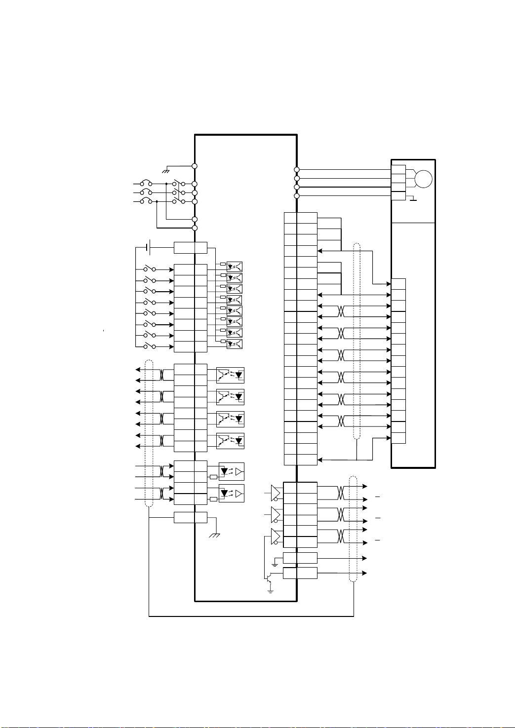
1.1 Standard wiring
Position control
3 Phase
AC220V
DC
12~24V
Servo ON(Enabled)
Alarm Clear
CCW Drive Inhibition
CW Drive Inhibition
Deviation Counter Clear
Command Pulse Inhibition
CCW Torque Limit
CW Torque Limit
Servo Ready
Servo Alarm
Positioning Completed
Mechanical Brake Release
Position Command
PULSE
Position Command
SIGN
NFB MC
COM+ 18
SON 10
ALRS 11
FSTP 12
RSTP 13
CLE 14
INH 15
FIL 16
RIL 17
SRDY+ 8
SRDY- 25
ALM+ 26
ALM- 27
COIN+ 28
COIN- 29
BRK+ 30
BRK- 31
PULS+ 32
PULS- 33
SIGN+ 34
SIGN- 35
FG 36
Maxsine
EP100(B) SERVO DRIVER
PE
R
S
T
r
t
CN1
4.7k
CN1
CN1
220
220
26LS31
Driver
Ground of
Metal Case
26LS32
Receiver
A
B
Z
CN2
CN1
U
V
W
PE
14 5V
15 5V
16 5V
17 5V
18 0V
19 0V
20 0V
21 0V
1 A+
2 A3 B+
4 B5 Z+
6 Z7 U+
8 U-
9 V+
10 V11 W+
12 W22 0V
23 0V
26 FG
1 OA+
2 OA-
3 OB+
4 OB-
5 OZ+
6 OZ-
9 GND
7
SERVOMOTOR
2
3
4
1
4 Pins Connector
For Motor Power
2
3
4
7
5
8
6
9
10
13
11
14
12
15
1
15 Pins Connector
For Optical Encoder
A
A
B
Output Signals
B
of Encoder
Z
Z
Ground of
GND
CZ
Encoder Signal
Z
Z Signal of Encoder
(OC Output)
Picture 1.1 Standard wiring for position control
2
Page 3
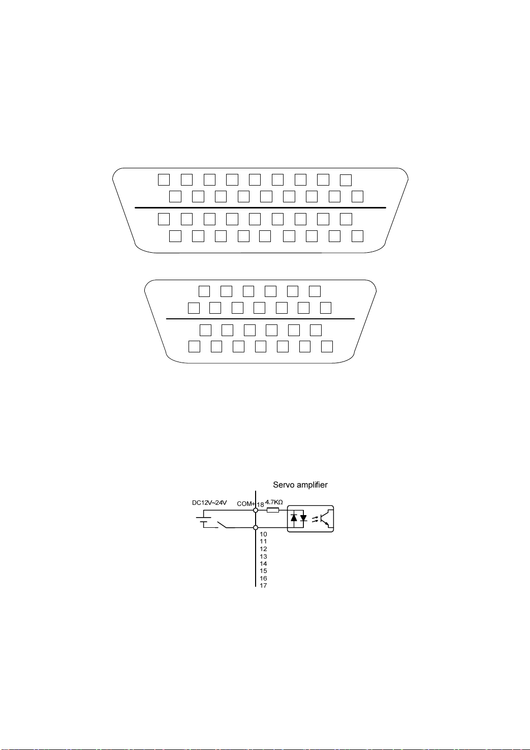
1.2 Terminal disposition for interface
Figure 3.1 is the disposition chart of terminal connector CN1 for the servo driver. CN1 is
the connector with 36 cores. Figure 3.2 is the disposition chart of terminal connector CN2 for
the servo driver. CN2 is the connector with 26 cores.
12
14
16
18 6
11
13
15
17
28
30
32
34
36
27
29
31
3335
Figure 2.1 the soldering lug of the CN1 plug(face to lug)
8
10
12
7
9
11
13
21
23
25
20
22
24
26
Figure 2.2 the soldering lug of the CN2 plug(face to lug)
1.3 Input/output interface type
1.3.1 Switch value input interfaces
810
79
25
4
5223201
2426
23
2
1921
6
5
19
18
24
13
1517
1416
z The range of external DC power supply is 12~24V, and the minimum input current is
100mA .
z Inverting the polarity of DC power source, which is provided by the user, can cause the servo
driver damage.
Page 4
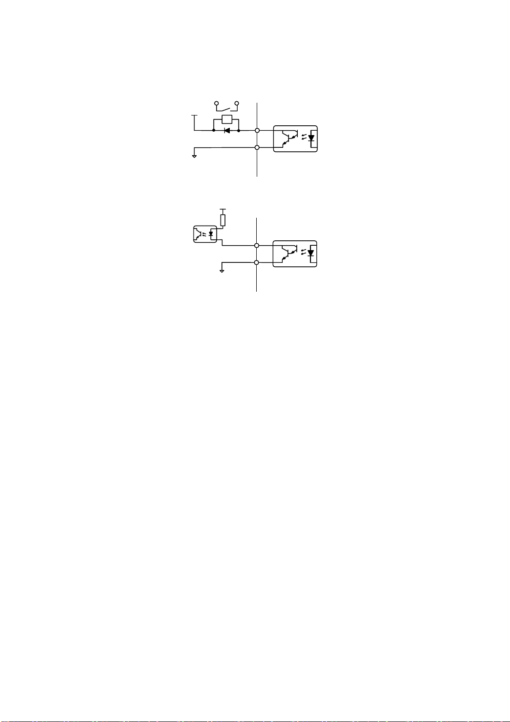
1.3.2 Switch value output interfaces
VCC
max 25V
Ground
Relay
Servo amplifier
8
26
28
30
25
27
28
29
Max Output 50mA
Relay connection
VCC
max 25V
Ground
Photo-coupler connection
The outputs use Darlington photo-coupler. It can be connected with relay, photo-coupler.
z
Servo amplifier
8
26
28
Max Output 50mA
30
25
27
28
29
z Inverting the polarity of DC power source, which is provided by the user, can cause the servo
driver damage.
z Open-collector circuit is used to transfer the outputs signal. the maximum current is 50mA,
the maximum voltage of external DC power supply is 25V. loads of the output signal should
be limited in that range, if not or directly connect to the power, can cause the servo driver
damage.
z When using relay like inductive loads, a free-wheel diode must be connected with the inductive
load in parallel. If the diode connects in wrong direction can cause damage to the output circuit.
z Owing to the low level of output is approximately 1V and cannot satisfy the TTL low-level
request, therefore cannot directly connect with the TTL circuit.
4
Page 5
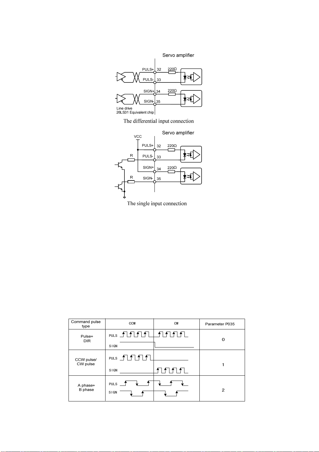
1.3.3 Pulse interfaces
z
The differential input connection is recommended for a correct transfer.
The RS422 driver(e.g AM26LS31、MC3487) is used to make the differential connection.
z
The action frequency will be fall down under a single connection. Base on the input circuit,
z
the driver current is in the range of 10~15mA , the maximum voltage of external DC power
supply is 25V, the R value will be got, Experience data:VCC=24V, R=1.3~2k; VCC=12V,
R=510~820Ω; VCC=5V, R=82~120Ω.
z Under the single connection, inverting the polarity of DC power source, which is provided by the
user, can cause the servo driver damage.
z The input mode、timing and parameters of the pulse are shown below, the arrow indicates the
counting edge. When use the mode of A、B phase, the maximum of the four times the frequency
is 500kHz.
Input pulse mode
5
Page 6

The maximum frequency is 500kHz
The maximum frequency is 500kHz
Parameter demand Pulse waveform of position command
Differential Single end
>2μs t >5μs
t
ck ck
t t
>1μs
h
h
tl>1μs
t <0.2μs t <0.3μs
t <0.2μs t <0.3μs
t >1μs
t >8μs t >10μs
tqh>4μs
tql>4μs
t <0.2μs t <0.3μs
t <0.2μs t <0.3μs
t >1μs
ql
>>2.5μs
tl>>2.5μs
t >2.5μs
tqh>5μs
t
>5μs
t >2.5μs
rh rh
rl rl
s s
qck qck
qrh qrh
qrl qrl
qs qs
The maximum frequency is 125kHz
Input pulse timing and parameters
6
Page 7
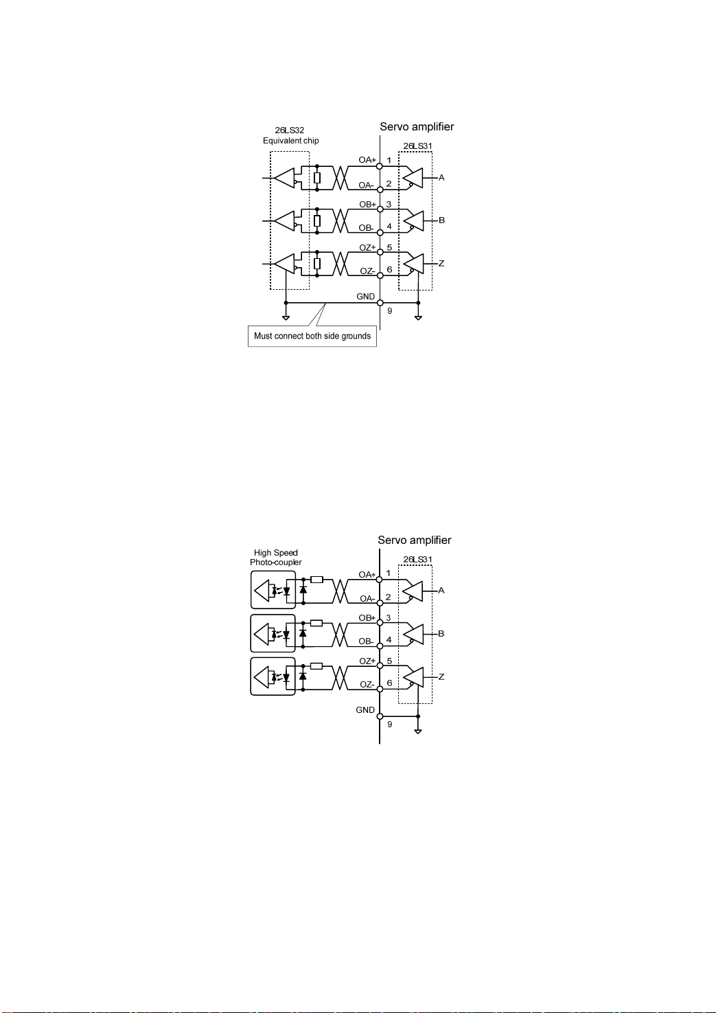
1.3.4 Encoder signals output interfaces
The encoder signals is transferred through the differential driver (e.g AM26LS31).
z
z On the host controller uses AM26LS32(or equivalent) to make the receiver, must connect the
terminal resistance, the value is about 330Ω;
z Encoder signal (GND) of servo driver must connect with the ground terminal on host
controller.
No isolation output.
z
The high-speed photo coupler (e.g. 6N137) can also be used on the host controller to make the
z
receiver.
7
Page 8
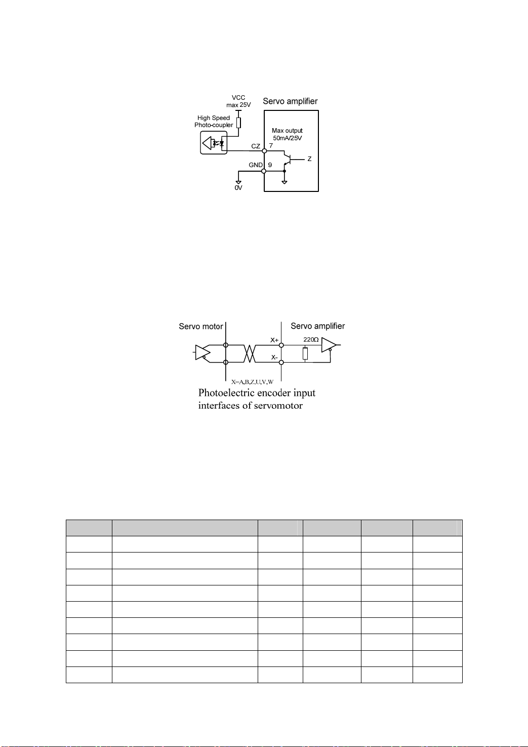
1.3.5 Open-collector output of encoder Z signal
The Z signal of encoder is transferred through the open-collector circuit, it output ON(Turn on)
z
when the Z signal appears or OFF(Turn off) when there is no Z signal appears.
No isolation output.
z
Because the width of the Z pulse is narrow, please use a high-speed photo-coupler to receive it
z
on the host controller.
1.3.6 Photoelectric encoder input interfaces of servomotor
1.4 Parameter table
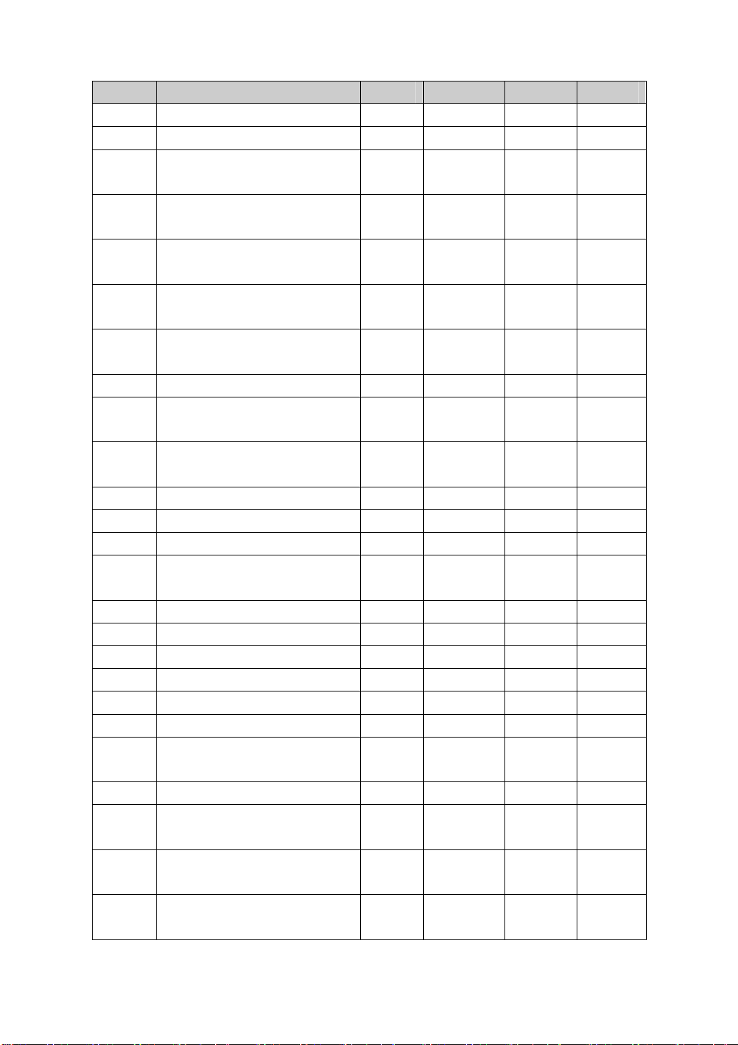
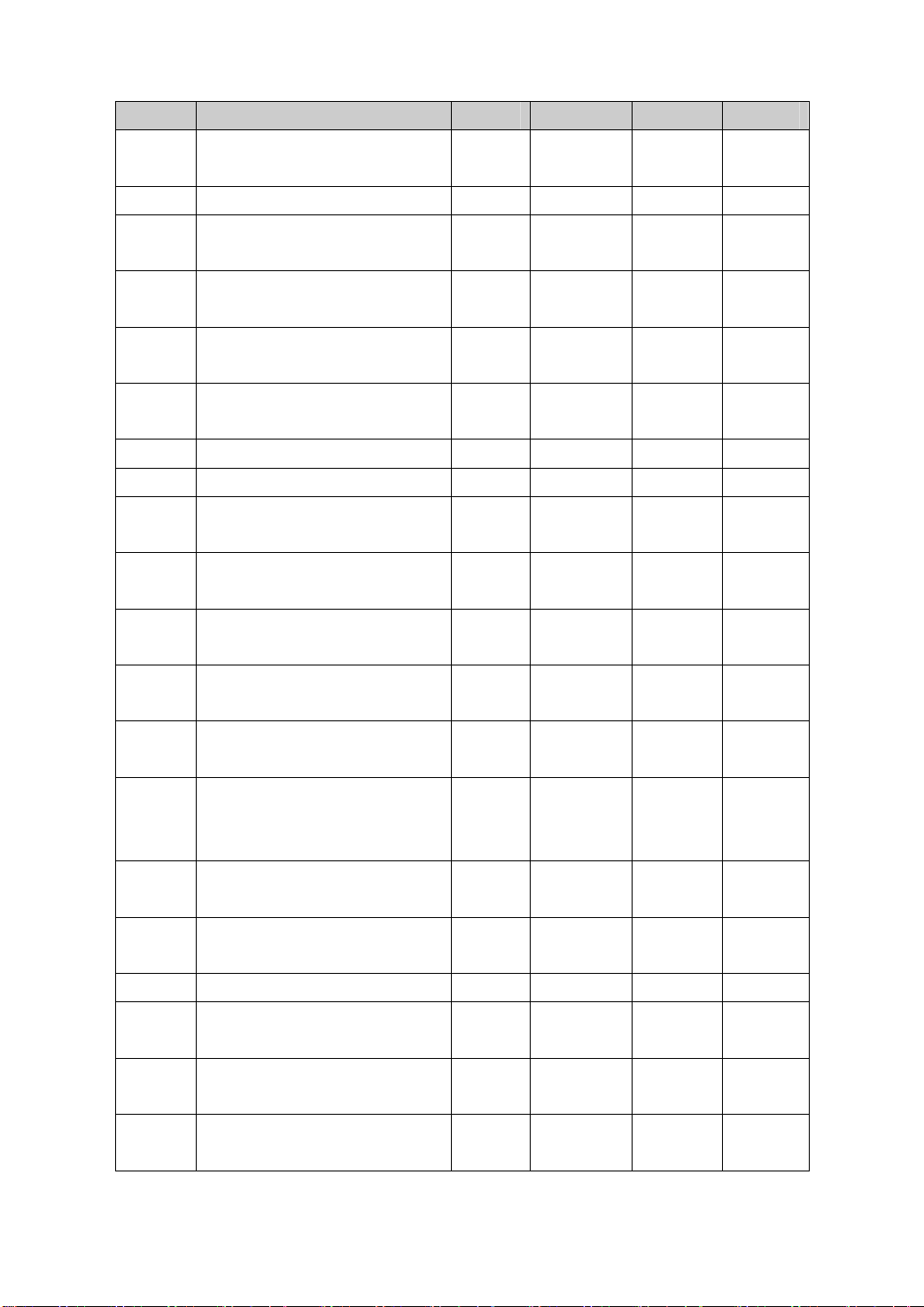
The default value in the next table take 110ST-M02030 (matches the EP100-2A drivers the
example. the parameter “*” symbol is possibly dissimilar in other models.
Table 4.1 User parameter table
Ordinal Name Usage Range Default Unit
0 Password
1 Identity code of servo driver
2 Software version (read only)
3 Status of initial display
4 Control mode selection
5 Proportional gain of speed loop
6 Integral time constant of speed loop
7 Filter of torque
8 Filter for speed detection
P,S,T
P,S,T
P,S,T
P,S,T
P,S,T
P,S
P,S
P,S,T
P,S
8
0~9999 315
0~51 30*
* *
0~21 0
0~6 0
5~2000 150* Hz
1~1000 20* ms
20~500 100 %
20~500 100 %
Page 9
Ordinal Name Usage Range Default Unit
9 Proportional gain of position loop P 1~1000 40 1/s
10 Feed forward gain of position loop P 0~100 0 %
11 Cut-off frequency of feed forward
filter for position loop
12 Numerator of frequency divider for
position command pulse
13 Denominator of frequency divider
for
position command pulse
14 Input mode of position command
pulse
15 Reversing direction of position
com
mand pulse
16 Positioning completed range P 0~30000 20 pulse
17 Position deviation limit for error
detection
18 Neglect excessive position deviation P 0~1 0
19 Smooth filter for position command P 0~30000 0 0.1ms
20 Neglect drive inhibition inputs
21 JOG running speed S -3000~3000 120 r/min
22 Internal/external speed command
selection
23 Maximum speed limit
24 Internal speed 1 S -3000~3000 0 r/min
25 Internal speed 2 S -3000~3000 100 r/min
26 Internal speed 3 S -3000~3000 300 r/min
27 Internal speed 4 S -3000~3000 -100 r/min
28 Arrival speed S 0~3000 500 r/min
29 Input gain of analog torque
command
30 Alarm level of torque overload
31 Detection time for torque overload
alarm
32 Permission of control mode
exchange
33 Inversing direction of analog torque
command
P 1~1200 300 Hz
P 1~32767 1
P 1~32767 1
P 0~2 0
P 0~1 0
P 0~30000 400
P,S,T
S 0~2 1
P,S,T
T 10~100 30 0.1V/100
P,S,T
P,S,T
P,S,T
T 0~1 0
0~1 0
0~4000 3600 r/min
1~300 300 %
0~32767 0 ms
0~1 0
×100
pulse
%
9
Page 10
Ordinal Name Usage Range Default Unit
34 Internal torque limit in CCW
direction
35 Internal torque limit in CW direction
36 External torque limit in CCW
dire
ction
37 External torque limit in CW
direction
38 Trial running in speed mode; Torque
limit in JOG operation
39 Zero offset compensation of analog
torque command
40 Acceleration time constant S 1~10000 0 ms
41 Deceleration time constant S 1~10000 0 ms
42 S-curve acceleration/deceleration
time constant
43 Gain of analog speed command S 10~3000 300 (r/min) /
44 Reversing direction of analog speed
command
45 Zero offset compensation of analog
speed command
46 Time constant of filter for analog
speed command
47 Action setting for electromagnetic
brake when servomotor is in
standstill
48 Action setting for electromagnetic
brake when servomotor is in motion
49 Action speed for electromagnetic
brake when servomotor is in motion
50 Speed limit in torque control T 0~5000 3600* r/min
51 Electronic gear is available in
dynamic
52 Second numerator of frequency
divider for position command pulse
53 Bottom four bits control word for
forcing the input terminal to be ON
P,S,T
P,S,T
P,S,T
P,S,T
S 0~300 100 %
T -2000~2000 0
S 1~1000 0 ms
S 0~1 0
S -5000~5000 0
S 0~1000 300 Hz
P,S,T
P,S,T
P,S,T
P 0~1 0
P 1~32767 1
P,S,T
0~300 300* %
-300~0 -300* %
0~300 100 %
-300~0 -100 %
V
0~200 0
0~200 50
0~3000 100 r/min
0000~1111 0000 Binary
×10ms
×10ms
10
Page 11
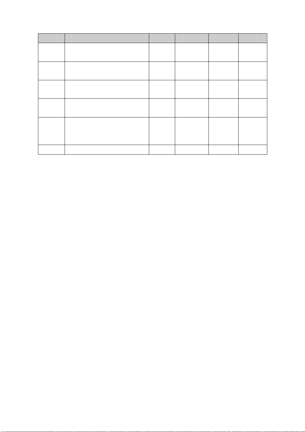
Ordinal Name Usage Range Default Unit
54 Top four bits control word for
forcing the input terminal to be ON
55 Bottom four bits control word for
inversing the terminal input signal
56 Top four bits control word for
inversing the terminal input signal
57 Control word for inversing the
terminal output signal
58 Time constant of input terminal for
removing the effect of vibrating
contact
59 Demonstration operation
P,S,T
P,S,T
P,S,T
P,S,T
P,S,T
P,S
0000~1111 0000 Binary
0000~1111 0000 Binary
0000~1111 0000 Binary
0000~1111 0000 Binary
1~1000 16 0.1ms
0~1 0
11
Page 12
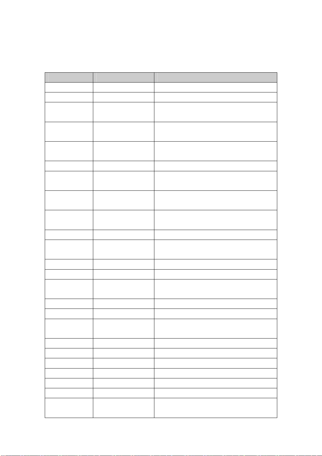
1.5 Alarm table
Alarm code Alarm name Alarm content
-- Normal
1 Over speed Servomotor speed exceeds the speed limit.
2 Over voltage of the
main power supply
3 Under voltage of the
main power supply
4 Position deviation
exceeds the limit value
5 Servomotor over heat The temperature of servomotor is too high
6 Saturation fault of the
7 Drive inhibition is
abnormal
8 Overflow of position
deviation counter
9 Encoder signal fault Lack of the signals of encoder
10 Under voltage of
control power supply
11 IPM model fault IPM intelligent model fault
12 Over current Over-current of servomotor
13 Overload Overload of servomotor and servo driver
14 Brake fault Fault occurs in brake circuit
15 Encoder counter error Encoder counter is abnormal.
16 Over-heat of
servomotor
17 Speed response fault Speed deviation is too big for a long time
19 Over heat reset System was reset by over heat fault
20 EEPROM error EEPROM is in error
21 U4 error U4 is in error
22 Reserved
23 U6 chip error U6 chip or current sensor is in error
29 Over torque alarm The torque of servomotor exceeds the setting value
speed amplifier
Table 5.1 Alarm table
The voltage of the main power supply exceeds the
specified value.
The voltage of the main power supply exceeds the
specified value.
The counter of position deviation exceeds the
setting limit value.
The speed regulator is in saturation status for a long
time
CCWL、CWL the inputs of drive inhibition are
OFF.
The absolute value of position deviation counter
exceeds 2
The voltage of control power supply is too low.
(instantaneous over heat)
The heat load of servomotor exceeds the setting
2
value (I
and sustained time
t detection)
30
Page 13

30 Lost Z signal of encoder Z signal of encoder is loss.
31 UVW signals error of
encoder
32 Illegal code of encoder
UVW signals
The UVW Signals error or pole number does not
match with the servomotor
UVW signals are all high level or low level
Page 14
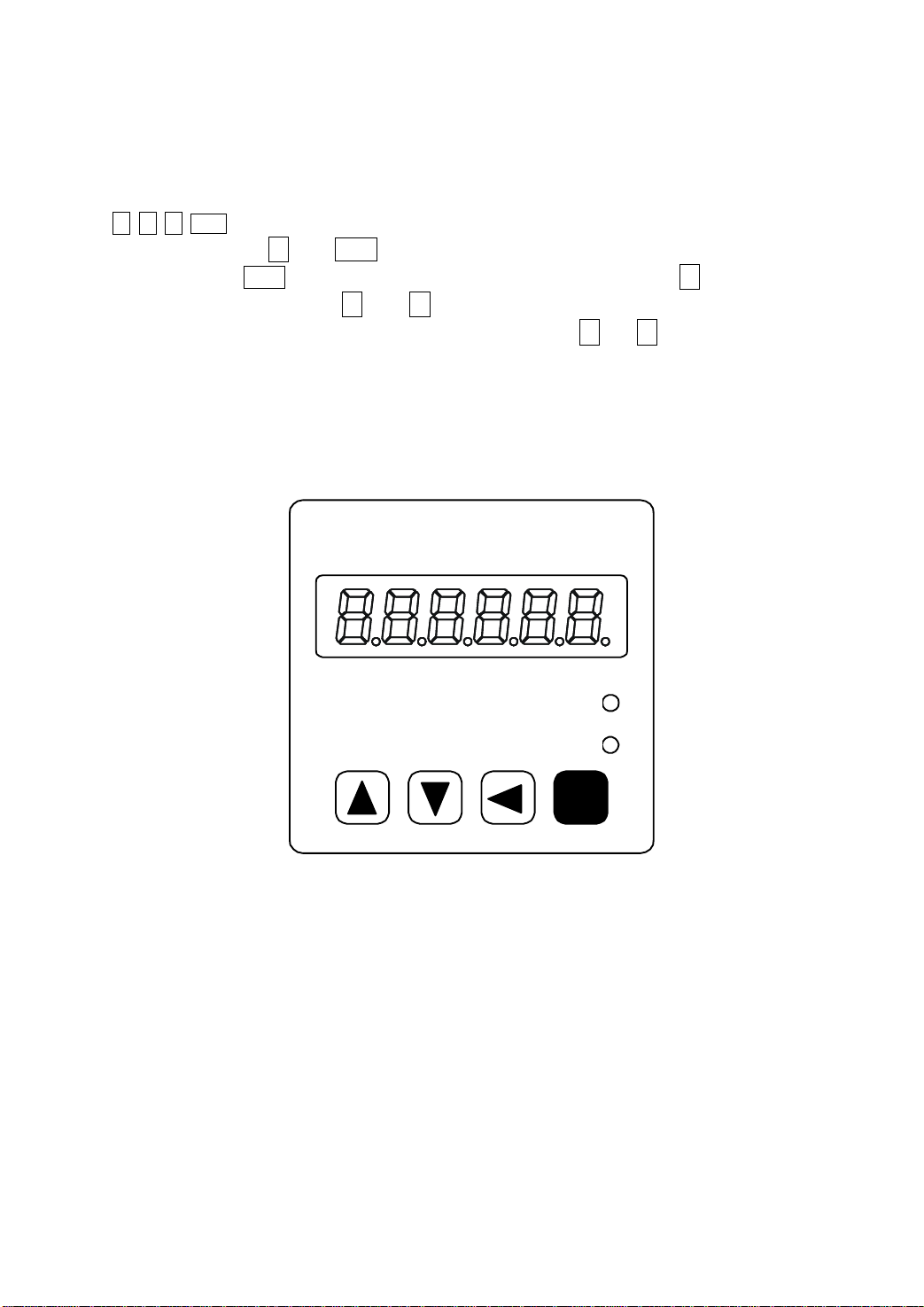
1.6 Display and button operation
The front panel consists of the display (6-digit, 7-segment LED) and four switching buttons
( ↑、↓、←、Enter ).
is executed in layer. ← and Enter button expresses the layer going backward and forward
respectively; The Enter button has the meaning of enter, confirm. The ← button has the
meaning of exit, cancel. The ↑ and ↓ button expresses increase and decrease of serial
number or value size respectively; if press down and hold the ↑ or ↓ button,then has the
effect of repeat for doing so; And the longer of holding the higher of repeat rate.
If 6 LED digit or decimal point of the most right side LED digit is twinkling, shows that
any alarm occurs. If the POWER lamp lit indicates that the main power supply is on. If the RUN
lamp has lit, indicates that the servomotor is in motion.
It is used for display the system status, parameter setting and so on. Operation
Maxsine
EP100 Series
AC Servo Amplifier
Picture 6.0 Front panel
Power
Run
Enter
Page 15
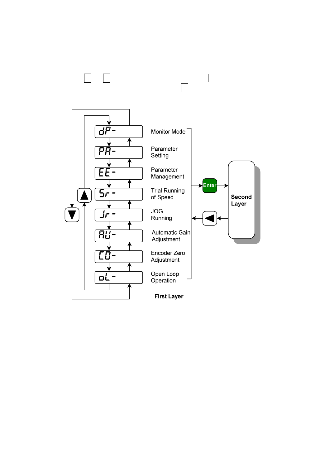
1.7 First layer
Use the first layer to select the operation mode, There are seven operation mode can be
selected by using ↑ or ↓ button,Then press down the Enter button for entering the second
layer that has selected. After that if press down the ← button, then return to the first layer
again.
Picture 7.0 Diagram of operation mode selection
Page 16
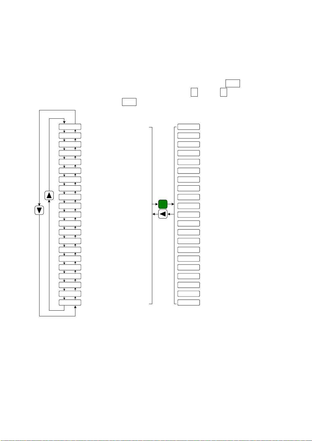
1.8 Second layer
1.8.1 Monitor mode
If has chosen the monitor mode “dP-@@@” in the first layer, Press the Enter button to enter
the monitor mode. There is twenty one monitor’s status. Use ↑ and or ↓ button to select the
needing monitor's status; Press the Enter button again to enter the concrete display condition.
dp-spd
dp-pos
dp-pos.
dp-[po
dp-[po.
dp-epo
dp-epo.
dp-trq
dp- i
dp-lsp
dp-[nt
dp-frq
dp- [s
dp- [t
dp-apo
dp- in
dp-out
dp-[od
dp- rn
dp-err
dp-res
Motor speed(r/min)
Bottom 5 digits of current position (pulse)
Top 5 digits of current position
(x100000 pulse)
Bottom 5 digits of current command (Pulse)
Top 5 digits of current command
(x100000Pulse)
Bottom 5 digits of current deviation (Pulse)
Top 5 digits of current deviation
(x100000Pulse)
Motor torque(%)
Motor current(A)
Linear velocity(m/min)
Current control mode
Pulse frequency of position command(kHz)
Speed command(r/min)
Torque command(%)
Absolute position of rotor in one turn(Pulse)
Status of input terminal
Status of output terminal
Input signals of encoder
Operation status
Alarm code
Factory reserve
Enter
r1000
p45806
p. 12
[45810
[. 12
e4
e. 0
t70
i2.3
l5.000
[nt 0
f12.6
r. -35
t. -20
a3265
In!!!!
out !!
[od!!!
rn- on
err 9
u0
Motor speed 1000r/min
Current position 1245806
pulses
Position command 1245810
pulses
Position deviation 4 pulses
Motor torque 70%
Motor current 2.3A
Linear velocity 5.000m/min
Control mode 0
Pulse frequency of position
command 12.6kHz
Speed command -35r/min
Torque command -20%
Absolute position of rotor 3265
Input terminal
Output terminal
Input signals of encoder
Operation status: in running
Number 9 alarm
Factory reserve
Picture 8.0 Diagram of monitor mode operation
Page 17
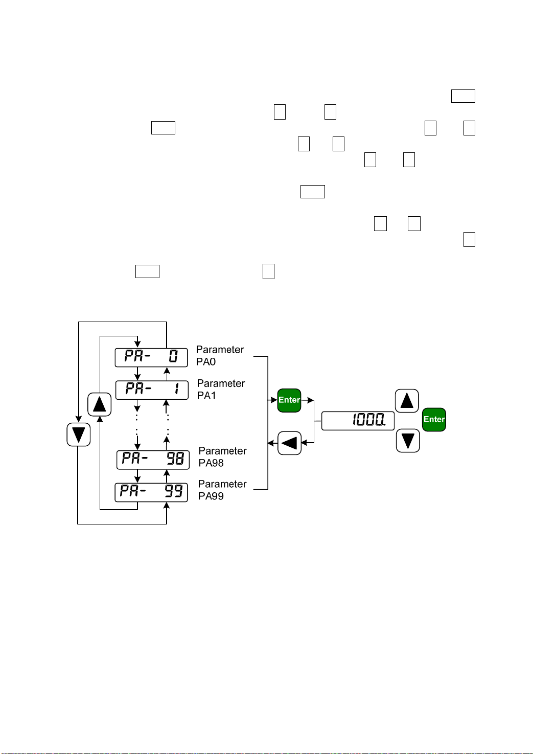
1.8.2 Parameter setting
If has chosen the parameter setting mode “PA-@@@” in the first layer, Press the Enter
button to enter the parameter setting mode. Use ↑ and or ↓ button to select the number of
parameter. Press the Enter button to display the value of selected parameter. Use ↑ and ↓
button to be able to modify the parameter value. Press ↑ (or ↓ ) button once to increase ( or
decrease) the parameter value by one. Pressing down and hold the ↑ ( or ↓ ) button, the
parameter can increase ( or decrease) continuously. When the parameter value is modified, the
decimal point on the most right sides LED is lit. Press Enter to confirm the parameter value to
be effective, meanwhile the decimal point is turned off. The modified parameter value is
immediately active to influence on the control. Hereafter pressing ↑ or ↓ button can
continue to modify the parameter. After finishing modification of parameter, press the ←
button to return to the parameter number selection. If the value of the parameter is not satisfied,
do not press the Enter button and can press ← button to cancel and to resume the original
parameter value and to return to the parameter number selection.
Picture 8.1 Diagram of parameter setting operation
Page 18
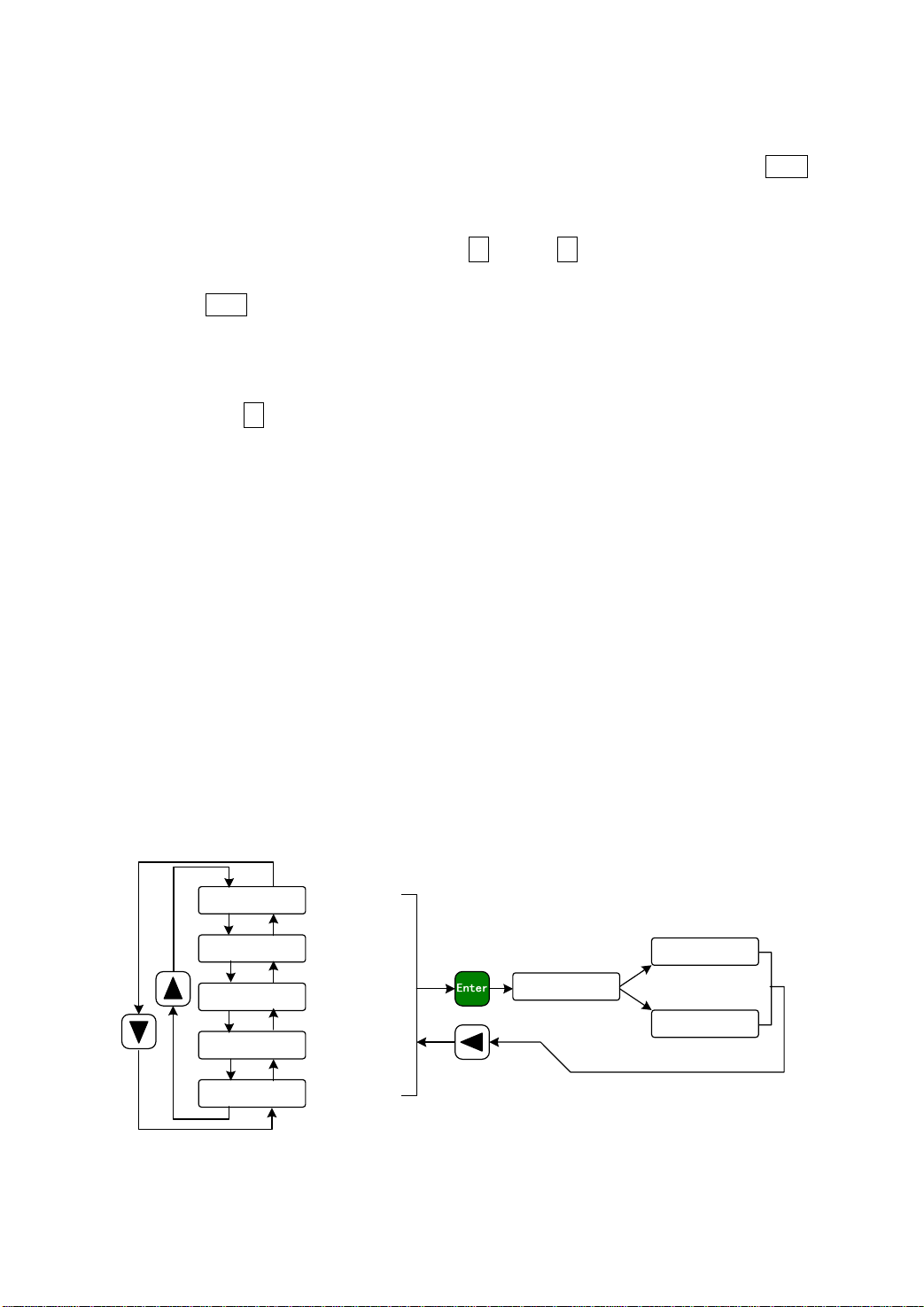
1.8.3 Parameter management
Choose the parameter management mode “EE-@@@” in the first layer. Press the Enter
button for entering the parameter management mode in which operation is performed between
the parameter list and the EEPROM.
There are five operation modes. First use ↑ and or ↓ button to select an operation
mode. Take “parameter write in” as the example, select “EE-Set” and then pressing down
and hold the Enter button at least three seconds to active the writing operation mode. The
“StArt@” is displayed in the front panel indicating that the parameter is writing into
EEPROM. Waiting for about 1 to two second, if the writing operation is successful, then the
“
FInISH” will display, if it is fail the “Error@” will display. After finished the operation
and then press the ← button for returning to the operation mode selection.
EE-SEt Parameter write
This operation indicates that the parameter in parameter list will write to EEPROM.
The user has made change to a parameter. This only change the value of the parameter in
parameter list, but in the next time when the power supply is on the parameter will restore its
original value. Making permanent change to a parameter value, it is the need to carry out the
parameter write operation and write the parameter to EEPROM, in later when the power
supply is on and will be able to use the parameter.
EE-dEF Resume default value
This operation indicates that each default value of all the parameters will read and
write to the parameter list and EEPROM. For the next time when power supply is on the
default parameters will be used by now. When many parameters become confusion and
cause abnormal operation, it is necessary to carry out this operation for resuming the
default parameters. There are different default parameters for different servo driver model
and the servomotor model. Therefore, before doing this operation the servo driver code
(Parameter P001) and the servomotor code (Parameter P002) must be selected correctly.
ee-set
ee- rd
ee- ba
ee- rs
ee-def
Parameters
wirte in
Parameters
read out
Parameters
backup
Resume
backup
Resume
default value
Press down and
hold for 3 second
Operation success
finisk
start
error
Operation fail
Picture 8.2 Diagram of parameter management operation
Page 19
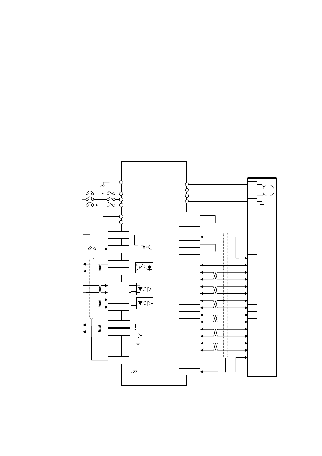
1.9 Operation of position control mode with simple wiring
Wiring
According to the picture 7.8 make the wiring carefully.
z The main circuit terminal R、S and T connect with three phase AC 220V power supply.
z The terminal ‘r’ and‘t’ of control power supply connect with single phase AC 220V power
supply.
z The output terminals(U,V,W) must be connected with the servo motor connections(U,V,W)
correspondently, otherwise the servo motor will stop or over speed.
z Using the encoder connector CN2 connect the servo driver with the servomotor.
z Using the control signal connector CN1 connect other wiring according to the drawing.
3 Phase
AC220V
12~24V
Servo ON(Enabled)
Servo Ready
Position Command
PULSE
Position Command
SIGN
Ground of
Encoder Signal
Z Signal of Encoder
(OC Output)
Maxsine
EP100(B) SERVO DRIVER
DC
GND
PE
R
S
T
NFB
MC
r
t
CN1
COM+ 18
4.7k
SON 10
SRDY+ 8
SRDY- 25
PULS+ 32
PULS- 33
SIGN+ 34
SIGN- 35
Z
FG 36
220
220
9GND
CZ
7
Ground of
Metal Case
CN2
26LS32
Receiver
U
V
W
PE
14 5V
15 5V
16 5V
17 5V
18 0V
19 0V
20 0V
21 0V
1 A+
2 A3 B+
4 B5 Z+
6 Z7 U+
8 U-
9 V+
10 V11 W+
12 W22 0V
23 0V
26 FG
Picture 9.0 Simple wiring diagram of position control mode
SERVOMOTOR
Motor
2
3
4
1
4 Pins Connector
For Motor Power
Optical Encoder
2
3
4
7
5
8
6
9
10
13
11
14
12
15
1
15 Pins Connector
For Optical Encoder
Page 20

Operation
z Turn on the control power supply and then the main power supply. The display of the
front panel is lit. The POWER indicating LED is lit.
z Set parameters according to the table below:
Number of
parameter
PA4 Control mode
PA12 Numerator of
PA13 Denominator of
PA19 Smooth filter for
PA20 Neglect drive
z Confirming that there is neither any alarm nor any unusual situation, the servo enable
(SON) signal is given, then the RUN indicating LED lit and the servomotor is active at
zero speed state by now
the servo driver and make the servomotor running under low speed.
explanation Setting value Default value
0 0
selection
electronic gear
electronic gear
By user
setting
By user
setting
1
1
0 0
position command
1 0
inhibition inputs
. Send low frequency command pulse from the host controller to
 Loading...