

Page 1
USER MANUAL
Edition 2018-03
Document ID rel7971
Page 2

Contents
Contents
1Operation 3
1.1 Components . . . . . . . . . . . . . . . . . . . . . . . . . . . . . . . . . . . . . . . . . . . . . . . . . . . .3
1.2 Legal Regulations . . . . . . . . . . . . . . . . . . . . . . . . . . . . . . . . . . . . . . . . . . . . . . . .4
1.3 Functional Principle . . . . . . . . . . . . . . . . . . . . . . . . . . . . . . . . . . . . . . . . . . . . . .4
1.4 Driving Modes . . . . . . . . . . . . . . . . . . . . . . . . . . . . . . . . . . . . . . . . . . . . . . . . . . .4
1.5 Handling. . . . . . . . . . . . . . . . . . . . . . . . . . . . . . . . . . . . . . . . . . . . . . . . . . . . . . . .5
1.5.1 PowerGrip . . . . . . . . . . . . . . . . . . . . . . . . . . . . . . . . . . . . . . . . . . . . . . .5
1.5.2 Battery . . . . . . . . . . . . . . . . . . . . . . . . . . . . . . . . . . . . . . . . . . . . . . . . . .6
1.5.3 Displays . . . . . . . . . . . . . . . . . . . . . . . . . . . . . . . . . . . . . . . . . . . . . . . . .7
1.6 Before the Ride . . . . . . . . . . . . . . . . . . . . . . . . . . . . . . . . . . . . . . . . . . . . . . . . . .8
1.7 Riding the Bike . . . . . . . . . . . . . . . . . . . . . . . . . . . . . . . . . . . . . . . . . . . . . . . . . .9
1.7.1 Power Limitation . . . . . . . . . . . . . . . . . . . . . . . . . . . . . . . . . . . . . . . . . .9
1.7.2 Motor Power . . . . . . . . . . . . . . . . . . . . . . . . . . . . . . . . . . . . . . . . . . . . .9
1.7.3 Battery Capacity . . . . . . . . . . . . . . . . . . . . . . . . . . . . . . . . . . . . . . . . 10
1.8 After the Ride . . . . . . . . . . . . . . . . . . . . . . . . . . . . . . . . . . . . . . . . . . . . . . . . . 11
2Maintenance 13
2.1 Care & Maintenance. . . . . . . . . . . . . . . . . . . . . . . . . . . . . . . . . . . . . . . . . . . . 13
2.1.1 After each Ride . . . . . . . . . . . . . . . . . . . . . . . . . . . . . . . . . . . . . . . . . 13
2.1.2 Storage of the Battery . . . . . . . . . . . . . . . . . . . . . . . . . . . . . . . . . . . 15
2.1.3 Periodic Inspection . . . . . . . . . . . . . . . . . . . . . . . . . . . . . . . . . . . . . . 15
2.1.4 Replacing the rear Brake Disc . . . . . . . . . . . . . . . . . . . . . . . . . . . . . 16
2.1.5 Cleaning the PowerGrip . . . . . . . . . . . . . . . . . . . . . . . . . . . . . . . . . . 22
2.1.6 Spare Parts. . . . . . . . . . . . . . . . . . . . . . . . . . . . . . . . . . . . . . . . . . . . . 25
2.2 Troubleshooting . . . . . . . . . . . . . . . . . . . . . . . . . . . . . . . . . . . . . . . . . . . . . . . 33
2.3 Disposal . . . . . . . . . . . . . . . . . . . . . . . . . . . . . . . . . . . . . . . . . . . . . . . . . . . . . . 34
3Technical Data 35
WARNING!
RIDING AN ELECTRIC BIKE IS DANGEROUS!
ALWAYS USE EXTREME CAUTION WHEN USING THIS PRODUCT. MISUSE
OF THIS PRODUCT COULD RESULT IN SERIOUS INJURY OR DEATH. ONLY
USE THIS PRODUCT IF YOU ARE IN GOOD PHYSICAL HEALTH. NEVER ACT
IN A CARELESS MANNER WHEN USING THIS PRODUCT. YOU ARE
RESPONSIBLE FOR YOUR SAFETY AND THE SAFETY OF OTHERS AROUND
YOU WHEN USING THIS PRODUCT!
2 maxon BIKEDRIVE | User Manual | rel7971
Page 3
SYMBOLS USED
Indicates a potentially hazardous situation. Ignoring can cause serious
injury!
Indicates a possibly dangerous situation or draws attention to an unsafe
practice. Ignoring can cause injury or damage to components!
Indicates an important aspect. Ignoring can cause damage to components!
In illustrations, only the “eye” will be displayed.
Indicates an important aspect or gives important additional information.
Operation
Components
1OPERATION
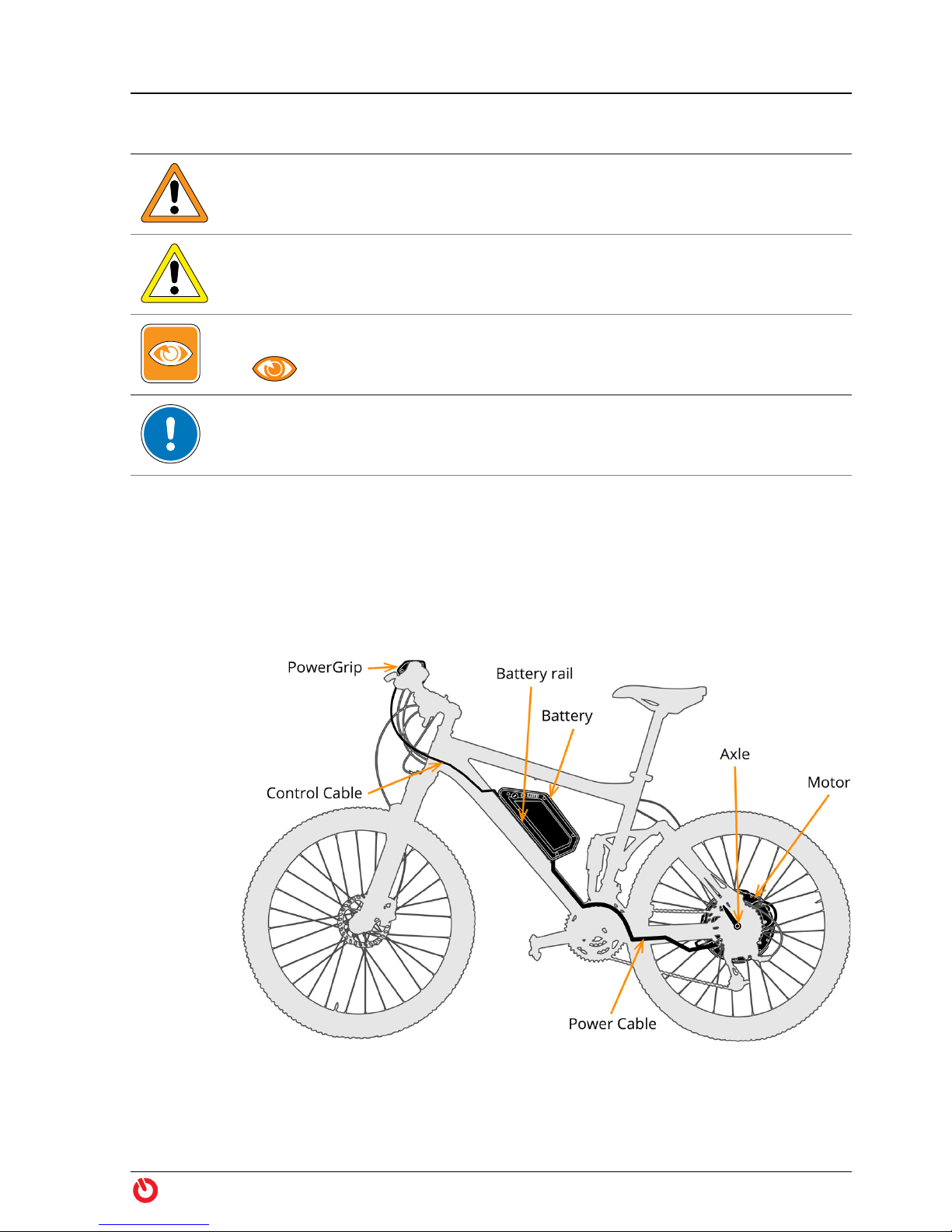
1.1 Components
Figure 1 maxon BIKEDRIVE — Components
maxon BIKEDRIVE | User Manual | rel7971 3
Page 4

Operation
Legal Regulations
1.2 Legal Regulations
Legal regulations
Inquire about the current legal requirements in your country or in your area before
putting your bike into operation.
Equipped with the BIKEDRIVE, the bike is a vehicle with motorized assistance.
Depending on the country, the vehicle is called E-Bike, Pedelec (Pedal Electric
Cycle), electric or motor-assisted bicycle, electro moped, autocycle, or similar,
and is subject to appropriate legal regulations.
Federal, State, and in some cases, city laws regulate aspects, such as, traffic
rules, permitted speed, type approval and homologation, license plate, prove of
roadworthiness/road suitability before an official body, compulsory insurance,
driving license, required equipment (for example, lighting, acoustic warning
device, and specific brakes), etc.
1.3 Functional Principle
From a
standing
start in
action!
1.4 Driving Modes
Zero Motorized assistance is deactivated. You may switch to «Zero» at any time and
Power1
Power2
Power3
Boost While pedaling in the highest support level «Power3», you can continue turning
Pushing aid If you activate «Boost» without pedaling, the motor will support you while push-
Motorized assistance of the BIKEDRIVE commences as soon as you start pedaling while having selected a support level. The motor develops torque according
to the selected support level and the driven speed.
You can switch off and re-activate the motorized assistance at any time. Without pedaling, you can use the motor as pushing aid.
continue “normal cycling”. Thereby, the BIKEDRIVE behaves as if completely
switched off. It runs in internal freewheel and you will not even notice that it is
there.
You will be motor-assisted while pedaling. The torque applied by the drive will
be determined by the support level you have selected with the PowerGrip and
the driven speed.
the PowerGrip to get extra short-term performance and torque.
ing the bike.
4 maxon BIKEDRIVE | User Manual | rel7971
Page 5
1.5 Handling
Operation
Handling
A Word on
Safety
Selecting the
driving mode
The BIKEDRIVE is extremely powerful! It possesses an extraordinarily high
degree of dynamics that will most likely surprise you at the beginning and it will
require some time to get used to.
Take it easy to start with and use caution on your first rides!
WARNING
Risk of injury
The BIKEDRIVE it extremely powerful and highly dynamic. Lack of habituation
to the high performance, handling, or operation can lead to serious injury!
• Be aware that the BIKEDRIVE will fundamentally change the driving behavior
of your bike — particularly in respect to aspects, such as, weight, weight distribution, center of gravity, braking distance, braking response!
• Use extra caution during the “acclimatization phase” and select a low degree
of motorized assistance!
• Be aware that a changed setting at the PowerGrip will have an immediate
effect on the drive system, on speed, and on handling!
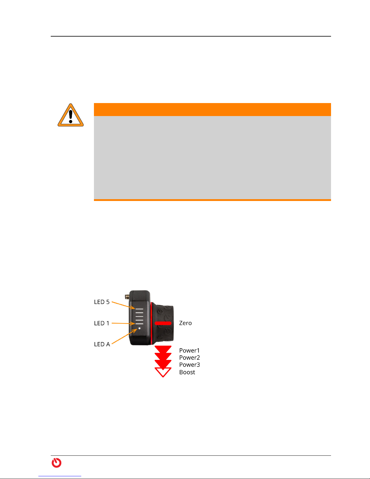
1.5.1 PowerGrip
By rotating the PowerGrip you select the driving mode and, thereby, the degree
of motorized assistance (“Driving Mode” on page 7). You select the level using
four snap-in and one non-latching positions.
Each change of the selected support level is temporarily displayed by LEDs 1…5.
Following a support level change and while riding, the LEDs will show the
remaining battery level (“Charging Level” on page 8). The system status is
continuously displayed with LED A (“Status Indicator” on page 8).
Figure 2 PowerGrip
maxon BIKEDRIVE | User Manual | rel7971 5
Page 6
Operation
Handling
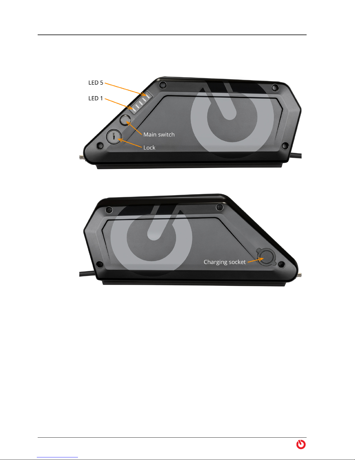
1.5.2 Battery
On the battery you will find the main switch, a lock, and displays for battery
charge and battery system status (page 8).
Figure 3 Battery BX360 ONE / BX500 ONE (left side)
Figure 4 Battery BX360 ONE / BX500 ONE (right side)
Power up To power up the battery, press the main switch. During startup, all LEDs light
up. After successful initialization, the LEDs will go out for a moment. Subsequently, the charging level of the battery will be temporarily displayed before
the LED display will go off.
To display the battery charge level at anytime during your ride, press the main
switch.
Turn off To turn off the battery, press the main switch until the LED display goes off. This
takes about 3 seconds. This takes about 3 seconds.
6 maxon BIKEDRIVE | User Manual | rel7971
Page 7
Operation
Handling
1.5.3 Displays
The PowerGrip features an LED display that will inform you about the currently
selected driving mode, the charging level of the battery, and the status of the
system. A second LED display for the charging level is located at the battery.
Dimming To prevent glare, the brightness of the PowerGrip’s LED display will automati-
cally adapt to the ambient light.
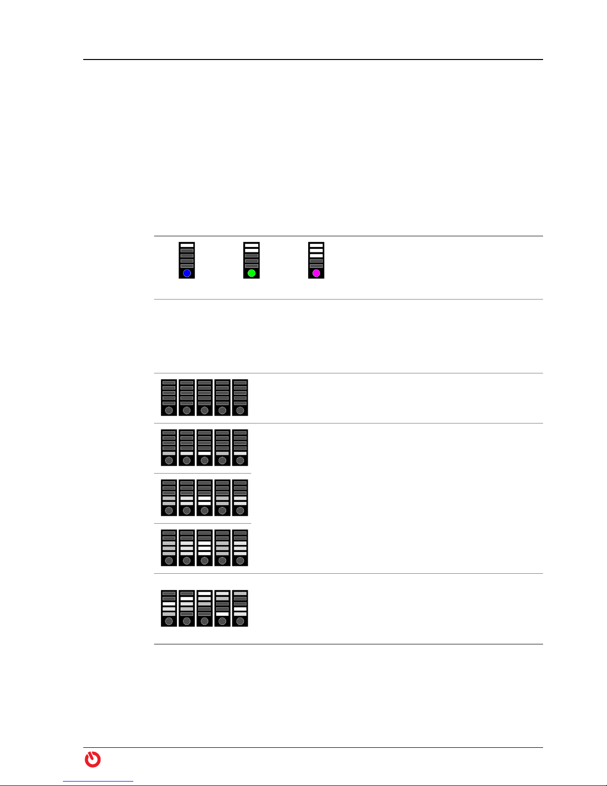
Identification of the PowerGrip
During initialization of the system, the type of PowerGrip is displayed via the
LEDs.
Identification
dotX25 dotX33 dotXUrban
Zero
Power1
Power2
Power3
Boost
Driving Mode
The selected support level is briefly displayed with each change. Thereafter, the
battery charge level is indicated.
Neutral position — motorized assistance is turned off.
The PowerGrip engages in this position.
Turning towards you from the neutral position «Zero»
switches consecutively into levels «Power1», «Power2»,
and «Power3».
Turning away from you switches consecutively one level
back.
The PowerGrip engages in the selected position.
Turning towards you from the level «Power3» switches
to level «Boost».
The PowerGrip does not engage in this position and
bounces back to level «Power3» when released.
maxon BIKEDRIVE | User Manual | rel7971 7
Page 8
Operation
Before the Ride
Charging
level
Operating
condition
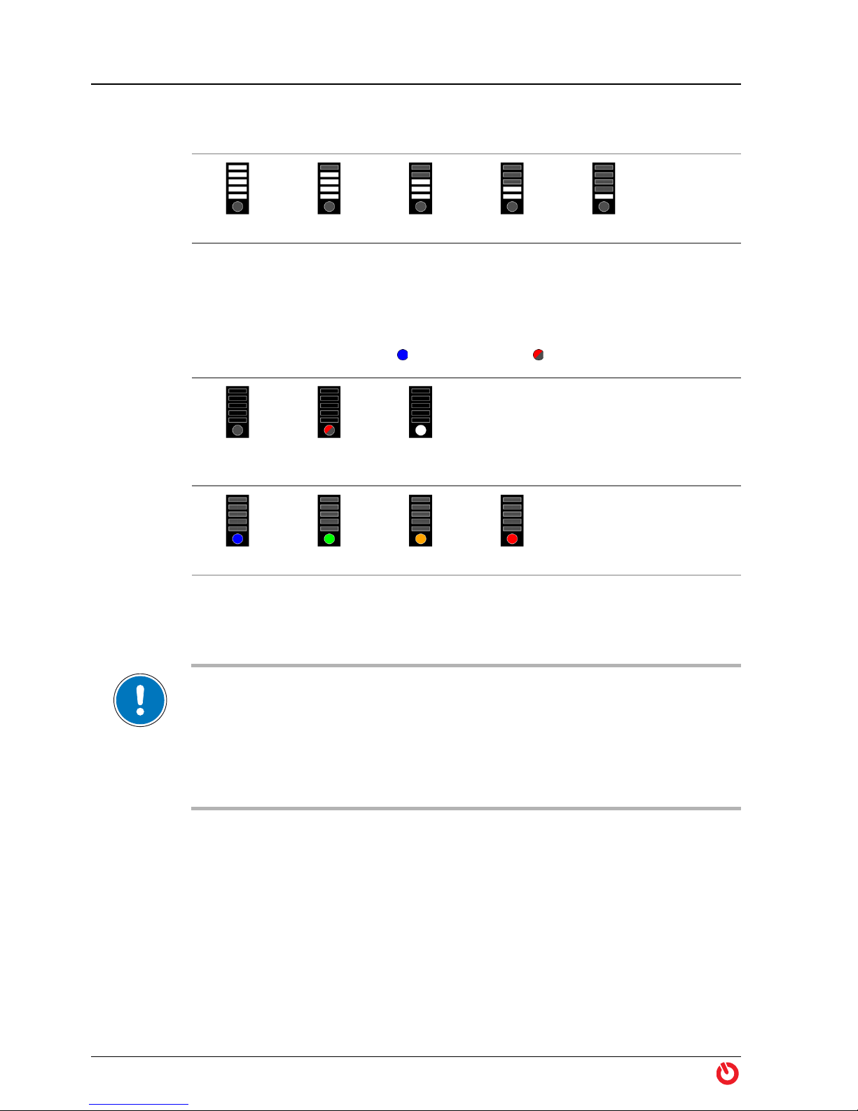
Charging Level
The remaining relative capacity of the battery is displayed in 20% steps.
100…80% 80…60% 60…40% 40…20% 20…0%
Status Indicator
The operating condition and system temperature (in color graduation) is displayed.
The meaning, for example, is lights up in blue, flashes in red.
System
off
System
error
Master
halted
System
temperature
cold normal heated warm
1.6 Before the Ride
IMPORTANT—Power-up procedure
During power-up procedure, the BIKEDRIVE will perform a self test and initialization.
Moving the bike contrary to the driving direction during this process can lead to malfunction. Therefore, while power-up procedure is in process,…
• do not rotate the rear wheel backwards (contrary to the driving direction),
• do not block the rear wheel,
• do not apply brakes!
1) Make sure that the battery is sufficiently charged for your planned
tour.
2) Make sure that the battery is turned off (page 6).
3) Slide battery into battery rail, let it click into place, and lock it. Remove
key.
“Riding the Bike” on
page 9
4) Turn PowerGrip in neutral position «Zero».
5) Turn on main switch on battery.
6) After successful initialization you are good to go. Bear in mind the
safety notes on page 5!
8 maxon BIKEDRIVE | User Manual | rel7971
Page 9
1.7 Riding the Bike
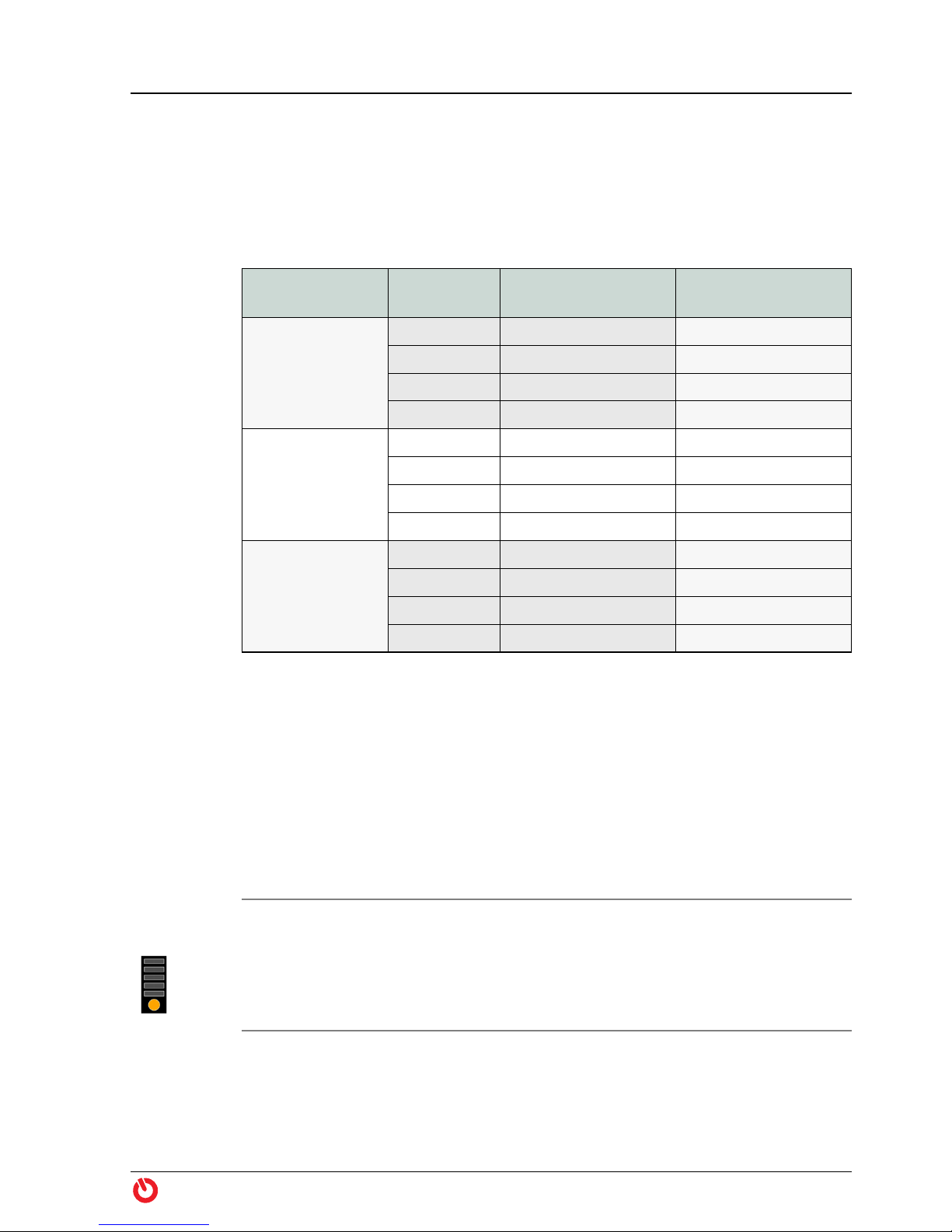
1.7.1 Power Limitation
In order to achieve a largest possible range, the motor power will be limited in
certain support levels (Table 1).
Operation
Riding the Bike
PowerGrip
dotX25
dotX33
dotXUrban
Table 1 Power Limitation
1.7.2 Motor Power
Support
Level
Power1 10 80
Power2 20 180
Power3 30 —
Boost 50 —
Power1 10 180
Power2 20 —
Power3 30 —
Boost 50 —
Power1 7.5 180
Power2 15 —
Power3 22.5 —
Boost 39 —
Torque
[Nm]
Limitation
[W]
While riding, various system parameters are continuously monitored. As the
motor or battery temperature reaches a certain limit, the system automatically
limits the maximum output torque. You may of course continue cycling but you
must make do with reduced motorized assistance. The actual system temperature will be displayed via the PowerGrip’s multicolor LED A (“Status Indicator”
on page 8).
System
heated
maxon BIKEDRIVE | User Manual | rel7971 9
Cause: This is no reason for concern! You are using the BIKEDRIVE for what it
is made for; motorized propulsion while pedaling.
What happens now? Just keep on going!
Depending on driving behavior, topography or usage of «Boost», heating of
motor or battery will possibly further increase and will, eventually, lead to the
status indication «System warm».
Page 10

Operation
Riding the Bike
System warm
Cause: You have pushed the BIKEDRIVE to the maximal permitted
temperature of the motor or the battery.
What happens now? Just keep on going!
The motor will automatically regulate to the highest possible torque output
without exceeding the maximum permitted temperature of the motor or the
battery.
The more you relieve the motor, the sooner you can expect «Boost» and to
return to reach full torque. Thereby, cooling of the battery takes significantly
longer than the cooling of the motor.
1.7.3 Battery Capacity
Among other factors, the operating range per battery charge also depends on
the following influencing factors.
How to get
the most out
of a battery
charge
Running
empty
Shutdown The BIKEDRIVE switches off completely after approximately 15 minutes without
• Gross weight and rolling friction: For example, additionally carried
weight, trailer, low tire pressure, grazing brakes, worn components,
headwind.
• Topography
• Ambient temperature: By principle, the battery can only deliver its
maximum capacity within given temperature limits (Table 6 on
page 38).
• Support level/start-up/acceleration/changing gears: The more you
make use of motorized assistance (thus especially at start-up, during
acceleration, and when climbing a hill), the less your distance and
operating range will be.
Use the gears as with a “normal” bike. Thereby, shift early into a lower
gear when climbing a hill.
You may fully discharge the battery. The internal controller ensures that the
battery does not suffer damage. However, the battery should be recharged
soon thereafter, but no later than within two weeks.
power output. To recommence the motorized ride, restart the BIKEDRIVE
(“Before the Ride” on page 8).
10 maxon BIKEDRIVE | User Manual | rel7971
Page 11

1.8 After the Ride
Operation
After the Ride
If you take a
break:
After the fun
is before the
fun!
Prepare for
transport:
Always turn the BIKEDRIVE completely off whenever you are not sitting on the
bike.
1) Turn the PowerGrip in neutral position «Zero».
2) Turn the BIKEDRIVE off.
Perform the following steps for your BIKEDRIVE to deliver riding pleasure for
many years:
1) Turn the PowerGrip in neutral position «Zero».
2) Turn the BIKEDRIVE off.
3) Clean the bike (page 13).
4) Remove the battery.
5) Remove moisture from motor, PowerGrip, battery, battery rail, and
cables, if any.
6) Charge the battery (page 13)
7) Observe the instructions on battery storage (page 15).
1) Remove the battery and cover the battery rail to protect it from dirt
and humidity.
2) Protect the bike from dirt, dust, rain, snow, salt water, spray water. If
necessary, use transport bag or cover with tarpaulin.
3) Observe the bike manufacturer’s instructions if you intend to remove
the front and/or rear wheel for transport.
4) Observe the following remark on air transportation if you intend to
take your bike along on a flight.
Transport by Air
According to the International Air Transport Association (IATA), lithium batteries with
a capacity exceeding 100 Wh are considered as hazardous goods subject to appropriate conditions for air transport. Carriage on board passenger aircraft is not permitted.
Note that all BIKEDRIVE batteries have a capacity of more than 100 Wh.
Check with your airline or your travel agent on means of transportation before
scheduling a flight.
maxon BIKEDRIVE | User Manual | rel7971 11
Page 12

Operation
After the Ride
••page intentionally left blank••
12 maxon BIKEDRIVE | User Manual | rel7971
Page 13
2MAINTENANCE
The BIKEDRIVE is designed for a demanding off-road use and is extremely
sturdy. Nevertheless, please contact your authorized BIKEDRIVE dealer if any
malfunction should occur.
Please note: You are not entitled to perform any repair on the BIKEDRIVE. It does
not contain any user-serviceable parts.
After appropriate instruction by the specialized dealer you are permitted to
carry out the following described cleaning, inspection, and maintenance work.
Thereby, keep strictly to the instructions and be aware: A manipulation of the
bike that is equipped with a BIKEDRIVE carries a certain danger of getting
injured. Careless or irresponsible behavior or failure to follow the precautionary measures can cause the drive to start.
WARNING
Maintenance
Care & Maintenance
Risk of injury
Work on the bike can lead to serious injury!
Turn off the BIKEDRIVE and remove the battery before you commence with any
work, such as cleaning, maintenance, or troubleshooting!
2.1 Care & Maintenance
2.1.1 After each Ride
Cleaning with Water
Do not expose motor and battery to direct water spray!
1) Clean bike: Remove soiling using a damp rag.
2) Remove moisture: Rub dry motor, battery, cables, and plug connec-
tors with a soft cloth.
WARNING
Risk of injury
You must no longer use visibly damaged batteries. Continued use can lead to
serious injury!
• Remove the damaged battery from the battery rail!
• Do not connect the damaged battery to the battery charger!
• Discard the damaged battery in no case with normal household waste but
only to the appropriate official collection site or via your specialized dealer!
maxon BIKEDRIVE | User Manual | rel7971 13
Page 14
Maintenance
Care & Maintenance
WARNING
Risk of injury
Wrong charging current or penetrating humidity can damage the battery and
can lead to serious injury!
• Use only an original BIKEDRIVE battery charger to recharge the battery!
• During the charging process, protect the battery, battery charger, and plug
• Do not carry out any cleaning or maintenance on the bike while charging is
• Do not leave charger and battery unattended during the charging process!
3) Check for damage: Check motor, battery, cables, and plug connectors
for external damage. Let your authorized BIKEDRIVE dealer replace
any damaged part immediately.
4) Check PowerGrip for ease of movement: It must automatically
bounce back when «Boost» is released. If this is not the case, you have
to dismount and let clean the PowerGrip (page 22).
connectors from contact with humidity (water, dew, cleaning agents, etc.) and
observe the permitted environmental conditions (
on page 35)!
ongoing!
section “3 Technical Data”
5) Charge battery: Choose a cool place to charge the battery. For information on charging temperature and duration see Table 6 on
page 38.
a) Connect battery charger with battery.
b) Connect battery charger to power outlet (100…240 VAC, 50…60 Hz)
and switch on.
c) Switch on battery. The charging process commences. Also observe
the following note «Remarks on the Charging Process».
d) Disconnect battery from battery charger.
e) Disconnect battery charger from power plug.
Remarks on the Charging Process
• The progress of the charging process is indicated by the battery LEDs. Thereby,
the currently level being charged flashes, the already charged levels light up
(
page 33).
• The battery may warm up during charging. If the specified charging temperature
range is exceeded, this is indicated by the battery charge indicator and charging
will be interrupted. After a cooling phase, charging will resume automatically. The
charging time can be prolonged.
• After reaching the full battery charge, the battery automatically shuts off. The
LEDs on the battery go out.
• The amber battery charger LED indicates that the battery charger is connected to
the battery. The LED lights up for the entire duration and after completion of the
charging process.
14 maxon BIKEDRIVE | User Manual | rel7971
Page 15

Maintenance
Care & Maintenance
• The battery charger’s fan may automatically switch on and off during charging.
• If no battery is connected to the charger, the red battery charger LED lights up.
6) Store battery in a cool dry place. For example, do not let the battery
in your car when it is exposed to direct sunlight since it can get
extremely hot in a very short time! Also, observe the permitted environmental conditions (page 38)!
2.1.2 Storage of the Battery
Store the battery in a cool, dry place. For information on the maximum permitted storage temperature see Table 6 on page 38.
Long-term
storage
If you are not using the battery for extended periods, store it at approximately
60% of its capacity. A permanently higher charge will accelerate the principlerelated natural aging of the battery.
2.1.3 Periodic Inspection
In addition to the maintenance specified by the bike manufacturer, you or your
authorized BIKEDRIVE dealer must perform the following inspections.
When? What?
After heavy use
Every 200 km
or
at least annually
Every 1000 km
or
at least annually
When not in use or
for storage:
Every 6 months
Brakes: Check wear on brake discs and brake pads,
replace if necessary
• Rear wheel: Check on specified spoke tension
• Quick-release axle: Check on specified torque
• Screw connections: Check for firm fit
• Plug connections: Check for firm fit
Battery rail: Check for firm fit
Battery: Fully charge the battery and disconnect from
battery charger. Then discharge to approximately 60%
(corresponds to approximately 3 of 5 battery LEDs).
Check the charge periodically and, if necessary, charge
anew and discharge it to 60%.
Table 2 Maintenance Plan
maxon BIKEDRIVE | User Manual | rel7971 15
Page 16

Maintenance
Care & Maintenance
2.1.4 Replacing the rear Brake Disc
BIKEDRIVE axles are available in two designs; with quick-release lever or hexagon socket (Figure 5). For better legibility, in the further course only the quickrelease version (A) will be shown.
Figure 5 Axle versions
2.1.4.1 Dismantling
Remove
cover
IMPORTANT
During disassembly, exposed parts can easily be damaged. Exercise caution.
1) Disconnect motor plug from
Power Cable.
2) Dismantle rear wheel.
3) Loosen and remove screws
(A).
4) Carefully pull off cover (B).
16 maxon BIKEDRIVE | User Manual | rel7971
Page 17

Maintenance
Care & Maintenance
Fold down
cable
Loosen
set screw
Remove
torque lever
5) Carefully fold down cable (C)
by approx. 90°.
6) Loosen set screw (D) about 3
turns (do not remove!).
IMPORTANT
Do not damage cable.
7) Carefully pull off torque
lever (E) in axial direction
from hub by slightly weighing back and forth. Put over
cable and plug and remove.
Remove
brake disc
maxon BIKEDRIVE | User Manual | rel7971 17
8) Loosen and remove screws
(H).
9) Remove spacer plate (G).
10) Carefully pull off brake disc.
Page 18

Maintenance
Care & Maintenance
2.1.4.2 Reassembly
IMPORTANT
• During reassembly, parts can easily be damaged. Exercise caution.
• To attach the brake disc, use only the maxon «Brake Screw Kit TX25», the
• The screws must not axially touch the bottom of the tap. Wrong or too long
originally used, or as to below specified screws.
screws lead to permanent damage of the motor.
Use «Brake
Screw Kit
TX25»
or
check
dimensions
Mount
brake disc
RECOMMENDATION
Use maxon’s «Brake Screw Kit
TX25» (upper illustration).
If you decide not to use the
maxon screw kit:
Make sure that fastening screws
and washers correspond with
the indicated dimensions
(lower illustration)!
1) Check brake disc and hub for
cleanness, clean if necessary.
2) Observe specified brake
disc’s sense of rotation.
3) Slide brake disc (F) on hub,
align radially.
4) Mount spacer plate (G).
5) Mount screws (H) from
«Brake Screw Kit TX25» (for
others, apply medium
strength threadlocker first),
lightly tighten by hand.
18 maxon BIKEDRIVE | User Manual | rel7971
6) Turn brake disc against direction of travel until it strikes
against screws.
7) Tighten screws crosswise
(torque 7 Nm).
Page 19

Maintenance
Care & Maintenance
8) Align cable cutouts of torque
lever (E) and hub.
Mount
torque lever
Mount
set screw
Fold up cable
IMPORTANT
Do not damage cable.
9) Carefully put torque lever in
axial direction over cable
and plug, slide onto hub.
10) Radially align torque lever.
11) Carefully tighten set screw
(D). Do not apply threadlocker!
12) Carefully fold up cable (C) by
approx. 90° and insert into
groove.
Mount cover
13) Place cover (B) on torque
lever and align.
IMPORTANT
The cable must entirely rest in
the groove. It must not protrude
nor be pinched in the separating
pane.
14) Mount screws (A) and lightly
tighten.
15) Check cover for correct fit.
16) Tighten screws crosswise
until parts fully contact.
maxon BIKEDRIVE | User Manual | rel7971 19
Page 20

Maintenance
Care & Maintenance
Install rear
wheel
17) Rotate rear wheel until
torque lever points in direction of travel.
IMPORTANT
Do not damage cable.
18) Carefully position rear wheel
in dropout ans mount as follows:
QR
• Lead axle from left through
the motor’s hollow shaft.
• Align rear wheel, hold tension
nut, and slightly tighten axle.
E-Thru threadless
• Insert tension nut in right
dropout.
• Insert axle from left through
the motor’s hollow shaft.
• Align rear wheel, slightly
tighten axle.
Mount stopper sleeve
E-Thru / Flush / Maxle / X-12
• Screw tension nut in right
dropout, tighten by hand until
stop.
• Insert axle from left through
the motor’s hollow shaft.
• Align rear wheel, slightly
tighten axle.
19) Check condition of scratch
guard (illustration, circle),
replace if necessary.
20) Turn motor against direction
of travel until torque lever
strikes against frame from
below.
21) Tighten axle.
20 maxon BIKEDRIVE | User Manual | rel7971
Page 21

Maintenance
Care & Maintenance
22) Check settings on derailleur
and rear wheel brake pads,
adjust if necessary.
23) Plug Power Cable to motor
plug and lock with bayonet
coupling.
Check
settings
24) Make sure that spring travel
are not restricted by the
cable.
25) Fasten Power Cable (but not
the motor plug!) to the
frame using cable ties.
26) Fasten motor cable to the
frame using «Power Cable
Strip».
maxon BIKEDRIVE | User Manual | rel7971 21
Page 22

Maintenance
Care & Maintenance
2.1.5 Cleaning the PowerGrip
Heavy soiling can keep the PowerGrip from moving freely and can prevent it
from automatically bouncing back when «Boost» is released. In this case you
will need to dismantle and clean the PowerGrip. Your specialized dealer uses
for this purpose the «PowerGrip Service Tool» (533408), a special tool that you
may purchase.
2.1.5.1 Removing the PowerGrip
1) Loosen screw cap and unplug Control Cable from PowerGrip.
2) Loosen mounting screws on PowerGrip (and handlebar grip, if any).
3) Pull off handlebar grip and PowerGrip from handlebar.
2.1.5.2 Dismantling the PowerGrip
IMPORTANT
During disassembly, exposed parts can easily be damaged. Exercise caution.
Hold
PowerGrip
Position
«PowerGrip
Service Tool»
Lift off snapin claws
1) Take the PowerGrip (A) with
one hand.
2) With the other hand, position the «PowerGrip Service
Tool» (B) right-angled at the
PowerGrip.
IMPORTANT
Ensure concentric position of the
parts.
3) Carefully push «PowerGrip
Service Tool» in axial direction between snap-in claws
and twist grip while moving
slightly back and forth at the
same time.
22 maxon BIKEDRIVE | User Manual | rel7971
4) Insert «PowerGrip Service
Tool» up to the stop (approximately 1 mm deep) and hold
in this position.
Page 23

Maintenance
Care & Maintenance
5) Hold firm housing (C).
Remove twist
grip
Align parts
6) Pull off twist grip (D)
together with «PowerGrip
Service Tool» in axial direction from housing.
2.1.5.3 Cleaning
Now, you can clean the individual parts inside and outside:
• Clean housing with damp cloth, wipe dry afterwards.
• Clean twist grip with damp cloth or under running water, wipe dry
afterwards.
2.1.5.4 Reassembling the PowerGrip
1) Align housing and twist grip
as shown.
2) Slide twist grip (D) in axial
Mount twist
grip
Check proper
function
maxon BIKEDRIVE | User Manual | rel7971 23
direction on housing (C).
3) Press together both parts
until they lock with an audible clicking sound.
4) Slightly twist both parts
against one another.
5) Check that twist grip rotates
smoothly and that all snap-in
positions engage easily.
Page 24

Maintenance
Care & Maintenance
2.1.5.5 Mounting the PowerGrip
IMPORTANT
• You will need to shorten the right handlebar grip by about 23 mm if you
• When installed, the PowerGrip must freely rotate. It must thereby
wish both handlebar grips to be of identical lengths.
automatically bounce back when «Boost» is released.
1) Plug Control Cable to PowerGrip and tighten screw cap.
Mount
PowerGrip
and handlebar grip
Fix
PowerGrip
and handlebar grip
2) Slide PowerGrip and handlebar grip on handlebar and
define their axial position.
3) Make sure that handlebar
grip touches the PowerGrip’s inner diameter, mount
plastics spacer if needed.
4) Turn PowerGrip radially into
an ergonomically comfortable position.
5) Cautiously tighten mounting
screws on PowerGrip (and
handlebar grip, if any).
IMPORTANT
The PowerGrip must rotate
freely and must automatically
bounce back when «Boost» is
released.
24 maxon BIKEDRIVE | User Manual | rel7971
Page 25

Maintenance
Care & Maintenance
2.1.6 Spare Parts
Through the combinations of the individual components – motor, freewheel,
end caps, and axle – the BIKEDRIVE can be mounted in a wide range of bike
designs and dropouts. The following overviews point out the possible combinations.
Note that the conversion is only possible within the motor variant. Thus, for
example, the motor «MX25» can be converted from a QR 135 axle to a TA-142
axle, however, a conversion to «MX25B» or «MXUrban» is not possible.
Spare parts are supplied by your specialized dealer.
WARNING
Risk of injury / damage to components
Installing a combination of non-harmonized components can result in serious
injury and damage to the bike!
• It is not permitted to mount a motor «MX25» or «MXUrban» into a Boost
dropout.
• It is not permitted to mount the motor «MX25B» into a standard dropout.
maxon BIKEDRIVE | User Manual | rel7971 25
Page 26

Maintenance
(Table 3)
(Table 3)
Care & Maintenance
2.1.6.1 Compatibility Table
MX25
Figure 6 MX25 | Compatibility of Parts
26 maxon BIKEDRIVE | User Manual | rel7971
Page 27

MX25B
(Table 3)
(Table 3)
Maintenance
Care & Maintenance
Figure 7 MX25B | Compatibility of Parts
maxon BIKEDRIVE | User Manual | rel7971 27
Page 28

Maintenance
(Table 3)
(Table 3)
Care & Maintenance
MXURBAN
Figure 8 MXUrban | Compatibility of Parts
28 maxon BIKEDRIVE | User Manual | rel7971
Page 29

Maintenance
Care & Maintenance
Battery
Motors
MX25
Axle
A B A+B A B A+B
QR 135/10 min. 5 min. 5 10.0…18.6 min. 5 min. 5 10.0…13.6
QR 141/10 min. 5 min. 5 18.2…28.6 min. 5 min. 5 13.2…23.6
Table 3 QR 135/10 — QR 141/10 | Min/Max Frame Dimensions [mm]
2.1.6.2 Spare Parts List
Designation
BX360 ONE 605854
BX500 ONE 582666
Baseplate 515431
Baseplate Plug Cover 535177
MX25-SG-AD-CH500 805005
MX25B-SG-AD-CH500 805008
MXUrban-SG-AD-CH600 623940
MXUrban
MX25B
Order
number
Continued on next page
maxon BIKEDRIVE | User Manual | rel7971 29
Page 30

Maintenance
Care & Maintenance
Rear wheels,
fully fitted:
MX25
MXUrban
Designation
MX25-SG-AD-CH500-260DT01-N01-1KDT02
MXUrban-SG-AD-CH600-260DT01-N01-1KDT02
• Motor: as listed above
• Rim: DT Swiss 533d 26", black
• Spokes: DT Alpine III Ø2.0/1.8/2.34 mm, black, single
crossed
• Spoke nipples: DT Pro Lock Squorx Pro Head, brass
MX25-SG-AD-CH500-275DT01-N01-2KDT02
MXUrban-SG-AD-CH600-275DT01-N01-2KDT02
• Motor: as listed above
• Rim: DT Swiss 533d 27.5", black
• Spokes: DT Alpine III Ø2.0/1.8/2.34 mm, black, dual crossed
• Spoke nipples: DT Pro Lock Squorx Pro Head, brass
MX25-SG-AD-CH500-280DT02-N01-2KDT02
MXUrban-SG-AD-CH600-280DT02-N01-2KDT02
• Motor: as listed above
• Rim: DT Swiss 545db 700c, black
• Spokes: DT Alpine III Ø2.0/1.8/2.34 mm, black, dual crossed
• Spoke nipples: DT Pro Lock Squorx Pro Head, brass
Order
number
607883
607915
607892
607919
607901
607919
Rear wheels,
fully fitted:
MX25B
MX25-SG-AD-CH500-290DT01-N01-2KDT02
MXUrban-SG-AD-CH600-290DT01-N01-2KDT02
• Motor: as listed above
• Rim: DT Swiss 533d 29", black
• Spokes: DT Alpine III Ø2.0/1.8/2.34 mm, black, dual crossed
• Spoke nipples: DT Pro Lock Squorx Pro Head, brass
MX25B-SG-AD-CH500-275DT03-N01-2KDT02
• Motor: as listed above
• Rim: DT Swiss XM 481 27.5", black
• Spokes: DT Alpine III Ø2.0/1.8/2.34 mm, black, dual crossed
• Spoke nipples: DT Pro Lock Squorx Pro Head, brass
MX25B-SG-AD-CH500-275DT04-N01-2KDT02
• Motor: as listed above
• Rim: DT Swiss XM 551 27.5", black
• Spokes: DT Alpine III Ø2.0/1.8/2.34 mm, black, dual crossed
• Spoke nipples: DT Pro Lock Squorx Pro Head, brass
MX25B-SG-AD-CH500-290DT01-N01-2KDT02
• Motor: as listed above
• Rim: DT Swiss 533d 29", black
• Spokes: DT Alpine III Ø2.0/1.8/2.34 mm, black, dual crossed
• Spoke nipples: DT Pro Lock Squorx Pro Head, brass
607906
607921
607909
607911
607912
Continued on next page
30 maxon BIKEDRIVE | User Manual | rel7971
Page 31

Maintenance
Care & Maintenance
PowerGrip
Battery
charger
Axles
(including
adapters)
Quick-
release lever
Hexagon
socket
Designation
PowerGrip dotX25 700025
PowerGrip dotX33 700033
PowerGrip dotXUrban 578492
Power Charger IV 623122
135 mm QR 135/10 (Table 3 on page 29) 512222
141 mm QR 141/10 (Table 3 on page 29) 541057
TA-142/148 E-Thru
TA-142/148 E-Thru threadless
142 mm
148 mm
TA-142/148 Flush
TA-142/148 Maxle
TA-142/148 X-12
Order
number
577735
573911
552063
544929
577736
573913
575894
573908
575893
573907
End caps
HG End Cap Kit 135/141 550001
HG End Cap Kit 142/148 580001
XD End Cap Kit 135/141 550002
XD End Cap Kit 142/148 580002
Continued on next page
maxon BIKEDRIVE | User Manual | rel7971 31
Page 32

Maintenance
Care & Maintenance
Tools
and
Accessories
Designation
Stopper sleeve kit for torque lever 512275
Brake Screw Kit TX25 (for disc brakes) 519904
Brake Screw Kit TX25-CB (for Pedelec-compliant rim brakes) 546336
Control Cable 502867
Control Cable Extension 170 mm 521037
Control Cable Extension 250 mm 521040
Control Cable Extension 2000 mm 578187
Freewheel Kit HG 518374
Freewheel Kit XD 540562
Power Cable Strip 527842
PowerGrip Service Tool 533408
Allen wrench SW 1.27 573138
Table 4 Spare Parts
Order
number
32 maxon BIKEDRIVE | User Manual | rel7971
Page 33

2.2 Troubleshooting
Cause: During shut down or after full discharge of the battery, the
deenergized condition of the motor will briefly be displayed at the
Display on
the
PowerGrip
Display on
the battery
PowerGrip.
Remedy: You do not need to do anything! For safety reasons, the power
supply will first be interrupted to the motor before the entire BIKEDRIVE will
be switched off.
Cause: The PowerGrip has detected an error in the system.
Remedy: Turn BIKEDRIVE off (page 6). Wait for one minute. Turn
BIKEDRIVE on.
Consult your specialized dealer if the error still should persist.
Flashing pattern: The LEDs flash once per second
Cause: Battery is in status «Safety condition overtemperature during
discharge».
Remedy: Turn BIKEDRIVE off (page 6). Wait for 15 minutes. Turn
BIKEDRIVE on.
Flashing pattern: The LEDs flash four times per second
Cause: Battery is in status «Safety shutdown during discharge».
Remedy: Check if battery is charged. Turn BIKEDRIVE off (page 6). Wait for
15 minutes. Turn BIKEDRIVE on.
Maintenance
Troubleshooting
Display on
the battery
Flashing pattern: The LEDs flash every 10 seconds
Cause: Error on the battery.
Remedy: Turn BIKEDRIVE off (page 6). Wait for 15 minutes. Turn
BIKEDRIVE on.
Consult your specialized dealer if the error still should persist.
Running lights: During the charging process, the LEDs display a running light
to the current charging level
Cause: The battery temperature is outside the permitted charging
temperature (Table 6 on page 38).
Remedy: If the ambient temperature is outside the charging temperature,
stop charging and resume at a suitably tempered location.
If the ambient temperature is within the charging temperature, you do not
need to do anything. Charging will continue automatically as soon as the
battery temperature is within the permitted charging temperature.
maxon BIKEDRIVE | User Manual | rel7971 33
Page 34

Maintenance
Disposal
Motor does
not start
Cause: Battery empty.
Remedy: Recharge battery (page 14).
Cause: Main switch turned off.
Remedy: Turn BIKEDRIVE on (page 6).
Cause: Cable defective.
Remedy: Consult your specialized dealer.
Cause: Plug disconnected.
Remedy: Turn BIKEDRIVE off (page 6). Check plug connectors at motor,
battery, cables, and PowerGrip for firm fit. Turn BIKEDRIVE on.
Cause: Motor not correctly initialized.
Remedy: Turn BIKEDRIVE off (page 6). Push bike a step forward. Make sure
that wheels are not blocked. Turn BIKEDRIVE on.
Cause: Power-up with warm motor (for example after changing the battery).
Remedy: Wait 5 to 10 minutes to allow the motor to cool down.
Motor
rotates with
high speed or
in wrong
direction
2.3 Disposal
Cause: Motor not correctly initialized.
Remedy: Turn BIKEDRIVE off (page 6). Push bike a step forward. Make sure
that wheels are not blocked. Turn BIKEDRIVE on.
In no case dispose used components with normal domestic waste!
Dispose disused components only via official collection sites, point of sale, or
your BIKEDRIVE dealer! The sales price includes a prepaid disposal fee allowing
you to let dispose of and recycle disused components free of charge.
34 maxon BIKEDRIVE | User Manual | rel7971
Page 35

3TECHNICAL DATA
The rating plate is located on the left side of the motor (as seen in direction of
travel).
Figure 9 Nameplate (typical)
Technical Data
Motor
Type
Nominal voltage 48 VDC
Output * 500 W500 W600 W
Torque * 26 Nm 26 Nm 19 Nm
Rotational speed * 183 rpm 183 rpm 290 rpm
Efficiency (maximal) 85%
Speed (maximal)
MX25 MX25B MXUrban
Brushless rotary current motor
PowerGrip
dotX25
25 km/h
(15.5 mph)
PowerGrip
dotX33
approx.
30 km/h
(18.6 mph)
PowerGrip
dotX25
25 km/h
(15.5 mph)
PowerGrip
dotX33
approx.
30 km/h
(18.6 mph)
PowerGrip
dotXUrban
approx.
40 km/h
(24.9 mph)
Weight approx. 3.5 kg (including hub)
Dimensions
Environmental
conditions
* according to UNECE regulation No. 85
electronically limited depending on battery voltage
Table 5 Motor MX25 / MX25B / MXUrban | Technical Data
maxon BIKEDRIVE | User Manual | rel7971 35
MX25 Figure 10
MX25B Figure 11
MXUrban Figure 12
Operating temperature −20…+50 °C
Storage temperature −20…+60 °C
Page 36

Technical Data
depending on end cap version
Figure 10 Motor MX25 | Dimensions [mm]
depending on end cap version
Figure 11 Motor MX25B | Dimensions [mm]
36 maxon BIKEDRIVE | User Manual | rel7971
Page 37

Technical Data
depending on end cap version
Figure 12 Motor MXUrban | Dimensions [mm]
maxon BIKEDRIVE | User Manual | rel7971 37
Page 38

Technical Data
Battery
Type
Nominal voltage 48 VDC
Nominal charge 7.5 Ah 10.4 Ah
Nominal capacity 360 Wh 500 Wh
Charging time (0…100%) 2 h 3.5 h
Weight 2.7 kg 2.8 kg
Dimensions (LxWxH) 285x86x120 mm
Environmental
conditions
* with increased charging temperature up to approx. 5.5 h
Table 6 Battery BX360 ONE / BX500 ONE | Technical Data
BX360 ONE BX500 ONE
Lithium-ion battery
Operating temperature
−20…+60 °C −20…+50 °C
Charging temperature
0…+45 °C +10…+40 °C
Storage temperature
0…+30 °C
Figure 13 Battery BX360 ONE / BX500 ONE | Dimensions [mm]
38 maxon BIKEDRIVE | User Manual | rel7971
Page 39

Baseplate
Baseplate
Type
Weight 435 g
Table 7 Baseplate | Technical Data
Battery mount, comprising adapter, base, battery
rail, and Power Cable
Technical Data
Figure 14 Baseplate | Dimensions [mm]
PowerGrip
Type
Weight 56 g
Table 8 PowerGrip | Technical Data
Figure 15 PowerGrip | Dimensions [mm]
PowerGrip
Electronic throttle grip
maxon BIKEDRIVE | User Manual | rel7971 39
Page 40

Technical Data
Battery Charger
Type
Nominal voltage 100…240 VAC, 50…60 Hz
Output voltage 54.6 VDC
Charging current 5 A typical
Weight 1.4 kg
Dimensions (LxWxH) 189x90x65 mm
Operating temperature −10…+40 °C
Environmental
conditions
Table 9 Power Charger IV | Technical Data
Storage temperature: −20…+65 °C
Humidity 5…65% (non-condensing)
Indoor use only
Power Charger IV
Quick charger
Figure 16 Power Charger IV | Dimensions [mm]
40 maxon BIKEDRIVE | User Manual | rel7971
Page 41

Accessories (approximate weights)
QR 135/10 75 g
QR 141/10 81 g
Technical Data
Axles
Quick-release lever
Hexagon socket
End caps
Freewheel Kits
TA-142/148 E-Thru
TA-142/148 E-Thru threadless
TA-142/148 Flush
TA-142/148 Maxle
TA-142/148 X-12
HG End Cap Kit 135/141 13 g
HG End Cap Kit 142/148 16 g
XD End Cap Kit 135/141 13 g
XD End Cap Kit 142/148 16 g
Freewheel Kit HG 100 g
Freewheel Kit XD 85 g
120 g
120 g
125 g
125 g
120 g
120 g
120 g
120 g
120 g
120 g
Control Cable (L=700 mm) 15 g
Control Cable
Extension 170 mm
Cables
Table 10 Accessories | Technical Data
Control Cable
Extension 250 mm
Control Cable
Extension 2000 mm
6 g
7.5 g
56 g
maxon BIKEDRIVE | User Manual | rel7971 41
Page 42

Technical Data
••page intentionally left blank••
42 maxon BIKEDRIVE | User Manual | rel7971
Page 43

Index
Index
A
accessories 32
accessories (technical data) 41
air transport 11
B
Baseplate (battery mount)
technical data 39
battery
charging level 8
discharge 10
storage 15
technical data 38
battery charger (technical data) 40
brake disc, replacement of 16
BX (technical data) 38
C
care 13
charging indicator 8
cleaning 13
components 3
D
dimming (display) 7
discharge of battery 10
displays 7
disposal 34
driving mode
description 4
display 7
F
faults, elimination of 33
functional principle 4
I
IATA (regulations for air transport) 11
identification (PowerGrip) 7
indications used 3
influencing factors (battery charge) 10
inspection, periodic 15
L
labeling 3
legal regulations 4
legislation 4
lock 6
M
main switch 6
maintenance 13
motor
reduced power 9
technical data 35
motorized assistance 4
MX (technical data) 35
N
nameplate 35
O
operating range 10
P
periodic inspection 15
Power Charger (technical data) 40
PowerGrip
cleaning 22
functional principle 5
identification 7
technical data 39
power-up 6
propulsion mode 4
pushing aid 4
R
range 10
reduced motor power 9
references used 3
regulations, legal 4
runtime (battery) 10
S
spare parts 25
status indicator 8
storage 15
switch on/off 6
symbols and signs used 3
T
technical data 35
theft protection 6
tools 32
transport 11
troubleshooting 33
turn off 6
maxon BIKEDRIVE | User Manual | rel7971 43
Page 44

The present document is protected by copyright. Any use (including reproduction, translation,
microfilming, and other means of electronic data processing) without prior written approval is
not permitted. The mentioned trademarks belong to their respective owners and are protected under intellectual property rights.
© 2018 maxon advanced robotics & systems. All rights reserved. Subject to change without
prior notice.
maxon BIKEDRIVE | User Manual | Edition 2018-03 | Document ID rel7971
maxon advanced robotics & systems Ltd..
Industriestrasse 24
CH-6074 Giswil
Switzerland
Phone +41 41 662 95 00 | eMail info@maxonbikedrive.com
 Loading...