

Page 1
1
MM-5500PRO Quick Start Manual
Wireless CDMA 1x EVDO Ethernet modem
Technical Support: engineering@maxon.com.au
TEL : 61 2 9707 2000
FAX : 61 2 9707 3328
www.maxon.com.au
Page 2

2
FCC RF EXPOSURE COMPLIANCE
In August 1996 the Federal Communications Commission (FCC) of the United States with its
action in Report and Order FCC 96-326 adopted an updated safety standard for human
exposure to radio frequency (RF) electromagnetic energy emitted by FCC regulated
transmitters. Those guidelines are consistent with the safety standard previously set by both
U.S. and international standards bodies. The design of this phone complies with the FCC
guidelines and these international standards.
Use only the supplied or an approved antenna. Unauthorized antennas, modifications, or
attachments could impair call quality, damage the phone, or result in violation of FCC
regulations.
This MM-5500PRO Wireless Ethernet modem has been tested for FCC exposure
compliance with the MM-5500PRO wireless ethernet modem form factor. In order to comply
with FCC RF exposure requirements, the MM-5500PRO Wireless Ethernet modem must be
operated with the MM-5500PRO wireless ethernet modem form factor.
The use of this device in any other type of host configuration may not comply with FCC RF
exposure requirements and should be avoided. During operation, a 20cm separation
distance should be maintained between the antenna, whether extended or retracted, and the
user’s/bystander’s body (excluding hands, wrists, feet, and ankles) to ensure FCC RF
exposure compliance.
CAUTION
Change or modification without the express consent of Maxon Electronics Australia Pty. Ltd.
voids the user’s authority to use the equipment. This equipment has been tested and found
to comply with the limits pursuant to Part 22 of the FCC rules. These limits are designed to
provide reasonable protection against harmful interference in an appropriate installation. This
equipment generates, uses, and can radiate radio frequency energy and, if not used in
accordance with instructions, can cause harmful radiation to radio communication. However,
there is no guarantee that interference will not occur in a particular installation. If the
equipment does cause harmful interference in radio and television reception, which can be
determined by turning the equipment on and off, the user is encouraged to try to correct the
interference by one or more of the following measures:
Reorient or relocate the receiving antenna
Page 3

3
Table of Contents
Copyright………………………………………………………………… ………………………………………… …….4
Purpose…………………………………………………………….………………………………………………………4
1. Introduction.………………………………………………….…………………………………………………………5
1.1 MM-5500PRO Overview………………………………………………………………………………….5
1.2 Features……………………….………………………………………………………………………………….5
2. Operation Process……………………………………………………………………………………………………6
2.1 PPP mode……………………………………………………………………………………………………….6
2.2 PPPoE mode…………………………………………………………………………………………………….6
3. Factory Default…………………………………………………………………………………………………………7
3.1 Connecting Internet…….………………………………………………………………………………….7
4. MM-5500PRO Configuration………….………………………………………………………………………..9
5. PPP mode Configuration…………………………………………………………………………………………11
6. PPPoE mode Configuration…………………………………………………………………………………12
7. Firmware Upgrade…………………………………………………………………………………………………21
8. Radius Test………….…………………………………………………………………………………………………22
9. Appendix…………………………………………………………………………………………………………………24
Page 4

4
Copyright
Advance product information describes products which are in development and subject to
development changes. INEWDC has made best effort to ensure that the information contained
in this document is accurate and reliable. This document is the property of INEWDC and implies
no license under patents, copyrights, trade secrets. No part of this publication may be copied,
reproduced, stored in a retrieval system, or transmitted, in any form or by any means
(electronic, mechanical, photographic, or otherwise) without the prior permission of INEWDC .
Purpose
This manual includes how to configure and use the MM-5500PRO.
Page 5

5
1. Introduction
1.1 MM-5500PRO Overview
There are a lot of connections for Internet. Figure 1 shows one of the connectivity on the
internet using a normal ADSL modem.
[Figure 1. Normal Network using an ADSL Modem]
MM-5500PRO is an wireless ethernet modem that supports the connection between LAN
(Local Area Network) to WAN(Wide Area Network) wirelessly in Small Office Home Office.
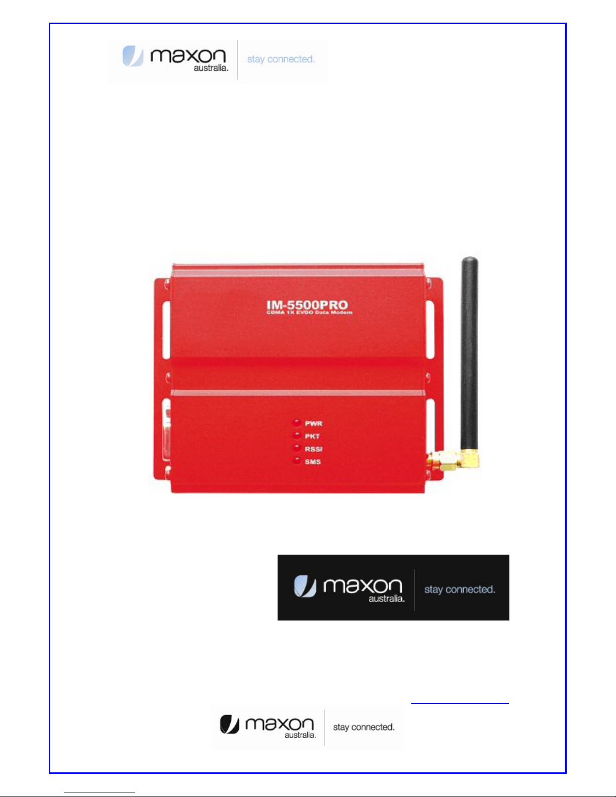
Figure 2 shows the MM-5500PRO’s shape.
[Figure 2. Each part name of MM-5500PRO]
MM-5500PRO supports WAN protocol like PPP, HDLC etc. using CDMA 1x EVDO modem,
routing and bridging functions internally for the high speed data transfer.
1.2 Features
Page 6
6
2. Operation Process
There are two-way of MM-5500PRO operation. One is PPP (Point to Point Protocol) mode
and the other one is PPPoE(PPP over Ethernet) mode.
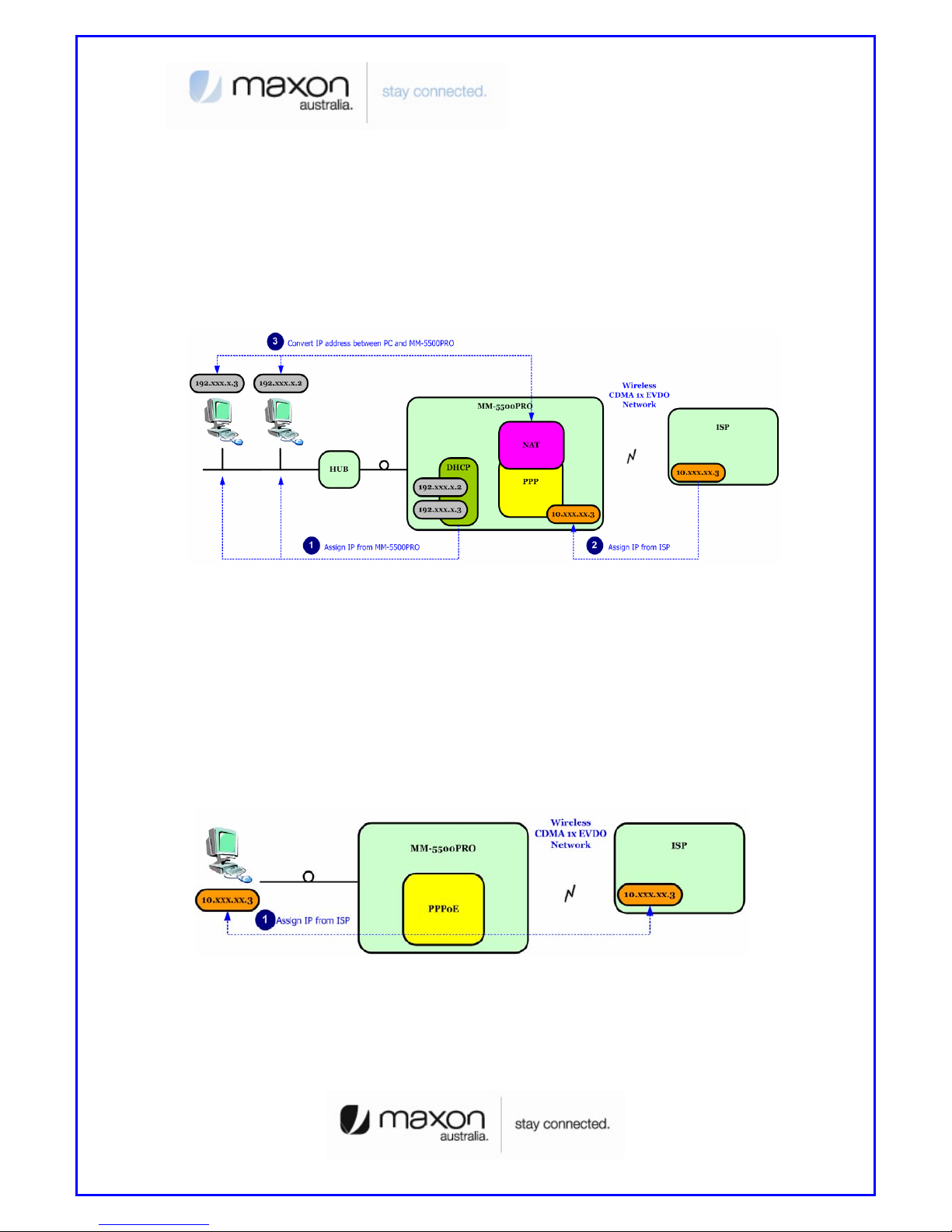
2.1 PPP mode
On PPP mode MM-5500PRO has the IP from ISP (Internet Service Provider) itself, so MM5500PRO can share the IP with many Host PCs. Below figure 3 shows PPP mode operation.
[Figure 3. PPP mode operation]
First, Host PCs get each private IP(hereby IP-1) from MM-5500PRO via DHCP server.
Second MM-5500PRO gets public/Private IP(hereby IP-2) from ISP via CDMA 1x EVDO
modem. Now MM-5500PRO has two kinds of IP, one is from ISP and the other ones are to
Host PCs. Third, MM-5500PRO convert network data between IP-1 and IP-2 via NAT.
2.2 PPPoE mode
On PPPoE mode MM-5500PRO has no IP, just the Host PC gets IP from ISP.
[Figure 4. PPPoE mode operation]
Different on PPP mode, the IP from ISP goes to Host PC directly. MM-5500PRO
converts protocol from PPP to PPPoE or on reverse direction, the Host PC processes all
network protocols.
Page 7
7
3. Factory Default
MM-5500PRO is already set for normal operation. So just connect between PC and MM5500PRO. Check the network environment of Host PC.
3.1 Connecting Internet
For accessing Internet, should obtain IP automatically so refer below steps.
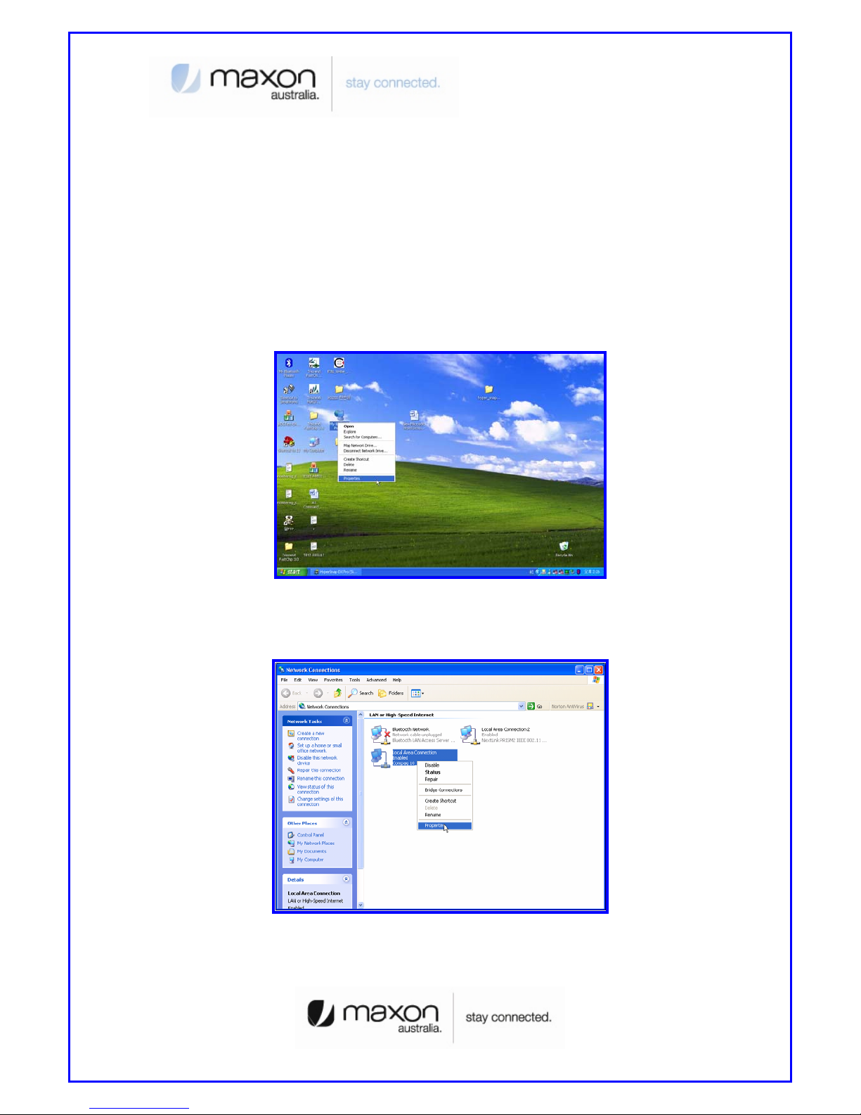
(1) Assumed the user uses the Windows XP. For connect between PC and MM-5100PRO,
click “My Network Places” choose the [properties].
[Figure 5. First step of setting the Host PC]
(2) Check the “Local Area Connection”, click the mouse right button then [Properties].
[Figure 6. Second step of setting the Host PC]
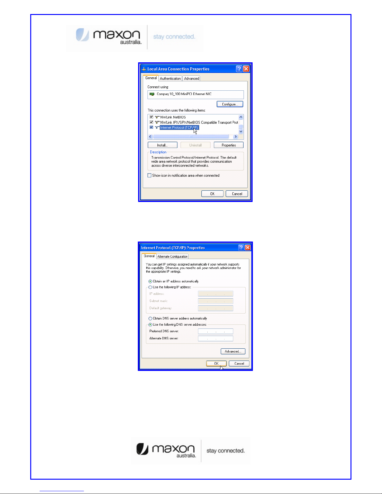
(3) Chose “Internet Protocol [TCP/IP]” Tab and double click the item.
Page 8
8
[Figure 7. Third step of setting the Host PC]
(4) Check the “Obtain an IP address automatically” then click the [OK] button.
[Figure 8. Forth step of setting the Host PC]
(5) Host PC’s setting is finished. Connect Power and Ethernet cable on MM-5500PRO. Wait
for about 10 seconds or until the LED of PKT blinks. Connect your PC on Internet.
Page 9
9
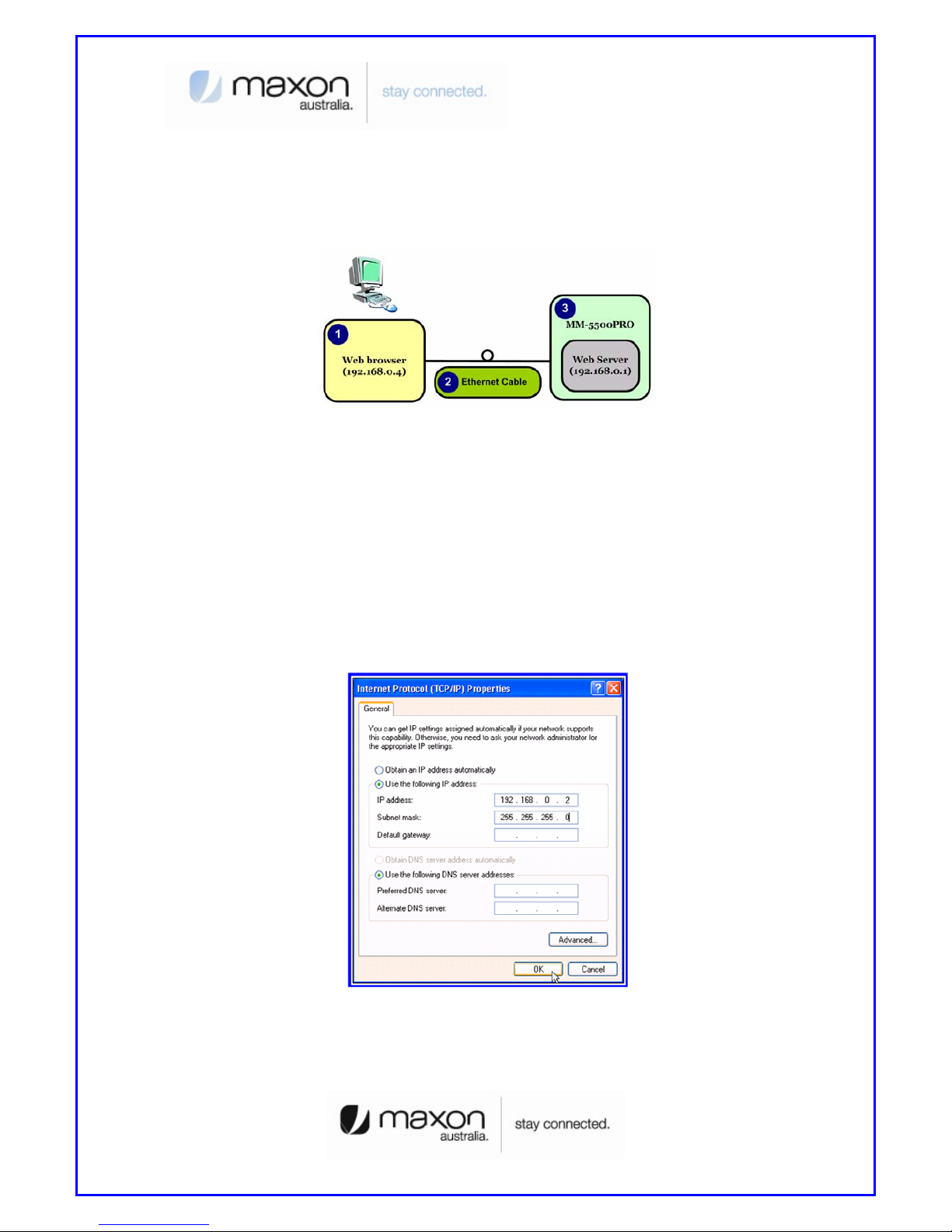
4. MM-5500PRO Configuration
User can change the function of MM-5500PRO by configuring it for user’s purpose. Supports
the web based configuration pages for simplified installation and setup. Figure 9 shows
connection on MM-5500PRO’s configuration.
[Figure 9. Configuration of MM-5500PRO]
(1) Connect Power cable on MM-5500PRO.
(2) Connect LAN cable between Host PC and MM-5500PRO.
(3) Set Host PC network environment below.
- Host PC IP : 192.168.0.2(except 1: 1 is MM-5500PRO)
- Subnet mask : 255.255.255.0
- DNS : (omit)
Figure 10 shows the window of Internet Protocol(TCP/IP) Properties.
(if don’t know how to find below window, go to page 5)
[Figure 10. Setting Host PC]
(4) Start web browser like Internet explore then write IP address, 192.168.0.1 (by default)
for connecting web page of configuration in MM-5500PRO.
Page 10
10
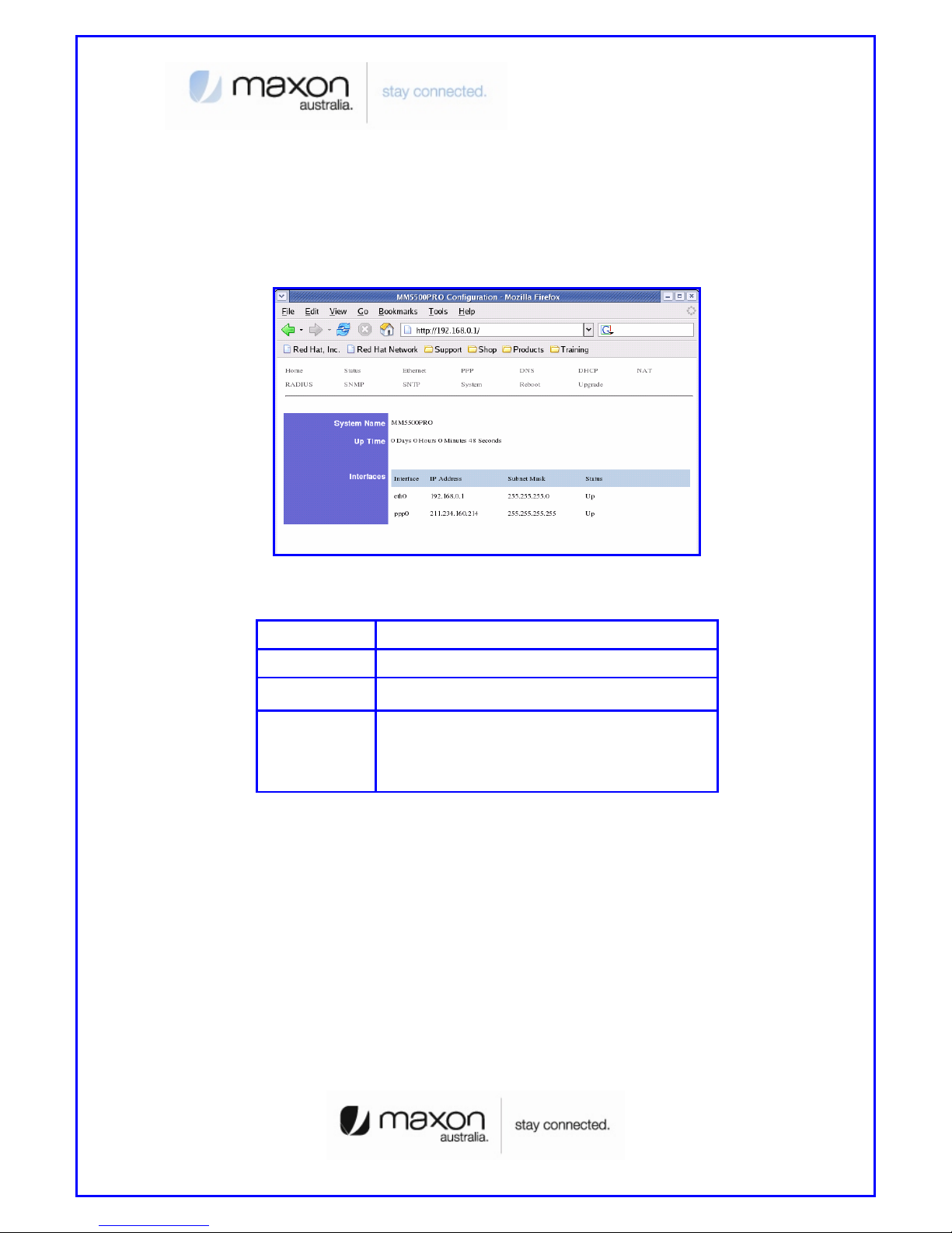
(5) The pop-up window of login page appears like figure 11.
- User name: admin
- Password: admin
(6) “Home” page shows the system information of MM-5500PRO.
[Figure 11. Home Page]
ITEM Description
System Name Product Name
Up Time Operation time from power on
Interface
eth0 : Status of Ethernet0 IP
ppp0 : Status of CDMA0 IP
(After getting IP from ISP, this IP appears)
(7) We saw the connecting web page of configuration in MM-5500PRO, now try to set each
configurations for each mode.
Page 11
11
5. PPP mode Configuration
We assume that MM-5500PRO current mode is not PPP mode in this chapter.
(1) Connect Power cable on MM-5500PRO.
(2) Follow the chapter 4, connect MM-5500PRO’s configuration web page.
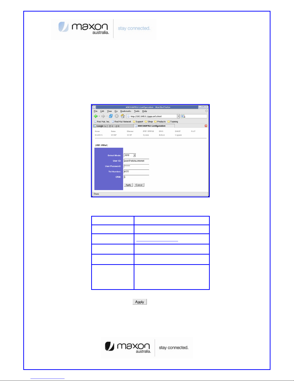
(3) Click “PPP/PPPOE” menu then PPP/PPPOE page appears like figure 12.
[Figure 12. PPP/PPPOE Page]
ITEM Description
Select Mode PPP
User ID user@telstra.internet (or others)
User Password Password
Tel Number #777
CRM
1 : 1x, EVDO (By default)
150 : 1x only
160 : EVDO only
(4) All setting finished then Click the
button.
(5) Disconnect power cable then reconnect it.
(6) Follow the chapter 3, change the Host PC’s network environment.
(7) Execute web browser and explore internet.
Page 12

12
6. PPPoE mode Configuration
We assume that MM-5500PRO current mode is not PPPoE mode in this chapter.
(1) Connect Power cable on MM-5500PRO.
(2) Follow the chapter 4, connect MM-5500PRO’s configuration web page.
(3) Click “PPP/PPPOE” menu then PPP/PPPOE page appears like figure 13.
[Figure 13. PPP/PPPOE Page]
ITEM Description
Select Mode PPPoE
User ID Not effect
User Password Not effect
Tel Number Not effect
CRM
1 : 1x, EVDO (By default)
150 : 1x only
160 : EVDO only
(4) All setting finished then Click the
button.
(5) Disconnect power cable then reconnect it.
(6) Follow the chapter 3, change the Host PC’s network environment.
Page 13

13
(7) In this example we assumed the user uses the Windows XP. If it is not Windows XP, the
user should install PPPoE connection application program. For connect between PC and
MM-5500PRO click the “My Network Places” choose the [properties].
[Figure 14. First step of setting the Host PC]
(8) Check the “Local Area Connection”, click the mouse right button then [Properties].
Page 14

14
[Figure 15. Second step of setting the Host PC]
(9) Chose Internet Protocol[TCP/IP] Tab and double click the item.
[Figure 16. Third step of setting the Host PC]
(10) Check the “Obtain an IP address automatically” then click the [OK] button.
Page 15

15
[Figure 17. Forth step of setting the Host PC]
(11) You should make PPPoE connection so click the “Create a nee connection”
[Figure 18. First step of creating a PPPoE connection]
(12) New Connection Wizard appears, click [Next] button.
Page 16

16
[Figure 19. Second step of creating a PPPoE connection]
(13) Check “Connect to the Internet” then click [Next] button.
[Figure 20. Third step of creating a PPPoE connection]
(14) Check “Set up my connection manually” then click [Next] button.
Page 17

17
[Figure 21. Forth step of creating a PPPoE connection]
(15) Check “Connect using a broadband connection that requires a user name and
password” then click [Next] button.
[Figure 22. Fifth step of creating a PPPoE connection]
Page 18

18
(16) Write the ISP Name what you want. In this example write ISP name then click [Next]
button.
[Figure 23. Sixth step of creating a PPPoE connection]
(17) Write User name/Password/Confirm password what you use. Then click [Next] button.
[Figure 24. Sixth step of creating a PPPoE connection]
Page 19

19
(18) All setting is finished, check “Add a shortcut to connection and close this wizard, click
Finish” then click [Finish] button.
[Figure 25. Seventh step of creating a PPPoE connection]
(19) PPPoE connection program appears then click [Connect] button.
[Figure 26. PPPoE connection application program]
Page 20

20
(20) Connecting window appears, trying to connect MM-5500PRO.
[Figure 27. Connecting between PC and MM-5500PRO]
(21) After connection between PC and MM-5500PRO, then go to the verifying stage.
[Figure 28. Verifying username and password]
(22) Changing Registering stage, the Host PC connecting on the network.
[Figure 29. Registering PC on the network]
(23) Click the [Start] button then choose Internet Explorer.
Page 21

21
[Figure 30. Starting Internet Explorer]
7. Firmware Upgrade
Firmware is for MM-5500PRO. When the firmware is to be upgrade or to be download, use
like this.
(1) Connect Power cable on MM-5500PRO.
(2) Follow the chapter 4, connect MM-5500PRO’s configuration web page.
(3) Click “Upgrade” menu then PPP/PPPOE page appears.
(4) Click the
button and search the firmware file.
(5) Select the firmware file then “OK”.
Page 22

22
[Figure 31. Firmware Upgrade]
(6) Click the
button then below Figure 31 appears.
[Figure 32. Firmware Upgrade finished]
(7) Execute web browser and explore internet.
8. Radius Test
There is no needed RADIUS on normal using wireless AP but if connect user PC using RADIUS
protocol, there are some needed to define below.
(1) Wireless AP supports RADIUS protocol to communicate with MM-5500PRO.
(2) ISP(Internet Service Provider) supports subnet mask 255.255.255.xxx (because Client
PCs should get their IP from RADIUS Server).
(3) RADIUS Client Software is installed on Client PC.
Page 23

23
(4) Get the RADIUS Server information including Authentication Server IP/Port and
Accounting Server IP/Port.
(5) IP of MM-5500PRO should be registered in advance.(But now MM-5500PRO gets
Dynamic IP from ISP so after get the IP from MM-5500PRO then let the RADIUS server
know the MM-5500PRO’s IP. In the future if MM-5500PRO using RADIUS protocol, MM5500PRO needed Static IP from ISP).
[Figure 33. RADIUS Authentication and Accounting Network]
(6) Connect Power cable on MM-5500PRO.
(7) Follow the chapter 4, connect MM-5500PRO’s configuration web page.
(8) Click “RADIUS” menu then RADIUS page appears.
Page 24

24
[Figure 34. RADIUS Setting Page]
ITEM Description
Authentication Server
Server IP : xxx.xxx.x.x
Server Port : xxxx
Shared Secret : depend on Authentication Server
Accounting Server
Server IP : xxx.xxx.x.x
Server Port : xxxx
Shared Secret : depend on Authentication Server
Server Timeout Second of time out (depend on network speed)
Max.Request Time of Request (normal 2~3 times)
Session Timeout Default by server
Idle Timeout Default by server
Interim Interval Default by server
(9) All setting finished, execute the RADIUS Client Software that is installed on Client PC
then connect on Internet.
Page 25

25
9. Appendix
Below pages are descriptions of other configuration pages.
(1) “Status” page shows current protocol status.
[Figure 35. Status Page]
ITEM Description
Select Statistics
Information of Target
- Device
- ARP
- IP
- ICMP
- TCP
- UDP
- ROUTE
Page 26

26
Device Statistics Each status & Information
(2) “Ethernet” page shows the information of Ethernet interface.
[Figure 36. Ethernet Page]
ITEM Description
Connect Type
Static: Should be Always
(Dynamic: Will be omit)
IP Address eth0 IP
Subnet Mask Subnet mask IP Address
Gateway Gateway Address
DHCP Hostname (Will be omit)
Page 27

27
(3) “PPP” page shows the information of PPP authentication.
[Figure 37. PPP Page]
ITEM Description
User ID Received ID from ISP
User Password Password
Tel Number Calling number
(4) “DNS” page shows the information of setting DNS IP Address.
[Figure 38. DNS Page]
Page 28

28
ITEM Description
1st DNS IP Address First DSN IP (Optional)
2nd DNS IP Address Second DSN IP (Optional)
(5) “DHCP” page shows the information of setting DHCP.
[Figure 39. DHCP Page]
ITEM Description
Activate Enable/Disable: DHCP server on-off
Start IP Address Start address local IP(start range)
End IP Address End address local IP(End range)
Subnet Mask Subnet mask IP Address
Default Lease Time Default Time of assigning IP
Max Lease Time Maximum Time of assigning IP
Default Gateway Gateway IP Address
Page 29

29
(6) “NAT” page shows the information of setting NAT.
[Figure 40. NAT Page]
ITEM Description
Operation Enable/Disable: NAT on-off
Virtual Sever User can select/configure NAT option
Access Control End address local IP(End range)
DMZ Host IP Setting DMZ Host IP Address
VPN Pass-Through IP VPN IP Address
Page 30

30
(7) “RADIUS” page shows the information of setting RADIUS.
[Figure 41. RADIUS Page]
ITEM Description
Server IP Authentication Server IP & Port
Shared Secret RADIUS Secret Key
Server IP Accounting Server IP & Port
Shared Secret Accounting Secret Key
Server TimeOut Waiting Time of Accounting Server
Max Request Repeat time of accounting request
Session Timeout Available time of session status
Idle Timeout Available time of Idle status
Page 31

31
Interim Interval Frequent time of accounting packet
(8) “SNMP” page shows the information of setting SNMP.
[Figure 42. SNMP Page]
ITEM Description
Activate Enable/Disable
Read Community Name Setting Reading authority
Write Community Name Setting Writing authority
System Name Setting system name
System Contact Setting system contact
System Location Setting system location
Trap Community Name Setting Trap community
Page 32

32
1
st
Trap Server IP Setting 1st Trap Server IP
2nd Trap Server IP Setting 2nd Trap Server IP
Auth. Fall Trap Warning message to Trap server
Cold Start Trap First booting message to Trap server
Link UP Trap Normal status message to Trap server
Link Down Trap Abnormal status message to Trap serv er
(9) “SNTP” page shows the information of setting SNTP.
[Figure 43. SNTP Page]
ITEM Description
Operation Enable/Disable: SNTP on-off
SNTP Sever Address Setting SNTP server
Time Zone Setting SNTP time zone
Page 33

33
(10) “System” page shows the information of System.
[Figure 44. System Page]
ITEM Description
Admin Name Name of Administrator
Admin Password Setting Admin password
HTTP Port HTTP Port number
Telnet Daemon Enable/Disable Telnet
(11) “Reboot” page makes MM-5500PRO reboot.
Page 34

34
[Figure 45. Reboot Page]
ITEM Description
Reboot System Reboot MM-5500PRO
(All document finished)
Page 35

35
Thank you.
 Loading...