

Page 1
Document Number: 181-03001
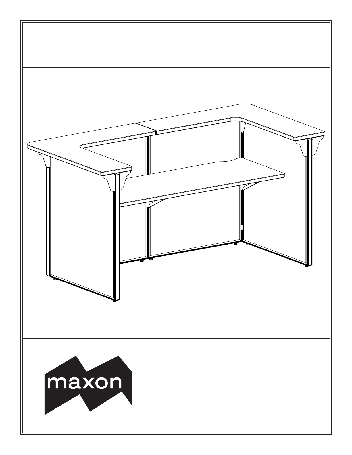
®
Revision Date: November 2008
Maxon Furniture Inc.
An operang company of the HNI Corporaon
www.maxonfurniture.com
Customer Service 1-800-876-4274
M-KIT100/101/102
Assembly Instructions
These instrucons must be followed exactly. Failure to
follow these instrucons could damage the product or
result in injury to persons using or assembling the product.
Maxon Furniture Inc. shall not be liable for any costs, loss,
damage, expenses or injuries resulng from failure to
properly assemble the product in accordance with these
instrucons.
Page 2
Maxon Furniture Inc. Customer Service: 1-800-876-4274
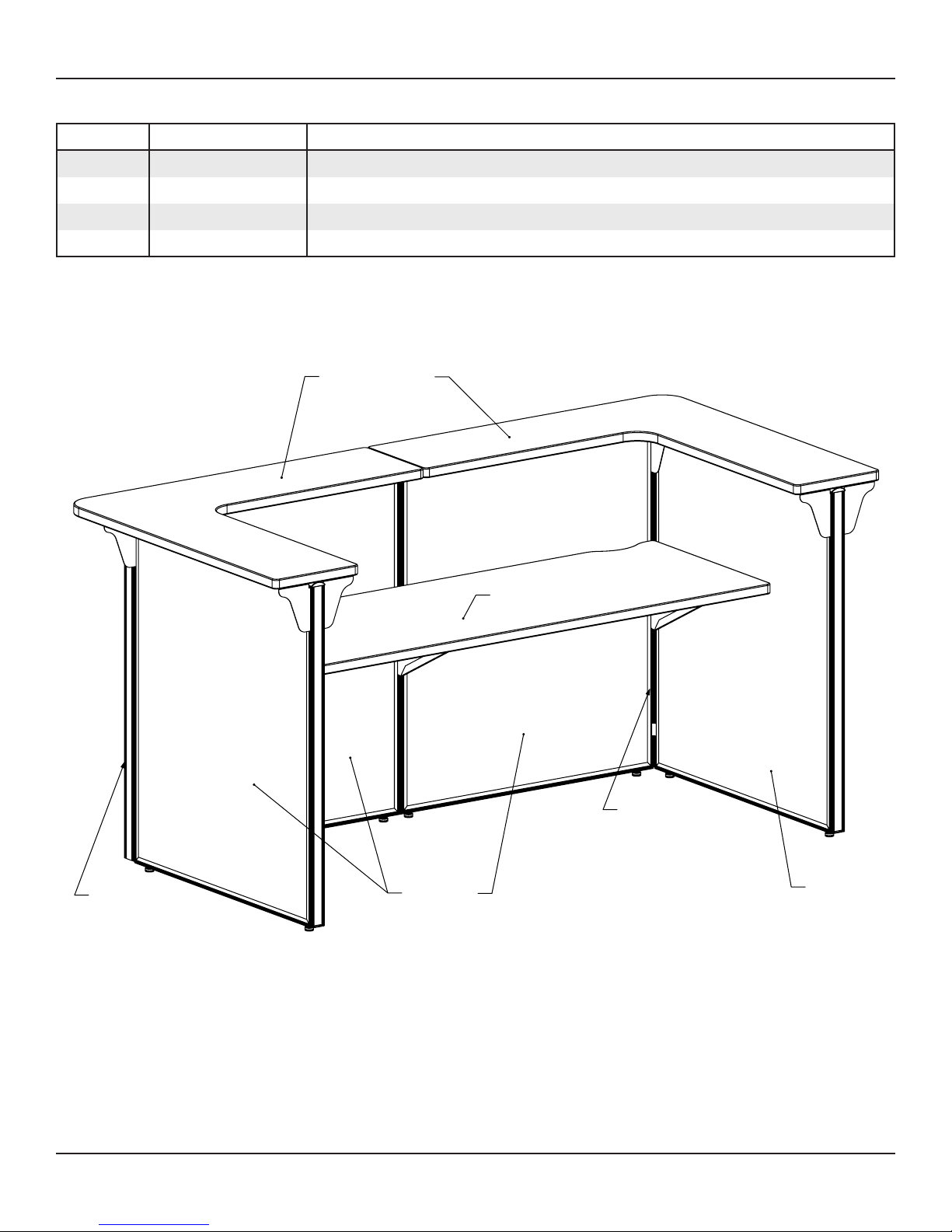
Quanty Part Number Descripon
4 PLNR4236 Non-Raceway Panel, 42H x 36W
2 PLNRCP42 Corner Post Kit, 42” High
2 LCCT123636TM Corner Countertop, 12D x 36W x 36W
1 UWR2472TM Rectangular Worksurface, 24D x 72W
*
The Worksurface carton contains two RH and one LH Canlevers screwed to the worksurface.
LCCT123636TM
*
UWR2472TM
PLNRCP42
PLNRCP42
PLNR4236
PLNR4236
For installaon assistance or to report missing parts, please contact Customer Service at 1-800-876-4274
These instrucons must be followed exactly. Failure to follow these instrucons could damage the product or result in injury to persons using or
assembling the product. Maxon Furniture Inc. shall not be liable for any costs, loss, damage, expenses or injuries resulng from failure to properly
assemble the product in accordance with these instrucons.
Page 2 of 10 M-KIT100/101/102 Assembly Instrucons 181-03001
Page 3
Maxon Furniture Inc. Customer Service: 1-800-876-4274
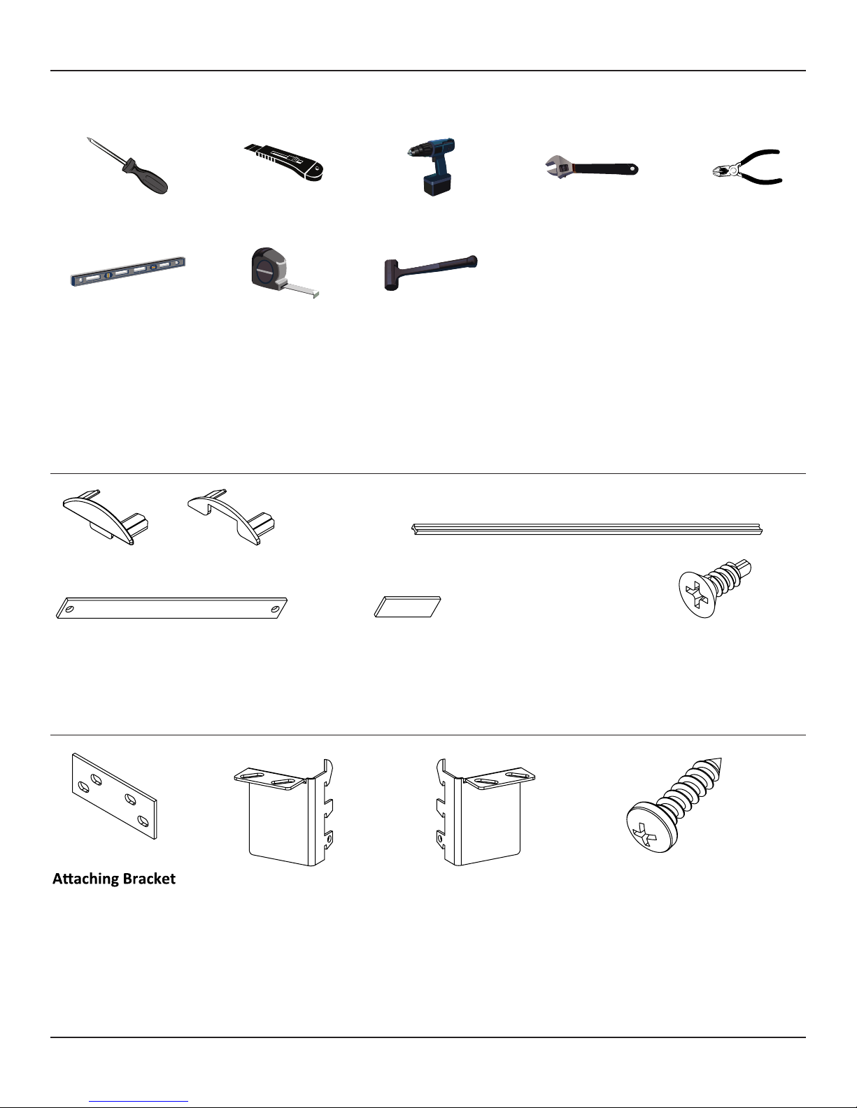
Tools Required for Assembly
Phillips Screwdriver
Boxcuer
Drill/Screw Gun
with Phillips bit
1/2” Box End or
Adjustable Wrench
Wire Cuers
Level
Tape Measure
Rubber Mallet
Hardware Kits
Please ensure all required pieces are present before beginning assembly. Some steps may require a second
person for assistance.
Panel Hardware (PLNR4236)
End Cap
Provided: 4
Used: 2
Lock Bar
Provided: 4
Used: 1
Top Cap Spacer
Provided: 4
Used: 2
I-Beam Panel Connector
Provided: 24
Used: 24
Straight Alignment Bracket
Provided: 4
Used: 1
#8 x 1/2" Phillips Flat Head
Provided: 8
Used: 2
Rectangular Worksurface Hardware (UWR2472TM)
RH Corner Bracket
Provided: 1
Used: 0
These instrucons must be followed exactly. Failure to follow these instrucons could damage the product or result in injury to persons using or
assembling the product. Maxon Furniture Inc. shall not be liable for any costs, loss, damage, expenses or injuries resulng from failure to properly
assemble the product in accordance with these instrucons.
Page 3 of 10 M-KIT100/101/102 Assembly Instrucons 181-03001
Provided: 1
Used: 0
LH Corner Bracket
Provided: 1
Used: 0
#10 x 3/4" Pan Head Screw
Provided: 16
Used: 9
Page 4

Maxon Furniture Inc. Customer Service: 1-800-876-4274
Hardware Kits
Corner Post Hardware (PLNRCP42)
Top Cap Spacer
Provided: 6
Used: 0
Straight Alignment Bracket
Provided: 2
Used: 2
I-Beam Panel Connector
Provided: 12
Used: 6
Angle Alignment
Bracket
Provided: 6
Wedge Bracket
Provided: 6
Used: 4
Corner Post Cap
Provided: 2
Used: 2
Used: 2
Brackets are shipped
in strips of 3 - break
apart before using.
Corner Countertop Hardware (LCCT123636TM)
Provided: 4
Used: 2
These instrucons must be followed exactly. Failure to follow these instrucons could damage the product or result in injury to persons using or
assembling the product. Maxon Furniture Inc. shall not be liable for any costs, loss, damage, expenses or injuries resulng from failure to properly
assemble the product in accordance with these instrucons.
Provided: 6
Used: 5
LH Countertop Bracket
RH Countertop Bracket
Provided: 6
Used: 5
#10 x 3/4" Pan Head Screw
Provided: 32
Used: 28
Page 4 of 10 M-KIT100/101/102 Assembly Instrucons 181-03001
Page 5

Maxon Furniture Inc. Customer Service: 1-800-876-4274
I-Beam Panel Connectors
Installing the Panels
Top Cap
PLNRCP42
Corner Post
Slide/pry the Top Cap from each PLNR4236 1.
Panel, being careful not to damage the parts
(Figure 1).
Figure 1
CAUTION! The following steps may require
assistance to complete.
PLNR4236
Panel end
Panel
PLNR4236
Panel
Posion the PLNR4236 Panels in their 2.
approximate installed placement and level by
turning the Glides on the boom of the Panel
Frame with a 1/2 inch wrench.
Corner
Post
Figure 2
On one PLNR4236 Panel, insert one Straight 3.
Alignment Bracket into the notch located on
the PLNR4236 Panel’s edge at the boom of
the PLNR4236 Panel frame (Figure 2).
Place one PLNRCP42 Corner Post on top of 4.
the Straight Alignment Bracket.
Connect the PLNRCP42 Corner Post to the 5.
PLNR4236 Panel by sliding plasc I-Beam
Panel Connectors down the grooves in
Angle Alignment
Bracket
Straight Alignment
Bracket
Figure 3
TOP VIEW
Glide
between the PLNRCP42 Corner Post and the
PLNR4236 Panel’s edge (Figure 3).
TIP! Use 3 I-Beam Panel Connectors in
each groove.
Using wire cuers or snips, trim the excess 6.
I-Beam Panel Connector length so that the
grooves are completely lled and ush with
the PLNR4236 Panel frame top.
INTERIOR
90
ASSEMBLED VIEW
Figure 4
Angle
Alignment
Bracket
These instrucons must be followed exactly. Failure to follow these instrucons could damage the product or result in injury to persons using or
assembling the product. Maxon Furniture Inc. shall not be liable for any costs, loss, damage, expenses or injuries resulng from failure to properly
assemble the product in accordance with these instrucons.
I-Beam Panel
Connectors
Place one PLNR4236 Panel against the 7.
PLNRCP42 Corner Post at a 90° angle from the
rst PLNR4236 Panel (creang an L-shape).
Insert one Angle Alignment Bracket (Figure 2 8.
& Figure 4) into the slots of the two PLNR4236
Panels being connected.
Tip! Use two slots near the boom to
help eliminate interference with future
accessory installaons.
Page 5 of 10 M-KIT100/101/102 Assembly Instrucons 181-03001
Page 6

Maxon Furniture Inc. Customer Service: 1-800-876-4274
Figure 5
Figure 6
Panel Connectors
#8 x 1/2" Phillips
Flat Head Screw
Lock Bar
Straight Alignment
Bracket
TOP VIEW
#8 x 1/2" Phillips
Flat Head
While holding the Angle Alignment Bracket in 9.
place, connect the second Panel by inserng
the I-Beam Panel Connectors as directed in
Steps 5-6.
Add one PLNR4236 Panel to the L-shape by 10.
inserng one Straight Alignment Bracket
between the adjoining PLNR4236 Panels and
connecng with the I-Beam Panel Connectors
(Figure 5).
Trim the excess I-Beam Panel Connector 11.
length with wire cuers or snips as directed
in Step 6.
TIP! Leveling the panels by adjusng
the Glides may ease the I-Beam Panel
Connector installaon.
To secure the PLNR4236 Panels, center the 12.
Lock Bar over two PLNR4236 Panels (Figure
5) and aach with two #8 x 1/2” Flat Head
Self Drilling Screws (Figure 6).
Repeat Steps 3 - 6 to aach the remaining 13.
PLNRCP42 Corner Post to the assembled
PLNR4236 Panels (Figure 7).
Lock Bar centered
over panels.
Repeat Steps 7 - 9 to aach the remaining 14.
PLNR4236 Panel. This completes the
installaon of the PLNR4236 Panels.
Figure 7
Corner
Post
PLNR4236
Panel
These instrucons must be followed exactly. Failure to follow these instrucons could damage the product or result in injury to persons using or
assembling the product. Maxon Furniture Inc. shall not be liable for any costs, loss, damage, expenses or injuries resulng from failure to properly
assemble the product in accordance with these instrucons.
Page 6 of 10 M-KIT100/101/102 Assembly Instrucons 181-03001
Page 7

Maxon Furniture Inc. Customer Service: 1-800-876-4274
Installing Panel Trim
Wedge
Brackets
Figure 8
Figure 9.a
Figure 9.b
End Cap
(2 places)
TOP VIEW
Spacer Cap
(2 places)
Corner Post
Cap
(2 places)
Wedge Bracket
(4 places)
Install metal Wedge Brackets at all panel-1.
to-corner-post connecons by inserng the
Wedge Bracket ange between the PLNR4236
Panel and the PLNRCP42 Corner Post (Figure
8).
TIP! Four Wedge Brackets will be
installed.
Install one Corner Post Cap onto the two 2.
PLNRCP42 Corner Posts (Figure 9.a).
TIP! Two Corner Post Caps will be
installed.
Install one End Cap into the two PLNR4236 3.
Return Panel Top Caps (Figure 9.b).
Snap the two Top Caps onto the two PLNR4236 4.
Return Panels.
TIP! The End Cap tab should t into the
Panel frame.
Install one Top Cap Spacer into the end of 5.
each of the other two Top Caps (Figure 9.a).
Snap the two Top Caps onto the two 6.
PLNR4236 Panels with the Spacer end next to
Top Cap
Spacer Cap
Corner
Post
Cap
PLNR4236
Return
Panel
PLNR4236
Return
Panel
These instrucons must be followed exactly. Failure to follow these instrucons could damage the product or result in injury to persons using or
assembling the product. Maxon Furniture Inc. shall not be liable for any costs, loss, damage, expenses or injuries resulng from failure to properly
assemble the product in accordance with these instrucons.
the PLNRCP42 Corner Posts.
End Cap
Page 7 of 10 M-KIT100/101/102 Assembly Instrucons 181-03001
Page 8

Maxon Furniture Inc. Customer Service: 1-800-876-4274
Adding the Countertops
Figure 10
FRONT VIEW
LCCT123636TM
Countertop
PLNR4236
Return
Panel
LH
Countertop
Bracket
RH
Countertop
Bracket
PLNR4236
Return
Panel
Unpack the two LCCT123636TM Countertop 1.
boxes and hardware kits.
TIP! Lay the Countertops on a so surface
unl you are ready to install them.
Place LH and RH Countertop Brackets into the 2.
Panel Slots on the end of a PLNR4236 Return
Panel (Figure 10).
Posion Corner Countertop on the Panels 3.
and align with Brackets.
Aach LH and RH Countertop Brackets to 4.
Countertops with two #10 x 3/4” Pan Head
Screws, installing the screw closest to the
panel rst.
ATTENTION! DO NOT completely ghten
the screws to allow for adjustment.
While ghtening the #10 x 3/4” Pan Head 5.
Screws, pull the RH and LH Countertop
Brackets up in the slots unl they are ush
with the top of the PLNR4236 Return Panels.
TIP! Make sure Bracket teeth are fully
engaged in Panel slots.
Repeat Steps 1-5 to install the second 6.
LCCT123636TM Countertop.
These instrucons must be followed exactly. Failure to follow these instrucons could damage the product or result in injury to persons using or
assembling the product. Maxon Furniture Inc. shall not be liable for any costs, loss, damage, expenses or injuries resulng from failure to properly
assemble the product in accordance with these instrucons.
Page 8 of 10 M-KIT100/101/102 Assembly Instrucons 181-03001
Page 9

Maxon Furniture Inc. Customer Service: 1-800-876-4274
BACK VIEW
Figure 11
Attaching
Bracket
(use 2 Brackets,
1 on each side
of the panels)
Attach the inside screw
first to help ensure Bracket
teeth are fully engaged
in the panel slots.
#10 x 3/4"
Phillips
Pan Head
Screw
Adjust and align LCCT123636TM Countertops 7.
to PLNR4236 Panels.
Connect LCCT123636TM Countertops 8.
together using two Aaching Brackets (1 on
each side of the PLNR4236 Panels) and four
#10 x 3/4” Pan Head Screws per Bracket
(Figure 11).
Aach one pair of LH and RH Countertop 9.
Brackets to each Countertop on the outside
corner of the workstaon with two #10 x 3/4”
Pan Head Screws per Bracket (Figure 12).
Aach one LH and RH Bracket to the inside 10.
corners of the workstaon with two #10 x
3/4” Pan Head Screws per Bracket (Figure
13).
Fully ghten all screws when LCCT123636TM 11.
Countertops are aligned with each other and
the PLNR4236 Panels.
LH & RH Countertop
Brackets
These instrucons must be followed exactly. Failure to follow these instrucons could damage the product or result in injury to persons using or
assembling the product. Maxon Furniture Inc. shall not be liable for any costs, loss, damage, expenses or injuries resulng from failure to properly
assemble the product in accordance with these instrucons.
Page 9 of 10 M-KIT100/101/102 Assembly Instrucons 181-03001
LH & RH
Countertop
Brackets
Figure 13Figure 12
LH Countertop
Bracket (hidden)
RH Countertop
Bracket
Page 10

Maxon Furniture Inc. Customer Service: 1-800-876-4274
Adding the Worksurface
Panel A
Figure 14
LH Cantilever
Bracket
(hidden)
Figure 15
Panel B
RH Cantilever
Bracket
28"
Unpack the Worksurface UWR2472TM and 1.
hardware kit.
TIP! Be sure to lay the Worksurface on a
so surface unl you are ready to install
it.
Unscrew the Canlever Brackets from the 2.
Worksurface.
Install two RH Canlever Brackets in the right 3.
hand slots of Panels A & B at about 28” from
the oor (Figure 14).
With the Canlever lted up at about 45°, 4.
slide the top tooth into the panel slot, then
rotate the Canlever down to engage the
other teeth (Figure 15).
Install the LH Canlever Bracket in the le 5.
side of panel A as instructed in Steps 3 - 4
(Figure 14).
Aach the Worksurface to the LH and RH 6.
Canlever Brackets using three #10 x 3/4”
Pan Head Screws in each Canlever Bracket
(Figure 16).
LH Cantilever Bracket
TIP! A total of nine #10 x 3/4” Pan Head
Screws will be used.
Figure 16
#10 x 3/4" Pan Head screw
(3 per Bracket, 9 total)
These instrucons must be followed exactly. Failure to follow these instrucons could damage the product or result in injury to persons using or
assembling the product. Maxon Furniture Inc. shall not be liable for any costs, loss, damage, expenses or injuries resulng from failure to properly
assemble the product in accordance with these instrucons.
Page 10 of 10 M-KIT100/101/102 Assembly Instrucons 181-03001
 Loading...