

Maxon MCB-100 WXD Owner's Manual
MCB-100 WXD
Professional 40 Channel
Mobile CB/Weather Radio
OWNER'S MANUAL
Downloaded from www.cbradio.nl

MCB-100 WXD SPECIFICATIONS
GENERAL
CB Channels: 40
Weather Channels: 10
CB Frequency Range: 26.965 to 27.405 MHz
Weather Frequency Range: 1 162.550 MHz
2 162.400 MHz
3 162.475 MHz
4 162.425 MHz
5 162.450 MHz
6 162.500 MHz
7 162.525 MHz
8 161.650 MHz
9 161.775 MHz
0 163.275 MHz
CB/Weather
Frequency Control: Phase Locked Loop Synthesizer
Operating Temperature: -30
Input Voltage: 13.8V DC nominal, negative or
Channel Display: Light Emitting Diode (LED)
DC Input Power: 5 W
Dimensions: 7" W x 7-3/8" D x 2" H
Weight: 2 lbs., 9.3 oz.
External Speaker (optional): 4 W output
RECEIVER
Receiving System: AM Dual conversion
Audio Output Power: 4 W, 10% THD
o
C to +50o C
positive ground
@ 4 Ohms with
3.5 mm plug
superheterodyne
TRANSMITTER
RF Output Power: 4 W (maximum FCC allowable)
Output Impedance: 50 Ohm unbalanced
Specifications are subject to change without notice.
I

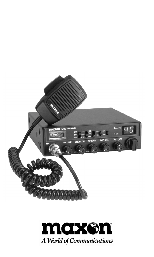
PRODUCT DESCRIPTION
Thank you for choosing the Maxon MCB-100 WXD
Professional 40 Channel Mobile CB / Weather Radio.
Maxon's MCB-100 WXD is designed for either in-dash
or under/over dash installation, easy operation and is
one of the most reliable 40 channel Citizens Band/
weather radios available.
Package Contents:
Main CB unit
Deluxe handheld microphone
CB Unit and microphone mounting hardware
In-dash mounting collar
In-dash faceplate trim ring
In-dash rear support mounting strap
In-dash removal tools
Under /over dash mounting bracket w/mounting
hardware
Owner's manual
Copy of FCC Part 95, Subpart D
NOAA Weather Radio Network frequency
reference card
An external mobile antenna is required for use - antenna
is not included. Refer to Mobile Antenna Information
section for more information.
YOU DO NOT NEED AN FCC LICENSE TO OPERATE
THIS RADIO IN THE UNITED STATES. However, you
must know and be familiar with Part 95 of the FCC Rules
in regard to Subpart D of the Citizens Band Radio Service.
(A copy is enclosed with this unit).
Before operating your Maxon Citizens Band Radio, read this
Owner's Manual carefully. If you have a problem, refer to the
Troubleshooting section of this manual before returning your
radio for repairs.
II

TABLE OF CONTENTS
Specifications
Product Description
Package Contents
FCC Regulations
Performance Features
Controls and Functions
Installation Instructions
In-Dash Installation
Removing the In-Dash CB Unit
Under/Over Dash Installation
DC Power Supply Connection
Negative Ground System Connection
Positive Ground System Connection
Mobile Antenna Information
Antenna Tuning/SWR Meter Operation
Calibrating the SWR Meter
Standing Wave Ratio Chart
Operating Instructions
For CB Operation
To Transmit /To Receive
External Speaker Operation
PA System and Optional PA Speaker Operation
Using the Weather Receiver
Weather Operation
Radio Communication Codes
CB Channel Frequency Chart
Troubleshooting Chart
Warranty Statement
I
II
II
II
1
2
4
4
6
7
9
9
10
11
12
12
14
15
15
16
16
16
17
17
19
20
21
22
III

PERFORMANCE FEATURES
• Multifunctional analog meter measures and displays the
Standing Wave Ratio (SWR) of the CB antenna system;
actual RF output power when transmitting; and input signal
strength when receiving
• 40 CB Channels with 7 NOAA channels for receiving current
local National Weather Service broadcasts and 3 periodic
international marine weather channels
• Maximum legal output power (4 Watts)
• Dual mounting, for in-dash or under / over dash installation
• Direct access to Emergency CH 9 and Highway CH 19
• CB and weather channel selector knobs
• Dual-color LED identifies transmit and receive modes
• Public Address (PA) system circuitry (speaker not included)
• Automatic Noise Limiter (ANL) and noise blanker circuitry
switch reduces atmospheric static noise interference during
CB operation and reduces electrical impulse noise caused by
the vehicle's ignition
• SWR Meter calibration capability
• RF Gain control knob adjusts the receiving sensitivity of
the radio
• Front-mounted, deluxe microphone
• Display bright/dim switch
• Solid state components for years of trouble-free operation
• Highly sensitive, selective dual-conversion superheterodyne
receiver with tuned RF stage
• Last channel memory recalls last channel displayed
• Rugged, metal cabinet
• One year warranty
1

CONTROLS AND FUNCTIONS
A. Microphone Jack
B. Off / On -Volume Control
C. Squelch Control
D. RF Gain Control: Adjusts the receiving sensitivity of the
radio
E. SWR Calibration Control: Manually calibrates the SWR
meter
F. CB/WX Mode Selector: Selects CB or weather operation
G. CB/WX Channel Selector
H. LED Channel display: Indicates the CB channel selected
I. Weather (WX) LED Indicator: Identifies weather mode
J. Receive (RX)/Transmit (TX) LED Indicator: Identifies
radio status
K. Display Bright / Dim Switch
L. CB- PA Switch: Position selects normal CB operation or
Public Address mode
M. NB/ANL-ANL - OFF Switch: Position selects noise blanker
with automatic noise limiter circuitry; ANL circuitry only;
or off
N. CH 9-NOR-CH 19 Switch: Position selects Emergency
CH 9; normal CB channels (1-40); or Highway CH 19
O. S /RF-SWR-CAL Switch: Position selects function of analog
meter: measuring radio input/ output signal power
strength; measuring Standing Wave Ratio of antenna; or
entering SWR calibration mode
P. Front-mounted, Deluxe Microphone
Q. Analog Meter: Measures and displays the Standing Wave
Ratio (SWR) of the CB antenna system; actual RF output
power when transmitting; and input signal strength when
receiving
Antenna Pigtail Jack: Located on back panel, not shown
PA Speaker Jack: Located on back panel, not shown
External Speaker Jack: Located on back panel, not shown
DC Power Cord Jack: Located on back panel, not shown
2
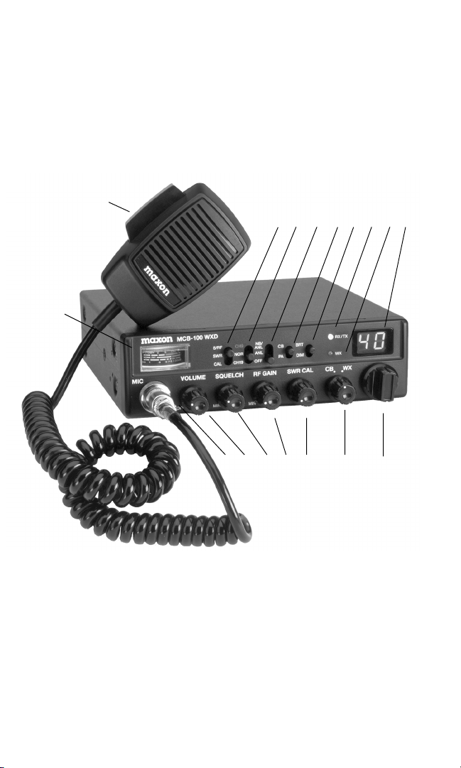
MOBILE CB RADIO
Q
P
O N M L K J I H
A B C D E F G
3

INSTALLATION INSTRUCTIONS
Your new MCB-100 WXD is designed to be installed
in-dash, under/over the dash or anywhere INSIDE your
vehicle. Safety and convenience should be your primary
considerations in deciding exactly where to locate
your CB radio.
CAUTION: Be sure the unit is located where it will
not interfere with the driver or impair access to any
controls necessary for the safe driving of the vehicle.
Before permanently installing the CB radio, connect
the wiring temporarily and make sure it is connected
properly and the CB unit is functioning. (Wiring instructions for power and antenna are located in this manual).
The radio's power and antenna connecting cables must
be routed and secured in such a manner as not to
interfere with the operation of the brake, accelerator
or other controls. Interference from either the CB unit
or its connecting cables may contribute to the loss of
control of the vehicle.
Hardware is provided for in-dash or under/over dash
installations. Use only the parts included with the CB
unit to ensure proper installation. The use of unauthorized parts can cause malfunctions.
In-Dash Installation
In-dash installation requires the following provided
hardware: mounting collar, front faceplate trim ring,
rear metal mounting strap, and microphone hanger
bracket.
4
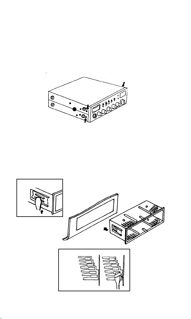
The in-dash CB unit requires a rear support. Use the
provided metal mounting strap (fig. 4) or a rear
support bushing (not included).
DO NOT remove the factory pre-installed screws
from the sides of the radio (fig. 1). They lock the CB
unit securely into the mounting collar.
fig. 1
1. Before inserting the mounting collar into the dash,
push the side tabs inward with a slight pressure
(fig. 2a). Insert the mounting collar into the dash-
board opening (fig. 2b). Select the proper tabs
according to the thickness of the dashboard material
(fig. 3) and bend them up slightly for a secure hold.
fig. 2a
fig. 3
fig. 2b
5
 Loading...