

Page 1

Dual Port, Dual SIM Industrial Cellular Router
User Guide V1. 01
Page 2

!
MULTIMAX(USER(GUIDE(
1!
!
TABLE OF CONTENTS
CONTACT INFORMATION! 3!
TECHNICAL:! 3!
SALES:! 3!
WEBSITE:! 3!
Important Notice! 3!
RF!EXPOSURE!COMPLIANCE! 5!
Caution! 5!
Chapter(1.! Product Concept! 9!
1.1! Overview! 9!
1.2! Packing List! 10!
1.3! Specifications! 12!
1.4! Selection and Ordering Data! 13!
Chapter(2.! Installation! 14!
2.1! LED Indicators! 14!
2.2! Mounting the Router! 15!
2.3! Install the SIM Card and Micro SD Card! 15!
2.4! Connect the External Antenna (SMA Type)! 17!
2.5! PIN assignment for Router! 18!
2.6! Grounding the Router! 19!
2.7! Reset Button! 19!
Chapter(3.! Configuration settings over web browser! 20!
3.1! Configuring PC in Windows! 20!
3.2! Factory Default Settings! 22!
3.3! Control Panel! 23!
3.4! Status -> System! 24!
3.5! Status -> Network! 27!
3.6! Status -> Route! 27!
3.7! Status -> VPN! 28!
3.8! Status -> Event/Log! 29!
3.9! Configuration -> Link Management! 29!
3.10! Configuration -> Cellular WAN! 30!
3.11! Configuration -> Ethernet! 35!
3.12! Configuration -> NAT/DMZ! 36!
3.13! Configuration -> Firewall! 37!
3.14! Configuration -> IP Routing! 39!
3.15! Configuration -> DynDNS! 42!
3.16! Configuration -> IPsec! 44!
3.17! Configuration -> Open VPN! 49!
3.18! Configuration -> L2TP! 54!
Page 3

!
!
!
!
2(
MULTIMAX(USER(GUIDE!
!
3.19! Configuration -> PPTP! 58!
3.20! Configuration -> SNMP! 62!
3.21! Configuration -> Serial! 63!
3.22! Configuration -> VRRP! 69!
3.23! Configuration -> AT over IP! 70!
3.24! Configuration -> Reboot! 70!
3.25! Configuration -> Syslog! 71!
3.26! Configuration -> Phone Book! 71!
3.27! Administration -> Profile! 72!
3.28! Administration -> Tools! 73!
3.29! Administration -> User Management! 75!
3.30! Administration -> Clock! 76!
3.31! Administration -> Update Firmware! 77!
Chapter(4.! Examples of configuration! 78!
4.1! Cellular Dial-Up! 78!
4.2! NAT! 80!
4.3! L2TP! 82!
4.4! PPTP! 84!
4.5! IPSEC VPN! 85!
4.6! OPENVPN! 88!
Chapter 5. Introductions for CLI! 91!
5.1 What’s CLI and hierarchy level Mode! 91!
Page 4

!
MULTIMAX(USER(GUIDE(
3!
!
CONTACT INFORMATION
In keeping with Maxon's dedicated customer support policy, we encourage you to contact us.
TECHNICAL:
Hours of Operation: Monday to Friday 8.30am to 5.30pm*
Telephone: +61 2 8707 3000
Facsimile: +61 2 8707 3001
Email: support@maxon.com.au * Public holidays excluded
SALES:
Hours of Operation: Monday to Friday 8.30am to 5.30pm*
Telephone: +61 2 8707 3000
Facsimile: +61 2 8707 3001
Email: sales@maxon.com.au * Public holidays excluded
WEBSITE: www.maxon.com.au
Maxon has also added for the benefit of developers and integrators, a forum on our website that
can be accessed to discuss this product and/or technical matters in relation to your applications.
All questions raised within this portal will be answered.
Important Notice
Due to the nature of wireless communications, transmission and reception of data can never be
guaranteed. Data may be delayed, corrupted (i.e., have errors) or be totally lost. Although
significant delays or losses of data are rare when wireless devices such as the router are used in a
normal manner with a well-constructed network, the router should not be used in situations where
failure to transmit or receive data could result in damage of any kind to the user or any other party,
including but not limited to personal injury, death, or loss of property. Maxon accepts no
responsibility for damages of any kind resulting from delays or errors in data transmitted or received
using the router, or for failure of the router to transmit or receive such data.
Page 5

!
!
!
!
4(
MULTIMAX(USER(GUIDE!
!
Safety Precautions
General
! The router generates radio frequency (RF) power. When using the router care must be taken
on safety issues related to RF interference as well as regulations of RF equipment.
! Do not use your router in aircraft, hospitals, petrol stations or in places where using GSM
products is prohibited.
! Be sure that the router will not be interfering with nearby equipment. For example: pacemakers
or medical equipment. The antenna of the router should be away from computers, office
equipment, home appliance, etc.
! An external antenna must be connected to the router for proper operation. Only uses
approved antenna with the router. Please contact authorized distributor on finding an
approved antenna.
! Always keep the antenna with minimum safety distance of 26.6 cm or more from human body.
Do not put the antenna inside metallic box, containers, etc.
Note: Some airlines may permit the use of cellular phones while the aircraft is on the ground and
the door is open. Router may be used at this time.
Using the router in vehicle
! Check for any regulation or law authorizing the use of GSM in vehicle in your country before
installing the router.
! The driver or operator of any vehicle should not operate the route while in control of a vehicle.
! Install the router by qualified personnel. Consult your vehicle distributor for any possible
interference of electronic parts by the router.
! The router should be connected to the vehicle’s supply system by using a fuse-protected
terminal in the vehicle’s fuse box.
! Be careful when the router is powered by the vehicle’s main battery. The battery may be
drained after extended period.
Protecting your router
! To ensure error-free usage, please install and operate your router with care. Do remember the
follow:
! Do not expose the router to extreme conditions such as high humidity / rain, high temperatures,
direct sunlight, caustic / harsh chemicals, dust, or water.
! Do not try to disassemble or modify the router. There is no user serviceable part inside and the
warranty would be void.
! Do not drop, hit or shake the router. Do not use the router under extreme vibrating conditions.
! Do not pull the antenna or power supply cable. Attach/detach by holding the connector.
! Connect the router only according to the instruction manual. Failure to do it will void the
warranty.
! In case of problem, please contact authorized distributor.
Page 6

!
MULTIMAX(USER(GUIDE(
5!
!
RF EXPOSURE COMPLIANCE
The use of this device in any other type of host configuration may not comply with the RF exposure
requirements and should be avoided. During operation, a 20 cm separation distance should be
maintained between the antenna, whether extended or retracted, and the user’s/bystander’s
body (excluding hands, wrists, feet, and ankles) to ensure RF exposure compliance.
Caution
Change or modification without the express consent of Maxon Australia Pty. Ltd. voids the user’s
authority to use the equipment. These limits are designed to provide reasonable protection against
harmful interference in an appropriate installation. The modem is a transmitting device with similar
output power to a mobile phone. This equipment generates, uses, and can radiate radio
frequency energy and, if not used in accordance with instructions, can cause harmful radiation to
radio communication. Use only the supplied or an approved antenna. Unauthorized antennas,
modifications, or attachments could impair call quality, damage the device, or result in violation of
RF exposure regulations.
However, there is no guarantee that interference will not occur in a particular installation. If the
equipment does cause harmful interference in radio and television reception, which can be
determined by turning the equipment on and off, the user is encouraged to try to correct the
interference by one or more of the following measures:
" Re-orient or relocate the receiving radio or TV antenna
" Increase the separation distance between the equipment and the receiver
" Contact Maxon Australia Technical Support for assistance.
Notes The user is cautioned that changes or modifications not expressly approved by Maxon
Australia could void the warrantee.
* The product needs to be supplied by a limited power source
or the power supply provided. Otherwise, safety will not be ens
ured
Potentially Unsafe Areas
Posted Facilities: Turn off this device in any facility or area when posted notices require you
to do so.
Blasting Areas: Turn off your device where blasting is in progress. Observe restrictions and
follow any regulations or rules.
Potentially Explosive Atmospheres: Turn off your device when you are in any area with a
Page 7

!
!
!
!
6(
MULTIMAX(USER(GUIDE!
!
potentially explosive atmosphere. Obey all signs and instructions. Sparks in such areas could
cause an explosion or fire, resulting in bodily injury or death.
Areas with a potentially explosive atmosphere are often but not always clearly marked.
They include:
" fuelling areas such as gas or petrol stations
" below deck on boats
" transfer or storage facilities for fuel or chemicals
" vehicles using liquefied petroleum gas, such as propane or butane
" areas when the air contains chemicals or particles such as grain, dust or metal powders
" avoid using the modem in areas that emit electromagnetic waves or enclosed metallic
structures e.g. lifts or any other area where you would normally be advised to turn off
your engine
Page 8

!
MULTIMAX(USER(GUIDE(
7!
!
Regulatory and Type Approval Information
Table 1: Directives
2002/95/
EC
Directive of the European Parliament and of the Council of 27 January 2003
on the restriction of the use of certain hazardous substances in electrical and
electronic equipment (RoHS)
2002/96/
EC
Directive of the European Parliament and of the Council on waste electrical and
electronic equipment (WEEE)
2003/10
8/EC
Directive of the European Parliament and of the Council of 8 December
2003 amending directive 2002/96/ec on waste electrical and electronic
equipment (WEEE)
Table 2: Standards of the Ministry of Information Industry of the People’s Republic of China
SJ/T
11363-2
006
“Requirements for Concentration Limits for Certain Hazardous Substances in
Electronic Information Products” (2006-06).
SJ/T
11364-2
006
“Marking for Control of Pollution Caused by Electronic Information Products”
(2006-06).
According to the “Chinese Administration on the Control of Pollution caused
by Electronic Information Products” (ACPEIP) the EPUP, i.e., Environmental
Protection Use Period, of this product is 20 years as per the symbol shown here, unless
otherwise marked. The EPUP is valid only as long as the product is operated within the
operating limits described in the Hardware Interface Description.
Please see Table 3 for an overview of toxic or hazardous substances or elements that
might be contained in product parts in concentrations above the limits defined by
SJ/T 11363-2006.
Table 3: Toxic or hazardous substances or elements with defined concentration limits
Name of the part
Hazardous substances
(Pb)
(Hg)
(Cd)
(Cr(VI))
(PBB)
(PBDE)
Metal Parts
o o o o o
o
Circuit Modules
x o o o o
o
Cables and Cable
Assemblies
o o o o o
o
Plastic and Polymeric parts
o o o o o
o
o:
Indicates that this toxic or hazardous substance contained in all of the homogeneous materials
for this part is below the limit requirement in SJ/T11363-2006.
x:
Indicates that this toxic or hazardous substance contained in at least one of the homogeneous
materials for this part might exceed the limit requirement in SJ/T11363-2006.
Page 9

!
!
!
!
8(
MULTIMAX(USER(GUIDE!
!
Revision History
Updates between document versions are cumulative. Therefore, the latest document version
contains all updates made to previous versions.
Release
Date
Firmware
Version
Details
2013-01-24
1.00
First Release.
2013-03-15
1.01
Update firmware; Add configuration examples.
Page 10

!
MULTIMAX(USER(GUIDE(
9!
!
Chapter 1. Product Concept
1.1 Overview
The Maxon Multimax MA-2040 is a rugged cellular router offering state-of-the-art mobile
connectivity for machine to machine (M2M) applications.
! Dual SIM redundancy for continuous cellular connection supports 2G/3G/4G.
! Optional diversity antenna for improved fringe performance.
! Two Ethernet ports, can be configured as two LANs or one LAN, one WAN (supports wireless
WAN and wired WAN backup).
! One RS232, one RS485, one console port, two digital inputs, two digital outputs, one high speed
USB host up to 480 Mbps.
! Six LED indicators provide status and signal strength (RSSI).
! Wide range input voltages from 9 to 60 VDC and wide range operating temperature: @25 to
65 °C.
! The metal enclosure can be mounted on a DIN-rail or on the wall, also with extra ground screw.
! Network protocols such as PPP, PPPoE, TCP, UDP, DHCP, ICMP, NAT, DMZ, RIP, OSPF, DDNS,
VRRP, HTTP, HTTPs.
! VPN tunnel: IPSec/OpenVPN/PPTP/L2TP client/server, GRE.
! Management via Web, CLI, SNMP.
! Supports Modbus/RTU to Modbus/TCP gateway.
! Auto reboot during a preset time of a day.
! Firmware upgrade via web interface.
Page 11

!
!
!
!
10(
MULTIMAX(USER(GUIDE!
!
1.2 Packing List
Check your package to make certain it contains the following items:
# Maxon Multimax MA-2040 router x 1
# 3-pin pluggable terminal block with lock for power connector x 1
# 7-pin pluggable terminal block with lock for serial port, I/O and console port x 1
# CD with user guide x 1
Note: Please notify your sales representative if any of the above items are missing or damaged.
Optional accessories (can be purchased separately):
# SMA antenna (Stubby antenna or Magnet antenna optional) x 1
Stubby antenna Magnet antenna
# Ethernet cable x 1
Page 12

!
MULTIMAX(USER(GUIDE(
11!
!
# Wall Mounting Kit
# 35mm Din-Rail mounting kit
# AC/DC Power Supply Adapter (12VDC, 1.5A) x 1 (EU, US, UK, AU plug optional)
Page 13

!
!
!
!
12(
MULTIMAX(USER(GUIDE!
!
1.3 Specifications
Cellular Interface
! Standards: GSM/GPRS/EDGE/UMTS/HSPA/FDD LTE
! GPRS/EDGE: 850/900/1800/1900 MHz
! HSUPA: 900/2100 or 850/1900 MHz optional, DL/UL 7.2/5.76 Mbps, fallback to 2G
! HSPA+: 850/900/1900/2100 or 900/2100 or 850/1900 MHz optional, DL/UL 14.4/5.76 Mbps,
fallback to 2G
! FDD LTE: 800/900/1800/2100/2600 MHz or 700 MHz (B17 or B13) optional, DL/UL 100/50 Mbps,
fallback to 3G/2G
! SIM: 2 x (3V & 1.8V)
! Antenna Interface: SMA Female, 50 ohms impedance
Ethernet Interface
! Number of Ports: 2 x 10/100 Mbps, 2 LANs or 1 LAN 1 WAN
! Magnet Isolation Protection: 1.5KV
Serial Interface
! Number of Ports: 1 x RS-232, 1 x RS-485
! ESD Protection: 15KV
! Parameters: 8E1, 8O1, 8N1, 8N2, 7E2, 7O2, 7N2, 7E1
! Baud Rate: 2000bps to 115200bps
! Flow Control: RTS/CTS, XON/XOFF
! RS-232: TxD, RxD, RTS, CTS, GND
! RS-485: Data+ (A), Data- (B), GND
! Interface: 3.5mm terminal block with lock
Digital Input
! Type: 2 x DI, Dry Contact
! Dry Contact: On: short to GND, Off: open
! Isolation: 3K VDC or 2K Vrms
! Digital Filtering Time Interval: Software selectable
! Over-voltage Protection: 36 VDC
! Interface: 3.5mm terminal block with lock
Digital Output
! Type: 2 x DO, Sink
! Over-voltage Protection: 40 VDC
! Over-current Protection: 0.5 A
! Isolation: 3K VDC or 2K Vrms
! Interface: 3.5mm terminal block with lock
Page 14

!
MULTIMAX(USER(GUIDE(
13!
!
System
! LED Indicators: 6 indicators, RUN, PPP, USR, RSSI, NET, SIM
! Built-in RTC, Watchdog, Timer
! Expansion: 1 x USB 2.0 host up to 480 Mbps
! Storage: 1 x MicroSD, can expand up to 2G
Software
! Network protocols: PPP, PPPoE, TCP, UDP, DHCP, ICMP, NAT, DMZ, RIP v1/v2, OSPF, DDNS, VRRP,
HTTP, HTTPs, DNS, ARP, SSH, SNTP, Telnet
! LinkGo: PPP LCP Echo/Reply, ICMP to keep always online
! VPN tunnel: IPSec/OpenVPN/PPTP/L2TP, GRE
! Firewall: SPI, anti-DoS, Filter, Access Control
! Management: Web, CLI, Telnet, SNMP v1/v2/v3
! Serial Port: TCP client/server, UDP, Virtual COM
Power Supply and Consumption
! Power Supply Interface: 5mm terminal block with lock
! Input Voltage: 9 to 60 VDC
! Power Consumption: Idle: 100 mA @ 12 V
Data Link: 500 to 1000 mA (peak) @ 12 V
Physical Characteristics
! Housing & Weight: Metal, 500g
! Dimension: (L x W x H): 125 x 108 x 45 mm
! Installation: 35mm Din-Rail or wall mounting or desktop
Environmental Limits
! Operating Temperature & Humidity: -25 to 65°C, 5 to 95% RH
! Storage Temperature: -40 to 85°C
Regulatory and Type Approvals
! Approval & Detective: CE, FCC, PTCRB, A-Tick, RoHS, WEEE
! EMC: EN 61000-4-2 (ESD) Level 4, EN 61000-4-3 (RS) Level 4
EN 61000-4-4 (EFT) Level 4, EN 61000-4-5 (Surge) Level 3
EN 61000-4-6 (CS) Level 3, EN 61000-4-8, EN 61000-4-12
1.4 Selection and Ordering Data
Please refer to corresponding MA-2040 datasheet.
Page 15
!
!
!
!
14(
MULTIMAX(USER(GUIDE!
!
Chapter 2. Installation
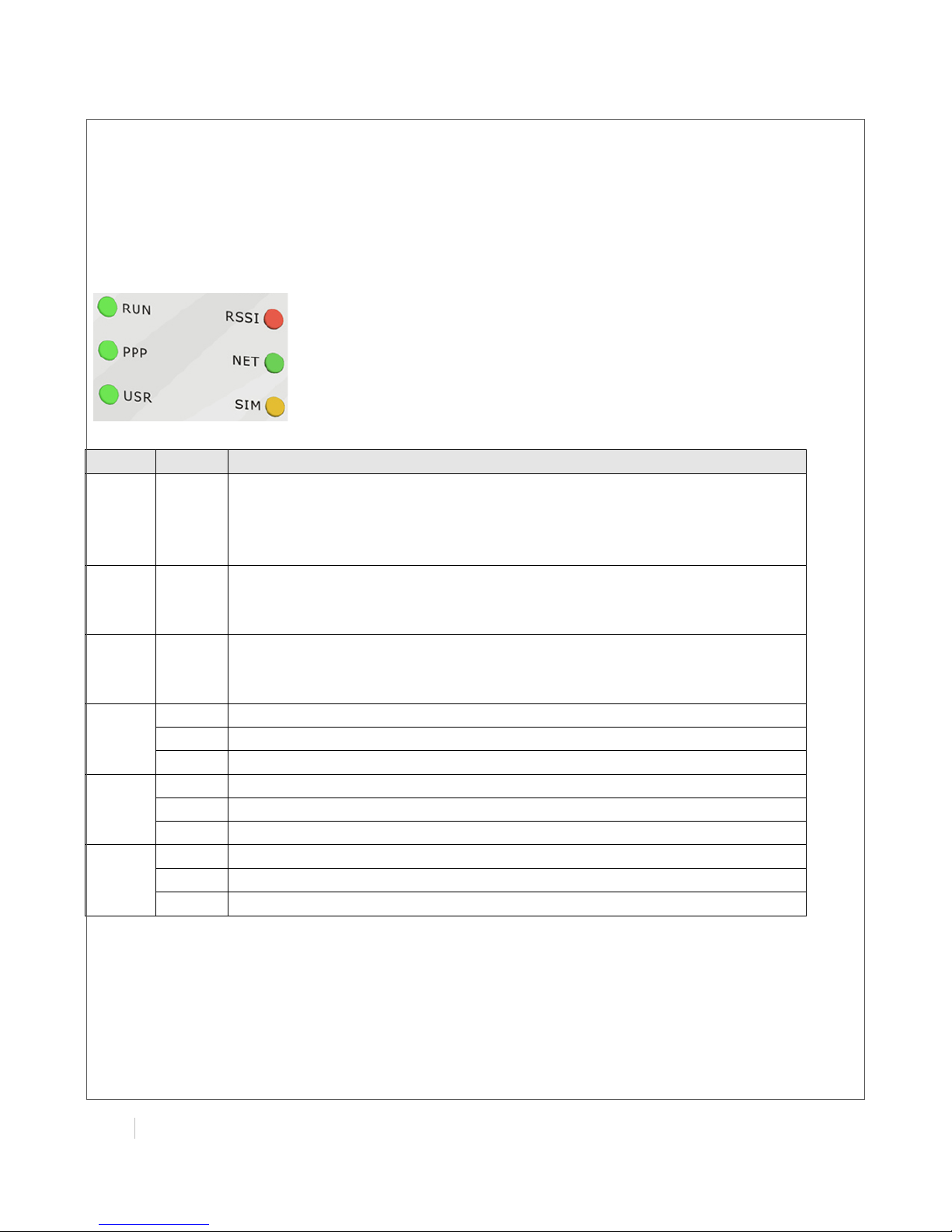
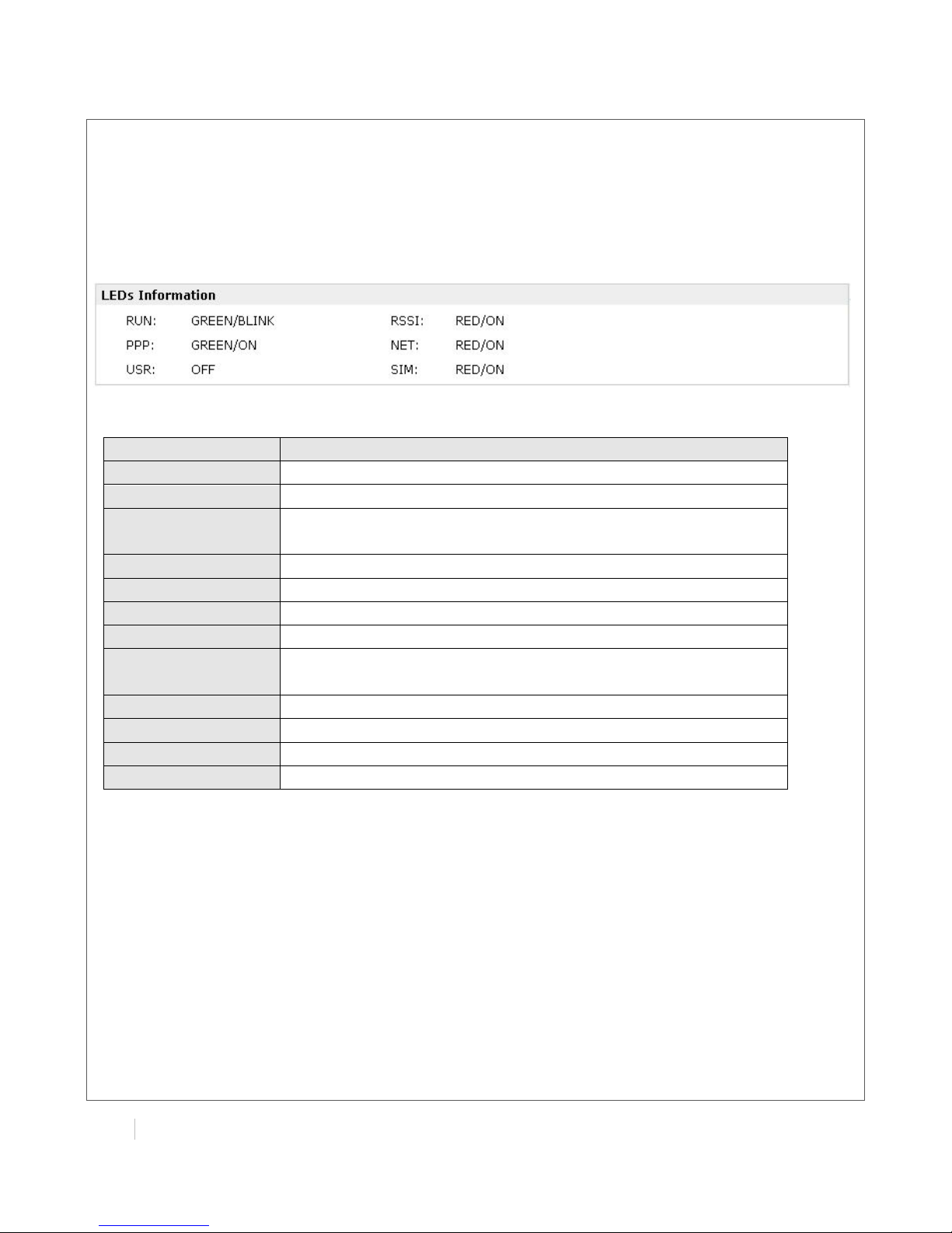
2.1 LED Indicators
Name
Color
Function
RUN
Green
Indicating the system status.
Blinking: Router is ready.
On: Router is starting.
Off: Router is power of.
PPP
Green
Indicating the PPP connection status.
On: PPP connection is established.
Off: PPP connection is failed.
USR
Green
Indicating the VPN status.
On: VPN tunnel is established.
Off: No VPN tunnel.
RSSI
Green
Signal level: 21-31 (Perfect signal level)
Yellow
Signal level: 11-20 (Normal signal level)
Red
Signal level: 1-10 (Bad signal level)
NET
Green
Working under 4G network.
Yellow
Working under 3G network.
Red
Working under 2G network.
SIM
Green
2 SIM cards inserted.
Yellow
Only SIM 2 inserted.
Red
Only SIM 1 inserted.
Page 16
!
MULTIMAX(USER(GUIDE(
15!
!
2.2 Mounting the Router
Use 2 pcs of M3 screw to mount the router on the wall.
Or to mount the router on a DIN rail, you need three pcs of M3 screws.
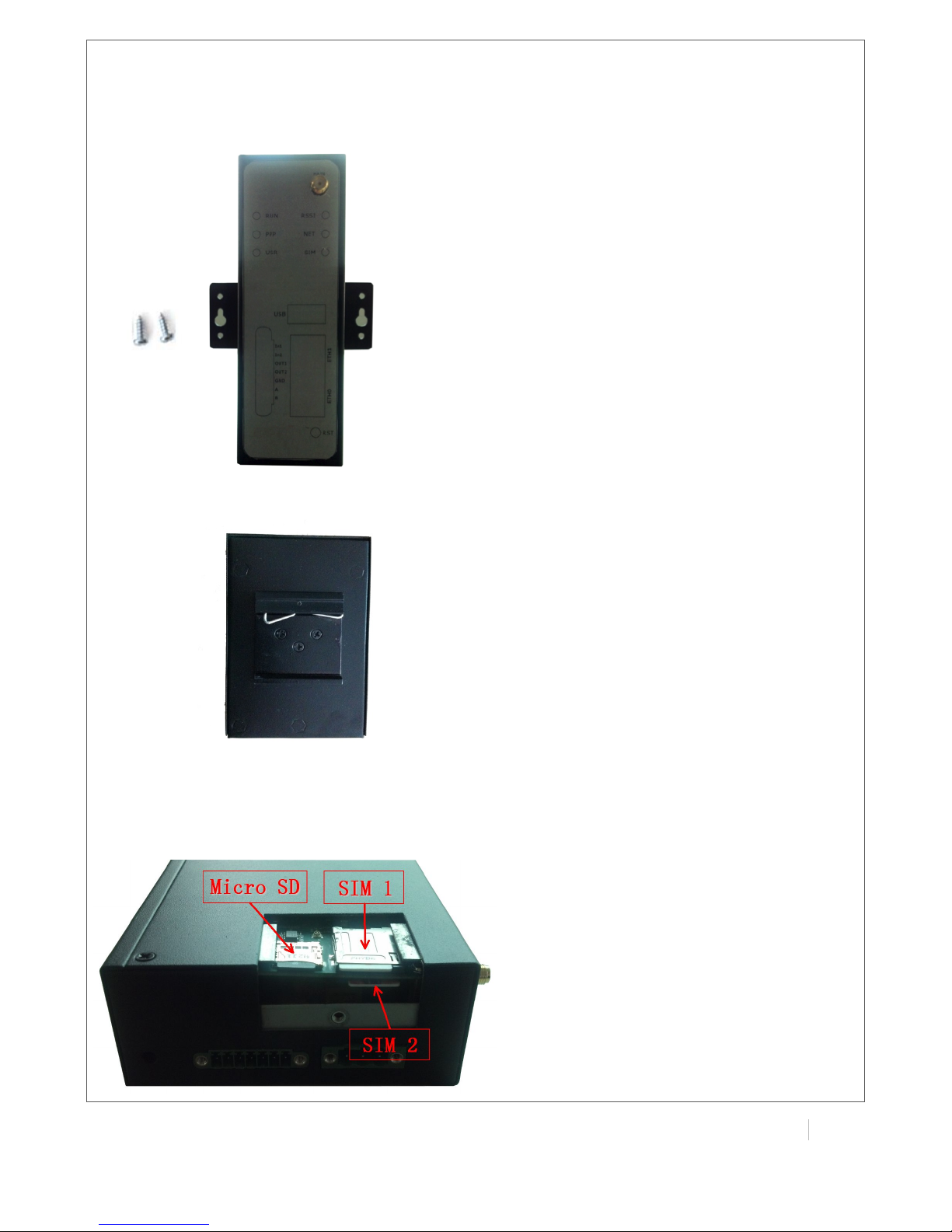
2.3 Install the SIM Card and Micro SD Card
Page 17

!
!
!
!
16(
MULTIMAX(USER(GUIDE!
!
! Inserting SIM Card or Micro SD Card
1. Make sure power supply is disconnected.
2. Use a screwdriver to unscrew the screw on the cover, and then remove the cover, you could
find the SIM Card slots and the Micro SD slot.
3. Insert the SIM card or Micro SD card, and you need press the card with your fingers until you
hear “a cracking sound”. Then use a screwdriver to screw the cover.
! Removing SIM Card or Micro SD Card
1. Make sure your charger is disconnected, and then press and hold down the power key until
the router is powered off.
2. Press the card until you hear “a cracking sound”, when the card will pop up to be pulled out.
Note:
1. Don’t forget screw the cover for again-theft.
2. Don’t touch the metal surface of the SIM card in case information in the card is lost or
destroyed.
3. Don’t bend or scratch your SIM card. Keep the card away from electricity and magnetism.
4. Make sure to disconnect the power source from your router before inserting and removing your
SIM card or Micro SD card.
Page 18
!
MULTIMAX(USER(GUIDE(
17!
!
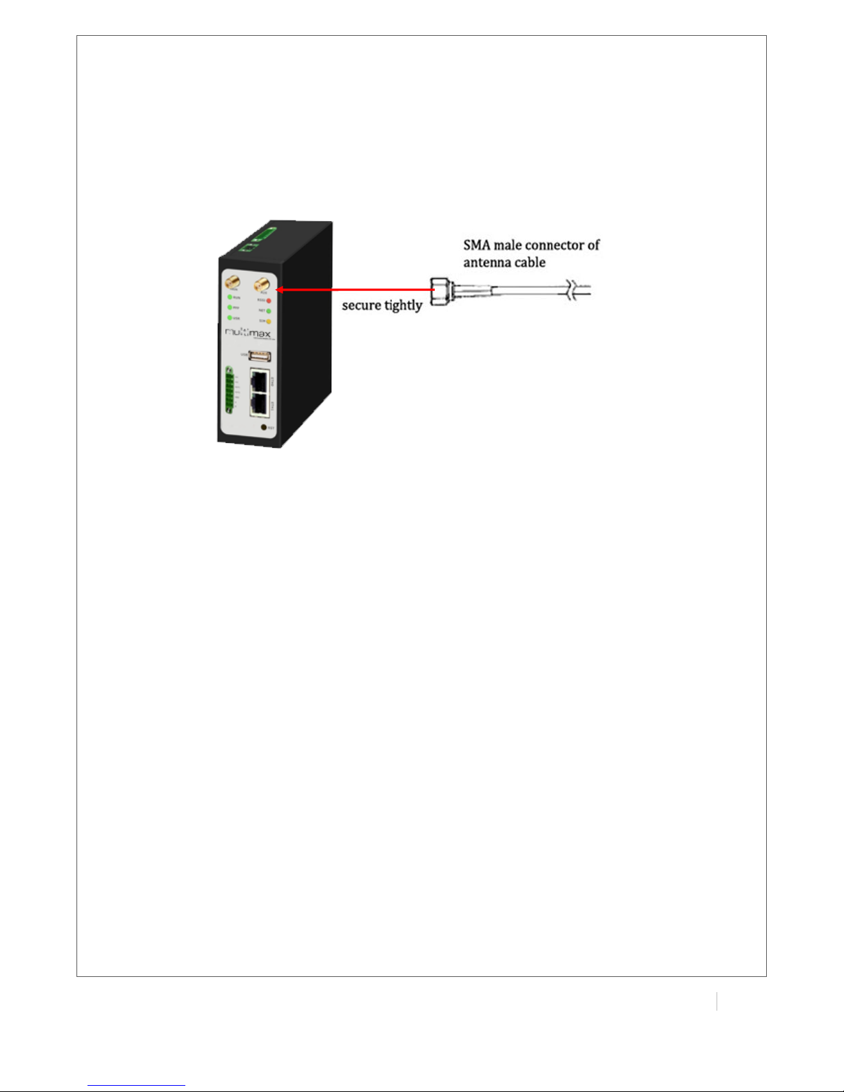
2.4 Connect the External Antenna (SMA Type)
Connect this to an external antenna with SMA male connector. Make sure the antenna is for the
correct frequency as your GSM/3G/4G operator with impedance of 50ohm, and also connector is
secured tightly.
Page 19
!
!
!
!
18(
MULTIMAX(USER(GUIDE!
!
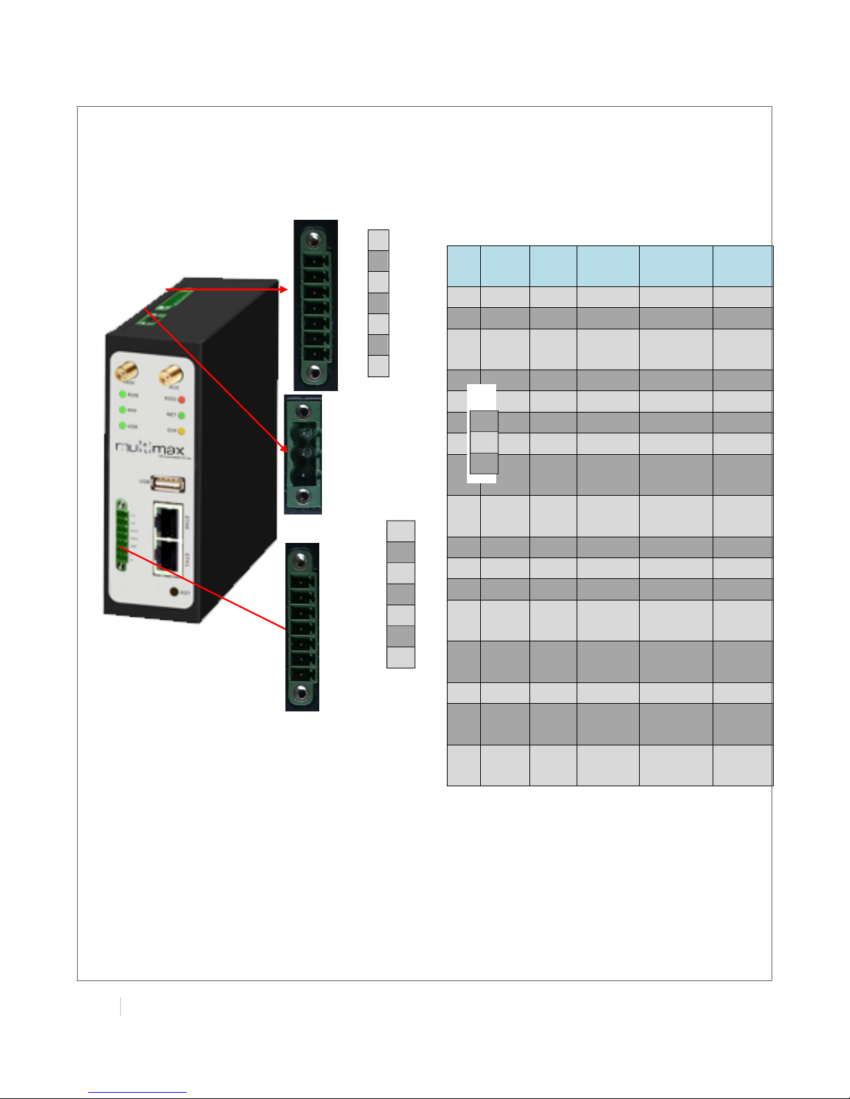
2.5 PIN assignment for Router
Note: The power supply range is 12 to 70VDC.
Please take care about the polarity, and do not
make reverse connection.
1 2 3 4 5 6 7 PIN
Deb
ug
RS23
2
Power
Digital
I/O
RS485
1
RXD
2
TXD
3
GND
GND
4 TXD
5
RXD
6
RTX 7 CTX
8
Positiv
e
9
Negati
ve
10
GND
11 Input 1
12 Input 2
13 Output
1
14 Output
2 15 GND
16
Data+
(A)
17
Data(B)
!
8!9!10!!11!
12!
13!
14!
15!
16!
17!
Page 20
!
MULTIMAX(USER(GUIDE(
19!
!
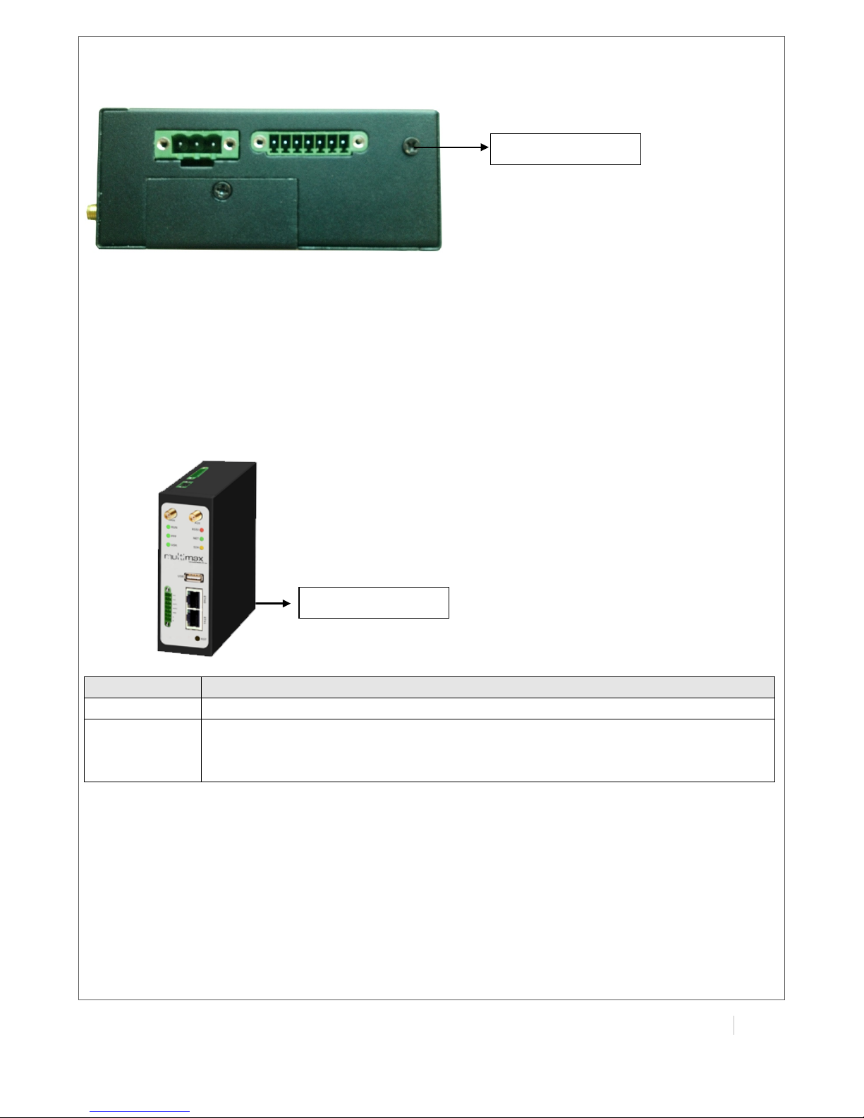
2.6 Grounding the Router
Grounding and wire routing help limit the effects of noise due to electromagnetic interference
(EMI). Run the ground connection from the ground screw to the grounding surface prior to
connecting devices.
Note: This product is intended to be mounted to a well-grounded mounting surface, such as a
metal panel.
2.7 Reset Button
Function
Operation
Reboot
Push the button for 5 seconds under working status.
Restore to
factory
default setting
Push the button for 60 seconds once you power on the router until all the three
LEDs at the left side (RUN, PPP, USR) blink at the same time for 5 times.
Grounding(Screw(
Reset(Button(
Page 21
!
!
!
!
20(
MULTIMAX(USER(GUIDE!
!
Chapter 3. Configuration settings over web
browser
The router can be configured through your web browser. A web browser is included as a standard
application in the following operating systems: Linux, Mac OS, Windows 98 /NT /2000 /XP /Me /Vista
/7 /8, etc. The product provides an easy and user-friendly interface for configuration.
There are various ways to connect the router, either through an external repeater/hub or connect
directly to your PC. However, make sure that your PC has an Ethernet interface properly installed
prior to connecting the router.
You must configure your PC to obtain an IP address through a DHCP server or a fixed IP address
that must be in the same subnet as the router. The best and easiest way is to configure the PC to
get an IP address automatically from the router using DHCP. If you encounter any problems
accessing the router web interface it is advisable to uninstall your firewall program on your PC, as
these tend to cause problems accessing the IP address of the router.
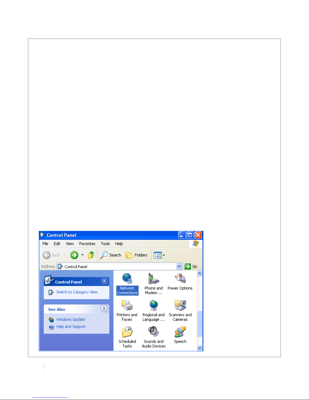
3.1 Configuring PC in Windows
1. Go to Start / Control Panel (in Classic View). In the Control Panel, double-click Network
Connections.
2. Double-click Local Area Connection.
Page 22
!
MULTIMAX(USER(GUIDE(
21!
!
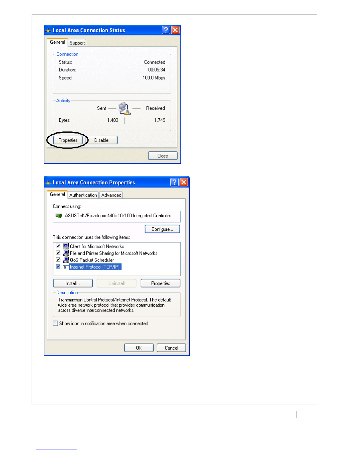
3. In the LAN Area Connection Status window, click Properties.
4. Select Internet Protocol (TCP/IP) and click Properties.
Page 23
!
!
!
!
22(
MULTIMAX(USER(GUIDE!
!
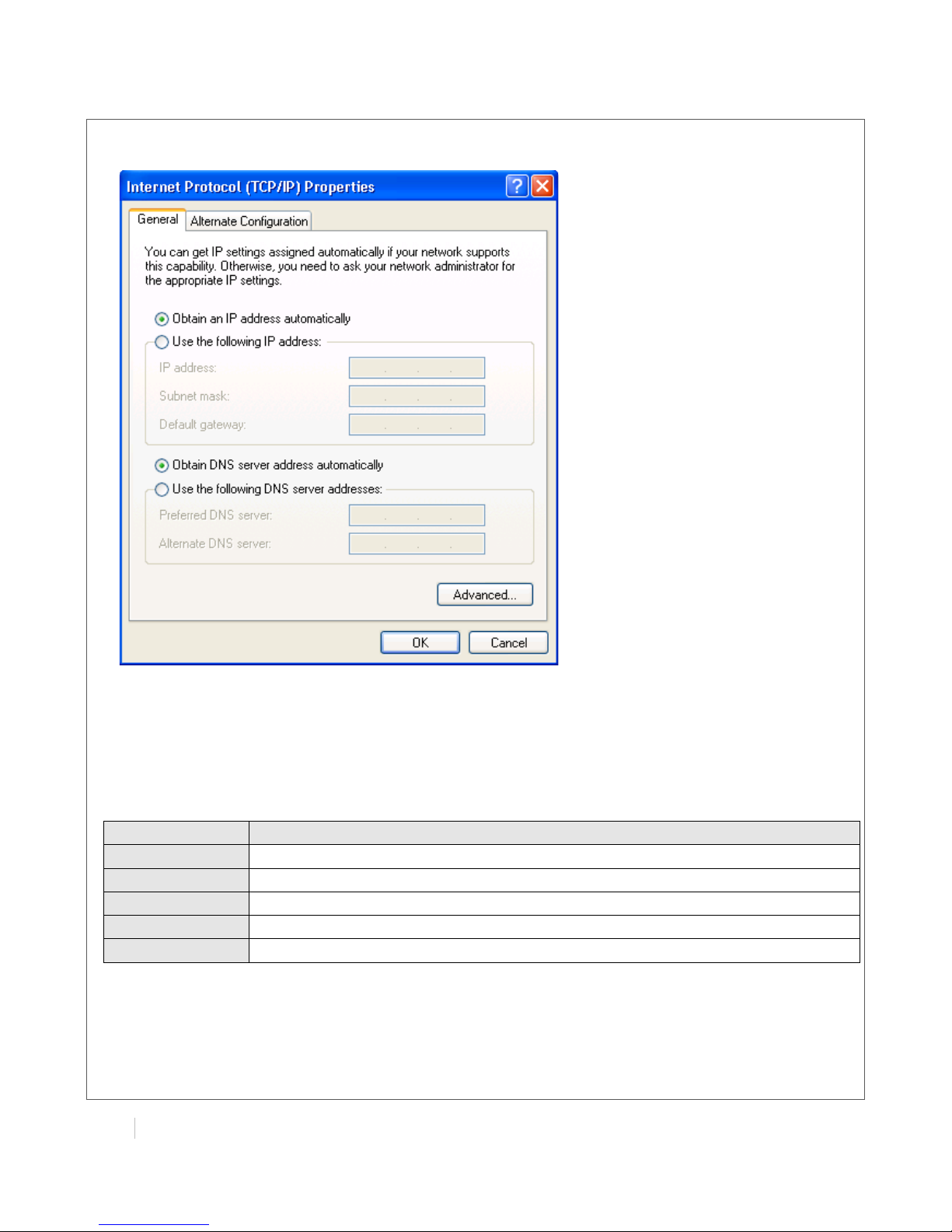
5. Select the Obtain an IP address automatically and Obtain DNS server address automatically
radio buttons.
6. Click OK to finish the configuration.
3.2 Factory Default Settings
Before configuring your router, you need to know the following default settings.
Item
Description
Username
admin
Password
admin
Eth0
192.168.0.1/255.255.255.0, LAN mode
Eth1
192.168.0.1/255.255.255.0, LAN mode
DHCP Server
Enabled.
Page 24
!
MULTIMAX(USER(GUIDE(
23!
!
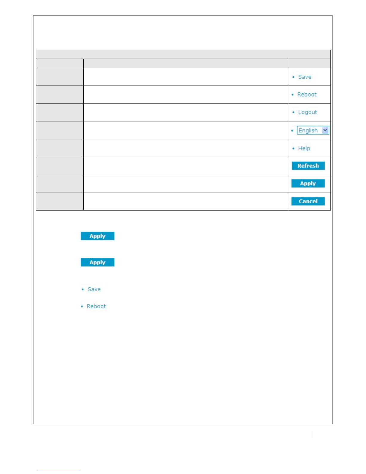
3.3 Control Panel
This section allows users to save configuration, reboot router, logout and select language.
Control Panel
Item
Description
Button
Save
Click to save the current configuration into router’s flash.
Reboot
After save the current configuration, router needs to be rebooted
to make the modification taking effect.
Logout
Click to return to the login page.
Language
Select from English and Chinese.
Help
Click to get some help from our website.
Refresh
Click to refresh the status.
Apply
Click to apply the modification on every configuration page.
Cancel
Click to cancel the modification on every configuration page.
Note: The steps of how to modify configuration are as bellow:
1. Modify in one page;
2. Click under this page;
3. Modify in another page;
4. Click under this page;
5. Complete all modification;
6. Click ;
7. Click .
Page 25
!
!
!
!
24(
MULTIMAX(USER(GUIDE!
!
3.4 Status -> System
This section displays the router’s system status, which shows you a number of helpful information
such as the LEDs information, Router information, Current WAN Link and Cellular Information.
LEDs Information
For the detail description, please refer to 2.2 LED Indicators.
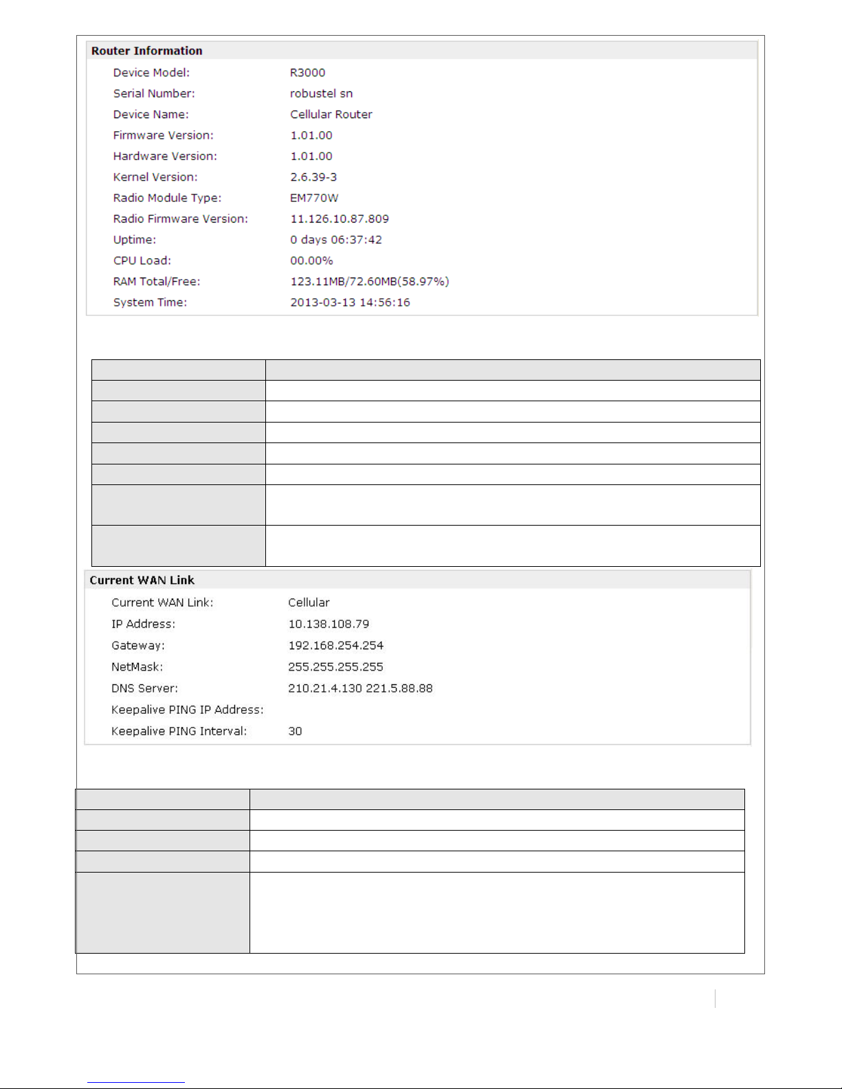
Router Information
Item
Description
Device Model
Show the model name of this device
Serial Number
Show the serial number of this device
Device Name
Show the device name to distinguish different devices you
have installed.
Firmware Version
Show the current firmware version
Hardware Version
Show the current hardware version
Kernel Version
Show the current kernel version
Radio Module Type
Show the current radio module type
Radio Firmware
Version
Show the current radio firmware version
Uptime
Show how long the router have been working since power on
CPU Load
Show the current CPU load
RAM Total/Free
Show the total capacity /Free capacity of RAM
System Time
Show the current system time
Page 26
!
MULTIMAX(USER(GUIDE(
25!
!
Current WAN Link
Item
Description
Current WAN Link
Show the current WAN link: Cellular or Eth
IP Address
Show the current WAN IP address
Gateway
Show the current gateway
Netmask
Show the current netmask
DNS Server
Show the current primary DNS server and Secondary server
Keeping PING IP
Address
Show the current ICMP detection server which you can set in
“Configuration->Link Management”.
Keeping PING Interval
Show the ICMP Detection Interval (s) which you can set in
“Configuration->Link Management”.
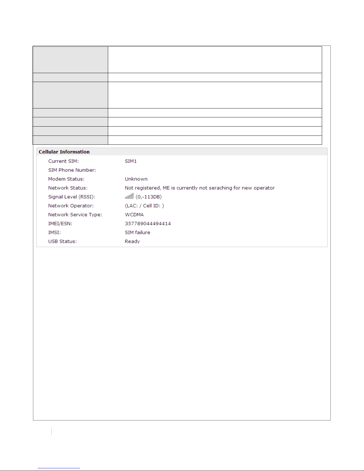
Cellular Information
Item
Description
Current SIM
Show the SIM card which the router work with currently: SIM1 or SIM2
SIM Phone Number
Show the phone number of the current SIM
Modem Status
Network Status
Show the current network state. There are 5 different states:
1. Not registered, ME is currently not searching for new operator!
2. Registered to home network.
3. Not registered, but ME is currently searching for a new operator.
Page 27
!
!
!
!
26(
MULTIMAX(USER(GUIDE!
!
4. Registration denied.
5. Registered, roaming.
6. Unknown.
Signal Level (RSSI)
Show the current signal level
Network Operator
Show Mobile Country Code (MCC) +Mobile Network Code (MNC),
e.g. 46001.
Also it will show the Location Area Code (LAC ) and Cell ID
Network Service Type
Show the current network service type, e.g. GPRS.
IMEI/ESN
Show the IMEI/ESN number of the radio module
IMSI
Show the IMSI number of the current SIM
USB Status
Show the current status of USB host
Page 28
!
MULTIMAX(USER(GUIDE(
27!
!
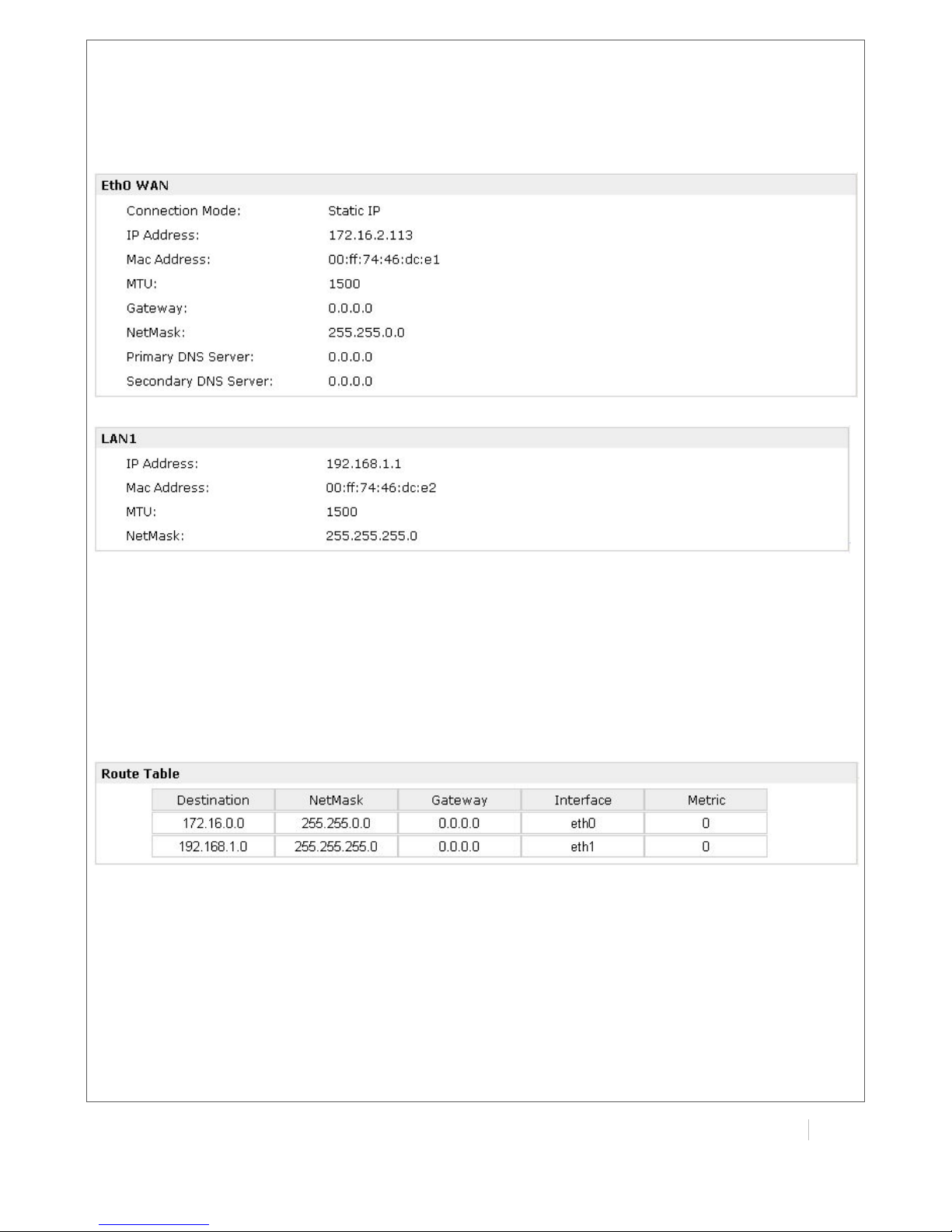
3.5 Status -> Network
This section displays the router’s Network status, which include status of Eth0 WAN and LAN1
Note: ETH0 WAN information will not be shown if you select “Cellular Only” in “Configuration”->”Link
Management”->”WAN Link”.
3.6 Status -> Route
This section displays the router’s route table.
Page 29
!
!
!
!
28(
MULTIMAX(USER(GUIDE!
!
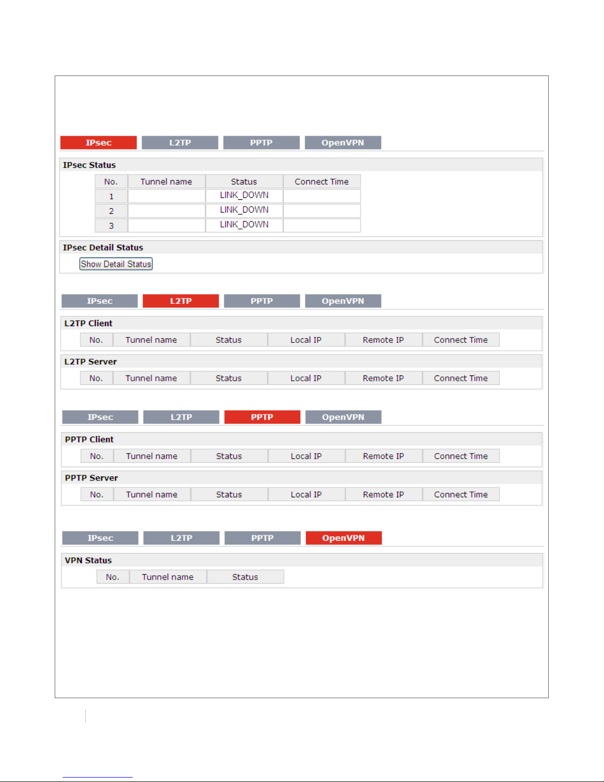
3.7 Status -> VPN
This section displays the router’s VPN status, which include IPsec, L2TP, PPTP and OpenVPN.
Page 30
!
MULTIMAX(USER(GUIDE(
29!
!
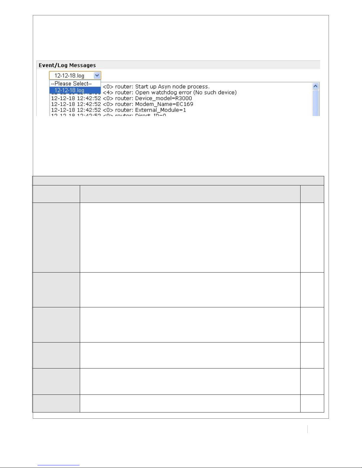
3.8 Status -> Event/Log
This section displays the router’s event/log information. You need to enable router to output the log
and select the log level first, then you can view the log information here.
3.9 Configuration -> Link Management
This section allows users to set the WAN link and the related parameters.
Link Management
Item
Description
Defa
ult
WAN Link
Selected from “Cellular Only”, “Eth0 Only”, “Eth0 as primary and if fail use
cellular” and “Cellular as primary and if fail use Eth0”.
Cellular Only: Select to make cellular as the only WAN link.
Eth0 Only: Select to make Eth0 as the only WAN link
Eth0 as primary and if fail use cellular: Select to make Eth0 as the primary
WAN link and cellular as the secondary WAN link.
Cellular as primary and if fail use Eth0: Select to make cellular as the
primary WAN link and Eth0 as the secondary WAN link.
Cellul
ar
Only
ICMP
Detection
Primary
Server
Router will ping this primary address/domain name to check that if the
current connectivity is active.
Null
ICMP
Detection
Secondary
Server
Router will ping this secondary address/domain name to check that if
the current connectivity is active.
Null
ICMP
Detection
Interval
Set the ping interval time.
Null
ICMP
Detection
Timeout
Set the ping timeout.
30
ICMP
Detection
If Router ping the preset address/domain name time out continuously for
Max Retries time, it will consider that the connection has been lost.
3
Page 31

!
!
!
!
30(
MULTIMAX(USER(GUIDE!
!
Retries
Reset The
Interface
Enable to reset the cellular/ETH0 interface after the max ICMP detection
retries.
3
3.10 Configuration -> Cellular WAN
This section allows users to set the Cellular WAN and the related parameters.
Note: This section will not be displayed if you select “Eth0 Only” in “Configuration”->”Link
Management”->”WAN Link”.
Basic
Cellular WAN @ Basic
Item
Description
Default
Network
Provider Type
Select from “Auto”, “Custom” or the ISP name you preset in
“Configuration”->”Cellular WAN”->”ISP Profile”.
Auto: Router will get the ISP information from SIM card, and set the
APN, username and password automatically. This option only works
when the SIM card is from well-known ISP.
Custom: Users need to set the APN, username and password
manually.
Auto
APN
Access Point Name for cellular dial-up connection, provided by local
ISP.
Null
Username
User Name for cellular dial-up connection, provided by local ISP.
Null
Password
Password for cellular dial-up connection, provided by local ISP.
Null
Dialup No.
Dialup number for cellular dial-up connection, provided by local ISP.
*99***1#
PIN code
request
After click this button, you could input your SIM’s PIN and store the
current PIN in its memory, and then enter the PIN automatically each
time the system boots up.
Note: Please ask your local GSM ISP to see whether your SIM card
Null
Page 32

!
MULTIMAX(USER(GUIDE(
31!
!
requiring PIN or not.
If you want to change the SIM PIN, please click the button to enable
it, and then input the new PIN.
Connection
Mode
Select from “Always Online” and “Connect On Demand”.
Always Online: Router will automatically to establish a GPRS/3G
connection after power on and each restarts, this will remain and will
be re-established after an interruption.
Connect On Demand: After selection this option, user could
configure Triggered by Serial Data, Triggered by Periodically
Connect and Triggered by Time Schedule.
Note: If you select several connect on demand polices, router only
have to meet one of them to be triggered.
Connect
On
Demand
Redial
Interval
Router will automatically re-connect with this interval when it fails
communicating to peer via TCP or UDP
30
Max Retries
The maximum retries times for automatically re-connect when router
fails to dial up.
After maximum retries, router will reboot the wireless module. If router
still cannot dial up successfully, it will try to switch to the other SIM
card. Then router will re-connect with the other SIM card with
maximum retries.
When connecting successful, the Max Retries counter will be set to 0.
3
Inactivity
Time
You can configure this field after setting router under “Connect On
Demand” mode.
This field specifies the idle time setting for GPRS/3G
auto-disconnection and trying to revert back to preferred SIM card.
0 means timeless.
0
Serial Output
Content
The content which output to the serial device which connect to
router and inform it that router is ready to receive serial data.
Null
Triggered by
Serial Data
Tick this checkbox to allow router automatic connects to cellular
network from idle mode when there is data come out from serial
port.
Enable
Periodically
Connect
Tick this checkbox to allow router automatically connects to cellular
network with preset interval which you preset in Periodically Connect
Interval.
Enable
Periodically
Connect
Interval
Periodically Connect Interval for Periodically Connect.
300
Time
Schedule
Select the Time Range to allow router automatically connects to
cellular network during this time range.
NULL
Time Range
Adding the Time Range for Time Schedule. You can set the days of
one week and at most three ranges of time of one day.
Null
Main SIM
Card
Set the preferred SIM card from SIM 1 or SIM 2.
SIM1
When
Connection
If router cannot dialup or ping the preset address timeout
continuously for Max Retries time, it will switch to the other SIM card.
Enable
Page 33

!
!
!
!
32(
MULTIMAX(USER(GUIDE!
!
Fails
When
Roaming is
Detected
Router will switch to backup SIM card when preferred SIM card is
roaming.
Disable
Preferred
PLMN
The identifier for Router to check if it is in home location area or in
roaming area, and decide if it needs to switch back to preferred SIM
card.
Null
Monthly Data
Traffic
Limitation
If the SIM card that the router worked with currently has reached the
data traffic limitation you preset, it will switch to the other SIM card.
Disable
Max Data
limitation
Set the monthly data traffic limitation.
100
Date of
Month to
Clean
Set one day of month to restore the used data to 0.
1
Note: This section will not be displayed if you select “Eth0 Only” in “Configuration”->”Link
Management”->”WAN Link”.
Page 34

!
MULTIMAX(USER(GUIDE(
33!
!
Advanced
Cellular WAN @Advanced
Item
Description
Default
SIM Phone
Number
Set the SIM card’s phone number, and it will be showed in
“Status”->”System”->”System”->”Cellular WAN Information”-“SIM
Phone Number”.
In general, you don’t need to set this number because router will read
it from the SIM card automatically.
Null
Network Type
Select from “auto” or the specific network type which the wireless
module supports.
auto
Band Mode
Select from “ALL” or the specific band which the wireless module
supports.
ALL
Authenticatio
n
Select from “Auto”, “PAP” and “CHAP” as the local ISP required.
Auto
MTU
Maximum Transmission Unit. It is the identifier of the maximum size of
packet, which is possible to transfer in a given environment.
GSM900
MRU
Maximum Receiving Unit. It is the identifier of the maximum size of
packet, which is possible to receive in a given environment.
Auto
Asyncmap
One of the PPP initialization strings. In general, you don’t need to
1
Page 35

!
!
!
!
34(
MULTIMAX(USER(GUIDE!
!
Value
modify this value.
Use Peer DNS
Enable to obtain the DNS server’s address from the ISP.
Enable
Primary DNS
Server
Set the primary DNS server’s address. This item will be unavailable if
you enable “Use Peer DNS”.
Null
Secondary
DNS Server
Set the secondary DNS server’s address. This item will be unavailable if
you enable “Use Peer DNS”.
Null
Address/Cont
rol
Compression
Used for PPP initialization. In general, you need to enable it as default.
Enable
Protocol Field
Compression
Used for PPP initialization. In general, you need to enable it as default.
Enable
Expert
Options
You can enter some other PPP initialization strings in this field. Each
string can be separated by a space.
noccp
nobsdco
mp
ISP Profile
This section allow users to preset some ISP profiles which will be shown in the selection list of
“Configuration”->”Cellular WAN”->”Network Provider Type”.
Cellular WAN @ Basic
Item
Description
Defaul
t
ISP
Input the ISP’s name which will be shown in the selection list of
“Configuration”->”Cellular WAN”->”Network Provider Type”.
Null
APN,
Username,
All these parameters were provided by the ISP.
Null
Page 36

!
MULTIMAX(USER(GUIDE(
35!
!
Password,
Dialup No.
3.11 Configuration -> Ethernet
This section allows users to set the Ethernet WAN and LAN parameters.
Eth0/Eth1
Ethernet @ Eth0
Item
Description
Default
Ethernet
Interface Type
Eth0 can work under two different kinds of mode: LAN and WAN.
LAN
Enable Bridge
@ LAN Interface
Enable to make Eth0 works under bridge mode with Eth1. Eth0 and
Eth1 will have the same IP address under this mode.
Enable
IP Address,
NetMask, MTU
@ LAN Interface
Set the IP address, netmask and MTU of Eth0/Eth1. These
parameters will be unconfigurable if you enable Bridge.
Null
Multiple IP
Address @ LAN
Interface
Assign multiple IP addresses for Eth0/Eth1.
Null
Enable DHCP
Server @ DHCP
Server
Enable to make router can lease IP address to DHCP clients which
connect to Eth0/Eth1.
Enable
IP Pool Start, IP
Pool End @
DHCP Server
Define the beginning (IP Pool Start) and end (IP Pool End) of the
pool of IP addresses which will lease to DHCP clients.
192.168.0.2
/
192.168.0.1
00
Netmask @
DHCP Server
Define the netmask which the DHCP clients will obtain from DHCP
server.
255.255.25
5.0
Lease Time @
DHCP Server
Define the time which the client can use the IP address which
obtained from DHCP server.
60
Primary/Second
ary DNS Server
@ DHCP Server
Define the primary/secondary DNS Server which the DHCP clients
will obtain from DHCP server.
192.168.0.1
/
0.0.0.0
WINS Server @
DHCP Server
Define the WINS Server which the DHCP clients will obtain from
DHCP server.
192.168.0.1
Static Lease @
DHCP Server
Define to lease static IP Addresses, which conform to MAC
Address of the connected equipment.
Null
Page 37

!
!
!
!
36(
MULTIMAX(USER(GUIDE!
!
3.12 Configuration -> NAT/DMZ
This section allows users to set the NAT/DMZ parameters.
Port Forwarding
Port Forwarding @ NAT/DMZ
Item
Description
Defa
ult
Port
Forwarding
Manually defining a rule in the router to send all data received on some
range of ports on the internet side to a port and IP address on the LAN
side.
Null
Remote IP
Set the remote IP address.
Null
Page 38

!
MULTIMAX(USER(GUIDE(
37!
!
Arrives At
Port
The port of the internet side which you want to forward to LAN side.
Null
Is Forwarded
to IP Address
The device’s IP on the LAN side which you want to forward the data to.
Null
Is Forwarded
to Port
The device’s port on the LAN side which you want to forward the data
to.
Null
Protocol
Select from “TCP”, “UDP” or “TCP&UDP” which depends on the
application.
TCP
DMZ
DMZ @ NAT/DMZ
Item
Description
Defaul
t
DMZ
DMZ host is a host on the internal network that has all ports exposed,
except those ports otherwise forwarded.
Null
Enable DMZ
Select to enable the DMZ function.
Enabl
e
DMZ Host
Enter the IP address of the DMZ host which on the internal network.
0.0.0.0
Source
Address
Set the address which can talk to the DMZ host. Null means for any
addresses.
0.0.0.0
3.13 Configuration -> Firewall
This section allows users to set the firewall parameters.
Filter Basic Settings
Filter Basic Settings @ Firewall
Item
Description
Defaul
t
Remote
Enable to allow users to access the router remotely on the internet
Enable
Page 39

!
!
!
!
38(
MULTIMAX(USER(GUIDE!
!
Access Using
HTTP
side via HTTP.
Remote
Access Using
TELNET
Enable to allow users to access the router remotely on the internet
side via Telnet.
Enable
Remote
Access Using
SNMP
Enable to allow users to access the router remotely on the internet
side via SNMP.
Enable
Remote Ping
Request
Enable to make router reply the Ping requests from the internet side.
Enable
Defend Dos
Attack
Enable to defend dos attack. Dos attack is an attempt to make a
machine or network resource unavailable to its intended users.
Enable
Filtering
Filtering @ Firewall
Item
Description
Default
Default Filter
Policy
Select from “Accept” and “Drop”.
Accept: Router will reject all the connecting requests except the
hosts which fit the filter list.
Drop: Router will only accept the connecting requests from the hosts
which fit the filter list.
Accept
Add Filter List
Click “Add” to add a filter list.
Null
Action
Select from “Accept” and “Drop”.
Accept: Router will reject all the connecting requests except the
hosts which fit this filter rule.
Drop: Router will only accept the connecting requests from the hosts
which fit this filter rule.
Accept
Source IP
Defines if access is allowed from one or a range of IP addresses
which are defined by Source IP Address, or every IP addresses.
Null
Source Port
Defines if access is allowed from one or a range of port which is
defined by Source Port.
Null
Target IP
Address
Defines if access is allowed to one or a range of IP addresses which
are defined by Target IP Address, or every IP addresses.
Null
Target Port
Defines if access is allowed tone or a range of port which is defined
by Target Port.
Null
Page 40

!
MULTIMAX(USER(GUIDE(
39!
!
Protocol
Select from “TCP”, “UDP”, “TCP&UDP”, “ICMP” or “ALL”.
If you don’t know what kinds of protocol of your application, we
recommend you select “ALL”.
TCP
Note: You can use “-“ to define a range of IP addresses or ports, e.g. 1.1.1.1-2.2.2.2, 10000-12000.
Mac-IP Bounding
Mac-IP Bounding @ Firewall
Item
Description
Default
Mac-IP
Bounding
The defined host (MAC) on the LAN side only can use the defined IP
address to communicate with router, or will be rejected.
Null
Mac Address
Enter the defined host’s Mac Address.
Null
IP Address
Enter the defined host’s IP Address.
Null
3.14 Configuration -> IP Routing
This section allows users to set the IP routing parameters.
Static Route
Static Route @ IP Routing
Item
Description
Default
Static Route
Table
Allow users to add, delete or modify static route rules manually.
Null
Interface
Select from “WAN”, “LAN_0” or “LAN_1”.
WAN
Destination
Enter the destination host’s IP address or destination network.
Null
NetMask
Enter the netmask of the destination or destination network.
Null
Gateway
Enter the gateway’s IP address of this static route rule. Router will
forward all the data which fit for the destination and netmask to this
gateway.
Null
Page 41

!
!
!
!
40(
MULTIMAX(USER(GUIDE!
!
RIP
RIP @ IP Routing
Item
Description
Default
RIP
RIP (Routing Information Protocol) is a distance-vector routing
protocol, which employs the hop count as a routing metric. RIP
prevents routing loops by implementing a limit on the number of hops
allowed in a path from the source to a destination.
Null
Enable RIP
Protocol
Setting
Tick to enable RIP function.
Disable
RIP Protocol
Version
Select from “RIPv1” and “RIPv2”.
RIPv1
Neighbor IP
If you input this neighbor IP, router will only send RIP request massage
to this IP instead of broadcast. This item only needs to be set in some
unicast network.
0.0.0.0
Update times
Defines the interval between routing updates.
30
Timeout
Defines the route aging time. If no update for a route is received after
the aging time elapses, the metric of the route is set to 16 in the
routing table.
180
Garbage
Defines the interval from when the metric of a route becomes 16 to
when it is deleted from the routing table. During the Garbage-Collect
timer length, RIP advertises the route with the routing metric set to 16. If
no update is announced for that route after the Garbage-Collect
timer expires, the route will be deleted from the routing table.
120
Enable
Advance
Tick to enable RIP protocol Advance Setting.
Disable
Default
Metric
This value is used for redistributed routes.
1
Distance
The first criterion that a router uses to determine which routing
protocol to use if two protocols provide route information for the same
destination.
120
Passive
Select from “None”, “Eth0”, “Eth1” and “Default”.
This command sets the specified interface to passive mode. On
passive mode interface, all receiving packets are processed as
normal and Rip info does not send either multicast or unicast RIP
packets except to RIP neighbors specified with neighbor command.
The default is to be passive on all interfaces.
None
Page 42

!
MULTIMAX(USER(GUIDE(
41!
!
Enable
Default
Origination
Enable to make router send the default route to the other routers
which in the same IGP AS.
Disable
Enable
Redistribute
Connect
Redistribute connected routes into the RIP tables.
Disable
Enable
Redistribute
Static
Redistributes routing information from static route entries into the RIP
tables.
Disable
Enable
Redistribute
OSPF
Redistributes routing information from OSPF route entries into the RIP
tables.
Disable
Network List
Router will only report the RIP information in this list to its neighbor.
Null
Network
Address
Enter the Network address which Eth0 or Eth 1 connects directly.
Null
NetMask
Enter the Network’s netmask which Eth0 or Eth 1 connects directly.
Null
Page 43

!
!
!
!
42(
MULTIMAX(USER(GUIDE!
!
OSPF
OSPF @ IP Routing
Item
Description
Default
OSPF
OSPF (Open Shortest Path First) is a link-state routing protocol for IP
networks. It uses a link state routing algorithm and falls into the group
of interior routing protocols, operating within a single autonomous
system (AS).
Null
Enable
OSPFv2
Tick to enable OSPF function.
Disable
3.15 Configuration -> DynDNS
This section allows users to set the DynDNS parameters.
DynDNS
Item
Description
Default
DynDNS
The Dynamic DNS function allows you to alias a dynamic IP
address to a static hostname, allowing users whose ISP does not
assign them a static IP address to use a domain name. This is
especially useful for hosting servers via your connection, so that
anyone wishing to connect to you may use your domain name,
rather than having to use your dynamic IP address, which
changes from time to time. This dynamic IP address is the WAN IP
address of the router, which is assigned to you by your ISP.
Null
Enable
DynDNS
Tick to enable DynDNS function.
Disable
Service Type
Select the DDNS service from “DynDNS–Dynamic”, “QDNS (3322)”
and “NOIP” which you have established an account with.
DynDNS–
Dynamic
Hostname
Enter the Host name the DDNS server provided.
Null
Username
Enter the user name the DDNS server provided.
Null
Password
Enter the password the DDNS server provided.
Null
Force
Update
Click to the update and use the DynDNS settings.
Null
DynDNS
Status
Show current status of DynDNS
Null
Page 44

!
MULTIMAX(USER(GUIDE(
43!
!
Page 45

!
!
!
!
44(
MULTIMAX(USER(GUIDE!
!
3.16 Configuration -> IPsec
This section allows users to set the IPsec parameters.
IPsec Basic
IPsec Basic @ IPsec
Item
Description
Default
Enable NAT
Traversal
Tick to enable NAT Traversal for IPsec. This item must be enabled when
router under NAT environment.
Enable
Keepalive
Interval
The interval that router sends keepalive packets to NAT box so that to
avoid it to remove the NAT mapping.
30
IPsec Tunnel
IPsec Basic @ IPsec
Item
Description
Default
Enable
Enable IPsec Tunnel, the max tunnel account is 3
Null
Disable
Disable IPsec Tunnel.
Null
Tunnel Name
Name the IPsec tunnel.
IPSEC_TUNNE
L_1
IPsec
Gateway
Address
Enter the address of remote side IPsec VPN server.
Null
IPsec Mode
Select from “Tunnel” and “Transport”.
Tunnel: Commonly used between gateways, or at an end-station
to a gateway, the gateway acting as a proxy for the hosts
behind it.
Transport: Used between end-stations or between an end-station
and a gateway, if the gateway is being treated as a host—for
example, an encrypted Telnet session from a workstation to a
router, in which the router is the actual destination.
Tunnel
IPsec
Protocol
Select the security protocols from “ESP” and “AH”.
ESP: Uses the ESP protocol.
AH: Uses the AH protocol.
ESP
Local Subnet
Enter IPsec Local Protected subnet’s address.
0.0.0.0
Local Subnet
Enter IPsec Local Protected subnet’s mask.
0.0.0.0
Page 46

!
MULTIMAX(USER(GUIDE(
45!
!
Mask
Local ID Type
Select from “IP Address”, “FQDN” and “User FQDN” for IKE
negotiation. “Default” stands for “IP Address”.
IP Address: Uses an IP address as the ID in IKE negotiation.
FQDN: Uses an FQDN type as the ID in IKE negotiation. If this
option is selected, type a name without any at sign (@) for the
local security gateway, e.g., test.maxon.com.
User FQDN: Uses a user FQDN type as the ID in IKE negotiation. If
this option is selected, type a name string with an at sign (@) for
the local security gateway, e.g., test@maxon.com.
Default
Remote
Subnet
Enter IPsec Remote Protected subnet’s address.
0.0.0.0
Remote
Subnet Mask
Enter IPsec Remote Protected subnet’s mask.
0.0.0.0
Remote ID
Type
Select from “IP Address”, “FQDN” and “User FQDN” for IKE
negotiation.
IP Address: Uses an IP address as the ID in IKE negotiation.
FQDN: Uses an FQDN type as the ID in IKE negotiation. If this
option is selected, type a name without any at sign (@) for the
local security gateway, e.g., test.maxon.com.
User FQDN: Uses a user FQDN type as the ID in IKE negotiation. If
this option is selected, type a name string with an at sign (@) for
the local security gateway, e.g., test@maxon.com.
Default
Negotiation
Mode
Select from “Main” and “aggressive” for the IKE negotiation
mode in phase 1. If the IP address of one end of an IPsec tunnel is
obtained dynamically, the IKE negotiation mode must be
aggressive. In this case, SAs can be established as long as the
username and password are correct.
Main
Encryption
Algorithm
Select from “DES”, “3DES”, “AES128”, “AES192” and “AES256”to
be used in IKE negotiation.
DES: Uses the DES algorithm in CBC mode and 56-bit key.
3DES: Uses the 3DES algorithm in CBC mode and 168-bit key.
AES128: Uses the AES algorithm in CBC mode and 128-bit key.
AES192: Uses the AES algorithm in CBC mode and 192-bit key.
AES256: Uses the AES algorithm in CBC mode and 256-bit key.
3DES
Authenticati
on Algorithm
Select from “MD5” and “SHA1”to be used in IKE negotiation.
MD5: Uses HMAC-SHA1.
SHA1: Uses HMAC-MD5.
MD5
DH Group
Select from “MODP768_1”, “MODP1024_2” and “MODP1536_5”to
be used in key negotiation phase 1.
MODP768_1: Uses the 768-bit Diffie-Hellman group.
MODP1024_2: Uses the 1024-bit Diffie-Hellman group.
MODP1536_5: Uses the 1536-bit Diffie-Hellman group.
MODP1024_2
Authenticati
on
Select from “PSK”, “CA”, “XAUTH Init PSK” and “XAUTH Init CA” to
be used in IKE negotiation.
PSK: Pre-shared Key.
PSK
Page 47

!
!
!
!
46(
MULTIMAX(USER(GUIDE!
!
CA: Certification Authority.
XAUTH: Extended Authentication to AAA server.
Secrets
Enter the Pre-shared Key.
Null
Life Time @
IKE
Parameter
Set the lifetime in IKE negotiation.
Before an SA expires, IKE negotiates a new SA. As soon as the
new SA is set up, it takes effect immediately and the old one will
be cleared automatically when it expires.
86400
SA Algorithm
Select from “DES_MD5_96”, “DES_SHA1_96”, “3DES_MD5_96”,
“3DES_ SHA1_96”, “AES128_MD5_96”, “AES128_ SHA1_96”,
“AES192_MD5_96”, “AES192_ SHA1_96”, “AES256_MD5_96” and
“AES256_ SHA1_96” when you select “ESP” in “Protocol”;
Select from “AH_MD5_96” and “AH_ SHA1_96” when you select
“AH” in “Protocol”;
Note: Higher security means more complex implementation and
lower speed. DES is enough to meet general requirements. Use
3DES when high confidentiality and security are required.
3DES_MD5_96
PFS Group
Select from “PFS_NULL”, “MODP768_1”, “MODP1024_2” and
“MODP1536_5”.
PFS_NULL: Disable PFS Group
MODP768_1: Uses the 768-bit Diffie-Hellman group.
MODP1024_2: Uses the 1024-bit Diffie-Hellman group.
MODP1536_5: Uses the 1536-bit Diffie-Hellman group.
PFS_NULL
Life Time @
SA
Parameter
Set the IPsec SA lifetime.
Note: When negotiating to set up IPsec SAs, IKE uses the smaller
one between the lifetime set locally and the lifetime proposed by
the peer.
28800
DPD Time
Interval
Set the interval after which DPD is triggered if no IPsec protected
packets is received from the peer.
DPD: Dead peer detection. DPD irregularly detects dead IKE
peers. When the local end sends an IPsec packet, DPD checks
the time the last IPsec packet was received from the peer. If the
time exceeds the DPD interval, it sends a DPD hello to the peer. If
the local end receives no DPD acknowledgement within the DPD
packet retransmission interval, it retransmits the DPD hello. If the
local end still receives no DPD acknowledgement after having
made the maximum number of retransmission attempts, it
considers the peer already dead, and clears the IKE SA and the
IPsec SAs based on the IKE SA.
180
DPD Timeout
Set the timeout of DPD packets.
60
VPN Over
IPsec Type
Select from “None”, “L2TP” and “GRE”.
L2TP Over IPsec: Encrypt theL2TP tunnels using IPsec.
GRE Over IPsec: Encrypt the GRE tunnels using IPsec.
None
Page 48

!
MULTIMAX(USER(GUIDE(
47!
!
Enable
Compress
Tick to enable compressing the inner headers of IP packets.
Disable
Please Add
IPsec Tunnel
Click Add to add IPsec Tunnel
Null
Page 49

!
!
!
!
48(
MULTIMAX(USER(GUIDE!
!
X.509
X.509 @ IPsec
Item
Description
Default
Select Cert
Type
Select the IPsec tunnel which the certification used for.
Null
CA
Click “Browse” to select the correct CA file from your PC, and then
click “Import” to import it to the router.
Click “Export” you can export the CA file from router to your PC.
Null
Remote
Public Key
Click “Browse” to select the correct Remote Public Key file from your
PC, and then click “Import” to import it to the router.
Click “Export” you can export the Remote Public Key file from router
to your PC.
Null
Local Public
Key
Click “Browse” to select the correct Local Public Key file from your
PC, and then click “Import” to import it to the router.
Click “Export” you can export the Local Public Key file from router to
your PC.
Null
Local Private
Key
Click “Browse” to select the correct Local Private Key file from your
PC, and then click “Import” to import it to the router.
Click “Export” you can export the Local Private Key file from router to
your PC.
Null
CRL
Click “Browse” to select the correct CRL file from your PC, and then
click “Import” to import it to the router.
Click “Export” you can export the CRL file from router to your PC.
Null
Authenticatio
n Status
Show current status parameters of IPsec.
Null
Page 50

!
MULTIMAX(USER(GUIDE(
49!
!
3.17 Configuration -> Open VPN
This section allows users to set the Open VPN parameters.
Client
Client @ Open VPN
Item
Description
Default
Enable
Enable OpenVPN Client, the max tunnel account is 3
Null
Disable
Disable IPsec Tunnel Client.
Null
Tunnel name
Name the OpenVPN client.
OpenVPN_Tun
nel_0
Protocol
Select from “UDP” and “TCP Client” which depends on the
application.
UDP
Server
Address
Enter the IP address or domain name of remote side OpenVPN
server.
Null
Port
Enter the listening port of remote side OpenVPN server.
1194
Interface
Select from “tun” and “tap” which are two different kinds of
device interface for OpenVPN.
The difference between tun and tap device is this: a tun device
is a virtual IP point-to-point device and a tap device is a virtual
Ethernet device.
tun
Authenticati
on
Select from four different kinds of authentication ways:
“Pre-shared”, “Username/Password”, “X.509 cert” and “X.509
cert+user”.
None
Local IP
Define the local IP address of OpenVPN tunnel.
10.8.0.2
Remote IP
Define the remote IP address of OpenVPN tunnel.
10.8.0.1
Enable NAT
Tick to enable NAT Traversal for OpenVPN. This item must be
enabled when router under NAT environment.
Disable
Ping Interval
Set ping interval to check if the tunnel is active.
20
Ping -Restart
Restart to establish the OpenVPN tunnel if ping always timeout
during this time.
120
Compression
Select “LZO” to use the LZO compression library to compress the
data stream.
LZO
Encryption
Select from “BF-CBC”, “DES-CBC”, “DES-EDE3-CBC”,
“AES128-CBC”, “AES192-CBC” and “AES256-CBC”.
BF-CBC: Uses the BF algorithm in CBC mode and 128-bit key.
DES-CBC: Uses the DES algorithm in CBC mode and 64-bit key.
DES-EDE3-CBC: Uses the 3DES algorithm in CBC mode and
192-bit key.
AES128-CBC: Uses the AES algorithm in CBC mode and 128-bit
key.
AES192-CBC: Uses the AES algorithm in CBC mode and 192-bit
key.
AES256-CBC: Uses the AES algorithm in CBC mode and 256-bit
key.
BF-CBC
Page 51

!
!
!
!
50(
MULTIMAX(USER(GUIDE!
!
MTU
Maximum Transmission Unit. It is the identifier of the maximum
size of packet, which is possible to transfer in a given
environment.
1500
Max Frame
Size
Set the Max Frame Size for transmission.
1500
Verbose
Level
Select the log output level which from low to high: “ERR”,
“WARNING”, “NOTICE” and “DEBUG”. The higher level will
output more log information.
ERR
Expert
Options
You can enter some other PPP initialization strings in this field.
Each string can be separated by a space.
Null
Page 52

!
MULTIMAX(USER(GUIDE(
51!
!
Server
Server @ Open VPN
Item
Description
Default
Enable
OpenVPN
Server
Tick to enable OpenVPN server tunnel.
Disable
Tunnel name
Name the OpenVPN server tunnel.
Tunnel_OpenVP
N_0
Listen IP
You can enter the IP address of cellular WAN, Ethernet WAN or
Ethernet LAN. Null or 0.0.0.0 stands for using the active WAN link
currently-cellular WAN or Ethernet WAN.
0.0.0.0
Protocol
Select from “UDP” and “TCP Client” which depends on the
application.
UDP
Port
Set the local listening port
1194
Interface
Select from “tun” and “tap” which are two different kinds of
device interface for OpenVPN.
The difference between a tun and tap device is this: a tun
device is a virtual IP point-to-point device and a tap device is a
virtual Ethernet device.
tun
Authenticati
on
Select from four different kinds of authentication ways:
“Pre-shared”, “Username/Password”, “X.509 cert” and “X.509
cert+user”.
None
Local IP
Define the local IP address of OpenVPN tunnel.
10.8.0.1
Remote IP
Define the remote IP address of OpenVPN tunnel.
10.8.0.2
Page 53

!
!
!
!
52(
MULTIMAX(USER(GUIDE!
!
Enable NAT
Tick to enable NAT Traversal for OpenVPN. This item must be
enabled when router under NAT environment.
Disable
Ping Interval
Set ping interval to check if the tunnel is active.
20
Ping -Restart
Restart to establish the OpenVPN tunnel if ping always timeout
during this time.
120
Compression
Select from “None” and ”LZO”, select “LZO” to use the LZO
compression library to compress the data stream.
LZO
Encryption
Select from “BF-CBC”, “DES-CBC”, “DES-EDE3-CBC”,
“AES128-CBC”, “AES192-CBC” and “AES256-CBC”.
BF-CBC: Uses the BF algorithm in CBC mode and 128-bit key.
DES-CBC: Uses the DES algorithm in CBC mode and 64-bit key.
DES-EDE3-CBC: Uses the 3DES algorithm in CBC mode and
192-bit key.
AES128-CBC: Uses the AES algorithm in CBC mode and 128-bit
key.
AES192-CBC: Uses the AES algorithm in CBC mode and 192-bit
key.
AES256-CBC: Uses the AES algorithm in CBC mode and 256-bit
key.
BF-CBC
MTU
Maximum Transmission Unit. It is the identifier of the maximum
size of packet, which is possible to transfer in a given
environment.
1500
Max Frame
Size
Set the Max Frame Size for transmission.
1500
Verbose
Level
Select the log output level which from low to high: “ERR”,
“WARNING”, “NOTICE” and “DEBUG”. The higher level will
output more log information.
ERR
Expert
Options
You can enter some other PPP initialization strings in this field.
Each string can be separated by a space.
Null
Client
Manage
Click “Add” to add a OpenVPN client info which include
“Common Name”, “Password”, “Client IP”, “Local Static
Route” and “Remote Static Route”. This field only can be
configure when you select “Username/Password”
in ”Authentication”.
Null
Page 54

!
MULTIMAX(USER(GUIDE(
53!
!
X.509
X.509 @ Open VPN
Item
Description
Defa
ult
Select Cert
Type
Select the OpenVPN client or server which the certification used for.
Null
CA
Click “Browse” to select the correct CA file from your PC, and then click
“Import” to import it to the router.
Click “Export” you can export the CA file from router to your PC.
Null
Public Key
Click “Browse” to select the correct Public Key file from your PC, and
then click “Import” to import it to the router.
Click “Export” you can export the Public Key A file from router to your PC.
Null
Private Key
Click “Browse” to select the correct Private Key file from your PC, and
then click “Import” to import it to the router.
Click “Export” you can export the Private Key file from router to your PC.
Null
DH
Click “Browse” to select the correct DH A file from your PC, and then
click “Import” to import it to the router.
Click “Export” you can export the DH file from router to your PC.
Null
TA
Click “Browse” to select the correct TA file from your PC, and then click
“Import” to import it to the router.
Null
Page 55

!
!
!
!
54(
MULTIMAX(USER(GUIDE!
!
Click “Export” you can export the TA file from router to your PC.
CRL
Click “Browse” to select the correct CRL file from your PC, and then click
“Import” to import it to the router.
Click “Export” you can export the CRL file from router to your PC.
Null
Pre-Share
Static Key
Click “Browse” to select the correct Pre-Share Static Key file from your
PC, and then click “Import” to import it to the router.
Click “Export” you can export the Pre-Share Static Key file from router to
your PC.
Null
3.18 Configuration -> L2TP
This section allows users to set the L2TP parameters.
Client
L2TP Client @ L2TP
Item
Description
Default
Please add
L2TP Client
Click “Add” to add a L2TP client. You can add at most 3 L2TP clients.
Click “ ” to delete a L2TP client.
Null
Server Name
Enter your L2TP server’s public IP or domain name.
Null
Username
Enter the username which was provided by your L2TP server.
Null
Password
Enter the password which was provided by your L2TP server.
Null
Authenticatio
n
Select from “Auto”, “PAP”, “CHAP”, “MS-CHAP v1” and “MS-CHAP
v2”.
Disable
Page 56

!
MULTIMAX(USER(GUIDE(
55!
!
You need to select the corresponding authentication method based
on the server’s authentication method. When you select “Auto”,
router will auto select the correct method based on servers.
Enable Tunnel
Authenticatio
n
Tick to enable tunnel authentication and enter the tunnel secret
which provided by L2TP server.
Disable
Remote
Subnet
EnterL2TPremote Protected subnet’s address.
Null
Remote
Subnet Mask
EnterL2TPremote Protected subnet’s mask.
Null
Show L2TP
Client
Advanced
Tick to enable the L2TP client advanced setting.
Disable
Local IP
Set the IP address of the L2TP client.
You can enter the IP which assigned by L2TP server. Null means L2TP
client will obtain an IP address automatically from L2TP server’s IP
pool.
Null
Remote IP
Enter the remote peer’s private IP address or remote subnet’s
gateways address.
Null
Address/Cont
rol
Compression
Used for PPP initialization. In general, you need to enable it as default.
Enable
Protocol Field
Compression
Used for PPP initialization. In general, you need to enable it as default.
Enable
Asyncmap
Value
One of the L2TP initialization strings. In general, you don’t need to
modify this value.
ffffffff
MRU
Maximum Receiving Unit. It is the identifier of the maximum size of
packet, which is possible to receive in a given environment.
1500
MTU
Maximum Transmission Unit. It is the identifier of the maximum size of
packet, which is possible to transfer in a given environment.
1436
Link
Detection
Interval
Specify the interval between L2TP client and server.
To check the connectivity of a tunnel, the client and server regularly
send PPP Echo to each other. If the client or server receives no
response from the peer within a specified period of time, it retransmits
the PPP echo. If it receives no response from the peer after
transmitting the PPP echo for max retries times, it considers that the
L2TP tunnel is down and tries tore-establish a tunnel with the peer.
30
Link
Detection
Max Retries
Specify the max retries times for L2TP link detection.
5
Expert
Options
You can enter some other PPP initialization strings in this field. Each
string can be separated by a space.
noccp
nobsdco
mp
Page 57

!
!
!
!
56(
MULTIMAX(USER(GUIDE!
!
Server
L2TP Server @ L2TP
Item
Description
Default
Enable L2TP
Server
Tick to enable L2TP server.
Disable
Username
Set the username which will assign to L2TP client.
Null
Password
Set the password which will assign to L2TP client.
Null
Authentication
Select from “PAP”, “CHAP”, “MS-CHAP v1” and “MS-CHAP v2”.
L2TP client need to select the same authentication method based
on this server’s authentication method.
CHAP
Enable Tunnel
Authentication
Tick to enable tunnel authentication and enter the tunnel secret
which will provide to L2TP client.
Disable
Local IP
Set the IP address of L2TP server.
10.0.0.1
IP Pool Start
Set the IP pool start IP address which will assign to the L2TP clients.
10.0.0.2
IP Pool End
Set the IP pool end IP address which will assign to the L2TP clients.
10.0.0.10
0
Page 58

!
MULTIMAX(USER(GUIDE(
57!
!
Enable L2TP
Server
Advanced
Tick to show the L2TP server advanced setting.
Disable
Address/Control
Compression
Used for PPP initialization. In general, you need to enable it as
default.
Enable
Protocol Field
Compression
Used for PPP initialization. In general, you need to enable it as
default.
Enable
Asyncmap
Value
One of the L2TP initialization strings. In general, you don’t need to
modify this value.
ffffffff
MRU
Maximum Receiving Unit. It is the identifier of the maximum size of
packet, which is possible to receive in a given environment.
1500
MTU
Maximum Transmission Unit. It is the identifier of the maximum size of
packet, which is possible to transfer in a given environment.
1436
Link Detection
Interval
Specify the interval between L2TP client and server.
To check the connectivity of a tunnel, the client and server
regularly send PPP Echo to each other. If the client or server
receives no response from the peer within a specified period of
time, it retransmits the PPP echo. If it receives no response from the
peer after transmitting the PPP echo for max retries times, it
considers that the L2TP tunnel is down and tries tore-establish a
tunnel with the peer.
30
Link Detection
Max Retries
Specify the max retries times for L2TP link detection.
5
Expert Options
You can enter some other PPP initialization strings in this field. Each
string can be separated by a space.
noccp
nobsdco
mp
Route Table List
Click “Add” to add a route rule from L2TP server to L2TP client.
Null
Page 59

!
!
!
!
58(
MULTIMAX(USER(GUIDE!
!
3.19 Configuration -> PPTP
This section allows users to set the PPTP parameters.
Client
PPTP Client @ PPTP
Item
Description
Default
Enable
Enable PPTP Client. The max tunnel accounts are 3.
Null
Disable
Disable PPTP Client.
Null
Server Name
Enter your PPTP server’s public IP or domain name.
Null
Username
Enter the username which was provided by your PPTP server.
Null
Password
Enter the password which was provided by your PPTP server.
Null
Authentication
Select from “Auto”, “PAP”, “CHAP”, “MS-CHAP v1” and
“MS-CHAP v2”.
You need to select the corresponding authentication method
based on the server’s authentication method. When you select
“Auto”, router will auto select the correct method based on
server’s method.
Auto
Remote
Subnet
Enter PPTP remote Protected subnet’s address.
Null
Remote
Subnet Mask
Enter PPTP remote Protected subnet’s mask.
Null
Enable MPPE
Tick to enable MPPE (Microsoft Point-to-Point Encryption). It’s a
protocol for encrypting data across PPP and VPN links.
Disable
Enable PPTP
Tick to enable the PPTP client advanced setting.
Disable
Page 60

!
MULTIMAX(USER(GUIDE(
59!
!
Client
Advanced
Local IP
Set the IP address of the PPTP client.
You can enter the IP which assigned by PPTP server. Null means
PPTP client will obtain an IP address automatically from PPTP
server’s IP pool.
Null
Remote IP
Enter the remote peer’s private IP address or remote subnet’s
gateways address.
Null
Address/Contr
ol Compression
Used for PPP initialization. In general, you need to enable it as
default.
Enable
Protocol Field
Compression
Used for PPP initialization. In general, you need to enable it as
default.
Enable
Asyncmap
Value
One of the PPTP initialization strings. In general, you don’t need
to modify this value.
ffffffff
MRU
Maximum Receiving Unit. It is the identifier of the maximum size
of packet, which is possible to receive in a given environment.
1500
MTU
Maximum Transmission Unit. It is the identifier of the maximum size
of packet, which is possible to transfer in a given environment.
1436
Link Detection
Interval
Specify the interval between PPTP client and server.
To check the connectivity of a tunnel, the client and server
regularly send PPP Echo to each other. If the client or server
receives no response from the peer within a specified period of
time, it retransmits the PPP echo. If it receives no response from
the peer after transmitting the PPP echo for max retries times, it
considers that the PPTP tunnel is down and tries tore-establish a
tunnel with the peer.
30
Link Detection
Max Retries
Specify the max retries times for PPTP link detection.
5
Expert Options
You can enter some other PPP initialization strings in this field.
Each string can be separated by a space.
noccp
nobsdcom
p
Please add
PPTP Client
Click “Add” to add a PPTP client. You can add at most 3 PPTP
clients.
Click “ ” to delete a PPTP client.
Please
add PPTP
Client
Page 61

!
!
!
!
60(
MULTIMAX(USER(GUIDE!
!
Server
PPTP Server @ PPTP
Item
Description
Default
Enable PPTP
Server
Tick to enable PPTP server.
Disable
Username
Set the username which will assign to PPTP client.
Null
Password
Set the password which will assign to PPTP client.
Null
Authenticatio
n
Select from “PAP”, “CHAP”, “MS-CHAP v1” and “MS-CHAP v2”.
PPTP client need to select the same authentication method based on
this server’s authentication method.
CHAP
Local IP
Set the IP address of PPTP server.
10.0.0.1
IP Pool Start
Set the IP pool start IP address which will assign to the PPTP clients.
10.0.0.2
IP Pool End
Set the IP pool end IP address which will assign to the PPTP clients.
10.0.0.10
0
Enable MPPE
Tick to enable MPPE (Microsoft Point-to-Point Encryption). It’s a
protocol for encrypting data across PPP and VPN links.
Disable
Enable PPTP
Tick to show the PPTP server advanced setting.
Disable
Page 62

!
MULTIMAX(USER(GUIDE(
61!
!
Server
Advanced
Address/Cont
rol
Compression
Used for PPP initialization. In general, you need to enable it as default.
Enable
Protocol Field
Compression
Used for PPP initialization. In general, you need to enable it as default.
Enable
Asyncmap
Value
One of the PPTP initialization strings. In general, you don’t need to
modify this value.
ffffffff
MRU
Maximum Receiving Unit. It is the identifier of the maximum size of
packet, which is possible to receive in a given environment.
1500
MTU
Maximum Transmission Unit. It is the identifier of the maximum size of
packet, which is possible to transfer in a given environment.
1436
Link
Detection
Interval
Specify the interval between PPTP client and server.
To check the connectivity of a tunnel, the client and server regularly
send PPP Echo to each other. If the client or server receives no
response from the peer within a specified period of time, it retransmits
the PPP echo. If it receives no response from the peer after
transmitting the PPP echo for max retries times, it considers that the
PPTP tunnel is down and tries tore-establish a tunnel with the peer.
30
Link
Detection
Max Retries
Specify the max retries times for PPTP link detection.
5
Expert
Options
You can enter some other PPP initialization strings in this field. Each
string can be separated by a space.
noccp
nobsdco
mp
Route Table
List
Click “Add” to add a route rule from PPTP server to PPTP client.
Null
Page 63

!
!
!
!
62(
MULTIMAX(USER(GUIDE!
!
3.20 Configuration -> SNMP
This section allows users to set the SNMP parameters.
Basic
Basic @ SNMP
Item
Description
Default
Port
UDP port for sending and receiving SNMP requests.
161
Agent Mode
Select the correct agent mode.
Master
Version
Select from “SNMPv1”, “SNMPv2” and “SNMPv3”.
SNMPv2
Location Info
Enter the router’s location info which will send to SNMP client.
China
Contact Info
Enter the router’s contact info which will send to SNMP client.
info@maxon.c
om
System name
Enter the router’s system name which will send to SNMP client.
router
Page 64

!
MULTIMAX(USER(GUIDE(
63!
!
View
View @ SNMP
Item
Description
Defa
ult
View Name
Enter the View Name
Null
View Filter
Select from “Include” and “Exclude”.
Inclu
de
View OID
Enter the Object Identifiers (OID)
Null
VACM
VACM @ SNMP
Item
Description
Default
Readwrite
Select the access rights from “Readonly” and “ReadWrite”.
Readonly
Network
Define the network from which is allowed to access. E.g. 172.16.0.0.
Null
Community
Enter the community name.
Null
MIBview
Select from “none”, “system” and “all”
none
3.21 Configuration -> Serial
This section allows users to set the serial parameters.
RS232
RS232 @ Serial
Item
Description
Default
Baudrate
Select from “300”, “600”, “1200”, “2400”, “4800”, “9600”,
“19200”, “38400”, “57600” , “115200”and “230400”.
115200
Data bit
Select from “7” and “8”.
8
Parity
Select from “None”, “Odd” and “Even”.
None
Stop bit
Select from “1” and “2”.
1
Page 65

!
!
!
!
64(
MULTIMAX(USER(GUIDE!
!
Flow control
Select from “None”, “Software” and “Hardware”.
None
Protocol
Select from “None”, “Transparent” and “Modbus”.
Transparent: Router will transmit the serial data transparently
without any protocols.
Modbus: Router will transmit the serial data with Modbus
protocol.
None
Mode
@Transparent
Select from “TCP Server”, “TCP Client” and “UDP”.
TCP
Client
Local Port
@Transparent
Enter the Local port for TCP or UDP.
0
Multiple Server
@Transparent
Click “Add” button to add multiple server. You need to enter
the server’s IP and port, and enable or disable “Send data to
serial”. If you disable “Send data to serial”, router will not
transmit the data from this server to serial port.
Note: This section will not be displayed if you select “TCP server”
in “Mode”.
None
show Protocol
Advanced@Transp
arent
Tick to enable protocol advanced setting.
Disable
Interval Timeout
@Transparent
The serial port will queue the data in the buffer and send the
data to the Cellular WAN/Ethernet WAN when it reaches the
Interval Timeout in the field.
Note: Data will also be sent as specified by the packet length
or delimiter settings even when data is not reaching the interval
timeout in the field.
10
Packet Length
@Transparent
The Packet length setting refers to the maximum amount of
data that is allowed to accumulate in the serial port buffer
before sending. 0 for packet length, no maximum amount is
specified and data in the buffer will be sent as specified by the
interval timeout or delimiter settings or when the buffer is full.
When a packet length between 1 and 1024 bytes is specified,
data in the buffer will be sent as soon it reaches the specified
length.
Note: Data will also be sent as specified by the interval timeout
or delimiter settings even when data is not reaching the preset
packet length.
1360
Enable Delimiter1/2
When Delimiter 1 is enabled, the serial port will queue the data
in the buffer and send the data to the Cellular WAN/Ethernet
WAN when a specific character, entered in hex format, is
received. A second delimiter character may be enabled and
specified in the Delimiter 2 field, so that both characters act as
the delimiter to control when data should be sent.
Disable
Page 66

!
MULTIMAX(USER(GUIDE(
65!
!
Delimiter1/2 (Hex)
@Transparent
Enter the delimiter in Hex.
0
Delimiter Process
@Transparent
The Delimiter process field determines how the data is handled
when a delimiter is received.
None: Data in the buffer will be transmitted when the delimiter
is received; the data also includes the delimiter characters.
Strip: Data in the buffer is first stripped of the delimiter before
being transmitted.
Strip
Local Port
@Modbus
Enter the Local port for Modbus.
0
Attached serial
device type
@Modbus
Select From “Modbus RTU slave”, “Modbus ASCⅡ slave”,
“Modbus RTU master” and “Modbus ASCⅡ master”.
Modbus RTU slave: router connects to slave device which works
under Modbus RTU protocol.
Modbus ASCⅡ slave: router connects to slave device which
works under Modbus ASCⅡprotocol.
Modbus RTU master: router connects to master device which
works under Modbus RTU protocol.
Modbus ASCⅡ master: router connects to master device which
works under Modbus ASCⅡ protocol.
Modbus
RTU slave
Modbus Slave
@Modbus
Add the Modbus slaves which will be polled by Modbus master
(router). This section only displayed when you select “Modbus
RTU master” or “Modbus ASCⅡ master” in “Attached serial
device type”.
Null
Slave Address
This connection is usually used to connect to the Modbus slave
devices which as TCP server. Enter IP address of the TCP server.
Null
Slave Port
Enter the port number of TCP server.
Null
ID
Enter the ID number of TCP server.
Null
Page 67

!
!
!
!
66(
MULTIMAX(USER(GUIDE!
!
RS485
RS485 @ Serial
Item
Description
Default
Baudrate
Select from “300”, “600”, “1200”, “2400”, “4800”, “9600”,
“19200”, “38400”, “57600” , “115200”and “230400”.
115200
Data bit
Select from “7” and “8”.
8
Parity
Select from “None”, “Odd” and “Even”.
None
Stop bit
Select from “1” and “2”.
1
Protocol
Select from “None”, “Transparent” and “Modbus”.
Transparen
Page 68

!
MULTIMAX(USER(GUIDE(
67!
!
Transparent: Router will transmit the serial data transparently
without any protocols.
Modbus: Router will transmit the serial data with Modbus
protocol.
t
Mode
@Transparent
Select from “TCP Server”, “TCP Client” and “UDP”.
TCP Client
Local Port
@Transparent
Enter the Local port for TCP or UDP.
0
Multiple Server
@Transparent
Click “Add” button to add multiple server. You need to enter
the server’s IP and port, and enable or disable “Send data to
serial”. If you disable “Send data to serial”, router will not
transmit the data from this server to serial port.
Note: This section will not be displayed if you select “TCP server”
in “Mode”.
Null
Enable
Protocol @Transp
arent
Tick to enable protocol advanced setting.
Disable
Interval Timeout
@Transparent
The serial port will queue the data in the buffer and send the
data to the Cellular WAN/Ethernet WAN when it reaches the
Interval Timeout in the field.
Note: Data will also be sent as specified by the packet length
or delimiter settings even when data is not reaching the
interval timeout in the field.
10
Packet Length
@Transparent
The Packet length setting refers to the maximum amount of
data that is allowed to accumulate in the serial port buffer
before sending. 0 for packet length, no maximum amount is
specified and data in the buffer will be sent as specified by the
interval timeout or delimiter settings or when the buffer is full.
When a packet length between 1 and 1024 bytes is specified,
data in the buffer will be sent as soon it reaches the specified
length.
Note: Data will also be sent as specified by the interval timeout
or delimiter settings even when data is not reaching the preset
packet length.
1360
Enable Delimiter1
When Delimiter 1 is enabled, the serial port will queue the data
in the buffer and send the data to the Cellular WAN/Ethernet
WAN when a specific character, entered in hex format, is
received. A second delimiter character may be enabled and
specified in the Delimiter 2 field, so that both characters act as
the delimiter to control when data should be sent.
Disable
Delimiter1 (Hex) @
Transparent
Enter the delimiter in Hex.
0
Delimiter Process
@ Transparent
The Delimiter process field determines how the data is handled
when a delimiter is received.
None: Data in the buffer will be transmitted when the delimiter
is received; the data also includes the delimiter characters.
Strip
Page 69

!
!
!
!
68(
MULTIMAX(USER(GUIDE!
!
Strip: Data in the buffer is first stripped of the delimiter before
being transmitted.
Local Port @
Modbus
Enter the Local port for Modbus.
0
Attached serial
device type
@Modbus
Select From “Modbus RTU slave”, “Modbus ASCⅡ slave”,
“Modbus RTU master” and “Modbus ASCⅡ master”.
Modbus RTU slave: router connects to slave device which
works under Modbus RTU protocol.
Modbus ASCⅡ slave: router connects to slave device which
works under Modbus ASCⅡprotocol.
Modbus RTU master: router connects to master device which
works under Modbus RTU protocol.
Modbus ASCⅡ master: router connects to master device which
works under Modbus ASCⅡ protocol.
Attached
serial
device
type
@Modbus
Modbus Slave @
Modbus
Add the Modbus slaves which will be polled by Modbus master
(router). This section only displayed when you select “Modbus
RTU master” or “Modbus ASCⅡ master” in “Attached serial
device type”.
Null
Slave Address
This connection is usually used to connect to the Modbus slave
devices which as TCP server. Enter IP address of the TCP server.
Null
Slave Port
Enter the port number of TCP server.
Null
ID
Enter the ID number of TCP server.
Null
Page 70

!
MULTIMAX(USER(GUIDE(
69!
!
3.22 Configuration -> VRRP
This section allows users to set the VRRP parameters.
VRRP
Item
Description
Default
Enable VRRP
Tick to enable VRRP protocol. VRRP (Virtual Router Redundancy
Protocol) is an Internet protocol that provides a way to have one
or more backup routers when using a statically configured router
on a local area network (LAN).Using VRRP, a virtual IP address can
be specified manually.
Disable
Group ID
Specify which VRRP group of this router belong to.
1
Priority
Enter the priority value from 1 to 255. The larger value has higher
priority.
100
Interval
The interval that master router sends keepalive packets to
backup routers.
10
Virtual IP
A virtual IP address is shared among the routers, with one
192.168
Page 71

!
!
!
!
70(
MULTIMAX(USER(GUIDE!
!
designated as the master router and the others as backups. In
case the master fails, the virtual IP address is mapped to a
backup router's IP address. (This backup becomes the master
router.)
.0.1
3.23 Configuration -> AT over IP
This section allows users to set the AT over IP parameters.
AT over IP
Item
Description
Default
Enable AT Settings
Tick to enable AT over IP to control cellular module via AT
command remotely.
Disable
Protocol
Select from “TCP server” or “UDP”
UDP
Local IP
You can enter the IP address of cellular WAN, Ethernet WAN or
Ethernet LAN. Null stands for all these three IP addresses.
0.0.0.0
Local Port
Enter the local TCP or UDP listening port.
8091
3.24 Configuration -> Reboot
This section allows users to set the Reboot policies.
Reboot
Item
Description
Default
Enable(hh:mm,24
h)
Enable daily reboot, you should follow hh:mm, 24h time frame,
or the data will be invalid.
Disable
Page 72

!
MULTIMAX(USER(GUIDE(
71!
!
Reboot Time1
Specify time1 when you need router reboot.
Null
Reboot Time2
Specify time2 when you need router reboot.
Null
Reboot Time3
Specify time3 when you need router reboot.
Null
3.25 Configuration -> Syslog
This section allows users to set the syslog parameters.
Syslog
Item
Description
Default
Save Position
Select the save position from “None”, “Flash” and “SD”. “None”
means syslog is only saved in RAM, and will be cleared after
reboot.
NONE
Log Level
Select form “DEBUG”, “INFO”, “NOTICE”, “WARNING”, “ERR”,
“CRIT”, “ALERT” and “EMERG” which from low to high. The lower
level will output more syslog in detail.
DEBUG
Keep Days
Specify the syslog keep days for router to clear the old syslog.
14
Log to Remote
System
Enable to allow router sending syslog to the remote syslog server.
You need to enter the IP and Port of the syslog server.
Disable
3.26 Configuration -> Phone Book
This section allows users to set the Phone Book parameters.
Phone Book
Item
Description
Default
Description
Set the name to your relevant phone No.
Null
Phone No.
Enter your phone No.
Null
Page 73

!
!
!
!
72(
MULTIMAX(USER(GUIDE!
!
3.27 Administration -> Profile
This section allows users to import or export the configuration file, and restore the router to factory
default setting.
Profile
Item
Description
Default
XML
Configuration
Import: Click “Browse” to select the XML file in your computer,
then click “Import” to import this file into your router.
Export: Click “Export” and the configuration will be showed in
the new popup browser window, then you can save it as a XML
file.
Null
Restore to Factory
Default Settings
Click the button of “Restore to Factory Default Settings” to
restore the router to factory to factory default setting.
Null
Page 74

!
MULTIMAX(USER(GUIDE(
73!
!
3.28 Administration -> Tools
This section provides users three tools: Ping, AT Debug and Traceroute.
Ping
Ping
Item
Description
Default
Ping IP address
Enter the ping destination IP address or domain name.
Null
Number of
requests
Specify the number of requests.
5
Timeout
Specify timeout of ping request.
1
Local IP
Specify the local IP from cellular WAN, Ethernet WAN or Ethernet
LAN. Null stands for selecting local IP address from these three
automatically.
Null
Start
Click this button to start ping request, and the log will be
displayed in the follow box.
Null
Page 75

!
!
!
!
74(
MULTIMAX(USER(GUIDE!
!
AT Debug
AT Debug
Item
Description
Default
Send AT
Commands
Enter the AT commands which you need to send to cellular
module in this box.
Null
Send
Click this button to send the AT commands.
Null
Receive AT
Commands
Router will display the AT commands which respond from the
cellular module in this box.
Null
Traceroute
Page 76

!
MULTIMAX(USER(GUIDE(
75!
!
Traceroute
Item
Description
Default
Trace Address
Enter the trace destination IP address or domain name.
Null
Trace Hops
Specify the max trace hops. Router will stop tracing if the trace
hops has met max value no matter the destination has been
reached or not.
30
Timeout
Specify timeout of Traceroute request.
1
Send
Click this button to start Traceroute request, and the log will be
displayed in the follow box.
Null
3.29 Administration -> User Management
This section allows users to modify or add management user accounts.
Super
Super @ User Management
Item
Description
Default
Super
One router has only one super user account. Under this account,
user has the highest authority include modify and add
management user accounts.
Admin
User
Management
Set Username and Password.
Null
Login Timeout
Specify the login timeout value. You need to re-login after this
timeout of user inactively.
1800
Page 77

!
!
!
!
76(
MULTIMAX(USER(GUIDE!
!
Common
Common @ User Management
Item
Description
Default
Common
One router has at most 9 common user accounts. There are two
access level of common user account: “ReadWrite” and
“ReadOnly”.
Null
Access Level
Select from “ReadWrite” and “ReadOnly”.
ReadWrite: Users can view and set the configuration of router
under this level;
ReadOnly: Users only can view the configuration of router under
this level
Null
Username/
Password
Set Username and Password.
Null
Add
Click this button to add a new account.
Null
3.30 Administration -> Clock
This section allows users to set clock of router and NTP server.
Clock
Item
Description
Default
Real Time Clock
Router’s RTC can be showed and modified in this field.
Null
PC Time
You PC’s time can be showed here.
Null
Synchronize
Synchronize router’s RTC with PC.
Null
Enable NTP Client
Click enable to enable NTP client which can synchronize the time
Disable
Page 78

!
MULTIMAX(USER(GUIDE(
77!
!
from NTP server.
Timezone @ Client
Select your local time zone.
UTC
+08:00
Primary NTP Server
Enter primary NTP Server’s IP address or domain name.
pool.ntp
.org
Secondary NTP
Server
Enter secondary NTP Server’s IP address or domain name.
Null
Update interval
(h)
Enter the interval which NTP client synchronize the time from NTP
server.
1
Enable NTP Server
Click to enable the NTP server function of router.
Disable
Timezone @
Server
Select your local time zone.
UTC
+08:00
3.31 Administration -> Update Firmware
This section allows users to update the firmware of router.
Update Firmware
Item
Description
Default
Firmware Version
Show the current firmware version.
Null
Update firmware
Click “Select File” button to select the correct firmware in your PC,
and then click “Update” button” to update. After updating
successfully, you need to reboot router to take effect.
Null
Page 79

!
!
!
!
78(
MULTIMAX(USER(GUIDE!
!
Chapter 4. Examples of configuration
4.1 Cellular Dial-Up
This section shows users how to configure the parameters of Cellular Dial-up which are with two
different policies “Always Online” and “Connect on Demand”.
Note: This section will be hidden if user selects “Eth0 Only” in “Configuration ->Link Management”.
4.1.1 Always Online:
Configuration-->Link Management-->Cellular Only
The modifications will take effect after click “Apply” button.
Configuration-->Cellular WAN -->Basic
Page 80

!
MULTIMAX(USER(GUIDE(
79!
!
The modifications will take effect after click “Apply” button.
If a customized SIM card is using, please select “Custom” instead of “Auto” in “Network Provider
Type”, and some relative settings should be filled in manually.
4.1.2 Connect on Demand:
Configuration-->Link Management-->Cellular Only
The modifications will take effect after click “Apply” button.
Note: This section will be hidden if user selects “Cellular as primary and if fail use Eth0” in
“Configuration ->Link Management”.
Page 81

!
!
!
!
80(
MULTIMAX(USER(GUIDE!
!
Configuration-->Cellular WAN -->Basic
Select the trigger policy you need.
Note: If you select multiple trigger policies, the router will be triggered under anyone of them.
4.2 NAT
This section shows users how to set the NAT configuration of router.
Parameter Remote IP defines if access is allowed to route to the Forwarded IP and Port via WAN IP
and “Arrives At Port”.
Page 82

!
MULTIMAX(USER(GUIDE(
81!
!
Configuration--->NAT/DMZ--->Port Forwarding
Note: This section will be hidden if user selects “Cellular as primary and if fail use Eth0” in
“Configuration ->Link Management”.
Explanations for above diagram:
If there are two IP addresses 58.1.1.1 and 59.1.1.1 for the External Devices, that the result will be
different from the test when the NAT is working at MA-2040.
58.1.1.1----------access to--------->58.1.1.2:9990----------be forwarded to------->10.1.1.1:8000 TCP
58.1.1.1----------access to--------->58.1.1.2:9991----------be forwarded to------->10.1.1.2:8001 UDP
58.1.1.1----------access to--------->58.1.1.2:9992----------be forwarded to------->10.1.1.3:8002 TCP&UDP
Page 83

!
!
!
!
82(
MULTIMAX(USER(GUIDE!
!
4.3 L2TP
Note:
The following diagrams with red color numbers mean these are the matches between server and client, and
with the blue color number means it must be set locally for the tunnel.
L2TP_SERVER:
Configuration--->L2TP--->L2TP Server
Tick “Enable L2TP Server”, and fill in the blank textbox
Page 84

!
MULTIMAX(USER(GUIDE(
83!
!
The modification will take effect after “Apply-->Save-->Reboot”.
L2TP_CLIENT:
Configuration--->L2TP--->L2TP Client
Click “Add” button, and fill in the blank textbox
The modification will take effect after “Apply-->Save-->Reboot”.
Page 85

!
!
!
!
84(
MULTIMAX(USER(GUIDE!
!
4.4 PPTP
Note:
The following diagrams with red color numbers mean these are the matches between server and client, and
with the blue color number means it must be set locally for the tunnel.
PPTP_SERVER:
Configuration--->PPTP--->PPTP Server
Tick “Enable PPTP Server”, and fill in the blank textbox
Page 86

!
MULTIMAX(USER(GUIDE(
85!
!
The modification will take effect after “Apply-->Save-->Reboot”.
PPTP_CLIENT:
Configuration--->PPTP--->PPTP Client
Click “Add” button, and fill in the blank textbox
The modification will take effect after “Apply-->Save-->Reboot”.
4.5 IPSEC VPN
Note:
The following diagrams with red color numbers mean these are the matches between server and client, and
with the blue color number means it must be set locally for the tunnel.
Page 87

!
!
!
!
86(
MULTIMAX(USER(GUIDE!
!
IPsecVPN_SERVER:
Cisco 2811:
Note: Polices 1,4,6,7 are default for Cisco router and do not display at the CMD.
IPsecVPN_CLIENT:
Configuration--->IPsec--->IPsec Basic
Then click “Apply”.
Configuration--->IPsec--->IPsec Tunnel
Tick “Enable IPsec Tunnel1”
Page 88

!
MULTIMAX(USER(GUIDE(
87!
!
The modification will take effect after “Apply-->Save-->Reboot”.
Page 89

!
!
!
!
88(
MULTIMAX(USER(GUIDE!
!
4.6 OPENVPN
Note:
The following diagrams with red color numbers mean these are the matches between server and client, and
with the blue color number means it must be set locally for the tunnel.
OPENVPN_SERVER:
Configuration--->OpenVPN--->Server
Tick “Enable OpenVPN Server”.
Page 90

!
MULTIMAX(USER(GUIDE(
89!
!
The modifications will take effect after click “Apply-->Save-->Reboot”.
Page 91

!
!
!
!
90(
MULTIMAX(USER(GUIDE!
!
OPENVPN_CLIENT:
Configuration--->OpenVPN--->Client
Tick “Enable OpenVPN Client1”, and fill in the blank textbox
The modification will take effect after “Apply-->Save-->Reboot”.
Page 92

!
MULTIMAX(USER(GUIDE(
91!
!
Chapter 5. Introductions for CLI
5.1 What’s CLI and hierarchy level Mode
The MA-2040 command-line interface(CLI) is a software interface providing our another
way to set the parameters of equipment from the console or through a telnet network
connection. Before using them better a few of details will be introduced on four different
CLI hierarchy level modes which have different access rights:
$ User exec mode—The command prompt “>” shows you are in the user mode , in this
mode user can only use some simple commands to see the current configuration and
the status of the device, or enter the “ping” command to troubleshoot the network
connectivity.
$ Privileged exec mode—When you enter privileged mode ,the prompt will change to
“#” which user can do not only what is allowed in the user exec mode but also the new
additions like importing and exporting for files , system log , debug and so on .
$ Global configuration mode—The global configuration mode with prompt “<config>#”
allows user to add, set, modify and delete current configuration.
$ Interface mode—Prompt “<config-xx>” means in this mode we can set both IP address
and mtu for this interface.
Following is a relationship diagram about how to access or quit among the different
modes:
USER EXEC MODE:
MA-2040 Configure Environment
Username: admin
Password: *****
MA-2040> ? //check what commands can be used in user exec mode
Enable Turn on privileged commands
Exit Exit from current mode
Ping Ping test
Reload Halt and perform a cold restart
Tracert Tracer test
Show Show running system information
Page 93

!
!
!
!
92(
MULTIMAX(USER(GUIDE!
!
PRIVILEDGED EXEC MODE:
MA-2040> enable
Password: *****
MA-2040# ? //check what commands can be used in priviledged exec
mode
Debug Debug configure information
Enable Turn on privileged commands
Exit Exit from current mode
Export Export file using tftp
Syslog Export system log
import Import file using tftp
load Load configure information
ping Ping test
reload Halt and perform a cold restart
tracert Tracer test
write Write running configuration
tftp Copy from tftp: file system
show Show running system information
configure Enter configuration mode
end Exit to normal mode
GLOBAL CONFIGURATION MODE:
MA-2040# configure
MA-2040(config)# ? //check what commands can be used in global configuration
mode
exit Exit from current mode
end Exit to normal mode
interface Configure an interface
set Set system parameters
add Add system parameters list
modify Modify system parameters list
delete Delete system parameters list
Page 94

!
MULTIMAX(USER(GUIDE(
93!
!
INTERFACE MODE:
MA-2040(config)# interface Ethernet 0
MA-2040(config-e0)# ? //check what commands can be used in interface mode
exit Exit from current mode
end Exit to normal mode
ip Set the IP address of an interface
mtu Set the IP address of an interface
5.2 How to configure the CLI
Following is a list about the description of help and the error should be encountered in the
configuring program.
Commands /tips
Description
?
Typing a question mark “?” everywhere needed that will show
us the helpful information.
Ctrl+c
Press these two keys at the same time , except its “copy”
function but also can be used for “break” out of the setting
program .
Invalid command “xxx”
Parameters “xxx” are not supported by the system , in this case,
enter a mark “?” instead of “xxx” will help to find out the
correct parameters about this issue.
Incomplete command
Parameters haven’t been finished yet .
% Invalid input detected at '^'
marker
'^' marker indicates the location where is set wrong .
NOTE: Almost all the parameters to be set are in the Global configuration mode, commands set,
add are very important for this mode. If some parameters can’t be found in the Global
configuration mode, please move back to Privileged exec mode or move up to Interface mode .
NOTICE: Knowing the CLI hierarchy level modes is necessary before configuring the CLI. If
you don’t, please go back and read it quickly in chapter 5 !
Page 95

!
!
!
!
94(
MULTIMAX(USER(GUIDE!
!
5.2.1 Quick Start with configuration examples
The best and quickest way to master CLI is firstly to view all features from the webpage and then
reading all CLI commands at a time ,finally learn to configure it with some reference examples .
Example 1 : Show current version
MA-2040> show version
software version : 1.01.00
kernel version : v2.6.39
hardware version : 1.01.00
Example 2 : Update firmware via tftp
MA-2040> enable
Password: *****
MA-2040#
MA-2040# tftp 172.16.3.3 get rootfs R3k.1.01.00.02_130325
Tftp transferring
tftp succeeded downloaded
MA-2040# write //save current configuration
Building configuration...
OK
MA-2040# reload
!Reboot the system ?'yes'or 'no':yes //reload to take effect
Example 3: Set link-management
MA-2040> enable
Password: *****
MA-2040#
MA-2040# configure
MA-2040(config)# set link-management
wan link :
1.Cellular Only
2.Eth0 Only
3.Eth0 as primary and if fail use Cellular
4.Cellular as primary and if fail user Eth0
->please select mode(1-4)[1]:2 //select “Eth0 Only” as wan-link
->ICMP detection primary server[]:8.8.8.8
->ICMP detection second server[]:8.8.8.4
->ICMP detection interval(3-1800)[30]:
->ICMP detection timeout(1-10)[3]:
Page 96

!
MULTIMAX(USER(GUIDE(
95!
!
->ICMP detection retries(1-20)[3]:
->reset the interface?'yes'or'no'[no]:
this parameter will be take effect when reboot!
really want to modify[yes]:
MA-2040# write //save current configuration
Building configuration...
OK
MA-2040# reload
!Reboot the system ?'yes'or 'no':yes //reload to take effect
Example 4: Set IP address, Gateway and DNS for Eth0
MA-2040> enable
Password: *****
MA-2040#
MA-2040# show link-management //show current link-management
*********************************************
wan link : Eth0 Only // now “Eth0 Only” as wan-link
ICMP primary server : 8.8.8.8
ICMP second server : 8.8.8.4
ICMP detection interval : 30 seconds
ICMP detection timeout : 3 seconds
ICMP detection retries : 3
reset the interface : no
*********************************************
MA-2040# configure
MA-2040(config)# set eth0
Ethernet interface type:WAN
type select:
1. Static IP
2. DHCP
3. PPP0E
->please select mode(1-3)[1]:
->IP address[192.168.0.1]:58.1.1.1 //set IP address for eth0
->netmask[255.255.255.0]:255.0.0.0
->gateway[192.168.0.254]:58.1.1.254 //set gateway for eth0
->mtu value(1024-1500)[1500]:
->input primary DNS[192.168.0.254]:58.1.1.254 //set dns for eth0
->input secondary DNS[0.0.0.0]:
this parameter will be take effect when reboot!
really want to modify[yes]:
MA-2040(config)# end
Page 97

!
!
!
!
96(
MULTIMAX(USER(GUIDE!
!
MA-2040# write //save current configuration
Building configuration...
OK
MA-2040# reload
!Reboot the system ?'yes'or 'no':yes //reload to take effect
Example 5: CLI for Cellular dialup
MA-2040> enable
Password: *****
MA-2040#
MA-2040# show link-management
*********************************************
wan link : Cellular Only // now “Cellular Only” as wan-link
ICMP primary server : 8.8.8.8
ICMP second server : 8.8.8.4
ICMP detection interval : 30 seconds
ICMP detection timeout : 3 seconds
ICMP detection retries : 3
reset the interface : no
*********************************************
MA-2040(config)# set cellular
1. set SIM_1 parameters
2. set SIM_2 parameters
->please select mode(1-2)[1]:
SIM 1 parameters:
network provider
1. Auto
2. Custom
3. china-mobile
->please select mode(1-3)[1]:
->dial out using numbers[*99***1#]:
->pin code[]:
connection Mode:
Page 98

!
MULTIMAX(USER(GUIDE(
97!
!
1. Always online
2. Connect on demand
->please select mode(1-2)[1]:
->redial interval(1-120)[30]:
->max connect try(1-60)[3]:
MA-2040(config)# end
MA-2040# write //save current configuration
Building configuration...
OK
MA-2040# show cellular
*************************************************
Cellular enable : yes
1. show SIM_1 parameters
2. show SIM_2 parameters
->please select mode(1-2)[1]:
SIM 1 parameters:
network provider : Auto
dial numbers : *99***1#
pin code : NULL
connection Mode : Always online
redial interval : 30 seconds
max connect try : 3
main SIM selete : SIM_1
when connect fail : yes
when roaming is detected : no
month date limitation : no
SIM phone number :
network select Type : Auto
authentication type : AUTO
mtu value : 1500
mru value : 1500
asyncmap value : 0xffffffff
use peer DNS : yes
primary DNS : 0.0.0.0
secondary DNS : 0.0.0.0
address/control compressio: yes
protocol field compression: yes
expert options : noccp nobsdcomp
*************************************************
MA-2040# reload
!Reboot the system ?'yes'or 'no':yes //reload to take effect
Page 99

!
!
!
!
98(
MULTIMAX(USER(GUIDE!
!
5.3 Commands reference
commands
syntax
description
Debug
Debug parameters
Turn on or turn off debug function
Export
Export parameters
Export vpn ca certificates
Import
Import parameters
Import vpn ca certificates
Syslog
syslog
Export log information to tftp server
Load
Load default
Restores default values
Write
Write
Save current configuration parameters
tftp
Tftp IP-address get
{cfg|rootfs} file-name
Import configuration file or update firmware via tftp
Show
Show parameters
Show current configuration of each function , if we
need to see all please using “show running ”
Set
Set parameters
Add parameters
All the function parameters are set by commands
set and add, the difference is that set is for the
single parameter and add is for the list parameter
Add
 Loading...