

Page 1

Page - 1 -
Version 2.2
Page 2

Page - 2 -
TABLE OF CONTENTS
CONTACT INFORMATION .................................................... - 4 -
RF EXPOSURE COMPLIANCE ............................................... - 5 -
Caution ......................................................................... - 5 -
REVISION HISTORY ............................................................ - 7 -
Introduction ....................................................................... - 8 -
Specifications ................................................................... - 11 -
Cellular Specification .................................................. - 11 -
WIFI Specifications ..................................................... - 11 -
Hardware System........................................................ - 11 -
Interface Type ............................................................ - 11 -
Power Input ................................................................ - 12 -
Physical Characteristics .............................................. - 12 -
Environmental Limits .................................................. - 12 -
Dimension: (unit: mm) ................................................ - 13 -
Installation Introduction .................................................. - 14 -
Accessories List .......................................................... - 14 -
SIM card Installation .................................................. - 14 -
Antenna Installation ................................................... - 14 -
Power ......................................................................... - 15 -
Indicator Lights .......................................................... - 15 -
Reset Button ............................................................... - 16 -
Configuration and Management ........................................ - 17 -
WAN Settings .............................................................. - 18 -
Internet IP Address .................................................... - 19 -
Domain Name Server (DNS) Address .......................... - 19 -
Keep Online Detection ................................................. - 19 -
WIFI Settings ............................................................. - 21 -
LAN Settings ............................................................... - 23 -
Firewall ....................................................................... - 24 -
NAT ............................................................................. - 24 -
DMZ ............................................................................ - 25 -
MAC Filtering ................................................................. - 27 -
Static Routes ............................................................... - 28 -
Router Status .............................................................. - 29 -
Backup Settings .......................................................... - 30 -
Page 3

Page - 3 -
Load Default ............................................................... - 31 -
Router Upgrade ........................................................... - 31 -
Set Password .............................................................. - 32 -
Logs ............................................................................ - 32 -
Misc ............................................................................ - 35 -
VPN Setup ................................................................... - 35 -
PPTP Client ................................................................. - 35 -
L2TP Client .................................................................. - 36 -
IPSEC Client ................................................................ - 36 -
Dynamic DNS .............................................................. - 37 -
Serial Settings ............................................................ - 39 -
GPS Settings ............................................................... - 40 -
Page 4

Page - 4 -
C O N TA C T I N F O R M AT I O N
In keeping with Maxon's dedicated customer support policy, we
encourage you to contact us.
TECHNICAL:
Hours of Operation: Monday to Friday 8.30am to 5.30pm*
Telephone: +61 2 8707 3000
Facsimile: +61 2 8707 3001
Email: support@maxon.com.au * Public holidays
excluded
SALES:
Hours of Operation: Monday to Friday 8.30am to 5.30pm*
Telephone: +61 2 8707 3000
Facsimile: +61 2 8707 3001
Email: sales@maxon.com.au * Public holidays excluded
WEBSITE: www.maxon.com.au
Maxon has also added for the benefit of developers and integrators, a
forum on our website that can be accessed to discuss this product
and/or technical matters in relation to your applications. All questions
raised within this portal will be answered.
FORUM: www.maxon.com.au/forum
ADDRESS:
Maxon Australia Pty Ltd
36a Gibson Avenue, Padstow
Sydney, NSW, Australia 2211
POSTAL ADDRESS
Maxon Australia Pty Ltd
Po Box 1, Revesby North,
Sydney, NSW Australia 2212
Page 5

Page - 5 -
R F EX P O S U R E C O M P L I A N C E
The use of this device in any other type of host configuration may not
comply with the RF exposure requirements and should be avoided.
During operation, a 20 cm separation distance should be maintained
between the antenna, whether extended or retracted, and the
user’s/bystander’s body (excluding hands, wrists, feet, and ankles) to
ensure RF exposure compliance.
Caution
Change or modification without the express consent of Maxon
Electronics Australia Pty. Ltd. voids the user’s authority to use the
equipment. These limits are designed to provide reasonable protection
against harmful interference in an appropriate installation. The modem is
a transmitting device with similar output power to a mobile phone. This
equipment generates, uses, and can radiate radio frequency energy
and, if not used in accordance with instructions, can cause harmful
radiation to radio communication. Use only the supplied or an approved
antenna. Unauthorized antennas, modifications, or attachments could
impair call quality, damage the device, or result in violation of RF
exposure regulations.
However, there is no guarantee that interference will not occur in a
particular installation. If the equipment does cause harmful interference
in radio and television reception, which can be determined by turning
the equipment on and off, the user is encouraged to try to correct the
interference by one or more of the following measures:
Re-orient or relocate the receiving radio or TV antenna
Increase the separation distance between the equipment and
the receiver
Contact Maxon Australia Technical Support for assistance.
Notes The user is cautioned that changes or modifications not expressly
approved by Maxon Australia could void the warrantee.
* The product needs to be supplied by a limited power source
or the power supply provided. Otherwise, safety will not be
ensured
Page 6

Page - 6 -
Potentially Unsafe Areas
Posted Facilities: Turn off this device in any facility or area when
posted notices require you to do so.
Blasting Areas: Turn off your device where blasting is in progress.
Observe restrictions and follow any regulations or rules.
Potentially Explosive Atmospheres: Turn off your device when you
are in any area with a potentially explosive atmosphere. Obey all
signs and instructions. Sparks in such areas could cause an
explosion or fire, resulting in bodily injury or death.
Areas with a potentially explosive atmosphere are often but not
always clearly marked. They include:
fuelling areas such as gas or petrol stations
below deck on boats
transfer or storage facilities for fuel or chemicals
vehicles using liquefied petroleum gas, such as propane or
butane
areas when the air contains chemicals or particles such as
grain, dust or metal powders
avoid using the modem in areas that emit electromagnetic
waves or enclosed metallic structures e.g. lifts
any other area where you would normally be advised to turn off
your engine
Page 7

Page - 7 -
R E V I S I O N H I S T O R Y
Product
Datamax HSPA Ethernet Router with RS232 &
wifi.
Model
MA100-1010
Document Type
FDS
Current Version Number
1.1
Status of the Document
Public Release
Revision Date
July 2013
Total Number of Pages
- Revision History
Level
Date
History
1.0
October 2011
Internal Release Version
1.1
July 2013
Release Version
Page 8
Page - 8 -
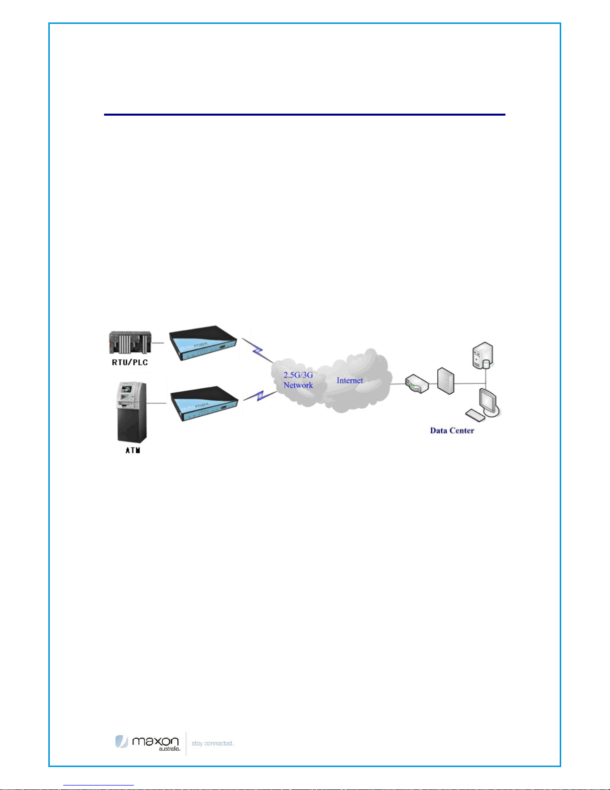
I n t r o d u c t i o n
MA100-1010 is a HSUPA Ethernet router providing data communications
via the public cellular network.
The MA100-1010 utilises an industrial 32-bit CPU embedded with a real
time operating system. The device supports RS232 connection, four
Ethernet ports and wifi that conveniently and transparently connect one
device to a cellular network, allowing you to connect to your existing
serial and Ethernet devices with minimal configuration.
The MA100-1010 has been widely used within M2M applications, such as
intelligent transportation, smart grid, industrial automation and telemetry.
Features and Benefits
Design for Industrial Application
Industrial cellular module EM770W
High-powered industrial 32bit CPU
Industrial GPS module
Supports low power consumption mode, including sleep mode.
Metal housing.
Voltage range:5~35VDC
Auto recovery functionality, including online detection, and auto
redial.
Ethernet port: 1.5KV magnetic isolation protection
RS232: 15KV ESD protection
SIM port: 15KV ESD protection
Page 9

Page - 9 -
Power port 2.5mm Barrel connector: reverse-voltage and
overvoltage protection
Antenna port SMA Female
Supports IP Stack Auto mode
IP / web based user interface for remote management,
maintenance and configuration.
Standard and Convenience
Supports standard RS232, Ethernet ports and Wi-Fi.
Supports standard WAN port and PPPOE protocol that can
connect to ADSL directly
Supports intellectual mode, establishes communication state
automatically when powered on
Provide management software for remote management
Convenient configuration and maintenance interface (WEB or CLI)
High-performance
Supports double link backup between two cellular networks
Supports triple link backup among cellular, cellular and
WAN(PPPOE, ADSL)
Supports VPN client(PPTP, L2TP, IPSEC and GRE)
Supports port mirror function
Supports WIFI AP, WIFI AP client and WDS
Supports multi online trigger ways, including SMS, ring and data.
Support slink disconnection when timeout
Supports APN/VPDN
Supports wireless video monitoring and dynamic picture transfer
Supports DHCP server and client, DDNS, firewall, NAT, DMZ host,
etc.
Supports TCP/IP, UDP, ICMP, SMTP, HTTP, POP3, OICQ, TELNET, FTP,
SNMP protocols
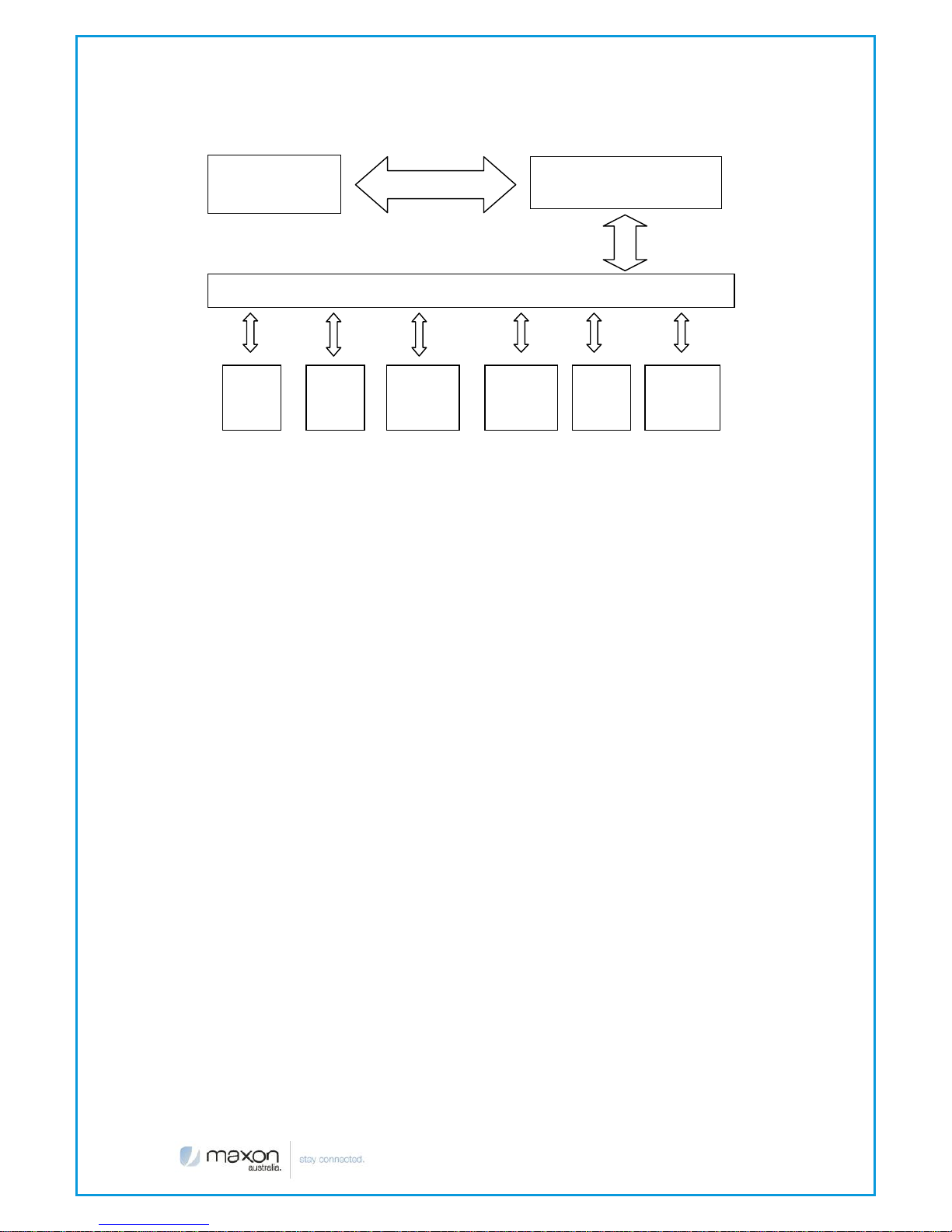
Router chart is as follows
Page 10
Page - 10 -
Embedded processing
`system
Power
RS232
Indicator
lights
DATA Interface
User interface
4 ports
switch
WIFI
AP
10/100M
WAN
Cellular
Module
Page 11

Page - 11 -
S p e c i f i c a t i o n s
Cellular Specification
Standard and Band
Bandwidth
TX
power
RX
sensitivity
MA100-1010 GPS+WCDMA ROUTER
UMTS/WCDMA/HSDPA/
HSUPA
850/1900/2100MHz,
850/900/1900/2100MHz
GSM850/900/1800/1900
MHz
GPRS/EDGE CLASS 12
HSUPA: 5.76Mbps
(Upload speed)
HSDPA: 7.2Mbps
(Download speed)
UMTS: 384Kbps
(DL/UL)
<24dBm
<-109dBm
WIFI Specifications
Standard
IEEE802.11b/g
IEEE802.11n (optional)
Bandwidth
IEEE802.11b/g: 54Mbps (max)
IEEE802.11n: 300Mbps (max)
Security
WEP, WPA, WPA2, etc.
WPS (optional)
TX power
16-17dBm(11g), 18-20dBm(11b)
RX sensitivity
<-72dBm@54Mpbs
Hardware System
CPU
Industrial 32bit CPU
FLASH
4MB(Extendable to 16MB)
SDRAM
32MB(Extendable to 64MB)
Interface Type
Ethernet
1x 10/100 Mbps Ethernet port(RJ45), auto MDI/MDIX,
1.5KV magnetic isolation protection
LAN
4 10/100 Mbps Ethernet ports(RJ45), auto MDI/MDIX,
1.5KV magnetic isolation protection
Serial
1 RS232 port, 15KV ESD protection
Data bits: 5, 6 ,7, 8
Stop bits: 1, 1.5, 2
Parity: none, even, odd, space, mark
Baud rate: 110~230400 bps
Indicator
"Power", "System", "Online", "GPS", " Local Network ",
"WAN", "WLAN"
Page 12
Page - 12 -
Antenna
Cellular: 2 x Standard SMA female interface, 50 ohm,
WIFI: Standard SMA female interface, 50 ohm,
SIM
2 x Standard 3V/1.8V user card interface with 15KV
ESD protection
Power
Standard 3-PIN power jack, reverse-voltage and
overvoltage protection, 2.5mm barrel connector
Reset
Restores the router to its original factory default
settings
Power Input
Standard Power
DC 12V/1.5A
Voltage Range
DC 5~35V
Current
Consumption
Minimum current: 450mA (12VDC)
Maximum Current: 600mA (12VDC)
* The product needs to be supplied by a limited
power source or the power supply provided.
Otherwise, safety will not be ensured
Physical Characteristics
Housing
Metal
Dimensions
206x135x28 mm
Weight
805g
Environmental Limits
Operating Temperature
-25~+60ºC
Extended Operating Temperature
-30~+75ºC
Storage Temperature
-40~+85ºC
Operating Humidity
95% (Non condensing)
Page 13
Page - 13 -
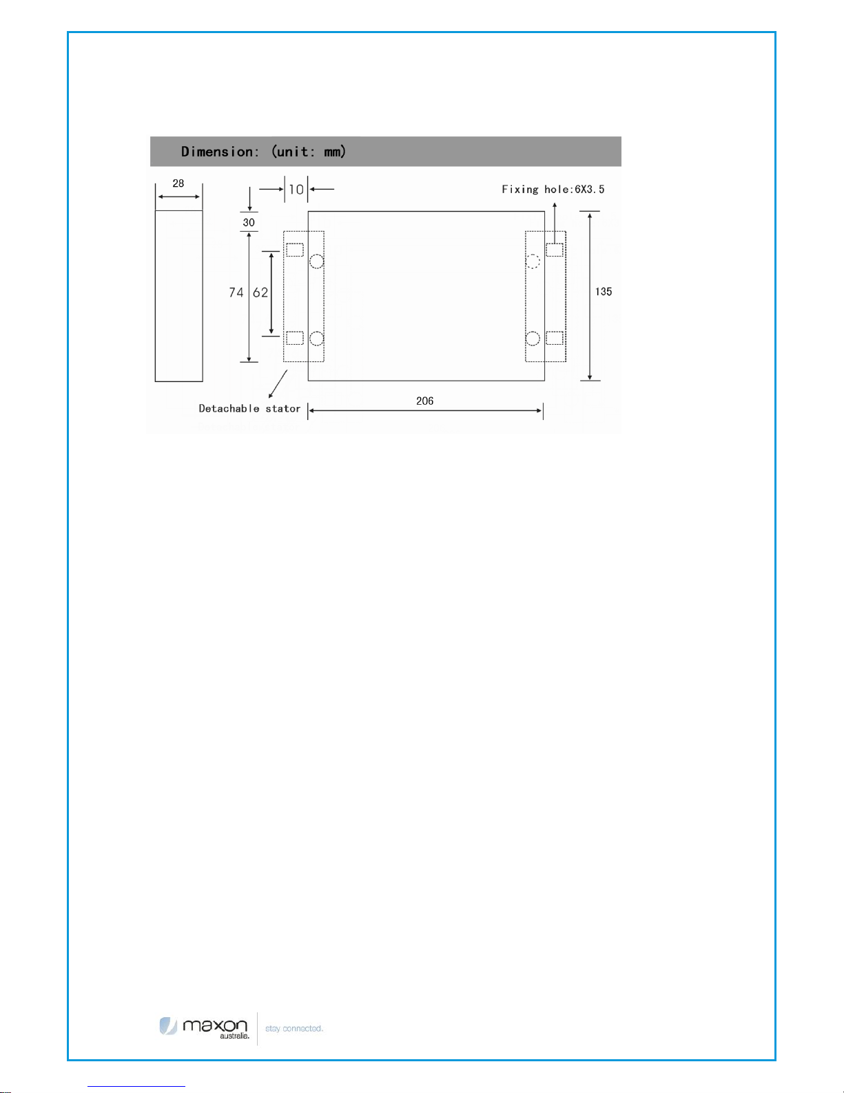
Dimension: (unit: mm)
Page 14

Page - 14 -
I n s t a l l a t i o n I n t r o d u c t i o n
Accessories List
Name
Quantity
Router
1
Cellular Antenna
1
GPS Antenna
1
WIFI Antenna
1
Network cable
1
Serial cable
1
Power Lead
1
Stator
2
SIM card Installation
Power off the router, and press the eject button next to the SIM card tray
with a small sharp object. Upon doing so the SIM card tray will eject from
the face of the modem. Place the SIM card into the SIM card tray
(Ensure that the side of the SIM card with the metal connection points is
facing upwards), and then insert the SIM card tray back into the SIM
card outlet.
Antenna Installation
Attach the SMA male connector of the cellular antenna into the female
SMA interface on the router labeled “Antenna”.
Attach the SMA male connector of the WIFI antenna into the female
SMA interface on the router labeled “WIFI”.
The router supports an RS232 interface and a 10/100M Ethernet interface.
These two interfaces both utilize an RJ45 connector, with the RS232
interface labeled “Console” and the 10/100M Ethernet interface labeled
“ETH”.
Plug the RJ45 end of the serial cable into the RJ45 outlet of the router
labeled “console”, and plug the DB9F end of the serial cable into the
RS232 serial interface of the user’s device.
Page 15

Page - 15 -
The pin out connections of the serial cable are as follows:
RJ45
DB9F
1
8
2
6
3 2 4 1 5
5
6 3 7
4
8
7
The signal definition of the DB9F serial communication interface is as
follows:
Power
The input supply voltage range is 5~35VDC. We recommend using the
standard DC 12VDC/1.5A power adaptor available from Maxon.
Indicator Lights
The router has five indicator lights and operates as follows:
Indicator
Light
State
Status Description
Power
ON
Router is powered on
OFF
Router is powered off
System
BLINK
System is up
OFF
System is down
Pin
RS232 signal
Direction
1
DCD
output
2
RXD
output
3
TXD
input
4
DTR
input
5
GND
6
DSR
output
7
RTS
input
8
CTS
output
Page 16

Page - 16 -
Online-1
ON
The main link has logged onto the
network
OFF
The main link hasn’t logged onto the
network
GPS
ON
GPS is active
OFF
GPS is not active
Local
Network
1-4
OFF
The corresponding interface is not
connected
ON /
BLINK
The corresponding interface is
connected /Communicating
WAN
OFF
The WAN interface is not connected
ON /
BLINK
The WAN interface of is connected
/Communicating
WLAN
OFF
WLAN is not active
ON
WLAN is active
Reset Button
The modems “Reset” button is used to restore the modem to its
original factory default settings. To restore the router to factory default
settings, the user needs to press the “Reset” button and hold it in for 15s,
after which, the router will restore its original factory default settings and
restart automatically.
Page 17

Page - 17 -
C o n f i g u r a t i o n a n d M a n a g e m e n t
Datamax is configured via a web interface. In order to access the
Datamax web interface you will need a computer with a spare Ethernet
LAN port. The LAN card configuration should have the Internet Protocol
TCP/IP set to obtain an IP Address automatically and obtain DNS server
address automatically.
To check these settings go to your LAN adaptor properties and check
your Interment Protocol TCP/IP settings, it should look as follows:
Connection Steps:
1. Connect the Ethernet cable supplied with your router to your
computer Ethernet LAN port
2. Your computer will get an IP address from the Datamax DHCP
range automatically.
Page 18

Page - 18 -
3. In your web browser type 192.168.1.1 in the Address (URL) field (The
Default IP Address of the Ethernet port is 192.168.1.1). The router will
prompt you for login credentials the default username and
password are both “admin”.
WAN Settings
This page is used to configure the Internet access parameters
User Name
Username provided by the ISP
Password
Password provided by the ISP
Call Center
Telephone number to dial default *99#
APN Name
Select APN Name provided by the ISP is
Network
Select
Auto, GSM only and WCDMA only
Pin Verify
Enable
Enabling and entering the PIN no. will
disable the PIN code
WAN NAT
Enable/Disable
Page 19

Page - 19 -
Internet IP Address
By default, the Internet IP Address of the router is allocated by the ISP
automatically. Should your connection require a static IP address you
can set the address if the ISP supports this feature.
Domain Name Server (DNS) Address
Normally, the Domain Name Server (DNS) Address of the router is
allocated by the ISP automatically. You can also use your own DNS
address.
If you want to use your own DNS, please make sure that the DNS address
is accessible.
Keep Online Detection
This function is used to detect whether the Internet connection is active.
Once enabled and the router detects that the connection is inactive, it
will redial automatically to re-establish a data connection.
Detection Method:
None
Detection is disabled
Ping
The router will send an ICMP packet to the primary
Page 20

Page - 20 -
server, if it fails it will try the secondary detection server,
if the router does not receive ICMP response it will try to
reconnect to the network.
Route
Using the route method, the router will use a trace route
method for detecting the connection status by trying to
reach the primary and secondary detection servers.
PPP
Detects data connection status. With this method, the
router will monitor the PPP connection layer status.
Detection
Interval
Is the time interval between status checks, the value is
represented in seconds
Primary
Detection
Server IP
Is the address of the server used to respond to the
router’s detection packets. This item is only valid for
"Ping" and "Route" methods
Backup
Detection
Server IP
Is the address of the secondary server used to respond
to the router’s detection packets. This item is only valid
for "Ping" and "Route" methods
Note: with “Route” or “Ping” detection methods, it is quite important to
make sure that the “Primary Detection Server IP” and “Backup Detection
Server IP” are reachable, as they have to respond to the router.
Page 21

Page - 21 -
WIFI Settings
WIFI Enable
Enables or disables the WIFI
Name (SSID)
Service Set Identifier which is also known as the
wireless network name, A value of up to 32
alphanumeric characters.
Hide SSID
SSID undetectable if enabled
Region
This item determines where the router is used,
please choose the correct region
Channel
Determines which operating frequency to use
Mode
G and B: Provides backward compatibility with the
slower 802.11b wireless devices while still enabling
802.11g communications.
B only: Supports the slower 802.11b mode only.
G only: Supports 802.11g mode only.
Disable
No wireless security
WEP
Wired Equivalent Privacy
WPA-PSK
WI-FI Protected Access Pre-Shared Key
WPA2-PSK
WI-FI Protected Access Pre-Shared Key
WPA/WPA2-PSK
WI-FI Protected Access Pre-Shared Key
Page 22

Page - 22 -
Configure WEP Wireless Security
The WEP configure page is as follows:
Authentication Type: Open System, Shared Key or Automatic
Security Encryption (WEP) Key: WEP encryption key, It should be 5 or 13
characters.
Configure WPA-PSK Wireless Security
The WPA-PSK configure page is as follows:
Page 23

Page - 23 -
Encryption Method: TKIP, AES or AUTO.
Passphrase: A word or group of 8-63 printable characters
WPA2-PSK, WPA/WPA2-PSK configurations are the same as WPA-PSK.
LAN Settings
Under LAN settings, you can configure the router IP settings, enable or disable
DHCP services on the router.
DHCP services provide your devices with dynamic IP address every time you
connect the device to your router.
IP Address
The gateway IP Address of the router
IP Subnet Mask
The LAN interface subnet mask
MAC Address
The LAN port Ethernet MAC Address
Note: If you change the LAN IP Address, you will need to reboot the
router, making sure that you use the new IP address in your browser to
access the router web settings.
Use Router as DHCP
Server
Enables the router to operate as a DHCP server.
When disabled, the DHCP is turned off.
Starting IP Address
The starting IP Address of the DHCP server’s
Address pool
Ending IP Address
The ending IP Address of the DHCP server’s
Address pool
Page 24

Page - 24 -
Firewall
NAT
NAT (Network Address Translation or Network Address Translator) is the
translation of an Internet Protocol address (IP address) used within one
network to a different IP address known within another network. One
network is designated as the inside network and the other, as the outside
network. Typically, a company maps its local inside network addresses to
one or more global outside IP addresses and un-maps the global IP
addresses on incoming packets back into local IP addresses. This helps
ensure security since each outgoing or incoming request must go
through a translation process that also offers the opportunity to qualify or
authenticate the request or match it to a previous request. NAT also
conserves on the number of global IP addresses that a company needs
and it lets the company use a single IP address in its communication with
the world.
Adding a NAT item
Service Name:
The NAT entry name
Service Type:
The protocol used TCP or UDP or BOTH
Outside Starting Port:
Starting port number of the WAN incoming traffic
Inside Start Port:
Inside LAN start port number
Port Numbers:
Number of ports to be forwarded
Server IP Address:
LAN IP address that will be used for NAT
functionality.
Example:
Page 25

Page - 25 -
Configure an item as follows
Once you click Add Item, the NAT rule will appear in the Custom NAT
items table.
Based upon the above rule the router will process packets coming on
port 5001 to port 5003 directing the packets to 192.168.1.249
Deleting a NAT item
To delete a NAT item, you should select the item and press the “Delete
Item” button.
DMZ
DMZ page allows one IP address within the LAN to be exposed to the
internet without allowing unauthorized access to the local private
network. All traffic addressed to Datamax WAN IP will be passed to this
host.
Enable DMZ:
Enable or disable DMZ function.
DMZ IP:
IP Address of the target device.
Page 26

Page - 26 -
Packet Filter
This feature allows restricting/allowing packets from going in or out of
your LAN interface, this can be filtered at the IP or port level.
Enable Packet
Filter
Enable or disable “packet filter” function
Policy
You can select between Deny or Allow
Direction
Input: packet from WAN to LAN
Output: packet from LAN to WAN
or Both which will block or allow the ports from and to
the LAN.
Protocol:
Packet protocol type TCP, UDP or TCP/UDP
Source Port
Packet's source port
Destination Port
Packet's destination port
Source IP
Packet's source IP address. If this field is left empty,
the rule will apply on all incoming source IP addresses.
Destination IP
Packet's destination IP address, If this field is left empty
the rule will apply on all outgoing source IP addresses.
Note:
"Source Port" ,"Destination Port" ,"Source IP" ,"Destination IP" cannot all
be empty, you have to input at least one of these four parameters.
Example:
To block local PC with IP Address 192.168.1.249 telnet access (TCP port
23), the firewall/filter item must be configured as following:
Page 27

Page - 27 -
Change image and
interface on the router
The entry below is the configured firewall/filter representing the above
configuration
MAC Filtering
With Mac filtering you can allow or deny router and internet access
based on their MAC address, MAC address (A Media Access Control
address) is a unique identifier assigned to the network interfaces for
communications on the physical network segment.
Enable MAC
Filtering
Enable or disable MAC filtering function
Policy
You can select between Deny or Allow
MAC Address
Location where you add the MAC address which
you would like to Allow or Deny
Page 28

Page - 28 -
Static Routes
Static routes allows you to add an entry to the router routing table. This
can be used if you would like to configure a VPN tunnel or forward
packets to a particulate IP address on your LAN.
Press “Add” button to start add a custom static route:
Route Name
static route’s name, used for identification purpose
only
Destination IP
Address
The packet’s destination IP Address
IP Subnet Mask
Is the subnet mask for this destination IP. If the
destination is a single host, this should be set to
255.255.255.255
Gateway IP
Address
The gateway IP Address for this route
Metric
A number between 1 and 15, which represents the
number of routers between your network and the
destination.
If you want to delete a custom static route, choose this item and press
“Delete” button.
Page 29

Page - 29 -
Router Status
This page displays the router’s status information. As per the below
image
Page 30

Page - 30 -
System
Firmware Version
Software version information
Module
The Wireless module used to connect to the internet
Signal
Packet protocol type TCP, UDP or TCP/UDP
Network
Packet’s source port
Internet Port
Status
WAN connection Online/ Offline
IP Address
WAN IP Address
Gateway
WAN Gateway Address
Domain Name
Server
The ISP DNS
LAN Port
IP Address
LAN IP Address
DHCP
Enabled/ Disabled
IP Subnet Mask
Subnet mask of the LAN IP Address
Wireless Port
Name
SSID name
Region
Country
Channel
Frequency that the WIFI operates on
Mode
802.11g and 802.11b
Wireless AP
Wireless AP is enabled/Disabled
Backup Settings
You can save your router configuration by clicking on the backup
button; this will prompt you to save the configuration file to your local
hard drive
Note: Do not edit the saved file. If the file used to restore configuration is
not correct, the router will restore to a factory default setting.
Page 31

Page - 31 -
To restore the router configuration from a file, click the “Browse” button
and select the configuration file you would like to restore. Click the
“Restore” button to initiate the restore process.
Load Default
Load defaults will reset the modem settings to the default factory
settings.
To restore the modem to Factory defaults click on “Load default” button
and confirm by clicking the “yes” button. The modem factory default
settings will be restored and the modem will reboot.
Router Upgrade
The routers firmware is stored on FLASH memory on the device and can be
upgraded as new firmware is released. If the upgrade file is compressed (.ZIP
file or .RAR), you must first extract the binary (.IMG) file before sending it to the
router. The upgrade file can be sent to the router using your browser.
To upgrade the firmware, click “Browse” and browse to the location of the
binary (.IMG) file, then click “Upload” to start the upgrade process.
Page 32

Page - 32 -
Note:
When uploading software to the Router, it is important not to interrupt the Web
browser by closing the window, clicking a link, or loading a new page. If the
browser is interrupted, it may corrupt the Router. It should not shutdown the
power supply when uploading. When the upload is complete, your router will
automatically restart and it will revert settings back to the factory defaults. The
upgrade process will take several minutes.
Set Password
The default username and password are both “admin”.
To change the username and password, type the new username, old
password and new password. Once this is done click the “Apply” button.
Logs
Logs allow you to view the router diagnostic information. You have the
option of viewing the log data on the web page, sending the log data
to an external server or sending the data to a serial console.
Page 33

Page - 33 -
Web Option
The log message is displayed on this web page. With the Web option,
you can save the output to a local file by clicking the “Save log” button.
Console:
The log message is sent to the console port. To use this function, you
should connect the router’s console port and your PC’s serial port with
the supplied serial cable. To view the logs you can open a terminal
software such as hyper terminal with the following serial port settings:
Baud: 115200 bps
Data bit: 8
Parity: None
Stop bit: 1
Flow control: None
When you configure the serial port settings, press the “call” button and
the router log message will be displayed on the terminal program.
Page 34

Page - 34 -
You can capture the log message into a file:
From the menu, choose “Transfer” ”capture text”
Input the log file name and press “start” button, the output message are
now stored in the log file.
When the messages are captured, you can stop capturing:
From the menu, choose “Transfer””capture text””stop”
Syslog:
Page 35

Page - 35 -
With this option enabled the log data will be sent to an external server.
You can use an external program similar to tftpd32, to capture the
modem log data.
Misc
The default Datamax web interface listens on port 80. To change the
default port, configure the “web config port” item.
To reboot the router, press the “Reboot” button.
VPN Setup
PPTP Client
Enable PPTP Client
Enable or disable PPTP VPN Client function
PPTP Server IP
The PPTP server’s IP Address
Local Tunnel IP
The local tunnel IP Address. “Auto” allocates the
local tunnel IP address from the PPTP Server
dynamically. You can also use the fixed local
tunnel IP if the PPTP Server supports it.
User Name
PPTP Server logon username
Password
PPTP Server logon password
Page 36

Page - 36 -
L2TP Client
Enable L2TP Client
Enable or disable L2TP Client function
L2TP Server IP (LNS)
The L2TP server’s IP Address
Local Tunnel IP
The local tunnel IP Address. “Auto” allocates the
local tunnel IP address from the PPTP Server
dynamically. You can also use the fixed local
tunnel IP if the PPTP Server supports it.
User Name
L2TP Server logon username
Password
L2TP Server logon password
IPSEC Client
IPSEC Client settings must be configured to match your VPN Server setup.
Below is a sample configuration.
Page 37

Page - 37 -
Dynamic DNS
Dynamic DNS is a method/protocol/network service that provides the
capability for a networked device, such as a router or computer system
using the Internet Protocol Suite, to notify a Domain Name System (DNS)
name server to change, in real time, the active DNS configuration of its
configured hostnames, addresses or other information
Page 38

Page - 38 -
To use this feature your carrier must provide you with a public dynamic IP
address. You will also need to sign up with a DynamicDNS service
provider.
Every time the router connects to the network, it will update its Dynamic
DNS host configuration as per the supplied settings.
Enable Dynamic DNS Service
Enable DDNS service
Service Provider
The DDNS service provider
Host Name
The DynDns provider’s server hostname
Customer Domain
Your custom DynDns domain name
User Name
Your DynDns account username
Password
Your DynDns account password
Update Interval
The time interval of IP Address update
The “Show Status” button is used to display the current DDNS status.
The above DDNS status page shows the domain name now pointing to
the IP Address 10.95.207.236
Page 39

Page - 39 -
Serial Settings
The console port on the Datamax is normally used for router debugging.
The console port can also be used as a standard serial port.
The data sent via the serial port is encapsulated by a TCP/IP protocol
stack prior to being sent to the destination server. This function allows the
Datamax to operate as a DTU (Data Terminal Unit).
Serial port Settings:
Baud rate
The serial port baud rate supports
110,300,1200,2400,4800,9600,19200,38400,57600,115200
Data bit
data bit supports 8,7,6,5 data bit
Parity
parity supports odd and even parity
Stop bit
stop bit, supports 1 and 2 stop bits
Enable Serial
TCP Function
Enable the serial to TCP function
Protocol Type
Supports the following:
UDP(DTU) – UDP with heart beat mechanism
Pure UDP – Data transmit with standard UDP protocol.
TCP(DTU) -- TCP with Heart beat mechanism
Pure TCP -- Data transmit with standard TCP protocol
TCP Server: the Modem will be listening on the WANIP
address and defined port number
Server Address
The data service center’s IP Address or domain name
Server Port
The data service center’s listening port
Device ID
The router’s identity number
Page 40

Page - 40 -
Heartbeat
Interval
The time interval to send heart beat packet. Valid only
when you choose UDP(DTU) or TCP(DTU) protocol .
GPS Settings
Enable GPS
Enable or disable GPS function
GPS Output
Interface
You can send GPS data to the Network or the serial
interface
GPS Center
Address
The GPS Service Center IP address or domain name
GPS Center
Listening Port:
GPS Service Center listening port
GPS Information
Update Interval
The time interval between two GPS information
updates. Unit is seconds.
GPS Speed
Threshhold
GPS Speed Threshhold
Device ID
A device ID that can be sent with the GPS data
Serial Port
settings
Here you can setup the serial port baud rate, databit,
Parity, Stopbit and Flow control settings.
Enable GPS: Enable or disable GPS function
GPS Output Interface: This item selects the GPS output interface
including network and serial port
GPS Center Address: The GPS center’s IP Address or domain name
GPS Center Listening Port: The GPS center’s listening port.
GPS Information Update Interval (Seconds): The time interval between
two GPS information updates. Unit is seconds.
When GPS output interface is serial port, we should set the following serial
port settings:
Page 41

Page - 41 -
 Loading...