

Page 1

Intelimax+4G | M2M 4G CAT1 Serial Modem | MA-2020-4G
User Manual
Page 2

Intelimax+4G User Manual
- 2 -
TABLE OF CONTES T S
T A B L E O F C O NT E S T S ............................................................................................... 2
D I S C L A I M E R S ............................................................................................................... 3
R F E X P O S U R E A N D E L E C T R I C A L S AF E T Y .................................................... 4
C O N T A C T I N F O R M A T I ON ..................................................................................... 8
R E V I S I O N H I S T O R Y ................................................................................................... 9
I N T R O D UC T I O N ......................................................................................................... 10
Intelimax+ 4G Features ................................................................................................ 10
M O D E M S E T U P ........................................................................................................... 13
Connecting to the Intelimax+4G ............................................................................... 14
Modem Status Tab ....................................................................................................... 17
WAN Configuration TAB ............................................................................................... 19
Scheduler TAB ............................................................................................................... 24
Serial Configuration TAB .............................................................................................. 26
IP Stack Configuration TAB .......................................................................................... 28
Modem Emulation TAB ................................................................................................ 35
Dynamic DNS ................................................................................................................ 37
PPP Server ...................................................................................................................... 38
Administration TAB ........................................................................................................ 43
System TAB ..................................................................................................................... 47
Other GUI functions ...................................................................................................... 52
Firmware Upgrade ....................................................................................................... 55
SMS Commands ........................................................................................................... 56
Remote Mode Change via CSD Call ........................................................................ 59
LED Functionality ........................................................................................................... 61
Device Operation Checking / Troubleshooting ...................................................... 62
T E L N E T / S S H C O M M A N D S ................................................................................ 64
E X T E N D E D /I N T E L I M AX + S P E C I F I C AT C O M M A N D SET ( I P S T A C K
M O D E S ) .......................................................................................................................... 76
E X T E N D E D /MODEM S P E C I F I C AT C O M M A N D S E T ( I P a n d S E R I A L
M O D E S ) .......................................................................................................................... 91
Page 3

Intelimax+4G User Manual
- 3 -
DISC L A I M E R S
All data and information contained in or disclosed by this document are confidential
and proprietary information of RF Industries, and all rights therein are expressly
reserved. By accepting this material, the recipient agrees that this material and the
information contained therein are held in confidence and in trust and will not be used,
copied, reproduced in whole or in part, nor its contents revealed in any manner to
others without the express written permission of RF Industries. The information provided
in this document is provided on an “as is” basis.
In no event will RF Industries be liable for any damages arising directly or indirectly from
any use of information contained in this document. Information in this document is
subjected to change without any notice.
Life support – This product is not designed for use in life support appliances or systems
where malfunction of these products can reasonably be expected to result in personal
injury.
RF Industries’ customers using or selling these products for use in such applications do
so at their own risk and agree to fully indemnify RF Industries for any damages resulting
from such application.
Right to make change - RF Industries reserves the right to make changes, without
notice, in the products, including circuits and software, described or contained herein
in order to improve design and/or performance.
Some features outlined in this manual may require an updated firmware and/or GUI to
work. Please contact RF Industries for more information.
Page 4

Intelimax+4G User Manual
- 4 -
RF E X P O S U R E AND E L E C T R I C AL S A F E T Y
The use of this modem in any other type of host configuration that may not comply
with the RF exposure requirements should be avoided. During operation, a minimum of
20 cm (8 inches) should be maintained between the antenna, whether extended or
retracted, and the user’s/bystander’s body (excluding hands, wrists, feet, and ankles)
to ensure RF exposure compliance in accordance with ARPANSA guidelines. The
modem is not designed, nor intended, for use in applications within 20 cm (8 inches) of
the body of the user. Continued operational compliance of the modem relies upon it
being used with an AS/NZS 60950.1 approved SELV power supply.
Cautions
This modem has been tested and found to comply with the limits pursuant to relevant
ACMA Standards. These limits are designed to provide reasonable protection against
harmful interference in an appropriate installation. This modem generates, uses, and
can radiate radio frequency energy and, if not used in accordance with instructions,
can cause detrimental interference to other radio communication networks and
devices. Use only the supplied or approved antenna. Unauthorized antennas,
modifications, or attachments could impair performance, damage the modem, or
result in violation of RF exposure regulations.
There is no guarantee that electromagnetic interference will not occur in a particular
installation. If the modem does cause detrimental interference in radio and television
reception, which can be verified by turning the modem on and off, the user is
encouraged to try to correct the interference by one or more of the following
measures:
▪ Re-orient or relocate the receiving radio or TV antenna
▪ Increase the separation between the modem and the receiver
▪ Contact RF Industries Maxon Technical Support for assistance.
Changes or modifications to the modem that are implemented without the express
consent of RF Industries Pty. Ltd. void the product warranty and terminate the user’s
authority to use the modem.
Page 5

Intelimax+4G User Manual
- 5 -
General Safety
RF Interference Issues: Avoid possible radio frequency (RF) interference by carefully
following safety guidelines below:
▪ Switch OFF the modem when in an aircraft. The use of cellular devices in an
aircraft is illegal. It may endanger the operation of the aircraft and/or disrupt
the cellular network. Failure to observe this instruction may lead to suspension or
denial of cellular services to the offender, legal action, or both.
▪ Switch OFF the modem in the vicinity of gasoline or diesel fuel pumps or before
filling a vehicle with fuel.
▪ Switch OFF the modem in hospitals and any other places where medical
equipment may be in use.
▪ Respect restrictions on the use of radio equipment in fuel depots, chemical
plants, or in areas of blasting operations.
▪ There may be hazards associated with the operation of your modem in the
vicinity of inadequately protected personal medical devices such as hearing
aids and pacemakers. Please consult the manufacturers of the medical device
to determine if it is adequately protected.
▪ Operation of the modem in the vicinity of other electronic equipment may
cause interference to the equipment if it is inadequately protected. Observe
any warning signs and manufacturers’ recommendations.
▪ The modem contains sensitive electronic circuitry. Do not expose the modem
to any liquids, high temperatures or shock. The modem is not waterproof.
Please keep it dry and store it in a cool, dry place.
▪ Only use original accessories or accessories that are authorized by the
manufacturer. Using unauthorized accessories may affect your modem’s
performance, damage your modem and violate related national regulations.
▪ Always handle the modem with care. There are no user serviceable parts inside
the modem. Unauthorised dismantling or repair of the modem will void the
warranty.
Page 6

Intelimax+4G User Manual
- 6 -
NOTE:
Vehicle Safety
▪ Do not use the modem whilst driving.
▪ Respect national regulations on the use of cellular devices in vehicles. Road
safety always comes first.
▪ If incorrectly installed in a vehicle, the operation of the modem could interfere
with the correct functioning of vehicle electronics. To avoid such problems,
ensure that the installation has been carried out by qualified personnel.
▪ Verification of the protection and interference-free performance of vehicle
electronics should be a part of the installation procedure
Potentially Unsafe Areas
Posted Facilities: Turn off the modem in any facility or area when posted notices require
you to do so.
Blasting Areas: Turn off the modem where blasting is in progress. Observe restrictions
and follow any regulations or rules.
Potentially Explosive Atmospheres: Turn off the modem when you are in any area with a
potentially explosive atmosphere. Obey all signs and instructions. Sparks in such areas
could cause an explosion or fire, resulting in bodily injury or death.
Areas with a potentially explosive atmosphere are often but not always clearly marked.
They include:
▪ Fuelling areas such as gas or petrol stations
▪ Below deck on boats
▪ Transfer or storage facilities for fuel or chemicals
▪ Vehicles using liquefied petroleum gas, such as propane or butane
* The product needs to be supplied by a limited power source or the
power supply provided. Otherwise, safety will not be ensured.
* Do not affix the modem in an open area where it is liable to lightning-
strike hazard.
Page 7

Intelimax+4G User Manual
- 7 -
▪ Areas when the air contains chemicals or particles such as grain, dust or metal
powders
▪ Any other area where you would normally be advised to turn off machinery of
any kind
Concentrated Electromagnetic Activity: Avoid using the modem within areas of high
electromagnetic wave activity or within enclosed metallic structures e.g. lifts.
Page 8

Intelimax+4G User Manual
- 8 -
CON T A C T I N FORM A T I O N
In keeping with RF Industries’ dedicated customer support policy, we encourage you
to contact us.
TECHNICAL:
Hours of Operation: Monday to Friday 8.30am to 5.00pm*
Telephone: +61 2 8814 2300
Facsimile: +61 2 9630 0844
Email: support@maxon.com.au * Public holidays excluded
SALES:
Hours of Operation: Monday to Friday 8.30am to 5.00pm*
Telephone: +61 2 8814 2300
Facsimile: +61 2 9630 0844
Email: sales@maxon.com.au * Public holidays excluded
WEBSITE: www.maxon.com.au
ADDRESS:
RF Industries Pty Ltd
99 Station Road
Seven Hills NSW 2147
Australia
POSTAL ADDRESS:
RF Industries Pty Ltd
Locked Bag 2007
Seven Hills NSW 1730
Australia
Page 9

Intelimax+4G User Manual
- 9 -
REVI S I O N H I STOR Y
Product
Intelimax+4G M2M LTE CAT1 Serial Modem
Model
MA-2020-4G
Document Type
PDF
Current Version Number
1.11
Status of the Document
Release
Revision Date
March 2018
Total Number of Pages
94
- Revision History
Level
Date
History
1.00
Nov 2017
Initial Release
1.10
Dec 2017
Content and format improvement
1.11
Mar 2018
Updated Safety Statement
Page 10

Intelimax+4G User Manual
- 10 -
INT R O D U C T I ON
Breaking the industry benchmark, the top-of-the range Intelimax+4G is a unique and
intelligent fusion of 4G capabilities with advanced functionality of a modem/router.
Intelimax+ 4G Features
General Features
▪ LTE-FDD CAT 1Wireless Module (10Mbps downlink, 5Mbps uplink)
▪ Supports Packet and Circuit Switched Data*
▪ RS232 and RS485 (half/full duplex) Software Configurable
▪ 2-Way SMS
▪ Remote SMS diagnostics & reset
▪ Embedded TCP/IP, UDP/IP STACK
▪ Programmable periodic reset and other watchdog features
▪ Save and restore modem configuration from a file
▪ FOTA - Firmware upgrade over the air
▪ External antenna connectivity to maximise coverage
▪ External LED to show Signal Strength, Data Transfer and Connection status
Extended Features
▪ Remote CSD to IP Changeover
▪ Programmable WAN connection scheduler and periodic reset
▪ Configurable ping checking function
▪ Modem Emulation
▪ AT over IP
▪ FTP Client, SSH, and Telnet support
▪ SNMP v2 and SNMPv3
▪ SNTP
▪ Dynamic DNS
▪ PPP Server
▪ Secure Syslog and RSSI Logging
Security Features
▪ Encrypted access and configuration control
▪ Password Protected AT Commands
▪ SNMPv3 supports SHA and AES
Page 11

Intelimax+4G User Manual
- 11 -
▪ SSLv3 Encrypted Serial Socket
▪ Secure Syslog Client RFC5425, RFC5425 and RFC6587
▪ Login brute force detection and rejection
▪ Login activity log
Frequency Bands
▪ FDD-LTE B1/B3/B5/B7/B28
▪ WCDMA/HSPA+ B1/B5
Data Speeds
▪ LTE-FDD: UL 5Mbps / DL 10Mbps
▪ HSPA+: UL 5.76 Mbps /DL 42 Mbps
▪ UMTS: UL 384 Kbps / DL 384 Kbps
Physical
▪ 71mm x 55mm x 26mm (without side brackets and antenna port)
▪ Side mounting brackets
▪ Normal Operation Temperature: -30 to 60 °C
Connections
▪ RJ45 Connection
▪ USB Connection
▪ SIM Card Holder
▪ Antenna connector: SMA female
LED Lights
▪ Power/RSSI – dual colour indicates RX data received from serial
▪ Data – dual colour indicates TX data sent to serial
Approvals / Compliance
▪ ACA (both modem and module)
▪ FCC (module only)
▪ GCF (module only)
▪ PTCRB (module only)
▪ CE (module only)
▪ Carrier Approvals* - (Please contact RF Industries for more information)
▪ RoHS Compliant (both modem and module)
Power Source
▪ DC Input Voltage Range: 7 to 48 VDC
Page 12

Intelimax+4G User Manual
- 12 -
▪ Idle Current @ 12V: 80mA
▪ Maximum Current @ 12V: 150mA
Operating Systems
▪ Windows XP/ Vista / 7 / 8 / 10
Page 13

Intelimax+4G User Manual
- 13 -
MODE M S E T U P
Intelimax+ serial modem supports a Windows GUI software, where by you can configure
the modem via serial/USB connection or remotely via the WAN IP.
Maxon recommends using the GUI connected via a TCP/IP connection in order to utilise
all the configuration settings. When connecting to the Intelimax+ using the GUI when the
modem is in serial modem mode, there will be very limited functionality.
After connecting to the modem using the GUI, users can configure; WAN settings,
Scheduler, IP Stack, SNMP Dynamic DNS and Admin settings.
Page 14

Intelimax+4G User Manual
- 14 -
Connecting to the Intelimax+4G
TCP/IP Connection - Recommended
Using the TCP/IP connection option allows users to connect to the modem via an IP
connection. Firmware upgrades can ONLY be done when connected via TCP/IP.
Local Connection
To use this feature locally you must follow the following steps:
1. Plug in modem RJ45 power/serial cable then mini USB cable in this order
2. Install USB/LAN drivers which can be downloaded from:
http://www.maxon.com.au/product-supports/drivers-and-manuals.html
3. Set a static IP address to the modem:
Once the drivers are installed you will have to set a static IP on the Intelimax+
network connection (as the Intelimax+ does not support DHCP)
4. The default IP for the Intelimax+ is 192.168.10.1, set your IP within this range
Eg.192.168.10.50
5. Connect the GUI to the modem after modem has booted (1-2 minutes after
powered)
The default settings are: Address: 192.168.10.1 (Intelimax+ LAN IP address), Port:
10918, ID: admin, Password: admin. The password has to be re-entered when
opening the GUI each time.
Note: If all modem settings are not loaded into the GUI after connection, click the ‘Load
from Modem’ button at the bottom to refresh the settings.
Remote Connection
Users can also access the Intelimax+ remotely via a static IP address (e.g. maXwan) or
via a url (e.g. DynDNS):
Page 15

Intelimax+4G User Manual
- 15 -
Serial Port Connection
Use this section to connect to the modem using the provided RJ45 power/serial cable,
the default connection settings are:
Baud Rate: 115200
Data Bits: 8
Parity: None
Stop bit: 1 bit
Flow control: None
Make sure to select the correct COM port and click the open button, the Intelimax+ GUI
will connect to the modem via the selected COM port. The GUI can also perform a
search for the correct baud rate if it is not known.
The configuration operations available over a serial connection to the modem are
limited when compared to a TCP/IP connection.
Page 16

Intelimax+4G User Manual
- 16 -
GUI Connection Troubleshooting
1. What if I don’t know the serial interface to the modem?
The modem has a default baud rate of 115200, if you are not able to connect via
the serial interface at any baud rate, then restore the modem to factory defaults
by holding down the reset button for more than 20 seconds (5 second hold is for
profile reset).
2. Why does the Intelimax+ GUI not connect and reports “The attempt to connect was
forcefully rejected”?
If the Intelimax+ GUI connection to the modem is not closed with a TCP
disconnect the modem may reject connections and report with a message “The
attempt to connect was forcefully rejected”. This occurs until the modem TCP
timeout occurs which will be either via a modem reboot or after at least 10
minutes. If the connection is local you can shorten this time by reconnecting the
USB interface or under network connections, selecting the LAN interface to the
modem, disabling, then enabling this interface.
3. Why does the Intelimax+ GUI show that the device is discovered but not connect?
The LAN interface to the modem needs to be configured correctly. This may
involve setting a static IP address to the modem, such as 192.168.10.50 or
removing an incorrect address. The GUI will continue to try to connect to the
modem 3 times after the ‘Open’ button is pressed.
4. Why is the GUI not detecting the Intelimax+?
The Intelimax+ must be powered via the RJ45 connector, then the USB plugged
in, after approximately 1 minute, the PC will prompt for drivers to be installed. The
Intelimax+ requires the USB/LAN interface drivers installed to be able to talk via a
TCP IP connection to the modem, which can be downloaded from the Maxon
website.
There are times where the RNDIS network interface is present under network
connections but not when checked via a command line (ipconfig). If this is the
case then the PC must be restarted as the Microsoft Windows RNDIS driver is not
functioning correctly.
Page 17

Intelimax+4G User Manual
- 17 -
Modem Status Tab
The modem status page displays modem information such as network registration and
WAN connectivity status.
Information displayed on the Status page is:
Up time: Length of time since modem last rebooted (soft or hard)
System time: Recovered from the internal cellular module (or NTP server if SNTP
time client is enabled)
IMEI: IMEI number of the Intelimax+
Version: Firmware version output, includes versions and compile date.
E.g.
2.3.5
[201711022128]
H/W Version: Product’s board release version
Module Version: Cellular engine’s firmware version
Network registration: Shows registration status and carrier
Mode: Will show if modem is in packet switched or serial modem
Page 18

Intelimax+4G User Manual
- 18 -
PIN Status: Status of the SIM pin setting
Area information: LAI, LAC, Cell ID
Server status: Will display whether modem is in listening or connected states
Call status: In serial modem mode will display whether modem is in
connected call.
WAN IP: IP address assigned by carrier
Signal Level: Status of current signal strength (dBm).
Also shows the average, max and min over the last 15 minutes
(time can be modified on admin page)
Mode: IP Stack Mode of Intelimax+. (IP Stack Auto or Manual)
Sent/Received Packets: Shows the packet count and number of bytes sent and
received.
Extra: If secure socket or secure syslog certificates have been installed
to the modem then they are displayed here.
Page 19

Intelimax+4G User Manual
- 19 -
WAN Configuration TAB
WAN configuration page is used to configure how the modem will connect to the
3G/4G network. Please select the correct operation mode as this will decide if the
modem will automatically connect to the network on power up or work in pass through
mode.
The Intelimax+ supports 6 operation modes:
1. IP Stack Auto mode
2. IP Stack Manual mode
3. Serial mode (Pass-through/Transparent)
4. PPP WAN Auto mode
5. PPP WAN Conditional mode
6. PPP WAN Manual mode
Page 20

Intelimax+4G User Manual
- 20 -
IP Stack Auto Mode
When using IP STACK Auto the modem will behave as an IP Serial modem. When using
this mode the modem will transfer all incoming packets via the serial port to the host and
vice versa. The modem connects to the 3G/4G networks and acquires an IP address and
then runs the IP STACK server or client mode.
Intelimax+ IP Stack can be configured as a Server or Client mode. In Server mode, the
Intelimax+ will act as a socket server. The modem will listen on a specific TCP/UDP port
waiting for an incoming client socket connection. As soon as the client drops the socket
connection, the Intelimax+ will go back to socket listening mode as per IP stack
configuration. On the other hand, with client mode the Intelimax+ will try to establish a
socket connection to a preconfigured server IP address or DNS name and port number.
The client mode also supports a secondary server IP address just in case the primary
server cannot be reached. The in-built IP stack feature supports smarts such as PPP link
check, TCP link check, PPP link timeout, TCP link timeout and MTU settings.
Secure socket using SSLv3 can be used in both these modes as well as IP Stack Manual
Mode. Further detail on how to configure secure socket is in the IP Stack tab section.
IP Stack Manual Mode
With IPStack manual mode, the modem doesn’t initiate the PPP connection. The modem
will rely on the host on serial port to send the PPP initiation commands and acquire a
WAN IP connection.
The AT command to start the PPP session and open a socket is AT$$IPCTOS. The AT
command to close the socket and PPP session is AT$$IPCTCS.
Further AT command detail is included at the end of this manual.
Serial Modem Mode (Transparent / Pass-through)
This mode allows for the serial interface to connect through to the cellular module in the
modem. In this mode, the Intelimax+ processor still has some control and processing
abilities over the serial AT commands and connection processes. Used for Packet
Switched Date (PPP Pass-through) or Circuit Switched Data (CSD).
Circuit Switch Data Call
Circuit switch is a legacy style of communication where the user dials in to the modem
data terminating number. Circuit Switched Data call only operates under 3G network.
Standard set of AT commands used with Circuit Switch Call:
ATD Dial the Data number
Page 21

Intelimax+4G User Manual
- 21 -
ATA Answer the Data Call
ATS0=n Set auto answer where n=number of rings
+++ Escape command to enter AT command mode (1 second gap both
before and after command required to distinguish from data)
ATH Drops the data call
ATO Can return to call if still active
To use this feature please ensure the following has been setup on the SIM:
1. Contact SIM service provider and make sure that CSD is activated on the Sim
card. Generally, this requires a second number (data terminating number)
attached to the same service.
2. Configure the modem to auto answer the call or make sure that the equipment
connect to the modem has auto answer activated to detect an incoming call
and sends ATA to answer the data call.
Packet Switched Data Call
The Intelimax+ supports PPP over serial connections through the modem and utilizes
standard AT commands for this purpose. It is recommended that user dial out control
code executes a hang up process command before each reconnection attempt by
issuing a +++ command followed by and ATH command.
Standard set of AT commands used with PPP call: ATD Dial the PPP number (e.g.
*99#)
+++ Escape command to enter AT command mode (1 second gap both
before and after command required to distinguish from data)
ATH Drops the data call
ATO Can return to call if still active
When using a PPP dial up connection from the modem, the following commands have
to be issued before starting the connection:
AT+CGDCONT=1,"IP","apn" Set the access point name (APN).
AT^SGAUTH=1,auth_type,"userid","password”
Set the Authentication. auth_type can be: 0 - NONE, 1 - PAP, 2 – CHAP.
PPP Server Options
The Intelimax+ can be configured to act as a local PPP Server over the serial interface
with an independent WAN connection. There are three different PPP modes the modem
can operate in, which are all outlined further in the PPP Server section:
1. PPP WAN Auto mode: Modem is a PPP server over serial with the WAN IP
connection automatically connected.
Page 22

Intelimax+4G User Manual
- 22 -
2. PPP WAN Conditional mode: Modem acts as PPP server with the WAN IP
connection conditional on the serial PPP connection.
3. PPP WAN Manual mode: Modem acts as PPP server and the WAN IP connection
can be controlled via AT over IP commands.
WAN Connection Retries
The modem will reboot itself if it fails to get WAN IP after a pre-defined numbers of retries.
This can be configured in Retry times field. The default times is 10 and can be set from 2
to 100. The retry times can also be set via AT command us AT$$RETRYTO.
Band Change
When band changing two reboots may be required. The first reboot will save the setting
to the module and second reboot will apply the changes to the module so that module
will register to the selected band.
Only bands which are supported by the module will be displayed in this section.
Other WAN Related Settings
WAN page also allows configuring the following features:
• APN and dialup string
• Username and password for IP WAN
Invalid password characters list
“ (double quotation mark)
‘ (quotation mark)
? (question mark)
( ) (bracket)
@ (at sign)
; (semi colon)
|(pipe sign)
I (upper case |)
• Auto pin settings (Intelimax+ will enter the PIN code if SIM pin is Enabled. May
require a soft reboot to enable).
• Network authentication information
Page 23

Intelimax+4G User Manual
- 23 -
• Watchdog (Ping Function)
• Back off timer
• Periodic reset
o Can be enabled or disabled
o Configurable by number of hours between 1 and 28
• Reset state setting. Reset will happen in any state unless configured otherwise by:
o If the modem is in serial mode and in a connected state then the modem
will wait for the connection to drop before resetting.
o If neither ‘TCP Server Listening’ nor ‘TCP Connection State’ check boxes
are set, the modem will reboot in any IP state.
o TCP Server Listening – For use in IP Stack Auto or Manual Server mode – If
checked will wait until TCP connection is dropped by either server or client
before performing the reset.
o TCP Connection State – For use in IP Stack Auto or Manual Client mode – If
checked will wait until Intelimax+ client drops connection to a server or
server drops connection before performing the reset.
• Scheduled Time
o When ticked, the modem will reboot at the defined time whining a day.
The reboot will be taken place regardless of the TCP connection status.
• Battery
o When ticked, modem will enter idle mode (cellular module and serial port
are switched off) when battery voltage is below 11.9V. Modem will be
back to normal after battery voltage is over 12.3V.
Page 24

Intelimax+4G User Manual
- 24 -
Scheduler TAB
The scheduler tab allows configuring modem WAN connection schedule. The scheduler
supports two methods of selection. Days of the Week (setup to come on certain days of
the week) or Setting up a certain power up duration (setup to come certain during the
hour).
Scheduler Day of the Week
Using this option the user can specify days of the week when the modem will connect to
the internet and would be online. The connection and disconnection time is in 24-hour
format. While using the scheduler the RS232 and the 4G module can also be configured
to shutdown to save power.
To setup Scheduler by Day of the week, select the Day with connect and disconnect
times. You can also set the modem to power off itself when it disconnects, by checking
the power off check box. To delete an entry, click on the entry and press the Remove
selected Item button, or if you want to remove all entered entries click the “Remove ALL”
button.
Page 25

Intelimax+4G User Manual
- 25 -
Scheduler by Duration
Using this method, the modem will be powered up for a certain duration, then power
itself down for another period of time, and the cycle repeats itself.
To setup scheduler by duration enter for how long you wish the modem to stay powered
up and enter power cycle duration. The power down will be calculated by the modem.
In the below example the modem will stay powered for 5 min, power down for 25 min
and the cycle is repeated. (Range 0~60 minutes)
Page 26

Intelimax+4G User Manual
- 26 -
Serial Configuration TAB
The Serial configuration page is used to setup modem serial settings such as baud rate,
serial messages, and SMS on boot.
Serial Port Settings
Serial port setup includes the following:
Baud rate (supports 1200, 2400, 4800, 9600, 19200, 38400, 57600 and 115200)
Data Bit (5, 6, 7, or 8bit)
Stop bit (1or 2bit)
Flow Control (None or Hardware)
Serial port speed setup should be set to match host (connected via serial port)
configuration. With certain applications, there may be a need to fabricate a custom
serial cable to work between the host and the Intelimax+. The custom serial cable
Page 27

Intelimax+4G User Manual
- 27 -
depends on the equipment requirements and settings.
Other modem related settings include:
&D, S0, &C, Echo, and Q
Serial Password – Password protected AT commands
The Intelimax+ has the ability to password protect serial interface AT commands. The
serial password can be set on the serial tab. If AT commands need to be entered then
AT commands will return an ERROR message until the interface password is entered first
with the command, AT$$PWD=<password>. Once the password is entered the access
will persist for the session until the modem reboots. Further AT command detail in the AT
Command Password Protection section under the Intelimax+ specific AT Commands
section.
Boot up Message
The Intelimax+ boot up message “INTELIMAX READY” is a message that the modem
sends to the host via serial port upon boot up after a hardware power restart event.
Using this option the user can disable or enable this message.
Page 28

Intelimax+4G User Manual
- 28 -
IP Stack Configuration TAB
IP stack configuration page is used to setup modem IP STACK settings such as port
number and IP address and connection timeouts.
Protocols
IP Stack supports TCP and UDP, depending on your application requirement you can
choose between TCP and UDP communication
SSLv3 Option
If the SSLv3 check box is ticked, the Intelimax+ TCP/IP to serial converter applies
asymmetric cryptography to the socket connection using SSLv3. When using SSLv3 all
serial data transferred is encrypted in both client and server modes.
The SSLv3 certificates can be installed using the partial upload function in the GUI using
Page 29

Intelimax+4G User Manual
- 29 -
the following process:
1. Create the certification file for upload to the Intelimax+. The certificate files
should be placed into a folder along with a path.txt file.
2. The path .txt file should only contain the text “extra”.
3. Zip this folder, then upload to the Intelimax+ using the ‘Partial upload’ button in
the GUI, then reboot the modem.
4. Once the modem has rebooted the uploaded certificates can be seen on the
status page under the ‘Extra’ section.
Note: To remove the certificates, upload a .zip file with one file, a path.txt file with the
text “-extra”.
Note: If both SSLv3 IP Stack and secure syslog is used at the same time then the same
private key and certificate are used (the ca.pem certification file is not used by SSLv3).
How to generate SSL certificates
A SSL certificate can be generated using an application such as OpenSSL
(http://slproweb.com/products/Win32OpenSSL.html, the lite version is fine). To generate
certificate for client and key for client (key.pem, cert.pem):
C:\OpenSSL-Win32\bin>openssl req -new -x509 -days 3650 -nodes -config openssl.cfg out cert.pem -keyout key.pem
This application can be run from the command line for example: C:\OpenSSL-
Win32\bin>openssl req -new -x509 -days 365 -nodes -config openssl.cfg -out cert.pem -
keyout key.pem.
The resultant 2 certificate files contained in the /bin folder and are named: cert.pem and
key.pem.
IP Stack Modes
Intelimax+ supports operation of the IP Stack in either client or server modes:
Page 30

Intelimax+4G User Manual
- 30 -
• Server mode: In Server mode the modem will connect to a PPP session and will
listen on a predefined port for incoming client requests
• Client mode: the modem will initiate a PPP connection and try to connect to the
Primary server. If the connection to the server fails 10 times it will try the Secondary
server, if the connection to the secondary server also fails for 10 times the modem
will drop the PPP connection, reboot and start all over again.
Manual Auto Reconnect Client
Define whether the modem will automatically try to reconnect to TCP server if the socket
connection is dropped externally.
The Auto reconnection will be disabled if a socket disconnection command
(AT$$IPCTCS) is received from Serial Port.
Primary Server
Define the IP Address or DNS address of the primary server the Intelimax+ will try to
connect to in Client mode, in server mode please leave this field as default.
Secondary Server
Define the IP Address or DNS name of the secondary server the Intelimax+ will try to
connect to in Client mode, in server mode please leave this field as default.
Port Number
Define the TCP or UDP Port number, this port will be used in the server and client mode.
IP STACK Notifications
IP Stack notifications are by default sent out on the serial port to the connected host.
With some applications this may cause issues with data transfer and using this option the
user can disable or enable the notification messages.
TCP Session Control
Idle Timeout / Idle Timer: Enabling the idle Timeout and setting an Idle Timer, will set the
Intelimax+ to disconnect from a connected server (if configured as a client) or the
connection from a connected client (if configured as a server) if the modem receives no
Page 31

Intelimax+4G User Manual
- 31 -
data for the defined Idle Time period. Bear in mind that data could be continuously sent
from the modem to the connected device, but if nothing is received back, the modem
will disconnect. If the modem is connected as an auto-connect client then it will try to
reconnect to the server once it has disconnected.
TCP Connect Message: The TCP connect message function allows for sending either a
custom string or the IMEI number over the socket connection when it is established. If the
field is left blank then the IMEI number of the modem will be sent, otherwise the custom
message, up to 32 characters.
Client connect timeout: Define the number of retries for the modem to connect to a
remote TCP Sever. This setting is only valid when modem is doing automatic
reconnection.
UDP Session Control
To enhance the reliability of UDP IP Stack communication and control over the UDP
activity and data communication, the user can enable or disable keep alive in
conjunction with the Network Dormant period or alternatively specify Wake up time in
seconds.
Wake up feature will send dummy UDP packets prior to sending any data received via
serial port to setup a channel with the network. The modem will send dummy packet
twice as per timing set, followed by the actual data. This is to ensure the UDP data is not
lost.
Network Dormant Period: By default, the network puts the modem in dormant or standby
mode within 20 seconds of no data activity.
Keep Alive: This sends a dummy UDP packet prior to modem going dormant and this is
based on the Network Dormant Period, this packet will be sent only if the modem
doesn’t send any data over the wireless network for the Network Dormant period.
Wake Up: Wake up feature will send dummy UDP packets prior to actual data, this wakes
up the communication channel and guaranties sending the complete UDP data packet
to the receiving end. Enabling this could lead to additional delay in data transfer due to
modem sending a dummy packet first to initialize the UDP connection with remote site.
FTP Client
The FTP functionality on the Intelimax+ allows for logging and uploading serial streams of
Page 32

Intelimax+4G User Manual
- 32 -
data. A new line in the file is created each second and a timestamp can either be
enabled or disabled.
In order to use FTP on the Intelimax+, please enable ‘append’ on your FTP server. Also
restrict the welcome message to less than 10 characters. Please save and apply settings
before using.
To enable FTP on the Intelimax+ you can use either AT commands or the GUI, the AT
commands are covered in the AT command section at the end of the manual. The FTP
settings are on the IP Stack tab of the GUI.
Here you can configure whether to upload the FTP files manually, hourly (0-24, number of
hours between uploads), by time of day (0-24, where 1 is 1AM and 13 is 1PM), by day of
month (1-31, for day of month), or by number of minutes passed (0-60, number of minutes
between uploads). The time interval field is used to configure the variable applicable to
each of these modes.
NOTE: when using Hourly and Minutes setting, using a time interval of 0 means never
upload automatically!
The FTP server information and logging options can all be configured here.
• FTP Sever Host IP/Domain address with Port
• User name and Password
• Message Logging Time interval
• Header of file name (limit 10 bytes/characters)
• Size of file (Bytes) – maximum 102,400 bytes, maximum internal buffer size 10MB. A
new file will be created each time the file size is exceeded.
• Time stamp – enable (1) or disable (0) timestamp prefix
Page 33

Intelimax+4G User Manual
- 33 -
The log file will have a standard prefix used here with a suffix in the format of
DDMMYYYHHMMSS, where D is day, M is month, Y is year, H is hour in 24-hour format, M is
minutes, and S is seconds. E.g. DHMAX10102017181146.csv.
The "size of file" parameter is used for limiting the file size of the csv file. All the input from
serial port will be saved in the .csv file, and once the file size of that csv file exceeds the
size limit, another file will be created to hold the input. The value allowed is 1000 -
100*1000 Bytes.
Note: A reboot is required when enabling, disabling or making changes to the FTP
options.
Based on the configuration, the file could be uploaded to server periodically. For
example:
With these settings, the modem will send a .csv file to the FTP server every 30 minutes. If
the input has not exceeded limit 10K bytes (in this case), modem will send this file only,
then generate another file for holding future input. If the input is more than 10K bytes,
there should be more than one file generated, each file should not exceed 10K bytes,
all these files will be sent to FTP server when time comes.
File uploaded with date time stamp disabled:
AT+CSQ
AT+CSQ
AT+CSQ
AT+CSQ
AT+CSQ
AT+CSQ
File uploaded with date time stamp enabled:
09/11/2012 15:44:05 AT+CSQ
09/11/2012 15:44:06 AT+CSQ
Page 34

Intelimax+4G User Manual
- 34 -
09/11/2012 15:44:07 AT+CSQ
09/11/2012 15:44:08 AT+CSQ
09/11/2012 15:44:09 AT+CSQ
09/11/2012 15:44:10 AT+CSQ
09/11/2012 15:44:11 AT+CSQ
09/11/2012 15:44:12 AT+CSQ
09/11/2012 15:44:13 AT+CSQ
09/11/2012 15:44:14 AT+CSQ
09/11/2012 15:44:15 AT+CSQ
FTP uploads can also be initiated manually by AT commands. In this way, the AT
commands themselves will also be included in the .csv file.
AT$$FTPFL
Displays the files waiting to be uploaded
AT$$FTPSC
Will start the FTP connection and upload the files. This command can also be used to
force an upload when in periodic mode. If no WAN connection is currently established
(such as in IP Stack Manual mode) the Intelimax+ will establish the PPP and socket
connections, upload the FTP files then drop the socket and PPP connections.
Page 35

Intelimax+4G User Manual
- 35 -
Modem Emulation TAB
Function Description
Modem emulation assists in the transition from Circuit Switched Data (CSD) to Packet
Switched Data(PSD)/IP. If the control centre management system supports IP but the
field devices only support dialling back to the control centre using CSD, then you can
use the Intelimax+ to emulate the CSD modem interface. The Intelimax+ can also be
configured to act as an IP stack server for incoming connections if necessary.
Intelimax
172.16.0.1
Server 10.0.0.1
Cellular Network
Internet
IP
Connection
Field device
CSD
Emulation
Dialling Process
From the perspective of the field device it will dial out a CSD data call like it always does,
except the Intelimax+ will instead establish an IP stack client connection to the server. For
example, the field equipment may dial the following string: ‘ATDT0412123456’, then wait
for the connection to be established by receiving a ‘CONNECT’ message. The Intelimax+
can be configured to establish an IP stack client connection to one of the several
different server IP addresses depending on the number dialled.
Important: for the dial command, only ONE control character, which is CR or LF, can be
put immediately after the number to be dialled, e.g. ATDT0412123456<CR>.
Configuration
Modem Emulation will always generate a TCP Client connection to a remote server
based on the number and the associated TCP destination. The Intelimax+ must be
configured in IP Stack Auto or Manual mode with IP Stack in Server mode. This
configuration can be made using the Intelimax+ GUI or via AT commands. If the
Intelimax+ is in IP Stack Manual mode, then it will only connect to the network when it
receives the ATDT command via serial and will drop the connection when the call is
hung up (+++, ATH).
If the Intelimax+ is in IP stack Auto mode, then the modem will act as an IP stack server
and therefore could be addressed remotely. If a remote TCP client is making connection
to the modem, the modem will act as if an incoming CSD call is made and a connection
Page 36

Intelimax+4G User Manual
- 36 -
will be established according to the S0 setting. If a CSD call is dial out of the modem, the
IP stack server will stop listening and allow the TCP client connection assigned to the
dialled number to be connecting to the remote server.
RING Message
To emulate the incoming CSD call the Intelimax+ will print out RING messages at a rate of
one RING per second according the S0 setting. In order to account for this delay when
dialling out through the modem, it is advisable to add a CONNECT message delay using
the AT$$TCPDEL=<MS> command, e.g. AT$$TCPDEL=2000 for a 2 second delay before
printing out the CONNECT message (this command can only be set via AT commands,
not through the GUI).
GUI Setup
Up to 50 phone numbers can be added to match to destination IP addresses and port
numbers. It is recommended that 5-10 numbers are added at a time through the GUI
before saving and rebooting the modem to reduce the risk of GUI connection timeout
and lost entries.
Page 37

Intelimax+4G User Manual
- 37 -
Dynamic DNS
Allows the user to configure; Username, Password and Domain name to be used by
Intelimax+ when authenticating on a DDNS server.
• Enable DDNS - Select to enable DDNS.
• Service Provider - Link of the DDNS service web page (Server site is
http://dyn.com) by default)
• Domain Name - set DDNS host name or Alias from DDNS server
• User Name/Email - Input User Name for logging onto a DDNS server
• Password/Key - Input Password for logging onto a DDNS server
Page 38

Intelimax+4G User Manual
- 38 -
PPP Server
Function Description
PPP, or Point-to-Point Protocol, is a protocol commonly used to establish a direct
connection between two devices over a serial cable, phone line, trunk line, cellular
telephone, specialized radio links, or fibre optic links.
Usually the Intelimax+ acts as an IP connected cellular serial server, relaying data
between its serial inputs to TCP/UDP sockets. Devices connect to serial port of Intelimax+,
directly send data or use dial commands to set up a data transmission session. Some
devices may need to use their own TCP/IP stack, in which case either serial modem
mode (transparent) or PPP server can be used. The benefit of using PPP server over serial
modem or transparent mode is that the modem functionality can continue to be used
and it will be uniquely addressed within the system. This allows for the use of AT over IP for
sending and receiving SMS messages or querying the signal strength, SNMP for remotely
monitoring the status of the modem, or remote firmware upgrades to the modem if
required.
In this working mode, the Intelimax+ will launch a PPP server and wait for the user device
PPP client to connect. Once the PPP connection is established, the device can talk to
the Intelimax+ through a network connection. The Intelimax+ then acts like a network
gateway, all data traffic from the device will be routed to the WAN interface, and then
be sent to the internet. In all PPP server modes, traffic from end-device to internet is
masqueraded behind modem WAN IP.
The device can use any TCP/UDP port to talk to peer applications on the internet side,
thus the dedicated TCP/UDP socket connection between the Intelimax+ and user server
application is no longer needed, the user device can open socket directly.
There are three WAN working modes described below that will work in this scenario:
• PPP WAN Auto
• PPP WAN Conditional
• PPP WAN Manual
WAN PPP Conn
3G/4G Network
LAN PPP Connection
Serial
3G/4G connection
Gateway
Page 39

Intelimax+4G User Manual
- 39 -
PPP WAN modes
PPP WAN Auto
In this mode, the WAN IP connection is always connected.
PPP WAN Conditional
In this mode, the WAN IP connection is based on the LAN PPP connection, once
the LAN PPP connection is up, the WAN IP connection will be established and
vice versa. This is to save data usage and device power consumption.
PPP WAN Manual
In this mode, the device needs to send AT commands to bring up/bring down the
WAN IP connection. The commands are sent over the LAN PPP connection using
AT over IP to the modem (not module AT over IP).
AT$$IPCTOP to open WAN PPP connection.
AT$$IPCTCP to close WAN PPP connection.
There are several commands that are not needed when the Intelimax+ is in PPP server
mode such as:
AT$$IPCTOS
AT$$IPCTCS
AT$$TCPDEL
All socket related commands are not supported because when the Intelimax+ works in
PPP server mode, the TCP/UDP socket on the WAN side is no longer needed, the modem
now is a gateway.
PPP Dialling Modes
Three Dial modes are supported:
• MS Chat
• No Dial
• Modem Emulation
Modem Emulation is the most commonly used option. In this mode, the PPP client will
send dialling strings such as ATV1; AT+CGATT=0; ATDT*99***1#, etc., and user can define
dialling strings to be sent to the PPP server. The user can define what string it will expect
to hear back from PPP server before the PPP connection is initiated such as “cr1000dial”.
In this mode, either both of these response fields can be configured or just the answer
Page 40

Intelimax+4G User Manual
- 40 -
string.
The standard PPP dial out process can be replicated by using Modem Emulation mode
with the ‘Dialup String’ left blank and the ‘Answer String’ set to “CONNECT”.
All AT commands for dialling should be sent before the dialup String, the special
command ATDT*99***1# (or ATDT*99#) will inform the Intelimax+ to go into a PPP
exchange string mode.
In Modem Emulation mode, before the PPP connection is established, AT commands are
supported to change settings in the modem or collect information from the modem. All
standard AT commands and Maxon customized AT$$ commands are supported.
The command ATDT*99***1# is to notify the Intelimax+ to go into the PPP mode, after this
command no more AT commands are supported through direct accessing of the serial
port. To continue to use AT commands after PPP connection, AT over IP to port 12522
can be used.
The MS Chat Dial mode is to support Microsoft Windows PPP client. Before initiating the
PPP connection, it requires the exchange of the text strings “CLIENT” (from the client) and
“CLIENTSERVER” (from the serer). So in MS Chat mode, the Intelimax+ PPP server will
expect a “CLIENT” string from the client and then send back “CLIENTSERVER”.
Page 41

Intelimax+4G User Manual
- 41 -
No Dial mode means the client PPP will initiate PPP connection without any dialling string
being sent prior to PPP session. THIS IS NOT CURRENTLY SUPPORTED.
Other PPP Options
Authentication
PPP server intends to support 3 authentication modes: None, CHAP and PAP. Whenever
CHAP or PAP authentication mode is selected, the username and password should be
provided as well, otherwise, these two fields can be left blank. The authentication is NOT
currently supported in firmware and will be implemented in future releases.
MRU
Maximum Receive Unit. The PPP server will ask the client to send packets of no more than
[MRU] bytes. The value must be between 128 and 16384; the default is 1500.
Idle Timeout
This is to specify that PPP server should disconnect if the PPP link is idle (No data traffic) for
[Idle] seconds.
Port Forwarding
The ‘Forward’ section is for entering the port forwarding options with the following format:
Page 42

Intelimax+4G User Manual
- 42 -
Incoming port WAN : Outgoing port LAN
e.g. 8080:80 port 8080 on the WAN interface is forwarded to port 80 on the LAN interface.
Extra port forwards are separated with a comma. Currently only individual ports can be
forwarded, but port ranges will be added in future firmware release.
Protocol options
• ACCM: Async-Control-Character-Map enable or disable
• PComp: Protocol field compression negotiation enable or disable
• VJ comp: Van Jacobson style TCP/IP header compression enable or disable
• Proxy ARP: Proxy Address Resolution Protocol enable or disable
• Magic: Magic Number Negotiation enable or disable
Please see https://ppp.samba.org/pppd.html for further details. Additional white paper
on PPP server functionality is also available from RF Industries.
Page 43

Intelimax+4G User Manual
- 43 -
Administration TAB
Telnet and SSH login
• User Name setting using for Telnet and TCP connection.
• Password setting using for Telnet and TCP connection.
• Enable or disable Telnet.
• Set Telnet port number to use.
• Set SSH enable or disable.
Syslog
Syslog allows viewing system logs plus enabling the remote Syslogs function and server IP
address. The internal system logs save to a memory space of 9MB with a quad-file
circular memory buffer, when the last file is full it will delete the first.
• If local system logs are used, then these can be recovered using either the GUI or
via Telnet or SSH to the modem. If the system log if file is large it may take some
time to extract.
Page 44

Intelimax+4G User Manual
- 44 -
• The Intelimax+ also send syslog data to a syslog server according to RFC5424,
RFC5425 and RFC6587. The event types are: auth, authpriv, cron, daemon, kern,
mark, security. The default payload size is 480 octets.
• By default, the remote system logs are without encryption. Encryption can be
enabled by installing TLS certificates using the process described below. The
secured syslog client uses TCP port 6514.
How to configure the secure syslog client
1. Create the certification file for upload to the Intelimax+. The certificate files
should be placed into a folder along with a path.txt file.
2. The path .txt file should only contain the text “extra”.
3. Zip this folder, then upload to the Intelimax+ using the ‘Partial upload’ button in
the GUI, then reboot the modem.
4. Enable ‘Secure’ under remote syslog dropdown. If the Intelimax+ has the valid
certification files, then it will change from UDP unsecure syslog (on port 514) to
TCP secure syslog with TLS encryption (on port 6514).
5. Once the modem has rebooted the uploaded certificates can be seen on the
status page under the ‘Extra’ section.
Note: To remove the certificates, upload a .zip file with one file, a path.txt file with the
text “-extra”.
How to generate SSL certificates:
A SSL certificate can be generated using an application such as OpenSSL
(http://slproweb.com/products/Win32OpenSSL.html, the lite version is fine). This
application can be run from the command line for example:
• To generate root certificate (ca.pem):
o C:\OpenSSL-Win32\bin>openssl genrsa -out ca.key 4096
Page 45

Intelimax+4G User Manual
- 45 -
o C:\OpenSSL-Win32\bin>openssl req -new -x509 -days 3650 -key ca.key -
out ca.pem
o The passphrase for the ca.key is not critical so anything suits such as
‘administrator’.
The self-signed server certificate must be generated on the machine that is running the
secure syslog application. Some server applications do not check the client certificate
and accept connections from any client.
• To generate certificate for client and key for client (key.pem, cert.pem):
o C:\OpenSSL-Win32\bin>openssl req -new -x509 -days 3650 -nodes - config
openssl.cfg -out cert.pem -keyout key.pem
RSSI logging and Excellent Signal Level
• Configure the time period over which the RSSI logging will be averaged
(between 15 and 60 minutes). The RSSI value is measured every 10 seconds.
• The RSSI values are saved to the RSSI log every 15 minutes and a maximum 90
days of logging can be recovered via the GUI.
• Excellent Signal Level sets the level at which the RSSI signal strength will be
considered high. This is the level at which the PWR LED will be solid ON.
Administrators
• Administrator phone numbers can be added to restrict the SMS remote control
messages to a limit number of phone numbers.
• Administrators phone numbers in international format +61412 345 678
maXconnect
maXconnect is Maxon’s cloud based M2M management portal which allows you to
access, monitor and control 3G/4G Maxon devices securely. With maXconnect you can
access real-time data from your devices, monitor their status and location. Utilise
complete functionality by controlling your devices anywhere, anytime. This one stop
portal is an access point to manage your 3G/4G assets securely and remotely.
Use maXconnect within maXwan
maXconnect can be used when the device is connected to the Internet or within
maXwan.
• The default settings for general internet connections are as follows:
o maXconnect URL: portal.maxconnect.com.au
Page 46

Intelimax+4G User Manual
- 46 -
o maXconnect port: 1883
o maXconnect update interval: 120 seconds
o maXconnect FTP server URL: ftp.maxconnect.com.au
• For connections to MaxConnect within MaxWAN please use the following:
o maXconnect URL: 10.0.0.1
o maXconnect port: 1883
o maXconnect update interval: 120 seconds
o maXconnect FTP server URL: 10.0.0.32
Page 47

Intelimax+4G User Manual
- 47 -
System TAB
AT over IP
AT over IP can be used to access the AT command interface of the Intelimax+ internal
cellular module or the Intelimax+ specific modem AT commands. The AT over IP function
can be used either over the local USB/LAN interface to the modem or via a remote IP
connection.
This can be useful for remotely checking signal strength, sending SMS messages through
the modem etc. While the AT over IP connection to the module is in use the modem
cannot communicate via AT commands to the module so it is recommended to only
open the port for less than a minute at a time.
To use AT commands, user device should open a TCP socket on particular ports which
are configurable through GUI, and then send AT commands to the socket. Only pre-
defined AT commands are supported. Please refer to the Maxon Intelimax+ user manual
for the custom AT command format and which commands are currently supported.
Page 48

Intelimax+4G User Manual
- 48 -
Debug
The debug settings allow for additional debug levels to be set in the modem to allow for
additional debugging capabilities. When these debugging settings are enabled, the
Syslogs (system logs) contain additional information for either the engine or IP stack.
These should only be turned on for short periods of time while debugging and turned off
once debugging has been completed.
Lock out
The lockout configuration configures the GUI modem access control.
• Attempts: configures the number of incorrect login attempts the modem will
allow for before locking out any login attempts for the period. Between 0 and 10.
• Period: Timeout period before a login attempt can next be accepted.
Between 0 and 999.
• Session Timeout: Configures the length of time a session can be held
between the GUI and the modem. Between 0 and 10.
SNMP Configuration
Simple Network Management Protocol (SNMP) is the protocol governing network
management and the monitoring of network devices and their functions. It is not
necessarily limited to TCP/IP networks. The Intelimax+ supports SNMPv2 and SNMPv3, if
the ‘V3’ check box is ticked SNMPv3 is used otherwise SNMPv2 is used. Intelimax+ uses
Secure SNMPv3 SHA authentication and AES privacy. The administrator password should
be more than 8 characters long.
With the Intelimax+ SNMP customers can read the modem Signal Strength, registration
value, ecio, rscp, IMEI, firmware and module firmware values, as well as reset the modem
via SNMP MIB as shown below.
MAXON-MIB DEFINITIONS ::= BEGIN
Page 49

Intelimax+4G User Manual
- 49 -
IMPORTS
OBJECT-TYPE, MODULE-IDENTITY, Integer32, enterprises FROM
SNMPv2-SMI
DisplayString
FROM SNMPv2-TC;
MaxMIB MODULE-IDENTITY
LAST-UPDATED "201104150000Z"
ORGANIZATION "DHPLAB"
CONTACT-INFO "support@maxon.com.au"
DESCRIPTION "Maxon MIB"
REVISION "201104150000Z"
DESCRIPTION "This file defines the maxon mib by dhplab."
::= { enterprises 0910 }
signalStrength OBJECT-TYPE
SYNTAX Integer32 (0..105)
MAX-ACCESS read-only
STATUS current
DESCRIPTION
"Signal strength of the modem"
::= { MaxMIB 1}
registrationValue OBJECT-TYPE
SYNTAX Integer32 (0..5)
MAX-ACCESS read-only
STATUS current
DESCRIPTION
"Registration of the modem"
::= { MaxMIB 2}
ecioValue OBJECT-TYPE
SYNTAX DisplayString
MAX-ACCESS read-only
STATUS current
DESCRIPTION
"EC/IO of the modem"
::= { MaxMIB 3}
rscp OBJECT-TYPE
SYNTAX DisplayString
MAX-ACCESS read-only
Page 50

Intelimax+4G User Manual
- 50 -
STATUS current
DESCRIPTION
"RSCP of the modem"
::= { MaxMIB 4}
imei OBJECT-TYPE
SYNTAX DisplayString
MAX-ACCESS read-only
STATUS current
DESCRIPTION
"IMEI of the modem"
::= { MaxMIB 5}
boardreset OBJECT-TYPE
SYNTAX Integer32 (0..1)
MAX-ACCESS read-write
STATUS current
DESCRIPTION
"Board reset"
::= { MaxMIB 6}
firmware OBJECT-TYPE
SYNTAX DisplayString
MAX-ACCESS read-only
STATUS current
DESCRIPTION
"Firmware version of modem"
::= { MaxMIB 7}
firmwareModule OBJECT-TYPE
SYNTAX DisplayString
MAX-ACCESS read-only
STATUS current
DESCRIPTION
"Firmware version of module"
::= { MaxMIB 8}
END
The following SNMP trap events are also supported:
- Authentication incorrect password
- Authentication incorrect username
Page 51

Intelimax+4G User Manual
- 51 -
- Maximum session timeout expired
Note: SNMP events are reported in SNMPv2, however SNMP access can be either
SNMPv2 or SNMPv3.
SNTP
SNTP can be used to update the time of the Intelimax+. The modem will by default take
its time from the network. When SNTP is enabled, the modem will query a network- based
NTP server using the SNTP protocol and pull the time from it. The timezone can be
configured depending on where in the world the modem is used. If the daylight savings
setting is configured the modem will add an additional 1 hour to the system time setting.
If SNTP is not configured correctly or the server is not available then it can cause the
system logs to incorrectly record as they are referenced to system time. The minutes
configuration can only be set to 30 minutes.
Page 52

Intelimax+4G User Manual
- 52 -
Other GUI functions
Output Info
• Output Information for receiving Intelimax+’s data in serial or remote access.
• When syslog is requested, this is where they are printed before being saved to a
file.
Clear Output
Clear all information in the ‘Output Info’ window.
Save Output
Save Output Info information to a .txt file.
IP Stack Functions
These options are available when connected to the modem via serial.
IP Stack Connect Button
When IP Stack is Manual Mode, connect without AT Command input. Sends the
appropriate AT command (‘AT$$IPCTOS’) to the modem via the serial port.
IP Stack Disconnect Button
When IP Stack is Manual Mode, disconnect without AT Command input. Sends the
appropriate AT command (‘AT$$IPCTCS’) to the modem via the serial port.
Send CR, LF
Add Carriage Return and Line Feed message when data is sent. Use for AT Command
sending via the GUI. It is recommended that this check box is used as it emulates pressing
the ‘Enter’ key on your keyboard.
Send Button
Send AT Command and Data.
Page 53

Intelimax+4G User Manual
- 53 -
System Functions
Save Config to file
Save modem configuration as an encrypted .dat file.
Load Config from file
Load modem .dat configuration file.
Save syslog
If remote syslog is not enabled, this will print out the internal system logs to the ‘Output
Info’ window. Depending on the size of the internal syslog file, this may take several
minutes. Once this is completed a ‘LogFile’ will be saved in the same location as the GUI
.exe or it can be saved using the ‘Output Info’, ‘Save Output’ button.
Save signal
This will output the profile of signal strength from the modem over the previous 90 day
period to a signals.log file and to the ‘Output Info’ screen. The output file has the
following per-line format: “[Sun Jan 2 14:19:09 UTC 2000],69,69,70”, where the final three
numbers are average, min, and maximum signal strength over the preset period.
Set Profile
Sets the modem profile, which is also recovered by holding down the reset button for
between 5 and 20 seconds. The modem can therefore have 3 different configurations,
the current running configuration, which is saved to the modem with the ‘Save Config to
Modem’ button, the profile configuration, which is saved using the ‘Set profile’ button,
and the factory settings.
Load Profile
Recovers the modem profile. Is also achieved by holding down the modem reset button
for between 5 and 20 seconds.
Factory
Resets the Intelimax+ to firmware factory settings. This will wipe all the settings on the
Page 54

Intelimax+4G User Manual
- 54 -
modem, including the configured saved profile settings. This can also be achieved by
holding down the modem reset button for between 20 and 60 seconds.
Partial upload
Allows for partial/incremental firmware updates to the modem, rather than updating the
entire firmware file. The file format is a .zip file of the partial firmware component and the
internal path for installation. This is especially useful in conserving network limited data
when using conservative network data plans. Partial upload is also used to upload
secure socket and secure syslog keys and certificates to the modem.
Module upload
Updates the internal cellular module firmware using module .usf file format.
B/L upload
Allows for modem bootloader update.
F/W upload – FOTA
Update the modem full firmware file.
Note: Any update should only be attempted with the assistance of RF Industries.
Page 55

Intelimax+4G User Manual
- 55 -
Firmware Upgrade
The Intelimax+ modem firmware can be upgraded via TCP/IP connection, either locally
or remotely (FOTA).
To upgrade the Intelimax+’s firmware, make sure the GUI software is connecting to the
modem via TCP/IP connection. Click the ‘Firmware Upgrade’ button and select firmware
file. And open the file, the uploading process will begin after a short delay.
Do not remove Intelimax+’s cable or turn off the power until upgrade is completed. The
modem will reboot and come back online after the firmware upgrade process has
completed.
Page 56

Intelimax+4G User Manual
- 56 -
SMS Commands
Commands in IP modes
The Intelimax+ can be used to send and receive SMS messages through standard SMS AT
commands with an internal buffer of 100 messages. In addition to this the Intelimax+
supports a number of custom SMS messages for which can be used to check and modify
some settings remotely.
There are a number of symbols that are not interpreted correctly through the cellular
module. When configuring a username or password the modem will correctly interpret
the special character but the response may not match. For example the ‘@’ symbol will
be interpreted correctly, but the response may show a ‘¡’ symbol as the response even
though the ‘@’ symbol has been correctly received by the modem.
Following SMS commands can be used to change the APN, ID, Password, Authentication
and even rebooting Intelimax+. Also after changing the APN, ID, Password,
Authentication, Intelimax+ will send a confirmation SMS after applying the change.
▪ Change APN (e.g. telstra.extranet)
SMS Syntax: INTELIMAX.PARK.APN telstra.extranet
▪ Change Username, Password and Authentication (e.g. Username:
maxon@maxon.com.au, Password: maxon, Authentication: chap)
SMS Syntax: INTELIMAX.PARK.AUTH maxon@maxon.com.au:maxon:chap
Note: Please see above regarding special characters such as ‘@’.
▪ Check Settings and IP address
SMS Syntax: INTELIMAX.PARK.WANIP
▪ Reboot Intelimax+
SMS Syntax: INTELIMAX.PARK.REBOOT
▪ RSSI Info
SMS Syntax: INTELIMAX.PARK.RSSI
▪ DDNS configuration change by SMS
SMS Syntax:
INTELIMAX.PARK.DDNS1 <mode 1-enable 0-disable>(,<host address>)
e.g. INTELIMAX.PARK.DDNS1 1,dyn.com
Page 57

Intelimax+4G User Manual
- 57 -
INTELIMAX.PARK.DDNS2 <domain name>,<user id>,<user password/key>
e.g. INTELIMAX.PARK.DDNS2 inte.dyndns.biz,maxon,max@123
▪ Change mode via SMS
SMS Syntax:
INTELIMAX.PARK.CHGMODE <1(IPStack Auto)/2(IPStack Manual)/3(Serial
Modem)>
e.g. INTELIMAX.PARK.CHGMODE 1
Reply message syntax: Mode Change To <mode>
e.g. Mode Change To IPStack Auto
The modem will automatically reboot after sending the response.
Commands in Serial Modem mode
The Intelimax+ SMS commands can also be used when modem is in serial modem mode.
For this to happen the modem must be told to intercept the SMS messages using the
AT$$STEALTHSMS command:
AT$$STEALTHSMS?
$$STEALTHSMS: 0
OK
AT$$STEALTHSMS=0 – disable modem interception of SMS messages
OK
AT$$STEALTHSMS=1 – modem to intercept SMS message
OK
▪ Reboot Intelimax+
SMS Syntax: INTELIMAX.PARK.REBOOT
▪ RSSI Info
SMS Syntax: INTELIMAX.PARK.RSSI
Reply message syntax: RSSI <value> e.g. RSSI -57
▪ Change mode via SMS
SMS Syntax:
INTELIMAX.PARK.CHGMODE <1(IPStack Auto)/2(IPStack
Manual)/3(Serial Modem)>
e.g. INTELIMAX.PARK.CHGMODE 1
Reply message syntax: Mode Change To <mode>
e.g. Mode Change To IPStack Auto
Page 58

Intelimax+4G User Manual
- 58 -
The modem will automatically reboot after sending the response.
IMPORTANT:
Modem firmware requires +CNMI=2,1 settings for getting notified when new SMS is
available. Due to cellular module’s behaviour on +CNMI command, any +CNMI write
command via the modem serial port would break the modem SMS command function
and the change cannot be saved if modem reboots. So please be cautious in using the
AT+CNMI write command over the serial port.
Page 59

Intelimax+4G User Manual
- 59 -
Remote Mode Change via CSD Call
The Intelimax+ has the unique in-built feature of being able to change between modes
and configure settings remotely over a CSD call. This is especially useful if you have a
modem in the field that you need to remotely configure using remote AT commands or
the Intelimax+ GUI but are currently using CSD to talk to this modem. Using these
commands lets you change to an IP connection for easy access to the device over an IP
connection.
It is very important to ensure that you can access your modem once this is done which
means either using a static IP address (private IP WAN or similar) or a public dynamic IP
address such as telstra.extranet the WAN IP of which can be found via SMS.
Dialling Process
Dial out to the modem via a command line terminal session to your data modem using
the data number of the SIM card in the Intelimax+. The sting will be as follows:
ATDT0400123456. Once the ‘CONNECT’ message has been displayed you are
connected.
Intelimax+ Remote Configuration Commands
The following commands can be used to change the settings of the Intelimax+:
Unlock the CSD programming interface:
program.maxon.unlock=admin:admin
admin:admin are the default username and password, if you have changed
these update this command with the appropriate values in the order
username:password.
Update the cellular APN:
program.maxon.apn=telstra.extranet
Update the username, password and authentication:
program.maxon.auth=userid:password:chap/pap/none
Change the mode of the modem:
program.maxon.mode=1 Where:
1 - IP Stack Auto mode – auto connect IP
2 - IP Stack Manual mode – manual connect IP
Page 60

Intelimax+4G User Manual
- 60 -
Apply all the settings and reboot: program.maxon.lock
Once the commands have been received by the modem it will display ‘Modem will
reboot now and the call will be dropped as the modem reboots:
Once the modem reboots (approximately 2 minutes), and if an IP address has been used
it can be found using the following SMS to the phone number (not data number) of the
SIM in the modem: INTELIMAX.PARK.WANIP
Page 61

Intelimax+4G User Manual
- 61 -
LED Functionality
Power and Data Connection
The below is the default LED flashing sequences for power and data LEDs. On the
Administrator tab of the GUI the excellent RSSI Level setting can be modified (-84dBm is
the default value) to suit application needs. All other levels are set based on the
excellent level setting and evenly divided into 5 levels.
Signal Strength
PWR/RSSI LED
SIGNAL > -84dBm
(or excellent RSSI setting)
SOLID ON
-91dBm < SIGNAL ≤ -84dBm
200ms OFF
800ms ON
-98dBm < SIGNAL ≤ -91dBm
400ms OFF
600ms ON
-105dBm < SIGNAL ≤ -98dBm
600ms OFF
400ms ON
SIGNAL ≤ -105dBm
800ms OFF
200ms ON
SIM Not Registered
600ms OFF
400ms ON
Connection Status
Data LED
IP STACK IDLE /
SERIAL MODEM IDLE
OFF
IP STACK ONLINE /
SERIAL MODEM CONNECTED
1s ON 1s OFF
During the boot sequence, the Intelimax+ PWR/RSSI LED will turn on for 10 seconds, then
off for 10 seconds, before going into the nonregistered state. Registration typically takes
another 30-40 seconds depending on signal strength.
Data Traffic Indication
In addition to the above LED flashing sequence the Intelimax+ will also display TX and RX
activity on the LEDs. When data is received on the serial port and sent over the WAN the
green LED in the PWR/RSSI side will flash. When data is received over the WAN and sent
over the serial port the green LEN on the DATA side will flash. The result of this flashing will
either be a green or an orange depending on current RED LED state.
Page 62

Intelimax+4G User Manual
- 62 -
Device Operation Checking / Troubleshooting
In order to check that the Intelimax+ is operating correctly both locally and remotely
please follow the below procedures.
Local Checking:
In order to verify that the modem is operating correctly locally follow the below steps:
1. Check that modem Power LED is either solid on or mostly on. The better the signal
strength the more time the Power LED will stay on.
2. In serial modem mode:
a. Connect to modem with GUI via USB interface and check the registration
and signal strength of the modem. The status page will show whether the
modem is currently registered as well as showing the signal level in dBm,
which should be better than -93dBm.
b. Trigger a connection through the modem (either CSD or PPP connection)
and ensure that the data light will correctly flash to indicate data transfer
through modem.
3. In IP Stack auto mode:
a. Connect to modem with GUI via USB interface and check the registration
and signal strength of the modem. The status page will show whether the
modem is currently registered as well as showing the signal level in dBm,
good levels are better than -81 dBm.
b. Ensure that the modem has a data connection which should be
automatically set up by the IP auto modem connection function. If the
data LED is flashing then this connection has been established.
Remote Connection Checking:
In order to verify that the modem is correctly operating when the modem is remotely
located please follow the below steps:
1. In serial modem mode with CSD connection, dial into the modem data number:
a. If the response is ‘BUSY’ then the SIM card is not correctly provisioned.
b. If the response is ‘NO CARRIER’ immediately then the SIM card is off line
and not registered.
c. If the response is ‘NO CARRIER’ after some time, then the modem auto
answer is not working correctly but the SIM card is registered.
d. If you are able to connect to the modem (response is ‘CONNECT’, then
you can remotely check the settings on the modem by changing to an IP
mode and making a connection to the modem using the configuration
GUI.
Page 63

Intelimax+4G User Manual
- 63 -
2. In IP Stack modes:
a. Open the GUI with an IP connection to the modem and log in.
i. Check that the settings are correct for the equipment that you are
wanting to connect to, including the serial baud rate etc.
ii. Check that the signal strength is of a good level, better than -81
dBm.
b. Use an SNMP viewer to connect to the modem SNMP server.
i. Check signal strength, good levels are better than -81 dBm.
ii. Check that the modem settings are correct.
3. In either mode send an SMS to the modem to perform the following:
a. Check RSSI: By sending INTELIMAX.PARK.RSSI to the modem the modem
will respond with the RSSI which should be better than -81 dBm.
b. Check APN and WAN connection using: INTELIMAX.PARK.WANIP. The
response is: “IP:<IP.IP.IP.IP>,APN:<APN>,ID:<ID>,PW:<PW>,Auth:<PAP,
CHAP,BOTH>,Reg:<0,1>,Sig:<CSQ>”
c. If neither command work then reboot the modem using:
INTELIMAX.PARK.REBOOT
Page 64

Intelimax+4G User Manual
- 64 -
TELN E T / S SH C O M M A N D S
Using Intelimax+ Telnet / SSH commands allows you to configure the modem remotely,
also you can send diagnostic commands here is summary off of tasks that you can
perform
1. Stat : Used to display sys log, system info and DNS settings
2. Setup: using this menu you can setup system settings, Dynamic DNS, operation
mode, SNMP and SNTP settings
3. Send Direct AT commands to the modem module
4. Check signal strength t+
5. Use Ping command
6. Check system up time
7. Set the modem to factory default
8. Reboot the modem
Connecting to the modem via telnet
To access the modem via Telnet or SSH you will need the following
1. A Telnet or terminal software you can use windows telnet
2. Telnet needs to be enabled on the Intelimax+
3. Modem IP Address or Dynamic DNS URL
4. Modem Username and Password
Connection Steps
1. Run your telnet software and put the modem IP address or URL
2. Enter your username and password
3. Type help to display all available configuration commands
Screen Shoots below show the different telnet Commands:
Once you log in to telnet. You can choose whether to start telnet service, set up
Page 65

Intelimax+4G User Manual
- 65 -
configuration, configure via AT command, use ping function, show uptime reboot and
reset the modem remotely to factory default using option provided i.e stat, setup, at,
ping, uptime, reboot and defconfig respectively.
STAT
• Status of INTELIMAX+
Log
Shows the syslog information if it is not set as remote syslog
Sysinfo
Shows F/W version and system Time and IP Address of Intelimax+
DNS
Display Primary DNS and secondary DNS address of Intelimax+
Page 66

Intelimax+4G User Manual
- 66 -
SETUP
SYSTEM
1. SYSTEM
Users can change Admin password, telnet port, Enable/Disable
Remote Syslog and can enter up to three phone number for SMS
2. DDNS
Users can configure Dynamic DNS using this command. Currently
only support settings for Dyn DNS Service.
3. MODE
Intelimax+ support IP stack and Serial mode only, using this
option(Mode) users can configure WAN scheduler, UART/Serial
port setting and IP stack setting
4. SNMP
Users can enable/disable this feature that allows network
monitoring
5. SNTP
Users can enter server address, Activate and De-activate day light
saving and even change time zone
Page 67

Intelimax+4G User Manual
- 67 -
DDNS
MODE
1.WAN
This command will allow users to select operating mode,
configure users name and password, enter APN,
Enable/Disable Auto PIN function, enter PIN code and
configure WAN scheduler.
Page 68

Intelimax+4G User Manual
- 68 -
2 - 3. WAN Scheduler
This command will allow users to control WAN
connection in a specified time.
Day of
week[0~6],
Start
hour[0~23],
Start
Minutes[0~59]
, Start
hour[0~23],
Start
Minutes[0~59]
, Engine
power [0, 1]
E.g.: Scheduler 1: 0,0,0,23,59,1 Sunday from 0:)0 to
23:59 scheduler with engine power off
4. UART/Serial Port
This command allows users to configure serial setting e.g.
baud rate, data bit, stop bit, parity, and flow control
5. IPSTACK
Modem will be configured to use onboard IPSTACK. This
option
allows changing IPSTACK Protocol (TCP/UDP), IPSTACK Port
and configuring client and server IP address.
WAN
Page 69
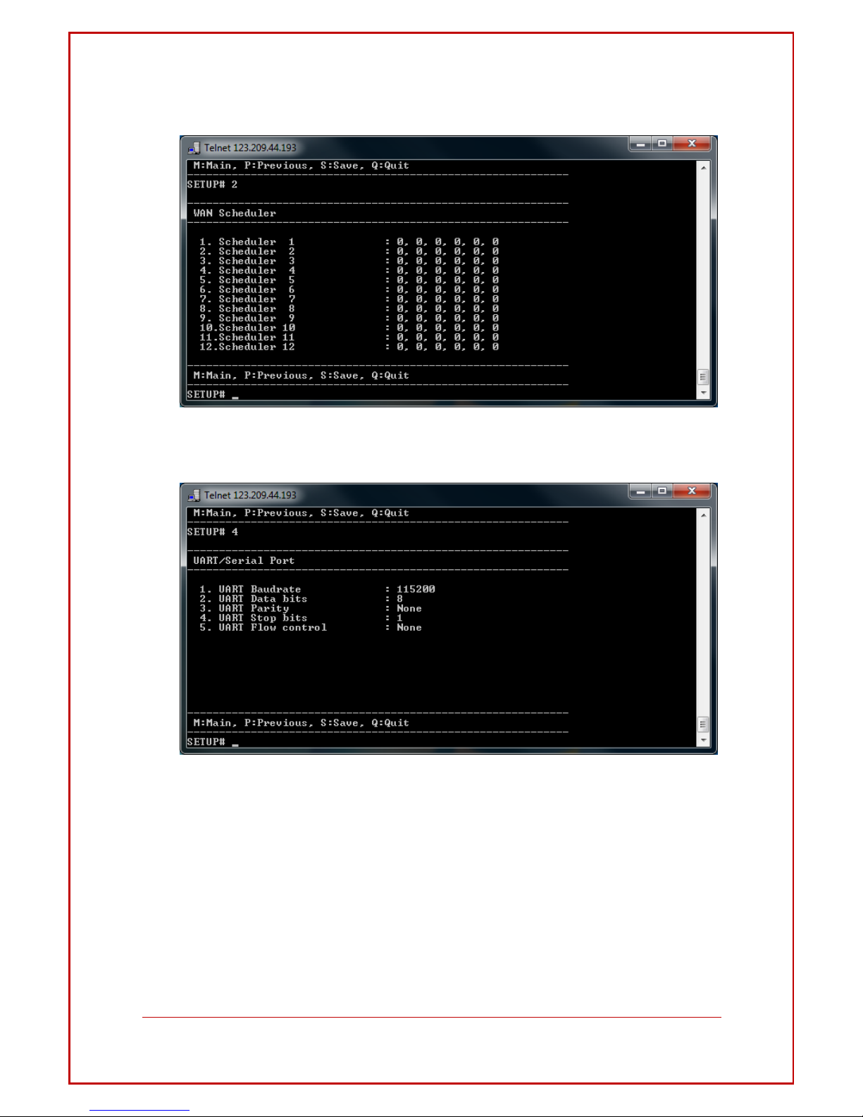
Intelimax+4G User Manual
- 69 -
WAN Scheduler
UART/Serial Port
Page 70

Intelimax+4G User Manual
- 70 -
IPSTACK
SNMP
Page 71

Intelimax+4G User Manual
- 71 -
General
Trap
Page 72
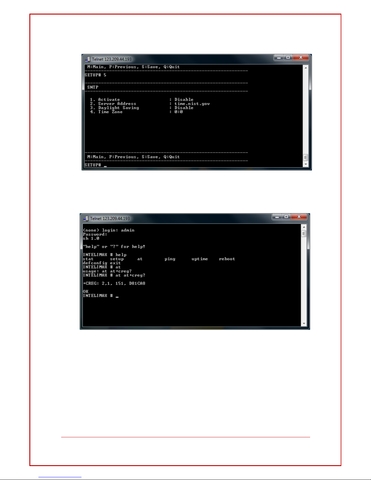
Intelimax+4G User Manual
- 72 -
SNTP
AT command direct to Module
Page 73

Intelimax+4G User Manual
- 73 -
Signal Strength Check
To check signal strength use “at at+csq?” command. Refer to the screen shot
below:
PING command
Page 74

Intelimax+4G User Manual
- 74 -
System uptime check.
The command uptime shows you the connection time as shown in the screen shot
below.
Set to Factory Default
Use defconfig to clear all the setting which will configure the modem to factory
default state.
Page 75

Intelimax+4G User Manual
- 75 -
Reset the INTELIMAX+
Intelimax+ can be power rebooted using the reboot command after logging into
the Intelimax+ remotely
Page 76

Intelimax+4G User Manual
- 76 -
EXTE N D E D /I N TELI M AX + SPECIFI C AT
COMMAND SET (IP STACK MODES)
Device Information
ATI
Manufacturer: Maxon Australia Pty
Ltd Model Number: MA-2020
Product Name: Intelimax+
F/W Revision: 0.0.0 [201201130929]
H/W Version: 1.0
Module F/W Revision:
11.810.09.05.00 LAI: 50506
LAC: 4eeb
CellID:
00cb63b3
IMEI:
354283040117446 OK
AT+CGMI
Maxon Australia Pty Ltd
AT+CGMR – Firmware version
+CGMR: 2.0.8 [201409230653]
AT+CGSN – IMEI number
354283049080793
AT Command Password Protection
This AT command process will protect the changing or monitoring of any AT command
unless the interface password is entered first. Once enabled, any AT command will return
an ERROR response.
AT$$SERIALPWD=<0,1>,<PWD> - disable, enable and set password
Once the command has been entered, a save (AT&W) and reboot (AT$$RESET) is
required. To disable the password protection for a session, enter the following, this will
persist until the modem reboots:
AT$$PWD=<PWD>
WAN Extension Functions
Page 77

Intelimax+4G User Manual
- 77 -
AT$$WANSE?
$$WANSE:
PINGCHECK:Enable,0,0,0.0.0.0,
BACKOFF:Disable,0,0,0,0
OK
Parameters
$$WANSE: X,X,X,X,X,X
0,1 PINGCHECK,BACKOFF
0,1 Disable/Enable both expansion PINGCHECK and BACKOFF
1~60 PINGCHECK Interval (seconds) / 40~59 Seconds of 1st retrial interval of BACKOFF
1~60 PINGCHECK Fail count / 2~10 Minutes of 1st retrial duration of BACKOFF
IP address of 1st server for PINGCHECK / 10~59 Minutes of 2nd retrial interval of BACKOFF
IP address of 2nd server for PINGCHECK / 2~10 Hours of 2nd retrial duration of BACKOFF
OK
WAN Authentication
AT$$WANSA?
$$WANSA: 1,telstra.extranet,0,,,*99#,0,,0,0,0,0,00:00,0
OK
Parameters
$$WANSA: X,X,X,X,X,X,X,X,X,X,X,X,X,X,X,X
1,2 IPStack Auto/Manual
Access Point Domain Name
0,1,2 NONE/PAP/CHAP
Username
Password
Dialup number
0,1 Auto PIN Disable/Enable
PIN code
0 ~ 28 Hours of Periodic reset
0,1 Disable/Enable Reset (TCP Server Listening) – Server – If enabled will wait until client
drops connection
0,1 Disable/Enable Reset (TCP Connected State) – Client – If enabled will wait until
Intelimax+ client drops connection to a server or server drops connection
0,1 Disable/Enable Reset (At scheduled Time) HH:MM
for Reset (At scheduled Time, 24 hour format)
Page 78

Intelimax+4G User Manual
- 78 -
Battery Level for Module Deregistration (12.3 volts ON, 11.9 volts OFF)
0,1~20 LCP Echo Interval (seconds)
0,1~10 LCP Echo Failure (counts)
OK
Note: The Dialup Number cannot be left blank.
Periodic reset
AT$$RESET=24 (setting between 1 and 28 hours)
$$RESET: 24
OK
Parameters
$$RESET: X
0 ~ 24 Hours of Periodic reset
WAN scheduler
AT$$WANSS?
$$WANSS: 0,Disabled
OK
Parameters
$$WANSS:
0,1 RS232 line driver power down
0,1,2 Disable/Day of Week/Duration
0,1 Delete/Add schedule/5~59 Minutes of power up
0~28 Entry number of day of week/0,1, 2,3,4,5,6 Day of week/5~59 Minutes of power
cycle
0~23 Hours of start
0~59 Minutes of start
0~23 Hours of finish
0~59 Minutes of finish
0,1 Engine power down
OK
IP Stack settings
AT$$WANSI?
Page 79

Intelimax+4G User Manual
- 79 -
$$WANSI: 1,1,1,0,0.0.0.0,0.0.0.0,30000,1,300,20,0,0
OK
Parameters
$$WANSI: X,X,X,X,X,X,X,X,X,X,X,X
0, 1,2 None/Server/Client
0,1 Disable/Enable Notify Boot Message
0,1 Disable/Enable Notify IPStack Message
0,1 TCP/UDP
xxx.xxx.xxx.xxx Primary IPAddress
xxx.xxx.xxx.xxx Secondary IPAddress
0 ~ 65535 Port Number
0,1 Disable/Enable Keep Alive
1 ~ 3600 Seconds Keep Alive Interval
5 ~ 60 Seconds Network Dormant Period UDP
0,1 Disable/Enable UDP Keep Alive
0,1,2 ~ 60 Disable/Handshake/Seconds UDP Wake Up
OK
SNMP settings
AT$$SNMPS?
$$SNMPS:
Disable,public,private,DHAGENT,support@maxon.com.au,AUS,192.168.0.200,192.168.0.2
01,192.168.0.202
OK
Parameters
$$SNMPS: X,X,X,X,X,X,X,X,X
0,1 Disable/Enable
Read community
Write community
Name
Contact
Location
Trap 1 IP address
Trap 2 IP address
Trap 3 IP address
OK
Page 80

Intelimax+4G User Manual
- 80 -
DDNS
AT$$DDNSS?
$$DDNSS: Disable,,,
OK
Parameters
$$DDNSS: X,X,X,X
0,1, 2, 3 Disable/DynDNS/MsDNS/Custom DNS
DomainName
UserName
Password
Service Provider
OK
System Settings
AT$$SYSTS?
$$SYSTS:
admin,admin,Enable,23,Enable,Disable,192.168.0.50,Disable,+61427933242,+6142793324
2,+61427933242
OK
Parameters
$$SYSTS: X,X,X,X,X,X,X,X,X,X,X
UserName
Password
0,1 Telnet Disable/Enable
Telnet Port Number
0,1 Syslog Disable/Enable
0,1 Remote syslog Disable/Enable
Remote syslog server address
0,1 SSH Disable/Enable
Phone number of Administrator
Phone number of Administrator
Phone number of Administrator
OK
Page 81

Intelimax+4G User Manual
- 81 -
maXconnect
To enable maXconnect on the Intelimax+ either use the GUI or enter the following
commands when the modem is in IP Stack Auto mode.
$$MAXCNT: 0,120,portal.maxconnect.com.au,1883,updates.maxconnect.com.au
OK
AT$$MAXCNT=?
$$MAXCNT: X,X,X,X,X
0,1 Disable/Enable
Refresh Interval
Broker URL
Broker Port
FTP update server URL
OK
Serial Port settings
Serial port settings including number of data bits, parity, and stop bits must be set using
this command, but other commands can also be set using standard AT commands
such as AT+IPR, AT+IFC etc.
AT$$SPORT?
$$SPORT: 115200,8,N,1,None,0,0
OK
Parameters
$$SPORT: X,X,X,X,X,X,X
1200,2400,4800,9600,19200,38400,57600,115200 Baud rate
7,8 Data bits
N,E,O None/Even/Odd
1,2 Stop bits
None, Software, Hardware Flow control
0 Don’t Care
0,1,2 RS232, RS485FullDuplex, RS485HalfDuplex
OK
Cellular Band selection
Page 82

Intelimax+4G User Manual
- 82 -
AT$$BAND?
$$BAND: 40000000
OK
Parameters
$$BAND:
40: UMTS I 2100
400: UMTS V 850
1000: UMTS VIII 900
10000: LTE I 2100
10000: LTE III 1800
20000: LTE VII 2600
40000: LTE VIII 900
100000: LTE V 850
200000: LTE XXVIII 700
40000000: AUTO
OK
Examples:
To set UMTS 850/2100, LTE 700/1800:
AT$$BAND=210440
$$BAND: 00210440 OK
AT&W
OK
AT$$RESET OK
Check Cellular WAN IP address
AT$$WAN
$$WAN: IP,X
OK
IP: the WAN IP address acquired from Cellular Network. If no WAN connection, it will
return “No PPP”.
A number will appear after the IP address if DDNS is enabled, and a none zero value will
indicate a successful DDNS registration.
FTP Client
To use FTP on the Intelimax+ allow for append on the FTP server. Also restrict the welcome
Page 83

Intelimax+4G User Manual
- 83 -
message to less than 10 characters. Please save and apply settings before using.
AT$$FTPCS?
AT$$FTPCS: 1,192.168.10.1:21,maxon,maxon,0,INTELIMAX+,1000,1
OK
Parameters
$$FTPCS: X,X,X,X,X,X,X,X
0 - Disable
1 - Manual
2 - Hourly (0 - 24)
3 - Time of day (0 - 24)
4 - Day of month (1 - 31 days)
5 – Minutes (0 - 60)
• Host IP/Domain address with Port
• User name
• Password
• Time interval
• Header of file name (limit 10 bytes/characters)
• Size of file (Bytes) – maximum 102,400 bytes, maximum internal buffer size 10MB
• A new file will be created each time the file size is exceeded.
• Time stamp – enable (1) or disable (0) timestamp prefix (in seconds)
A reboot is required when enabling, disabling or making changes to the FTP options.
Examples:
AT command to upload every 1 hour.
AT$$FTPCS=2,20.19.62.23:21,maxon,maxon,1,FILEHEADER,10000,0
AT command to upload every 30 minutes.
AT$$FTPCS=5, 20.19.62.23:21,maxon,maxon,30,FILEHEADER,10000,0
AT command to upload every day at 8PM.
AT$$FTPCS=3, 20.19.62.23:21,maxon,maxon,20,FILEHEADER,10000,0
AT command to upload every 15
th
day of the month.
AT$$FTPCS=4, 20.19.62.23:21,maxon,maxon,15,FILEHEADER,10000,0
1. In the example above file size is 10000 bytes.
2. The modem would create a text file using name specified above (in
the example I have used “fileheader” as the filename)
3. The last setting 0 or 1 decides if the data is time stamped. 0 will only log data
Page 84

Intelimax+4G User Manual
- 84 -
in the text file. 1 will stamp all data logged with date and time.
The "size of file" parameter is used for limiting the file size of the csv file. All the input from
serial port will be saved in the .csv file, and once the file size of that csv file exceed the
size limit, another file will be created to hold the input. The value allowed is 1000 -
100*1000 Bytes.
Based on the configuration, the file could be uploaded to server periodically. For
example,
AT$$FTPCS=5,192.168.10.50:21, maxon, maxon, 30,FILEHEADER,10000,0
with this setting, the modem will send out .csv file to FTP server every 30 minutes. If the
input has not exceeded limit 10K bytes (in this case), modem will send this file only, then
generate another file for holding future input. If the input is more than 10K bytes, there
should be more than one file generated, each file should not exceed 10K bytes, all these
files will be sent to FTP server when time comes.
File uploaded with date time stamp disabled.
AT$$FTPCS=2,20.19.62.23:21,maxon,maxon,1,FILEHEADER,10000,0
AT+CSQ
AT+CSQ
AT+CSQ
AT+CSQ
AT+CSQ
AT+CSQ
File uploaded with date time stamp enabled.
AT$$FTPCS=2,20.19.62.23:21,maxon,maxon,1,FILEHEADER,10000,1
09/11/2012 15:44:05 AT+CSQ
09/11/2012 15:44:06 AT+CSQ
09/11/2012 15:44:07 AT+CSQ
09/11/2012 15:44:08 AT+CSQ
09/11/2012 15:44:09 AT+CSQ
AT$$FTPFL
Displays the files waiting to be uploaded
Page 85

Intelimax+4G User Manual
- 85 -
AT$$FTPSC
OK
Will start the FTP connection and upload the files. Can be used to force an upload
When in periodic mode. If no WAN connection is currently established (such as in IP Stack
Manual mode) the Intelimax+ will establish the PPP and socket connections, upload the
FTP files then drop the socket and PPP connections.
Signal Strength
AT+CSQ?
+CSQ: 25,99
OK
Open PPP connection
AT$$IPCTOP
Close PPP connection
AT$$IPCTCP
Open TCP/UDP Socket
AT$$IPCTOS
Close TCP/UDP Socket
AT$$IPCTCS
Change Remote Server IP address
AT$$IPCTRIP=0,ip,ad,dr,ess,<port>
Eg. AT$$IPCTRIP=0,123,456,789,01,30000
Change client/server mode
AT$$IPCFL=4,<0,1> where 0 for server, 1 for client
Eg. AT$$IPCFL=4,0 sets modem to server mode
IPStack Connection Settings
AT$$IPSCFG?
Page 86

Intelimax+4G User Manual
- 86 -
$$IPSCFG: 30,100,300
OK
AT$$IPSCFG=?
$$IPSCFG: X,X,X
IPSTACK SEND DELAY: 1 ~ 2000 msec IPSTACK
BUFFER SIZE: 32 ~ 1450 bytes IPSTACK SOCKET
TIMEOUT: <0,10~3600> sec PPP DISCONNECT
TIMEOUT: <0,30~3600> sec OK
AT$$IPSCFG=30,100,200,301
OK
AT$$IPSCFG?
$$IPSCFG: 30,100,200,301
OK
Retry Settings
AT$$RETRYTO=<item>,<num>
item: 1 – TCP Client
2 – WAN
num: Number of retries, ranges 2 ~ 100
AT$$RETRYTO?
$$RETRYTO:
1,10
2,10
OK
Change modem mode
AT$$CHGMODE=
1 – IP Stack Auto
2 – IP Stack Manual
3 – Serial Modem
at$$chgmode=1 OK
Save and Reboot
AT$$RESET
At$$reset
OK
Page 87

Intelimax+4G User Manual
- 87 -
Factory Reset
AT$$FACTORY
OK
Profile Save
AT$$PFSET
Save the modem’s profile default settings
Profile Set
AT$$PFRST
Reset to the modem to use the profile default
AT over IP on IPStack
Only 12521 can be used for AT over IP.
AT$$OVERIP=?
$$OVERIP: X,X,X
0,1 Disable/Enable
Listen Port Number
Session Timeout (0 ~ 3600 seconds).
OK
at$$overip?
$$OVERIP: 1,12521,120
OK
at$$overip=0
Require Save and System Reboot
OK
at$$overip?
$$OVERIP: 0,12521,120
OK
at$$overip=1,12521
Require Save and System Reboot
OK
at$$overip?
$$OVERIP: 1,12521,120
OK
Page 88

Intelimax+4G User Manual
- 88 -
Modem Emulation
The Intelimax+ modem emulation can be configured using the following AT commands:
To enable modem emulation and add a data number to IP address and port number
emulation to the list
at$$emul=1,phone_number,IP_address,port_number
e.g. at$$emul=1,01044204414,10.0.0.1,5000
To check current emulation list (must have already enabled emulation)
at$$emul?
$$EMUL: 1,3
0,01044204412,192.168.101.2,3000
1,01044204411,192.168.101.2,30001
2,01044204414,10.0.0.1,5000
OK
To Enable/Disable Modem Emulation – this must be enabled on the server Intelimax+ for
CONNECT message
at$$emul=0,0 – disable
at$$emul=0,1 - enable
To delete a rule from the list
at$$emul=2,list_number
e.g. at$$emul=2,1
OK
at$$emul?
$$EMUL: 1,2
0,01044204412,192.168.101.2,3000
1,01044204414,211.232.22.1,500001
OK
It is recommended to add a TCP delay to the client connect message to account for
the incoming RING messages on the server side. These server RING messages take 2
seconds to complete. This can be achieved using the AT$$TCPDEL=2000 command.
It is also recommended to turn off the IP Stack notification messages as these may
confuse the client or server, this can be achieved using the AT$$WANSI command.
Page 89

Intelimax+4G User Manual
- 89 -
SMS on Boot
The Intelimax+ can be configured to send an SMS at boot time using the following AT
commands:
at$$pwronsms
at$$pwronsms=?
$$PWRONSMS=1,0/1 enable/disable
$$PWRONSMS=2,1/2/3,Phone Number up to 3 phone numbers
$$PWRONSMS=3,Message
Prepare modem for hard shutdown
This function is highly recommended when using the modem with an external,
controlled power supply. If the modem is going to have its power dropped regularly this
AT command allows for the processor to perform housekeeping duties to ensure that
the shutdown process does not damage the modem or internal cellular module. Wait
for at least 4 seconds after issuing the command before dropping power to the modem.
AT$$RTD
OK
Modmax Compatibility Mode
AT$$SPC
This changes the IP Stack responses from Intelimax+ style responses to Modmax style
responses.
ntelimax+ Mode (Mode 0)
Modmax Mode (Mode 1)
$$TCP_Connect_To: 125.181.12.34
[01/24/2014 08:00:36]
[18:57:55 28 JAN 2014]
$$TCP_Connect_To: 192.168.10.50
[01/24/2014 08:05:36]
[Connection_Close_By_Timed_Out]
[08:31:12 24 JAN 2014] TCP connection
disconnected
AT$$SPC?
$$SPC: <mode>
OK
<mode>:
0: mode 0 (Default)
1: mode 1
2: mode 2
Page 90

Intelimax+4G User Manual
- 90 -
AT$$SPC=<passcode>
$$SPC: <mode>
OK
<passcode>:
857653: mode 0
356758: mode 1
AT$$TCPDEL
Some older systems working with the Modmax cannot handle the speed between
messages, this delay allows for these legacy systems to handle this delay.
AT$$TCPDEL=?
$$TCPDEL: X
Delay between try and connect range from 200 to 1000 mili-seconds. OK
AT$$TCPDEL=200
O
K
AT$$TCPDEL?
$$TCPDEL: 200
OK
Page 91

Intelimax+4G User Manual
- 91 -
EXTE N D E D /MODEM SPECIFI C AT CO M M A N D
SET (IP and S ERIA L MO DES)
Save settings and reset/restart modem
AT&W (Serial and IP Stack modes)
Saves AT command settings
AT%RESET=1 (Serial Modem mode only)
AT$$RESET (Serial and IP Stack modes)
Applies saved AT commands with a reboot
Standard AT Commands for serial interface
Note.1 : [ ] indicates default value.
Note.2 : &D option only valid when Serial Port is using no flow control. DTR signal will be
used together with CTS/RTS as Hardware Flow Control signals.
SMS Commands
Parameter
Description
[E0]
Do not echo command set in command state or online command
state.
E1
Echo command set in command state or online command state.
[Q0]
Q1
Return result codes.
Do not return result codes.
[&C0]
DCD line always ON.
&C1
DCD line is ON during a circuit switched call. In IP Stack mode, the
behaviour is the same as &C0.
&C2
DCD line is normally ON and will toggle OFF for 1 second when the
circuit switched call is disconnected. In IP Stack mode, DCD line will be
always OFF.
&C3
DCD line is normally OFF and will be ON when modem has successfully
established a PPP Data (packet switched) call (only applies to IP STACK
mode). In Serial Modem mode, DCD line will be always OFF.
&C4
DCD line is normally OFF and will be ON when modem has successfully
established a PPP Data and opened a socket with remote server (only
applies to IP STACK mode). In Serial Modem mode, DCD line will be
always OFF.
[&D0]
Ignore DTR line signal.
&D1
Enter online command state following ON-to-OFF transition of DTR line
while retaining the data connection.
&D2
Disconnect the data connection following ON-to-OFF transition and
change to command state after back to ON state. In Serial Modem
Mode, during OFF state of the DTR line, the auto-answer function (see
S0) is disabled. During the transition, DTR line has to be in OFF state for
at least one second for the modem to respond.
S0
[2], <1 to 255>
0
Automatic answering. [Enable automatic answering
after (Value) x 6 seconds.]
0: No auto- answering
Page 92

Intelimax+4G User Manual
- 92 -
AT commands for SMS support is slightly different between operational modes. In Serial
Modem Mode, most standard SMS AT commands (Cellular Module dependant) are
supported. Under IP stack modes, only those commonly used commands are currently
supported: AT+CMGF, AT+CMGS, AT+CMGL, AT+CMGR, and AT+CMGD.
Single AT command SMS AT+MMC SMSMO
AT+MMC SMSMO <Phone number> <message><CR>
Eg. AT+MMC SMSMO 0400123456 Boiler Temperature Too High!<CR>
Maximum length of message is 160 characters.
Some characters are not supported: \, [, ], ^, ~, `
Prepare modem for hard shutdown
This function is highly recommended when using the modem with an external,
controlled power supply. If the modem is going to have its power dropped regularly this
AT command allows for the processor to perform housekeeping duties to ensure that
the shutdown process does not damage the modem or internal cellular module.
AT$$RTD
OK
SMS on Boot
The Intelimax+ can be configured to send an SMS at boot time using the following AT
commands:
at$$pwronsms
at$$pwronsms=?
$$PWRONSMS=1,0/1 enable/disable
$$PWRONSMS=2,1/2/3,Phone Number up to 3 phone numbers
$$PWRONSMS=3,Message
Tripple Plus (+++) Control using AT$$TPSW
The Intelimax supports two different methods for +++ control when in serial modem
mode. If the connection to or from the modem is over CSD then it is recommended
that the AT$$TPSW=0 is configured so that the internal module controls triple-plus
switching. If the connection from the modem is a PPP dial out connection (e.g.
ATDT*99***1#) then it is recommended that the +++ control is handled by the separate
Page 93

Intelimax+4G User Manual
- 93 -
CPU, in which case AT$$TPSW=1 should be configured. After each configuration save
and reboot using AT&W and AT$$RESET.
AT$$TPSW=0 – Triple-plus switching handled by internal module
AT$$TPSW=1 – Triple-plus switching handled by the modem
Serial Port Settings
The follow AT commands are supported in both IP and Serial Modem modes to change
the serial baud rate and flow control:
Baud Rate: AT+IPR
AT+IPR=9600
OK
Flow Control: AT+IFC
AT+IFC=0,0 - no flow control
OK
AT+IFC=2,2 - hardware flow control
OK
CSD and PSD/PPP dial out commands (Serial mode only)
Command
TE2
MT2
Command
TE2
MT2
ATD<phone_number>
Notify
TE2
MT2
CONNECT (Data call connected)
Connect <Speed> if
connect_baud is set. NO CARRIER
(Data call failure)
Value
phone_number:
for Packet Switched Data: *99# (Australia – requires authentication)
for Circuit Switched Data: You will need a data number ( Code 2620
activated on the SIM account)
Notify
TE2
MT2
AT: RING
Command
TE2
MT2
ATA (answer data call)
Notify
TE2
MT2
CONNECT (Data call connected)
CONNECT <SPEED> if connect_baud is
enabled. NO CARRIER (Data call failure)
Call State
Command
TE2
MT2
+++ (escape command to go to off-line
command state) ATH (release call)
Notify
TE2
MT2
NO CARRIER
Page 94

Intelimax+4G User Manual
- 94 -
Periodic Reset (Serial mode only)
at$$preset=2
OK
at$$preset?
$$PRESET: 2
OK
To configure periodic reset in IP Stack modes, use the AT$$RESET command
Auto Recovery from CSD/PPP Call (Serial mode only)
The command will set up a time delay for the modem to perform a reboot if there is no
CSD/PPP call is made after the previous call or modem boot up.
The configurable time delay is 1 to 24 hours. If “0” is set, the auto recover will be
disabled.
If auto recover is enabled and there is an incoming CSD call, the modem will perform a
reboot in 20 minutes (non-configurable) if there is no active CSD/PPP Calls.
at$$autocover=2
OK
At$$autorecover?
$$AUTORECOVER: 2
OK
Getting S0 value (Serial mode only)
Please use ATS0? Command to get the S0 value. AT&V command will give you an
incorrect S0 Value:
ATS0=2
OK
ATS0?
2
OK
 Loading...