

Page 1
M-99-49
REV. K
OCTOBER 2005
© MAXON Lift Corp. 2005
Page 2

TABLE OF CONTENTS
WARNINGS ......................................................................................................................... 3
ST ANDARD LIFTGA TE COMPONENTS .............................................................................. 4
GPT-SERIES INST ALLA TION P ARTS BAGS........................................................................ 5
STEP 1 - PREPARE VEHICLE............................................................................................. 6
STEP 2 - WELD EXTENSION PLA TE TO VEHICLE............................................................. 8
STEP 3 - WELD LIFTGA TE T O VEHICLE .......................................................................... 10
STEP 4 - RUN POWER CABLE ......................................................................................... 14
STEP 5 - CONNECT POWER CABLE ............................................................................... 15
STEP 6 - INST ALL CONTROL SWITCH .............................................................................. 16
STEP 7 - CONNECT POWER CABLE T O BA TTERY......................................................... 19
STEP 8 - REMOVE LOCKING ANGLES & WELDS ........................................................... 20
STEP 9 - WELD PLA TFORM OPENER TO LIFTGA TE....................................................... 21
STEP 10 - FINISH WELDING LIFTGA TE TO VEHICLE....................................................... 24
STEP 11 - INSTALL & ADJUST SADDLES ........................................................................ 25
STEP 12 - CHECK HYDRAULIC FLUID ............................................................................. 26
STEP 13 - WELD HOOK AND EYE TO LIFTGA TE ............................................................. 27
STEP 14 - WELD DOCK BUMPERS TO LIFTGATE........................................................... 28
STEP 15 - BOL T RUBBER BUMPERS TO LIFTGA TE........................................................ 29
STEP 16 - PLACE DECALS .............................................................................................. 30
STEP 17 - VEHICLE T AILLIGHT POSITIONING .................................................................. 32
HYDRAULIC SYSTEM SCHEMATIC ................................................................................ 33
ELECTRICAL SYSTEM SCHEMATIC .............................................................................. 34
OPTIONS ........................................................................................................................... 35
OPTIONAL LIFTGA TE COMPONENTS............................................................................... 35
RECOMMENDED LIFTGA TE POWER CONFIGURA TION ................................................. 36
Page 3

Comply with the following WARNINGS while installing Liftgates. See Operation Manual
M-97-16 for operating safety requirements.
!
WARNINGS
• Read and understand the instructions in this Installation Manual before installing Liftgate.
• Before operating the Liftgate, read and understand the operating instructions in Operation Manual
M-97-16.
• Comply with all WARNING and instruction decals attached to the Liftgate.
• Keep decals clean and legible. If decals are defaced or missing, replace them. Free replacement
decals are available from Maxon Customer Service.
• Consider the safety and location of bystanders and location of nearby objects when operating the
Liftgate. St and to one side of the platform while operating the Lif tgate
• Do not allow untrained persons to operate the Liftgate.
• Do not stand under, or allow obstructions under the platform when lowering the Liftgate. Be sure
your feet are clear of the Liftgate.
• Keep fingers, hands, arms, legs, and feet clear of moving Liftgate parts (and platform
edges) when operating the Liftgate.
• Correctly stow platform when not in use. Extended platforms could create a hazard for
people and vehicles passing by.
• Make sure vehicle battery power is disconnected while installing Liftgate. Connect vehicle
battery power to the Liftgate only when installation is complete or as required in the installation
instructions.
• Wear appropriate safety equipment such as protective eyeglasses, faceshield and clothing while
performing maintenance on the Liftgate and handling the battery. Debris from drilling and contact
with battery acid may injure unprotected eyes and skin.
• Be careful working by an automotive type battery . Make sure the work area is well ventilated and
there are no flames or sparks near the battery. Never lay objects on the battery that can short the
terminals together. If battery acid get s in your eyes, immediately seek first aid. If acid gets on your
skin, immediately wash it off with soap and water .
• If an emergency situation arises (vehicle or Liftgate) while operating the Liftgate, release the control
Toggle Switch and the Liftgate will stop.
• A correctly installed Liftgate operates smoothly and reasonably quiet. The only noticeable noise
during operation comes from the pump unit while the platform is raised and lowered. Listen for
scraping, grating and binding noises and correct the problem before continuing to operate Liftgate.
• If it is necessary to stand on the platform while operating the Liftgate, keep your feet and any
objects clear of the inboard edge of the platform. Your feet or objects on the plat form could be
trapped between the platform and the Liftgate extension plate.
• Never perform unauthorized modifications on the Liftgate. Modifications may result in early failure of
the Liftgate and may create hazards for Liftgate operators and maintainers.
11921 Slauson Ave. Santa Fe Springs, CA. 90670 (800) 227-4116 FAX (888) 771-7713
3
Page 4
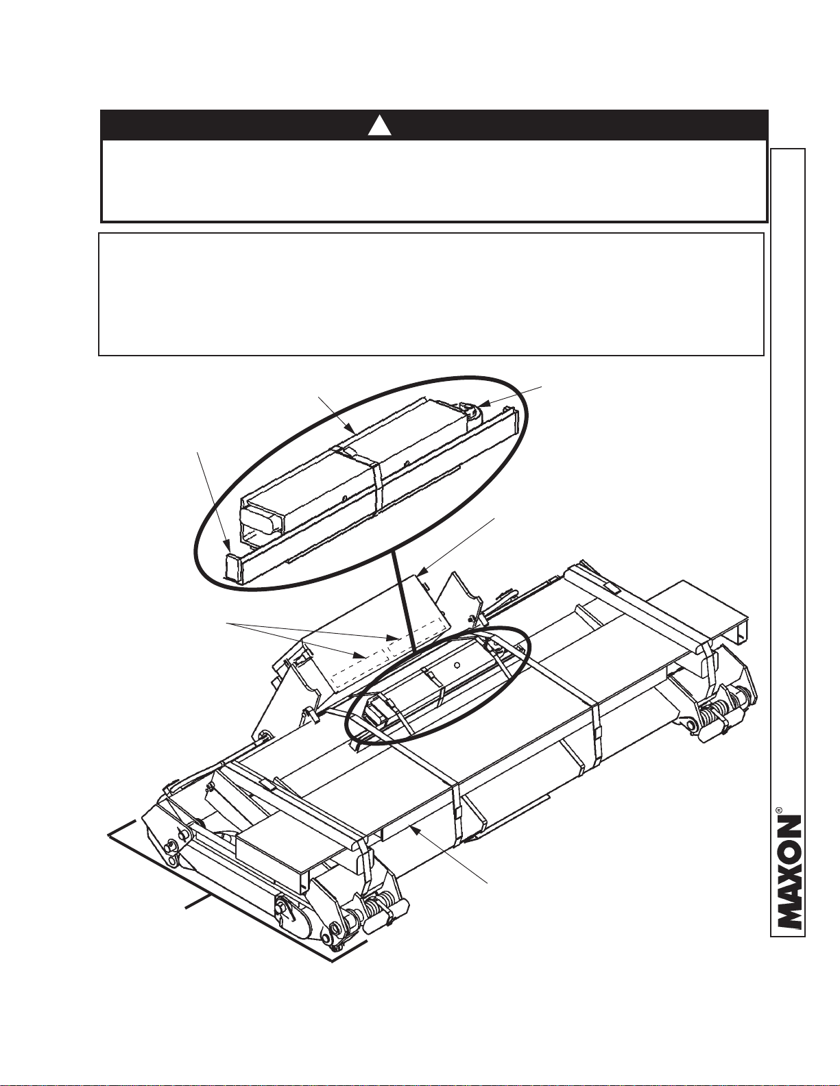
STANDARD LIFTGATE COMPONENTS
!
CAUTION
Prevent injuries and equipment damage. Before cutting the shipping straps from
the Liftgate, put Liftgate on level ground that will support at least 1500 pounds. Be
careful lifting and moving components (such as Extension Plate) after shipping
straps are removed.
NOTE: Make sure you have all components and parts before you start installing Liftgate.
Compare parts in the Part Box and each Kit Box with packing list enclosed in each
box. If parts and components are missingor incorrect call:
Maxon Customer Service
Call (800) 227-4116 or
Send e-mail to customersupport@maxonlift.com
DOCK BUMPER
BRACES
P ARTS BAGS
(SEE TABLE 5-1)
OPENER ASSEMBL Y
ANGLES
PUMP BOX
(SEE T ABLE 5-1)
MAIN
ASSEMBL Y
11921 Slauson Ave. Santa Fe Springs, CA. 90670 (800) 227-4116 FAX (888) 771-7713
EXTENSION
PLATE
TYPICAL LIFTGATE PACKAGED FOR SHIPMENT
FIG. 4-1
4
Page 5

GPT-SERIES INSTALLATION PARTS BAGS
STNETNOCXOBSTRAP.YTQREBMUNTRAP
.1"8/1X"1X"2/1-2,TALF2999102
.2REPMUBKCODREBBUR,TIK1014302
.3)AG2#(GULREPPOC1877622
F1224462
.4.GL'83,PMA002,ELBACREWOPDESU
.5"2/1-1X"4/3,DAPDEGROFPORD,EYE1839622
.6.GL"2/1-1X.D.I"8/5,GNIBUTKNIRHSTAEH140-613352
.7YSSAKOOH1007722
.8Y
.9"4/1X"4/3-1X"2/1-3,MIHS2137462
.01"61/1X"1X"2/1-2,MIHS2237462
.11"8/3X"4X"5,TALF2592922
.21TIKSLAUNAM&LACED1-
RAW.D187-87-M
SLACED.F-
.31MOOLREBBUR01#,PMALC2186108
.41"1X42-01WERCSGNIPPAT-FLES45-750009
.51"8/3-1X"2/1,PILCEMARF7970050
SSAHCTIWSDEDLOM110-159462
LAUNAMNOITAREPO.A161-79-M
LAUNAMNOITALLATSNI.B194-99-M
LAUNAMECNANETNIAM.C151-79-M
DRACYTNAR
MROFYEVRUSREMOTSUC.E140-49-M
SEGAPLACEDOTREFER
.LAUNAMSIHTNI
.61ELIFORPWOL,ELDDAS210-948562
.7131-"2/1,DE
.818EDARG,GL"4/1-2,31-"2/1,EMARF,TLOBXEH43-420109
GNALF,TUNKCOL4320109
TABLE 5-1
5
11921 Slauson Ave. Santa Fe Springs, CA. 90670 (800) 227-4116 FAX (888) 771-7713
Page 6

STEP 1 - PREPARE VEHICLE
NOTE: BODY Maximum and Minimum Operating Bed Height:
For GPT-25, GPT-3, GPT-4, & GPT -5 With St andard Plat form -
Maximum height is 55” (Unloaded). Minimum height is 46” (Loaded).
On Vehicle Bodies equipped with swing open doors, the Extension Plate
and Vehicle Body must be modified to inst all this Liftgate.
NOTE: Make sure vehicle is parked on level ground while preparing V ehicle and installing
Liftgate.
1. Check for correct clearances (FIG. 6-1 and FIG. 6-2) on vehicle to prevent interference
between vehicle and Liftgate.
APPROX. 20”
(REF . ONL Y)
14”
55” MAX. BED HEIGHT
46” MIN. BED HEIGHT
55” MAX. BED HEIGHT
46” MIN. BED HEIGHT
10”-19”
REF .
GPT-25 & GPT-3 CLEARANCES
FIG. 6-1
APPROX. 24”
(REF . ONL Y)
14”
11921 Slauson Ave. Santa Fe Springs, CA. 90670 (800) 227-4116 FAX (888) 771-7713
GPT-4 & GPT-5 CLEARANCES
FIG. 6-2
6
12”-21”
REF.
Page 7
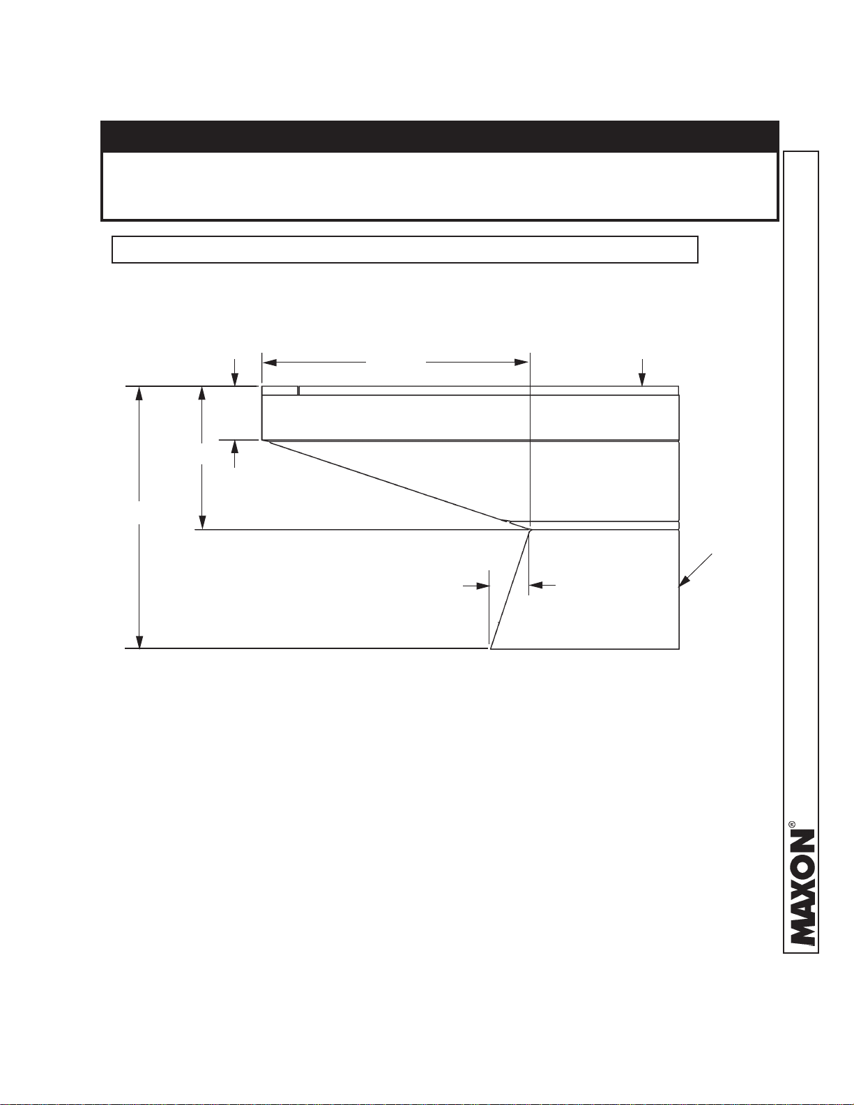
STEP 1 PREPARE VEHICLE - Continued
CAUTION
T o prevent Aluminum Plat form from being damaged, make sure T ruck Frame is cut
correctly as shown in the illustration below. If the Frame is cut incorrectly, Platform
may hit the Truck Frame while stowing Lif tgate.
NOTE: If installing Liftgate on a trailer , skip frame cutting instructions in Item 2.
2. Fit Liftgate to a truck body by cutting the truck frame members as shown in FIG. 7-1.
TOP OF TRUCK
22-1/2”
4-1/2”
12”
BODY FLOOR
20”
TRUCK
FRAME
2-11/16”
CUTS FOR GPT-25, GPT-3, GPT-4 & GPT -5
FIG. 7-1
11921 Slauson Ave. Santa Fe Springs, CA. 90670 (800) 227-4116 FAX (888) 771-7713
7
Page 8
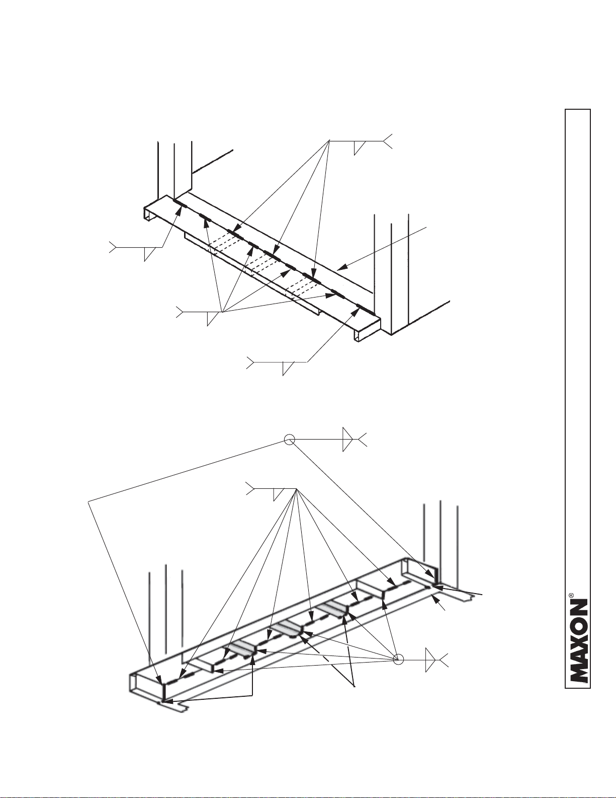
STEP 2 - WELD EXTENSION PLATE TO VEHICLE
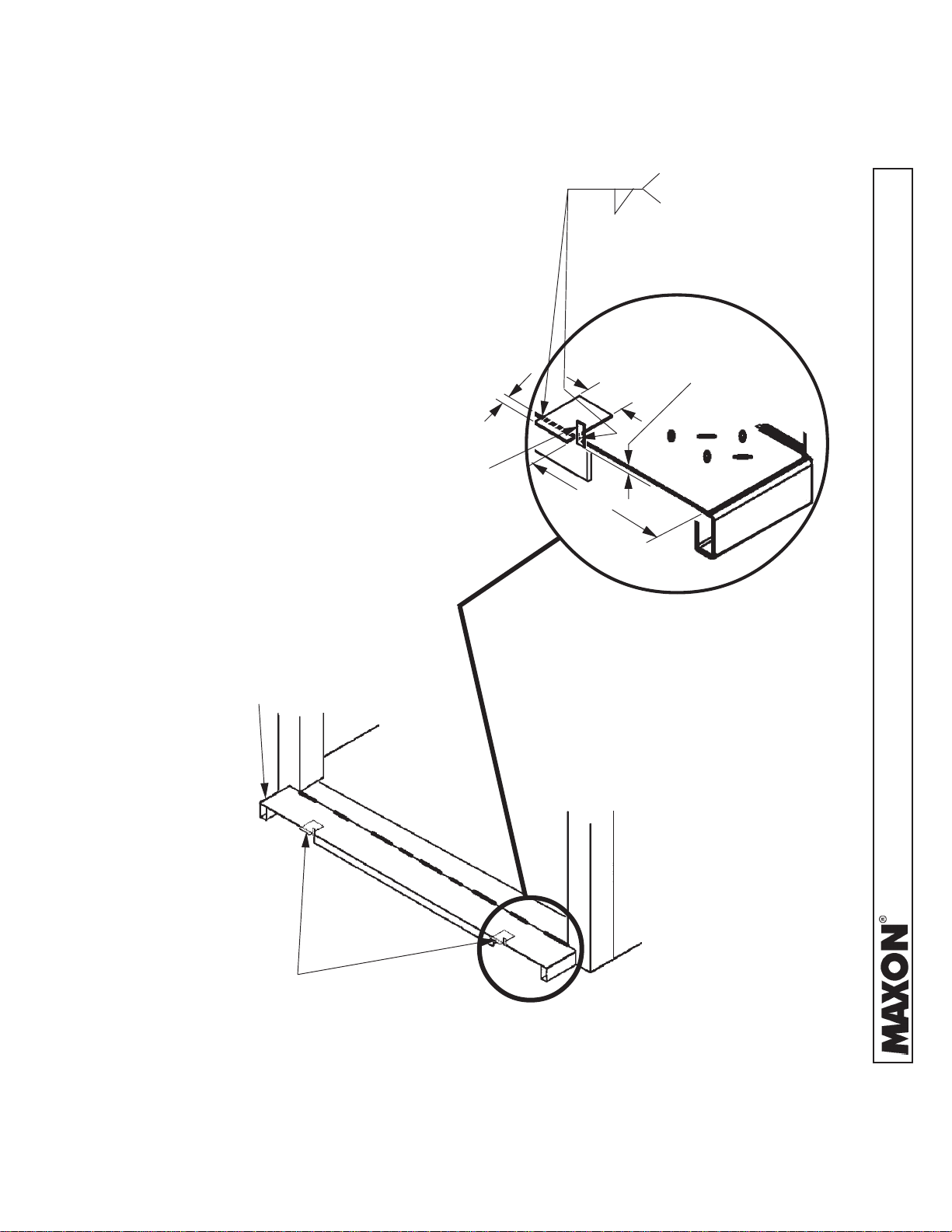
1. Center the Extension Plate on vehicle body . Before welding Extension Plate to vehicle
body , make sure top surface of Extension Plate is flush with floor of vehicle body . Weld the
Extension Plate to vehicle body sill as shown in FIG. 8-1 and FIG. 8-2.
4” LG.
4” WELDS SHOWN
1/4”
2” LG . CENTERED
BETWEEN
4” LG . LOCA TED ABOVE EACH OF
3 RECT ANGULAR TUBES (TUBES
SHOWN SHADED IN FIG . 3)
(P ART OF VEHICLE BODY)
1/4”
4” LG.
1/4”
1/4”
EXTENSION PLATE WELDS - VIEWED FROM ABOVE
FIG. 8-1
SILL
2 PLACES, MAKE 1”
2” LG , 12 PLACES
EQUAL SP ACING
(TYP.)
1/4”
1/4”
1” GAP
GAP WHERE SHOWN
(P ART OF
VEHICLE BODY)
1/4”
1” GAP
SILL
5 PLACES, MAKE 1”
GAP WHERE SHOWN
EXTENSION PLATE WELDS - VIEWED FROM UNDERNEATH
FIG. 8-2
11921 Slauson Ave. Santa Fe Springs, CA. 90670 (800) 227-4116 FAX (888) 771-7713
1” GAP
8
Page 9
STEP 2 - WELD EXTENSION PLATE TO VEHICLE -
Continued
2. Place 2 temporary Support Straps (5” x 4” x 3/8”
flats from Parts Box) on the Extension Plate as
shown in FIG . 9-1A. Also, put 2 temporary
spacers (2” x 1” x 1/8” flats from Parts Box)
between Platform and Extension Plate as shown
in FIG . 9-1B. (Sp acers keep 1/8” between
Platform and Extension Plate while welding
liftgate to vehicle frame.) Weld the S traps and
Spacers to Extension Plate (FIG. 9-1B).
1” (APPROX. - TYP.
STRAP OVERHANG)
1/8” SP ACER
EXTENSION
PLATE
1/4” LG . TACK, SUPPORT
1/4”
4”
17-1/2”
STRAP TO EXTENSION
PLA TE (1 WELD ONL Y),
SP ACER & SUPPORT
STRAP TO EXTENSION
PLA TE (1 WELD ONL Y)
1/2” (APPROX.-
TYP . SP ACER
OVERHANG)
STRAP & SPACER WELDS
(TYPICAL - BOTH ENDS OF
EXTENSION PLATE)
FIG. 9-1B
SUPPORT
STRAPS
11921 Slauson Ave. Santa Fe Springs, CA. 90670 (800) 227-4116 FAX (888) 771-7713
FIG. 9-1A
9
Page 10
STEP 3 - WELD LIFTGATE TO VEHICLE
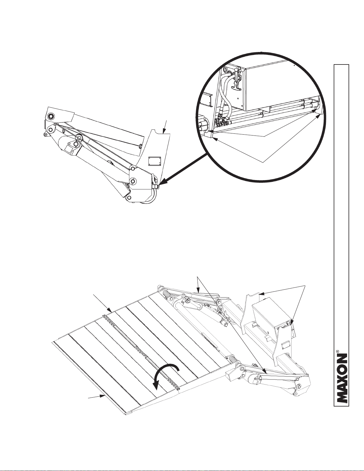
1. Remove Split Looms from Mounting Plates
(FIGS. 10-1A & 10-1B). (S plit Looms will be
reinstalled later after final welding).
MOUNTING
PLA TE
SPLIT LOOMS
MOUNTING PLA TES
FIG. 10-1B
RH SIDE VIEW OF LIFTGATE
FIG. 10-1A
2. Unfold the Platform and Flipover (FIG. 10-2).
LOCKING ANGLES
PLA TFORM
(UNFOLDED)
(REF)
MOUNTING
PLATES
11921 Slauson Ave. Santa Fe Springs, CA. 90670 (800) 227-4116 FAX (888) 771-7713
FLIPOVER
(UNFOLDED)
PLATFORM & FLIPOVER UNFOLDED
FIG. 10-2
10
Page 11
STEP 3 - WELD LIFTGATE TO VEHICLE - Continued
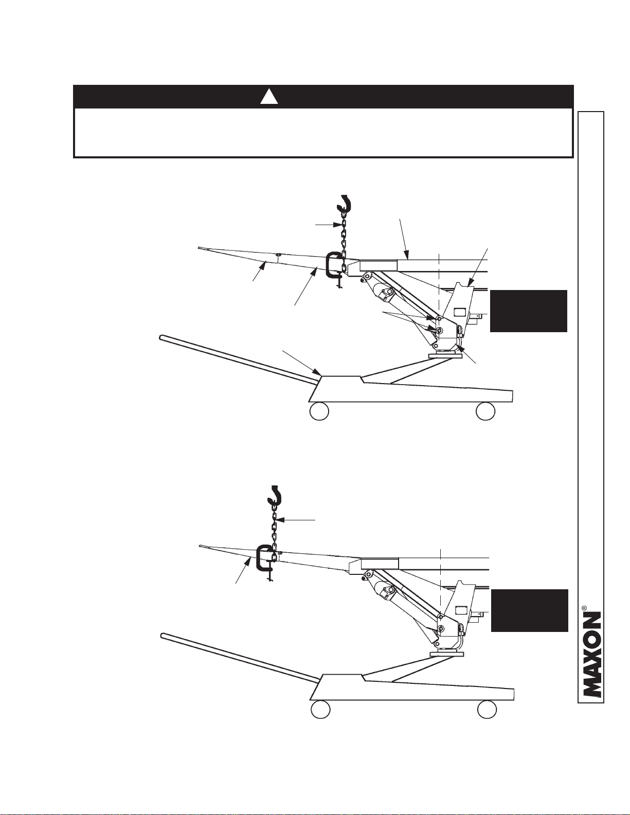
!
CAUTION
T o prevent damage to Aluminum Flip Over, NEVER hoist the Liftgate by the
Flipover as shown in the NO illustration. Hoist the Liftgate by the Platform only as
shown in the YES illustration.
3. Make sure Hoist will not
be set up the incorrect
way (FIG. 1 1-2). Place a
“C”-Clamp on each side
of Platform as shown in
FIG. 11-1. (Clamps
prevent Hoist Chain
from slipping off Platform.) Place chain all
around Platform
(FIG. 11-1).
HOIST CHAIN
FLIPOVER
PLA TFORM
FLOOR JACK
VEHICLE FLOOR
(HORIZONT AL)
PINS
(LINED UPVERTICAL)
MOUNTING
PLATE
YES
4. Hoist the Liftgate. Then place
floor jack under Main Frame
(FIG. 11-1). Jack the Liftgate
in position. Make sure V ehicle
Floor is horizontal and Pins are
lined up (FIG. 11-1).
FLIPOVER
MAIN FRAME
CCORRECT WAY TO HOIST LIFTGATE
FIG. 11-1
HOIST CHAIN
11921 Slauson Ave. Santa Fe Springs, CA. 90670 (800) 227-4116 FAX (888) 771-7713
NO
INCORRECT WAY TO HOIST LIFTGATE
FIG. 11-2
11
Page 12
STEP 3 - WELD LIFTGATE TO VEHICLE - Continued
!
WARNING
Liftgate is shipped from factory with Mounting Plates that are only Tack Welded to
Main Frame. Weld as shown in illustration before operating Liftgate.
CAUTION
Prevent damaged hydraulic hoses. If welding next to hydraulic hoses, use
a protective cover such as a welding blanket to cover the hoses.
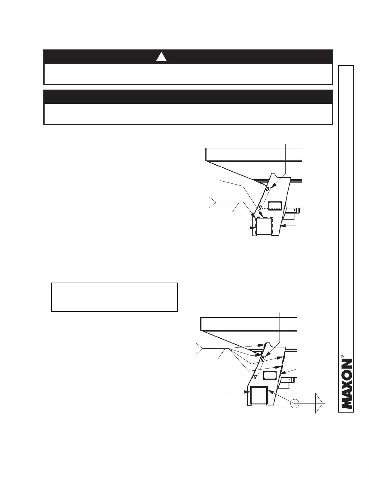
5. Check if both Mounting
Plates line up with the
vehicle frame. If the
Mounting Plates do not
line up, remove the tack
welds from one Mounting
Plate (FIG. 12-1). Make
ORIGINAL T ACK WELDS
(REMOVE TO REPOSITION
MOUNTING PLA TE)
sure Liftgate stays centered on vehicle. Reposition the Mounting Plate
against vehicle frame.
T ack weld as shown in
FIG. 12-1. Repeat for
second Mounting Plate
(reposition and tack
weld).
NOTE: Weld both Mounting Plates to
vehicle frame before welding Mounting
Plates to Main Frame.
T ACK
(TYPICAL - RH & LH
MOUNTING PLA TES)
MAIN FRAME
(CUT-A WA Y VIEW)
REPOSITIONING MOUNTING PLA TE
VEHICLE FRAME CUTOUT
(TYPICAL TRUCK FRAME SHOWN)
5/16”
MOUNTING
PLATE
(RH SIDE SHOWN)
FIG. 12-1
VEHICLE FRAME CUTOUT
(TYPICAL TRUCK FRAME SHOWN)
6. Clamp both Mounting
Plates to vehicle frame.
Before welding, make sure
cutout in vehicle frame
does not block 2 slotted
holes in Mounting Plate
(FIG. 12-2). Weld the
Mounting Plates to
vehicle frame as shown in
FIG. 12-2. Next, weld both
Mounting Plates to Main
Frame (FIG. 12-2).
Remove clamps.
2” LG. 4 PLACES
(TYPICAL - RH & LH
MOUNTING PLA TES)
WELD TO VEHICLE FRAME AND MAIN FRAME
12
5/16”
11921 Slauson Ave. Santa Fe Springs, CA. 90670 (800) 227-4116 FAX (888) 771-7713
MOUNTING
PLATE
MAIN FRAME
(CUT-A WAY VIEW)
5/16”
(RH SIDE SHOWN)
FIG. 12-2
Page 13

STEP 3 - WELD LIFTGATE TO VEHICLE - Continued
7. At the tip of the Flipover , measure
distance Flipover is raised above bed
level. Tip of Flipover should be above
level line shown in FIG. 13-1, and up to
1” maximum (FIG. 13-1). If measurement is correct, Liftgate is mounted
correctly . If measurement is incorrect,
check the measurements used for
preparing vehicle in STEP 1, and
if needed, repeat this entire step
(STEP 3).
TIP OF
FLIPOVER
1” MAX.
LEVEL LINE
MEASURING DISTANCE ABOVE BED
LEVEL AT THE TIP OF FLIPOVER
FIG. 13-1
13
11921 Slauson Ave. Santa Fe Springs, CA. 90670 (800) 227-4116 FAX (888) 771-7713
Page 14

STEP 4 - RUN POWER CABLE
CAUTION
!
Never route an energized wire. Make sure the vehicle battery is disconnected.
Always route electrical wires clear of moving parts, brake lines, sharp edges and
exhaust systems. A void making sharp bends in wiring. Attach securely. If drilling is
necessary , first check behind the drilling surface so you do not damage any fuel
lines, vent lines, brake lines or wires.
Clip Fused Power Cable to vehicle chassis, with fuse nearest the vehicle battery , as shown in
FIG. 14-1. Keep enough cable near the battery to reach the positive terminal without putting
tension on cable (after connection). Run bare wire end of cable to Liftgate.
VEHICLE FRAME
(TRUCK FRAME SHOWN)
FUSE
SHORTEST
CABLE END
18” - 24”
SP ACING
CABLE
CLIPS
BARE WIRE END
(TO PUMP BOX)
FRONT OF VEHICLE
REAR OF VEHICLE
11921 Slauson Ave. Santa Fe Springs, CA. 90670 (800) 227-4116 FAX (888) 771-7713
TERMINAL LUG
(VEHICLE BA TTERY
END)
FIG. 14-1
14
Page 15

STEP 5 - CONNECT POWER CABLE
1. On the bare wire end of Fused Power Cable, keep enough length to attach copper terminal
lug and reach Motor Solenoid without putting tension on cable (after connection) (FIG. 151A). Measure (if needed) and then cut excess cable from bare wire end of cable. Put
heatshrink tubing (Parts Box) (FIG. 15-1B) on the end of the cable (leave room for terminal
lug). Crimp copper terminal lug (from Parts Box) on the Fused Power Cable and shrink the
Heatshrink Tubing (FIG. 15-1C).
FUSED
POWER CABLE
HEA TSHRINK TUBING
COPPER TERMINAL LUG
FIG. 15-1B
FIG. 15-1C
TYPICAL FUSED POWER CABLE ROUTING
(POWER DOWN PUMP BOX SHOWN)
FIG. 15-1A
NOTE: MAXON recommends using dielectric
grease on all electrical connections.
2. Remove hex nut and lock washer from battery power post on the RAISE Motor Solenoid.
Connect the Fused Power Cable to the RAISE Motor Solenoid as shown in FIG. 15-2.
Re-install and tighten lock washer and hex nut.
FUSED
POWER CABLE
MOTOR SOLENOID
11921 Slauson Ave. Santa Fe Springs, CA. 90670 (800) 227-4116 FAX (888) 771-7713
HEX NUT
LOCK
WASHER
BA TTER Y
POWER POST
TYPICAL FUSED POWER CABLE ELECTRICAL CONNECTION
(POWER DOWN PUMP BOX SHOWN)
FIG. 15-2
15
Page 16

STEP 6 - INSTALL CONTROL SWITCH
1. Drill one 3/4“ hole and two #21–size holes in the vertical
post on curb side of vehicle body as shown in FIG. 16-1A.
Use template shown in FIG. 16-1B.
7/8”
VEHICLE BODY
VERTICAL POST
(CURB SIDE)
18”
FIG. 16-1A
1-3/4”
HOLE DRILLING TEMPLATE
FIG. 16-1B
11921 Slauson Ave. Santa Fe Springs, CA. 90670 (800) 227-4116 FAX (888) 771-7713
16
Page 17

STEP 6 - INSTALL CONTROL SWITCH - Continued
2. Route the Control Switch cable through the
¾” hole in the Vertical Post (FIGS. 17-1B)
and down the V ertical Post as shown in
(see dashed line in FIG. 17-1A). When
the Control Switch is close to the Post,
attach Control Switch to V ertical Post with
2 self-tapping screws (FIG. 17-1B).
(SEE DECALS P AGE)
SELF-T APPING
SCREW
3. Run Control Switch cable under Vehicle Body
(see dashed line in FIG. 17-1A) and through
the Grommet on the Pump Box. Use 2 loom
clamps and 2 self-tapping screws (Parts Box)
to secure the Control Switch cable to vehicle
frame.
CONTROL SWITCH
DECAL
ATTACHING CONTROL SWITCH
FIG. 17-1B
3/4” HOLE
PLA TFORM
(OPEN AND RAISED)
PUMP BOX
3/4” HOLE
CONTROL SWITCH
CABLE
VEHICLE BODY
VERTICAL POST
11921 Slauson Ave. Santa Fe Springs, CA. 90670 (800) 227-4116 FAX (888) 771-7713
GROMMET
ROUTING CONTROL SWITCH WIRING
FIG. 17-1A
17
Page 18

STEP 6 - INSTALL CONTROL SWITCH - Continued
NOTE: MAXON recommends using dielectric
grease on all electrical connections.
NOTE: An extra crimp-on connector is supplied
with the RED wire and BLACK wire on
the Control Switch cable. Crimp each
of the extra connectors to the correct
wires shown in the illustration.
4. Open the Pump Box Cover.
Connect the RED, BLACK,
GREEN, and WHITE wires
from the Control Switch cable
to Pump Wiring as shown in
FIG. 18-1.
CRIMP
TERMINALS
BLACK WIRE
RED WIRE
“A” V AL VE
WIRE
“A” V AL VE
“E” V ALV E
WIRE
“E” VAL VE
WHITE WIRE GREEN WIRE
CONNECTING CONTROL SWITCH
CABLE TO PUMP WIRING
FIG. 18-1
11921 Slauson Ave. Santa Fe Springs, CA. 90670 (800) 227-4116 FAX (888) 771-7713
18
Page 19

STEP 7 - CONNECT POWER CABLE TO BATTERY
NOTE: MAXON recommends using dielectric
grease on all electrical connections.
Remove nut from positive (+) battery terminal connector. Connect Power Cable to the positive
(+) battery terminal connector (FIG. 19-1). Re-install and tighten nut.
POSITIVE (+)
BA TTERY TERMINAL
BOL T
NUT
FUSED
POWER CABLE
FIG. 19-1
11921 Slauson Ave. Santa Fe Springs, CA. 90670 (800) 227-4116 FAX (888) 771-7713
19
Page 20

STEP 8 - REMOVE LOCKING ANGLES & WELDS
1. Push Control Switch to RAISE position to pressurize Hydraulic System. Listen for
Hydraulic Fluid flowing through the system. Check for fluid leaks. (If there are leaks, release
the Control Switch and correct the leaks before fully pressurizing system.) When the sound
of flowing fluid stops, release Control Switch. Hydraulic System is ready .
NOTE: T o operate Liftgate, Locking Angles must be removed from the Hydraulic Cylin-
ders and welds must be removed from Lifting Arm Knuckles.
2. Remove Locking Angles from Hydraulic Cylinders (FIG. 20-1A).
3. With Platform open (FIG. 20-1A), grind off each weld as shown in FIG. 20-1B & 20-1C.
Make sure block remains on correct side of each Knuckle Joint as shown in FIG. 20-1D &
20-1E.
PLA TFORM
(UNFOLDED)
FLIPOVER
(UNFOLDED)
CUT WELD
BLOCK ST A YS
HERE
HERE
FIG. 20-1B
FIG. 20-1D
FIG. 20-1A
FIG. 20-1C
LOCKING
ANGLE
11921 Slauson Ave. Santa Fe Springs, CA. 90670 (800) 227-4116 FAX (888) 771-7713
CUT WELD
HERE
BLOCK ST A YS
HERE
FIG. 20-1E
20
Page 21

STEP 9 - WELD PLATFORM OPENER TO LIFTGATE
1. Remove Floor Jack and Hoist
supporting Liftgate (FIG. 21-1).
FLOOR JACK
FIG. 21-1
SUPPORT STRAPS
& SP ACERS
2. LOWER the Platform to the ground.
Remove both support straps and
both spacers from Extension Plate
(FIG. 21-2).
PLA TFORM
(BOTH SIDES)
3. Fold flipover (FIG. 21-3).
FIG. 21-2
11921 Slauson Ave. Santa Fe Springs, CA. 90670 (800) 227-4116 FAX (888) 771-7713
FLIPOVER
FOLDING FLIPOVER
FIG. 21-3
21
Page 22

STEP 9 - WELD PLATFORM OPENER TO LIFTGATE
- Continued
NOTE: Platform Opener may only be installed on Right Hand side of Main Frame
(see the illustrations on this page).
4. Position the Opener on Main Frame as
shown in FIG . 22-1 and TABLE 21-1.
ETAGTFIL"L"
3-/52-TPG
5-/4-TPG
"61
"31
OPENER
“L”
(T ABLE 2)
TABLE 22-1
POSITIONING OPENER
FIG. 22-1
5. Fold the Platform against Opener (FIG. 22-2A). Make sure Opener is
entered on Protective Plate as shown in FIG. 22-2B. Reposition the
Opener if necessary . Clamp Opener to Main Frame.
PROTECTIVE
PLATE
MAIN
FRAME
OPENER
PLA TFORM
OPENER
FIG. 22-2A
11921 Slauson Ave. Santa Fe Springs, CA. 90670 (800) 227-4116 FAX (888) 771-7713
MAIN
FRAME
CENTERING OPENER ON PLATE
FIG. 22-2B
22
Page 23

STEP 9 - WELD PLATFORM OPENER TO LIFTGATE
- Continued
CAUTION
!
If there is any interference with the Platform while stowing Liftgate, check for damage on bottom of Platform, Flip Over , and the hinge in between. A damaged Plat form
or Flip Over may result in personal injury and more damage to Liftgate.
6. Stow and unfold Liftgate several
times to verify there is no interference. If there is no interference,
weld Opener to Main Frame
(FIG. 23-1).
OPENER
3/16”
MAIN
FRAME
1” LG.
4 PLACES
7. If the Platform lowered with a “jerk-
ing” motion, bleed air from the
Hydraulic System by doing the
following. Push the Control Switch to
the LOWER position until you hear
air escaping into the Hydraulic Fluid
Reservoir. RAISE the Platform and
then repeat this step until there is no
air left in the system and Platform
lowers smoothly .
WELDING OPENER TO MAIN FRAME
FIG. 23-1
11921 Slauson Ave. Santa Fe Springs, CA. 90670 (800) 227-4116 FAX (888) 771-7713
23
Page 24

STEP 10 - FINISH WELDING LIFTGATE TO VEHICLE
CAUTION
Prevent damaged hydraulic hoses. Before welding next to hydraulic hoses, protect
the hoses with a heat-resistant cover such as a welding blanket.
1. Weld each of the two Mounting
Plates to V ehicle Frame
(FIG. 24-1A).
(TYPICAL TRUCK FRAME
VEHICLE FRAME
SHOWN)
WELDING MOUNTING PLATE
FIG. 24-1A
VEHICLE FRAME CUTOUT
(DASHED LINES)
MOUNTING PLA TE
TYPICAL -
5/16”
BOTH
MOUNTING
PLA TES
FIBERGLASS
SLEEVES
2. Af ter welding is done and Mounting
Plates are cool, remove the 4 Fiberglass Sleeves shown in FIG. 24-1B.
Then reinstall the S plit Looms removed in STEP 3 (FIG. 24-1B).
SPLIT LOOMS
MOUNTING
FIBERGLASS
SLEEVES
PLA TES (REF)
REINSTALLING SPLIT LOOMS
FIG. 24-1B
24
11921 Slauson Ave. Santa Fe Springs, CA. 90670 (800) 227-4116 FAX (888) 771-7713
Page 25

STEP 11 - INSTALL & ADJUST SADDLES
CAUTION
!
Make sure Mounting Plates are cooled before installing Saddles. Hot surface could
result in personal injury and damaged Saddles.
1. Stow the Plat form as shown in
FIG. 25-1A. Use floor jack posi-
tioned at center of Platform (near
hinge) to raise Platform 1/8” above
Roller (FIG. 25-1B). Install Saddle,
Bolts and Lock Nuts on RH side
Mounting Plate (FIG. 25-1A).
Repeat for Saddle on LH side.
Butt each Saddle against Platform,
and tighten lock nuts.
HINGE
MOUNTING
PLA TE
2. Install Saddle, Bolts and Lock Nuts
on RH side Mounting Plate (FIG.
25-1A). Repeat for Saddle on LH
side. Butt each Saddle against
Platform, and tighten lock nuts.
SADDLE
STOWED LIFTGATE - SIDE VIEW
LIFTING FRAME
BRACKET
(RH SIDE SHOWN)
FIG. 25-1A
ROLLER
PLA TFORM
BOL TS &
LOCK NUTS
1/8”
GAP
11921 Slauson Ave. Santa Fe Springs, CA. 90670 (800) 227-4116 FAX (888) 771-7713
GAP BETWEEN PLATFORM & ROLLER
FIG. 25-1B
25
Page 26

STEP 12 - CHECK HYDRAULIC FLUID
NOTE: Use correct grade of hydraulic fluid for your location.
+70 to +140 Degrees F - Grade ISO 32
+40 to +105 Degrees F - Grade ISO 15
Below + 70 Degrees F - Grade ISO 10 or MIL-H-5606
See TABLES 26-1, 26-2, & 26-3 for recommended brands.
1. Remove the Filler Cap (FIG. 26-1).
PUMP
RESERVOIR
FILLER
DECAL
(FLUID LEVEL)
CHECKING HYDRAULIC
FLUID LEVEL
FIG. 26-1
2. Check the Hydraulic Fluid level in the
Pump Reservoir (FIG. 26-1). If fluid is
below FILL LEVEL shown on Decal
on the Pump Reservoir (FIG. 26-1),
add fluid to the FILL LEVEL.
CAP
SDNARBDEDNEMMOCERREBMUNTRAP
LIOSMA50-HWA
NORVEHC23NYSREPIH
LLADNEKVMNEDLOG
LLEHS23-TSULLET
NOXXE23-NSIVINU
LIBOM
TABLE 26-1
SDNARBDEDNEMMOCERREBMUNTRAP
LIOSMA50-FWA
NORVEHC51-VM-WA,ADIULF
LLADNEKULBLAICALG
LLEHS51-TSULLET
NOXXE31-IVHSIVINU
LIBOMM11-ETD
TABLE 26-2
LIOCILUARDYH23OSI
,42-ETD,M31-ETD
DYH
31-LIOCILUAR
LIOCILUARDYH51OSI
3. Reinstall the Filler Cap (FIG. 26-1).
11921 Slauson Ave. Santa Fe Springs, CA. 90670 (800) 227-4116 FAX (888) 771-7713
DIULFCILUARDYH6065-H-LIMRO01-OSI
SDNARBDEDNEMMOCERREBMUNTRAP
LIOSMAA/N
NORVEHCGDIULF,ADIULF
LLADNEKULBLAICALG
LLEHS14-DIULFLLEHSOREA
NOXXE31-IVHSIVINU
LIBOMAFHOREA
TABLE 26-3
26
Page 27

STEP 13 - WELD HOOK AND EYE TO LIFTGATE
1. Stow the Liftgate under hydraulic pressure
(FIG. 27-1).
INBOARD SIDE OF
TUBING , ONL Y
HOOK
(WITH CHAIN)
KNUCKLE
BASE OF
P AD EYE, ONL Y
3/16”
1/4”
2. Weld the Pad Eye (from Installation
Parts Bag) to Knuckle as shown in
FIG. 27-1.
EXTENSION PLA TE
P AD EYE
RH SIDE VIEW OF STOWED LIFTGATE
FIG. 27-1
3. Insert the Safety Hook through the Pad
Eye (FIG. 27-1). Next position the
Safety Hook Chain on the Extension
Plate as shown in FIG. 27-1. Leave
enough slack in the Chain to hook and
unhook the Pad Eye. Then weld the
free end of Chain to the inboard side of
the tubing on Extension Plate.
11921 Slauson Ave. Santa Fe Springs, CA. 90670 (800) 227-4116 FAX (888) 771-7713
27
Page 28

STEP 14 - WELD DOCK BUMPERS TO LIFTGATE
1. Lower the Platform to the ground (Operation Manual M-97-16).
2. Clamp a Dock Bumper to Left Hand (LH) side of Extension Plate as shown in FIG. 28-1A.
Weld the Dock Bumper to Extension plate as shown in FIG. 28-1B. Make sure bolt holes in
the Dock Bumper are visible from the rear of the vehicle. Repeat step for Dock Bumper on
Right Hand (RH) side of Extension Plate.
2 PLACES
LH & RH DOCK
BUMPER
EXTENSION
PLA TE
3/16”
GRIND OFF
SHARP
CORNERS
DOCK BUMPER
BRACE
LINE UP BOTTOM EDGES A T
MAIN FRAME
TYPICAL DOCK BUMPER & BRACE
POSITIONING (LH SIDE SHOWN)
FIG. 28-1A
WELDING ANGLE TO EXTENSION PLATE
THIS POINT.
BRACE
(CENTERED
BETWEEN 2 PINS)
PINS
FIG. 28-1B
3/16”
(P ART OF BRACE)
2 PLACES
LH & RH BRACES
FLAT
11921 Slauson Ave. Santa Fe Springs, CA. 90670 (800) 227-4116 FAX (888) 771-7713
3. Clamp open end of Brace to Dock Bumper as shown in FIG. 28-1A.
FIG. 28-1C
Clamp closed end of Brace to Main Frame (FIG. 28-1A). Weld the
Brace to Dock Bumper (FIG. 28-1A) and Main Frame (FIG. 28-1C).
Repeat step for Brace and Dock Bumper on RH side of Extension Plate.
4. Raise and lower Platform then stow Liftgate (Operation Manual M-97-16). Make sure
Dock Bumper does not interfere with Liftgate.
28
Page 29

STEP 15 - BOLT RUBBER BUMPERS TO LIFTGATE
NOTE: The Rubber Dock Bumpers Kit P/N 203410 contains 2 Rubber Bumpers
and 2 sets of fasteners.
Bolt a Rubber Bumper to each of the 2 Dock Bumpers (FIG. 29-1).
FLA T WASHER
(1/2”)
HEX NUT
(1/2”- 20)
CAP SCREW
(1/2”- 20 x 2”)
DOCK
BUMPER
RUBBER
BUMPER
BOLTING RUBBER BUMPER TO DOCK BUMPER
(RIGHT HAND SIDE DOCK BUMPER SHOWN)
FIG. 29-1
LOCK WASHER
(1/2”)
11921 Slauson Ave. Santa Fe Springs, CA. 90670 (800) 227-4116 FAX (888) 771-7713
29
Page 30

STEP 16 - PLACE DECALS
INSTRUCTION DECAL
P/N 251838
(REFERENCE)
CAP ACITY DECAL
(REFERENCE)
CAUTION DECAL
P/N 263998
WARNING DECAL
P/N 264081
11921 Slauson Ave. Santa Fe Springs, CA. 90670 (800) 227-4116 FAX (888) 771-7713
FIG. 30-1
30
Page 31

STEP 16 - PLACE DECALS - Continued
UP/DOWN DECAL
P/N 264507
WARNING DECAL
P/N 264081
(REFERENCE)
CAUTION DECAL
P/N 263998
(REFERENCE)
CAPACITY DECAL (SEE TABLE 31-1)
CAP ACITY
2500 LBS.
3000 LBS.
4000 LBS.
CAP ACITY DECALS
P ART NO.
220382
220388
220389
11921 Slauson Ave. Santa Fe Springs, CA. 90670 (800) 227-4116 FAX (888) 771-7713
INSTRUCTION DECAL
P/N 251838
5000 LBS.
TABLE 31-1
220390
FIG. 31-1
31
Page 32

STEP 17 - VEHICLE TAILLIGHT POSITIONING
(IF REQUIRED)
NOTE: Positions are based on using taillights of 6-3/4” height by 5-3/4” width. Larger
taillights may interfere with Liftgate. Taillights and attaching hardware are not
provided with the Liftgate. Underride is optional equipment.
Install vehicle taillights (FIG. 32-
1) as shown in FIG. 32-2 and
FIG. 32-3.
T AILLIGHTS
VEHICLE TAILLIGHTS INSTALLED ON LIFTGATE
ANGLE STEEL
MAIN
FRAME
EXTENSION
PLATE
(REFERENCE)
(NOT SUPPLIED)
OPTIONAL
UNDERRIDE
(REFERENCE)
FIG. 32-1
PLA TFORM OPENER
(REFERENCE)
14”
T AILLIGHTS
(NOT SUPPLIED)
T AILLIGHT
T AILLIGHTS POSITION (TOP VIEW)
FIG. 32-2
ANGLE STEEL
24”
GROUND LEVEL
PLA TFORM OPENER
(REFERENCE)
24”
30”
OPTIONAL
UNDERRIDE
(REFERENCE)
T AILLIGHT
T AILLIGHTS HORIZONTAL SP ACING (FRONT VIEW)
FIG. 32-3
32
11921 Slauson Ave. Santa Fe Springs, CA. 90670 (800) 227-4116 FAX (888) 771-7713
Page 33

ADJUST ABLE
NEEDLE V ALVE
HYDRAULIC SYSTEM SCHEMATIC
HYDRAULIC CYLINDERS
4 GPM FLOW
CONTROL V AL VE
FILL HOLE
(PLUGGED)
PORT B-
LOWER
(PWR DN)
CHECK V ALVE
MOTOR
(REFERENCE)
M
FIL TER
PUMP
PORT A-
RAISE
RELIEF
VALVE
(SET A T
2200 PSI)
RESERVOIR
V AL VE “A”
FIL TER
V AL VE “E”
HAND PUMP
PORT
HAND PUMP
PORT
11921 Slauson Ave. Santa Fe Springs, CA. 90670 (800) 227-4116 FAX (888) 771-7713
FIG. 33-1
33
DRAIN HOLE
(PLUGGED)
Page 34

ELECTRICAL SYSTEM SCHEMATIC
CABLE
ASSEMBL Y
RED
CONTROL SWITCH
GREEN
BLACK
WHITE
SOLENOID,
V AL VE E
CABLE WITH
200 AMP FUSE
SOLENOID,
V ALVE A
MOTOR
ST ARTER
SOLENOID
11921 Slauson Ave. Santa Fe Springs, CA. 90670 (800) 227-4116 FAX (888) 771-7713
BA TTERY
FIG. 34-1
34
Page 35

OPTIONS
OPTIONAL LIFTGATE COMPONENTS
TNENOPMOCLANOITPOS
)SO( SIHTNIDEDULCNISNOITCURTSNI-
LAUNAM
*TIKEDIRREDNU
*TIKREPMUBETAGTFIL
ICPMA051
*)NDRWP(TIK)STVL(
*HCTIWSFFOTUCBAC
SELEMARF
TIKGNITNUOM
TIKRELIARTEDIW"201
KCURTROFXOBYRETTAB
)YRETTABOCLEDO/W(
XOBYRETTAB
)YRETTABHTIW(
KCURTROF
)SO(REKAERBTIUCR
HCTIWSLAMREHTEGATLOVWOL
EMARFBUSRELIARTS
3-TPG/52-TPG5-TPG/4-TPG
10-24066210-340662
SLEDOM
10-068562
675152
10-575082
774052
010082
255362
50-451152
10-451152
)YRETTABO/W(
S(
RELIARTTIKENILEGRAHC
(ELOPLAUD)
S(
*)DROC
)ELOPELGNI
)ELOPLAUD(
)ELOPELGNIS(
ROTCARTTIKEN
ROTCARTTIKENILEGRAHC
)RETPADAHTIW(
KCURTROFXOBYRETTAB
TIKENILEGRAHCRELIART
TIKENILEGRAHCROTCART
ILEGRAHC
30-451152
10-572082
20-572082
30-572082
40-572082
50-572082
11921 Slauson Ave. Santa Fe Springs, CA. 90670 (800) 227-4116 FAX (888) 771-7713
TIKENILEGRAHCRELIART
)ELOPLAUD&ELGNI
DELIOC(LORTNOCDLEHDNAH
*TIKLORTNOCEDISTEERTS
*TIKLORTNOCHCTIWSLAUD
60-572082
10-075082
20-562082
8462
54
*TIKREPMUBKCODPETS-2
10-022662
TABLE 35-1
35
Page 36

RECOMMENDED LIFTGATE POWER CONFIGURATION
1. Liftgate and additional
Battery Box are typically
installed on trailers as
shown in FIG. 36-1 and
on trucks as shown in
FIG. 36-2. See the following page for battery and
cable connections.
LIFTGA TE
OPTIONS
POWER CABLE
(200 AMP IN-LINE
FUSE SHOWN)
TRAILER-MOUNTED
CIRCUIT BREAKER -
SECONDARY LOCA TION
CIRCUIT
BREAKER
TRACTOR BA TTERY
CIRCUIT BREAKER -
PRIMARY LOCA TION
PUMP BOX
(LIFTGATE POWER UNIT)
RECOMMENDED LIFTGATE & BATTERY BOX
POWER CABLE
(200 AMP IN-LINE
FUSE SHOWN)
LIFTGATE
PUMP BOX
(LIFTGATE POWER UNIT)
ADDITIONAL BATTER Y BOX -
TYPICAL LOCA TION
CHARGE LINE
INSTALLATION ON TRAILER
FIG. 36-1
TRUCK BATTER Y
CIRCUIT BREAKER -
PRIMARY LOCA TION
CIRCUIT
BREAKER
ADDITIONAL BATTER Y BOX -
TYPICAL LOCA TION
CHARGE LINE
TRACTOR BA TTERIES -
TYPICAL LOCA TION
TRUCK BA TTERIES -
TYPICAL LOCA TION
11921 Slauson Ave. Santa Fe Springs, CA. 90670 (800) 227-4116 FAX (888) 771-7713
RECOMMENDED LIFTGATE & BATTERY BOX
INSTALLATION ON TRAILER
FIG. 36-2
36
Page 37

OPTIONS
RECOMMENDED LIFTGATE POWER CONFIGURATION - Continued
NOTE: If more than 10’ of cabling is required to connect Battery Box batteries to
Liftgate Power Unit, and/or if cable is run through/along vehicle body
crossmembers, use 200 Amp Fused Power Cable from Liftgate Part s Box.
Always connect fused end of Cable to Battery .
2. Recommended Battery Box
setup for 6 volt batteries is
shown in FIG. 37-1.
200 AMP FUSED POWER CABLE
(ONL Y IF REQUIRED - SEE NOTE)
POWER CABLE
TO PUMP BOX
(+)
BA TTER Y
CABLES
150 AMP CIRCUIT
BREAKER
150 AMP CIRCUIT BREAKER
(NEAR TRUCK OR TRACTOR
BA TTERY AND/OR
NOSE OF TRAILER)
CHARGE LINE TO
TRUCK OR TRACTOR
BA TTER Y
(-) BA TTERY
CABLE
6 VOLT BATTERY CONNECTIONS
FIG. 37-1
NOTE: If more than 10’ of cabling is required to connect Battery Box batteries to
Liftgate Power Unit, and/or if cable is run through/along vehicle body
crossmembers, use 200 Amp Fused Power Cable from Liftgate Part s Box.
Always connect fused end of Cable to Battery .
3. Recommended Battery Box
setup for 12 volt batteries is
shown in FIG. 37-2.
200 AMP FUSED POWER CABLE
(ONL Y IF REQUIRED - SEE NOTE)
POWER CABLE
TO PUMP BOX
(-) BA TTERY
CABLES
150 AMP CIRCUIT BREAKER
(+)
BA TTER Y
CABLES
150 AMP CIRCUIT
BREAKER
(NEAR TRUCK OR TRACTOR
12 VOLT BATTERY CONNECTIONS
FIG. 37-2
37
BA TTERY AND/OR
NOSE OF TRAILER)
11921 Slauson Ave. Santa Fe Springs, CA. 90670 (800) 227-4116 FAX (888) 771-7713
CHARGE LINE TO
TRUCK OR TRACTOR
BA TTER Y
Page 38

 Loading...