

Page 1
GPC X1-LDF liftgate
Installation Manual
for
Mercedes Benz Sprinter
Page 2

LIFT CORP.
11921 Slauson Avenue
Santa Fe Springs, CA 90670-2221
P 800.227.4116 / 562.464.0099
Date 07.2019
Page 3

Contact information
Contact information
MAXON LIFT CORP.
Corporate Office
11921 Slauson Avenue
Santa Fe Springs, CA 90670-2221
P 800.227.4116 / 562.464.0099
F 888.771.7713
Customer Service / Parts
USA/Canada
Mexico
P 800.227.4116
F 888.771.7713
P 01.664.231.6039
Page 4

Contents
IV
Contents
Contact information ................................................................................................ III
Contents ................................................................................................................... IV
1 Safety .................................................................................................................. 1
1.1 Intended use ................................................................................................ 1
1.2 Requirements for personnel ......................................................................... 1
1.3 Requirements for installation and commissioning ........................................ 2
1.4 Fundamental hazards................................................................................... 2
1.5 Emergency procedure .................................................................................. 2
1.6 Presentation of warning notices ................................................................... 3
2 Introduction ....................................................................................................... 4
2.1 Scope of delivery .......................................................................................... 4
2.1.1 Lifting gear ........................................................................................ 4
2.1.2 Platform ............................................................................................. 4
2.1.3 Bridge plates (20 909 431) ................................................................ 4
2.1.4 Accessories kit .................................................................................. 5
2.1.5 Installation adapter kit (22 911 216) .................................................. 7
2.2 Damage during transport.............................................................................. 8
3 Preparing for installation .................................................................................. 9
3.1 Requirements for installation ........................................................................ 9
3.2 Lifting the vehicle ......................................................................................... 9
3.3 Preparing the vehicle ................................................................................... 9
3.3.1 Remove spare tire ........................................................................... 10
3.3.2 Move exhaust pipe ................................................................ .......... 10
3.3.3 Mount supplementary battery .......................................................... 10
3.3.4 Install standard bumper on Mercedes Sprinter ................................ 10
3.3.5 Deactivate parking sensors ............................................................. 10
3.3.6 Remove trailer hitch or step ............................................................ 11
3.4 Unpacking the lifting gear, installation adapters, and accessories kit ......... 11
3.5 Pre-installing the installation adapters ........................................................ 11
3.6 Installing the cables/preparation ................................................................. 15
3.6.1 Cable to the platform ....................................................................... 15
3.6.2 Cable for the service switch ............................................................ 15
3.6.3 Routing the cables to the front of the vehicle .................................. 16
3.6.4 Control panel cable on the control unit ............................................ 18
3.6.5 Handheld control (optional) ............................................................. 18
3.7 Aligning the lifting gear ............................................................................... 20
3.8 Mounting holes on the vehicle .................................................................... 21
4 Installation ....................................................................................................... 22
4.1 Positioning the lifting gear .......................................................................... 22
4.2 Tightening the lifting gear fittings until hand-tight ....................................... 23
4.3 Securing the lifting gear to the vehicle........................................................ 26
4.4 Laterally aligning the lifting gear ................................................................. 27
Page 5

Contents
V
4.5 Securing the axle assemblies ..................................................................... 27
4.6 Securing the installation adapters .............................................................. 27
4.7 Connecting the cables to the lifting gear .................................................... 28
4.7.1 Installing and connecting the service switch .................................... 28
4.7.3 Installing and connecting the control panel ..................................... 29
4.7.4 Connecting the handheld control (optional) ..................................... 33
4.7.5 Mounting the bracket for the handheld control (optional) ................ 33
4.7.6 Connecting the cables (front of vehicle) .......................................... 33
4.8 Unpacking the platform .............................................................................. 36
4.9 Raising the platform ................................................................................... 36
4.10 Installing the platform ................................................................................. 37
4.11 Mounting the platform lock on the closing arm ........................................... 41
4.12 Mounting the ground rollers ........................................................................ 42
4.13 Installing supports (vehicle-dependent) ...................................................... 43
4.14 Connecting the platform to the electrical system ........................................ 43
4.14.1 Connecting the platform cable to the electrical system ................... 43
4.14.2 Connecting the license plate light .................................................... 44
4.15 Mounting the license plate holder ............................................................... 45
4.16 Mounting the bridge plates (20 909 431) .................................................... 45
4.17 Mounting the warning flags ........................................................................ 45
4.18 Affixing the danger notice sticker ............................................................... 48
5 Adjusting the liftgate ....................................................................................... 49
5.1 Setting the lift height to the vehicle floor level using the adjustable stop on
the axle assembly .............................................................................................. 49
5.2 Aligning the platform parallel to the vehicle floor ........................................ 49
5.3 Aligning the platform (foldover section) parallel to the vehicle floor ............ 50
5.4 Checking the stop on the foldover section of the platform .......................... 52
5.5 Setting the end stop for the closed platform ............................................... 53
5.6 Adjusting the stopper for fastening the platform ......................................... 55
5.7 Adjusting the support arm for the driving position using the Bowden cable 55
5.8 Programming the tilt sensor ....................................................................... 56
6 Testing the liftgate........................................................................................... 58
6.1 Function test ............................................................................................... 58
6.2 Testing the operating speed ....................................................................... 58
6.2.1 Vertical speed ................................................................................. 58
6.2.2 Closing and opening speed (90° to 10°) .......................................... 58
6.2.3 Tilting speed (10° to -10°)................................................................ 58
6.3 Load tests ................................................................................................... 59
6.3.1 Static test ........................................................................................ 59
6.3.2 Dynamic test ................................................................................... 59
6.3.3 Testing against lifting an overload ................................................... 59
6.3.4 Testing the safety devices ............................................................... 59
6.4 Explanation of diagnostic LED on the control unit ...................................... 60
6.4.1 Checking tilt sensors S1 and S2 in the platform .............................. 61
6.4.2 Checking pressure switch S4 .......................................................... 61
Page 6

Contents
VI
6.5 Entry in inspection record book .................................................................. 61
7 Recommendations and instructions regarding the liftgate ......................... 62
7.1 Hydraulic oil recommendations .................................................................. 62
7.2 Painting the lifting gear ................................................................ ............... 62
7.3 Rating plate ................................................................................................ 62
8 Useful information ........................................................................................... 63
8.1 About the service switch............................................................................. 63
8.2 Assembly drawings of installation adapters ................................................ 65
8.3 Electrical circuit diagram ............................................................................ 66
8.4 Hydraulic circuit diagram ............................................................................ 67
8.5 Torque table ............................................................................................... 68
8.6 Activating the liftgate .................................................................................. 69
8.7 Operation using the control panel .............................................................. 69
8.8 Operation using the optional handheld control ........................................... 70
Page 7

Safety
1
1 Safety
1.1 Intended use
This liftgate was specially developed for cargo vans. It may be used only on the
vehicles for which it was designed.
To determine whether the liftgate may be installed on a specific vehicle, please
contact the manufacturer or customer service.
The liftgate is used for loading and unloading the vehicle and for transferring loads.
Any other use is prohibited.
Do not exceed the maximum load carrying capacity (see rating plate). Be sure to
correctly position the load on the platform.
Do not operate the liftgate with the vehicle in motion.
Do not use the liftgate to lift any person other than the operator.
This manual is intended for the manufacturer who installs the liftgate on the vehicle. It
contains information on transport, installation, and commissioning.
Read this manual before working on or operating the liftgate.
Do not deviate from the instructions contained in this manual. By doing so, you
risk injury, damage to property, and voiding of the warranty.
Make sure that this manual always remains with the liftgate or vehicle.
IMPORTANT: For information on operation, cleaning, maintenance,
decommissioning, disassembly, and disposal, refer to the accompanying user
manual.
1.2 Requirements for personnel
The tasks described in this manual may be performed only by qualified and
trained personnel.
Use personal safety gear when performing these tasks: protective goggles, work
gloves, and protective footwear.
Perform these tasks at an appropriate working height with the body in an
appropriate position. Avoid unusual positions.
Comply with valid legal and operational guidelines, such as occupational safety
regulations and environmental regulations.
Page 8

Safety
2
1.3 Requirements for installation and commissioning
Follow the vehicle manufacturer’s current installation guidelines for the relevant
vehicle. Pay particular attention to safety instructions and warnings.
Changes to the liftgate’s axle assemblies and to the necessary installation
adapters are prohibited and invalidate approval by the German Federal Motor
Transport Authority.
Do not modify or remove safety equipment (pressure limiting valves, non-return
valves, electrical fuses, and software control routines). By doing so, you risk
serious injury.
Do not modify, cover, or remove product labels (warning labels, instructions,
rating plates).
1.4 Fundamental hazards
Electrical system with on-board voltage:
The liftgate receives electrical power from the vehicle’s on-board power supply (max.
48 V DC). The electrical system is designed using state-of-the-art technology.
Do not damage or modify electrical components or wiring.
High-pressure hydraulic system:
The liftgate’s hydraulic system operates at high pressure (max. 220 bar). The
hydraulic system is designed using state-of-the-art technology.
Do not damage or modify hydraulic components or hoses.
Moving parts with crushing points:
All parts that move in close proximity to one another can potentially crush fingers.
Watch out for the unexpected movement of moving parts.
Hinges with crushing points (on liftgate with platform foldover section):
Fingers are at risk of being crushed in the hinge area when the platform is folded and
unfolded.
Be careful when folding and unfolding the platform.
1.5 Emergency procedure
If you or another person working on or operating the liftgate experience a dangerous
situation:
Immediately stop what you’re doing and seek expert help.
Page 9

Safety
3
WARNING
Failure to heed this notice can result in death or serious
injury.
CAUTION
Failure to heed this notice can result in minor or moderate
injury.
NOTICE
Failure to heed this notice can result in damage to property
or the environment.
1.6 Presentation of warning notices
The following types of notices are used in this manual to identify hazards and
complications:
And:
IMPORTANT
Important information or useful tip for correct use.
Page 10
Introduction
4
Fig. 3
Fig. 1
Fig. 2
2 Introduction
2.1 Scope of delivery
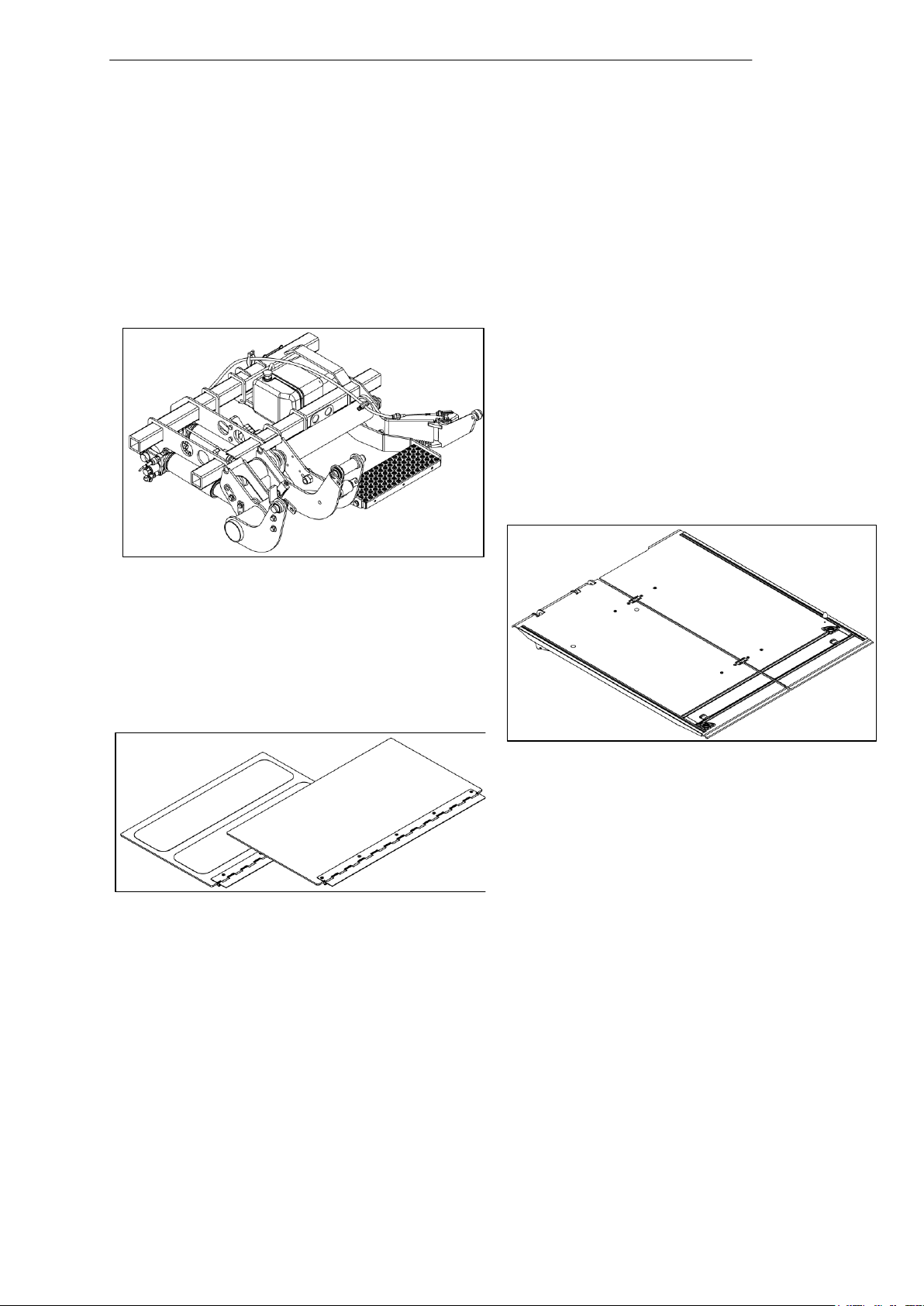
IMPORTANT: All illustrations of the lifting gear are shown without factory-installed
cables and hydraulic hoses.
2.1.1 Lifting gear
2.1.2 Platform
2.1.3 Bridge plates (20 909 431)
Page 11
Introduction
5
Fig. 4
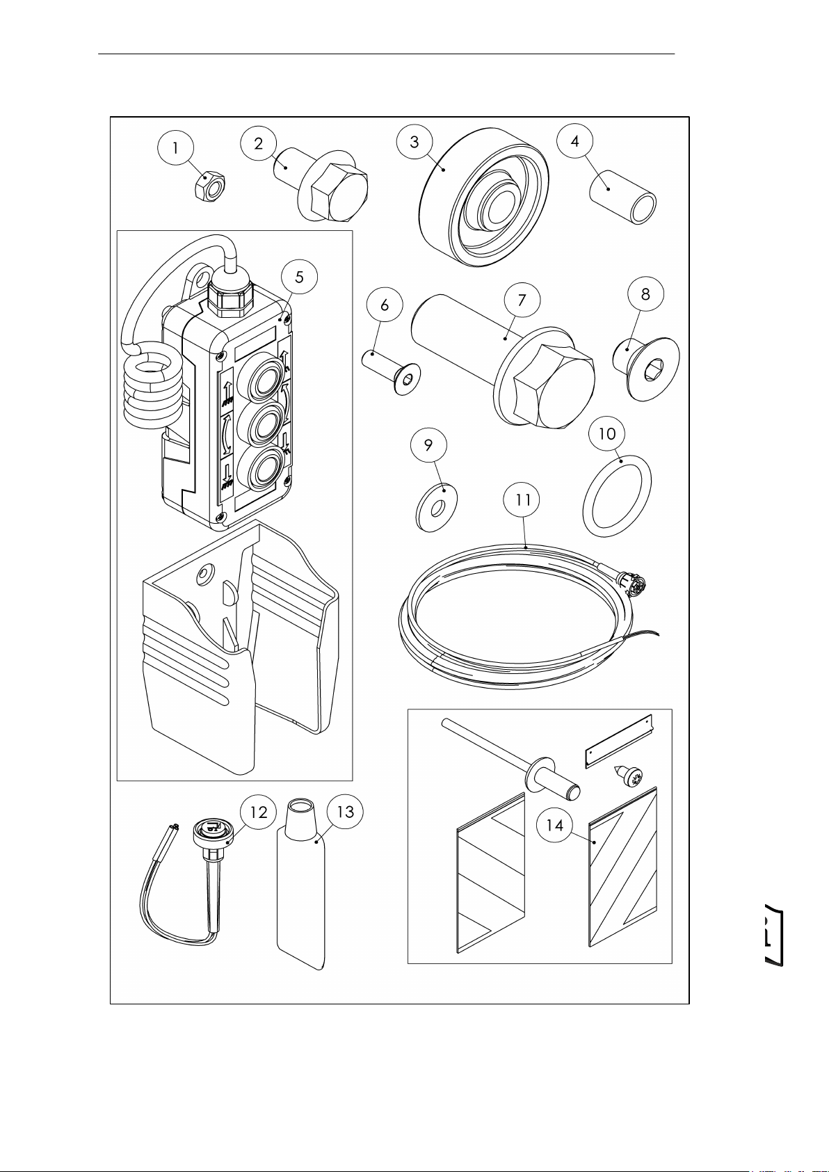
2.1.4 Accessories kit
Page 12

Introduction
6
Item
No.
Part No.
Description
Standard
Qty.
1
80 000 046
Hexagon nut
DIN 934 - M5 - A2
4
2
20 908 251
Hexagon flange bolt
DIN 6921 - M10x15 - 10.9 - ZN
2
3
20 907 616
Ground roller
2 4
20 907 615
Bushing
d20/16x32
2
5
20 907 200
Handheld control
3-button
1
6
20 904 647
Countersunk screw with
hexagon socket
ISO 10642 - M5x16 - A2
4
7
20 904 600
Flange screw
W 0263 - M16x40 - 10.9 - GEO
2
8
20 901 791
Countersunk screw with
hexagon socket
DIN 7991 - M10x12 - A2
1
9
20 850 543
Washer
DIN 9021 - D5,3 - A2
4
10
20 840 117
O-ring
40.65x5.33
6
11
20 906 975
12 m cable with VEHH
connector
1
12
20 906 974
Cabin switch
1
13
20 840 405
Lubricating grease
1 14
60 710 330
Warning flag
Kit
1
15
-------------
Accompanying
documentation
6
Parts list – accessories kit
Accompanying documents:
Inspection booklet Part No. 60 700 495
Installation manual Part No. 20 912 027
User manual Part No. 20 908 422
Oil-level sticker Part No. 20 911 907
Electrical circuit diagram Part No. 20 910 824
Hydraulic circuit diagram Part No. 20 908 421
IMPORTANT: As a general rule, only existing mounting points (holes in the vehicle
chassis) may be used for installation. Different installation adapters are available for
each vehicle type as described below.
Page 13
Introduction
7
Fig. 5
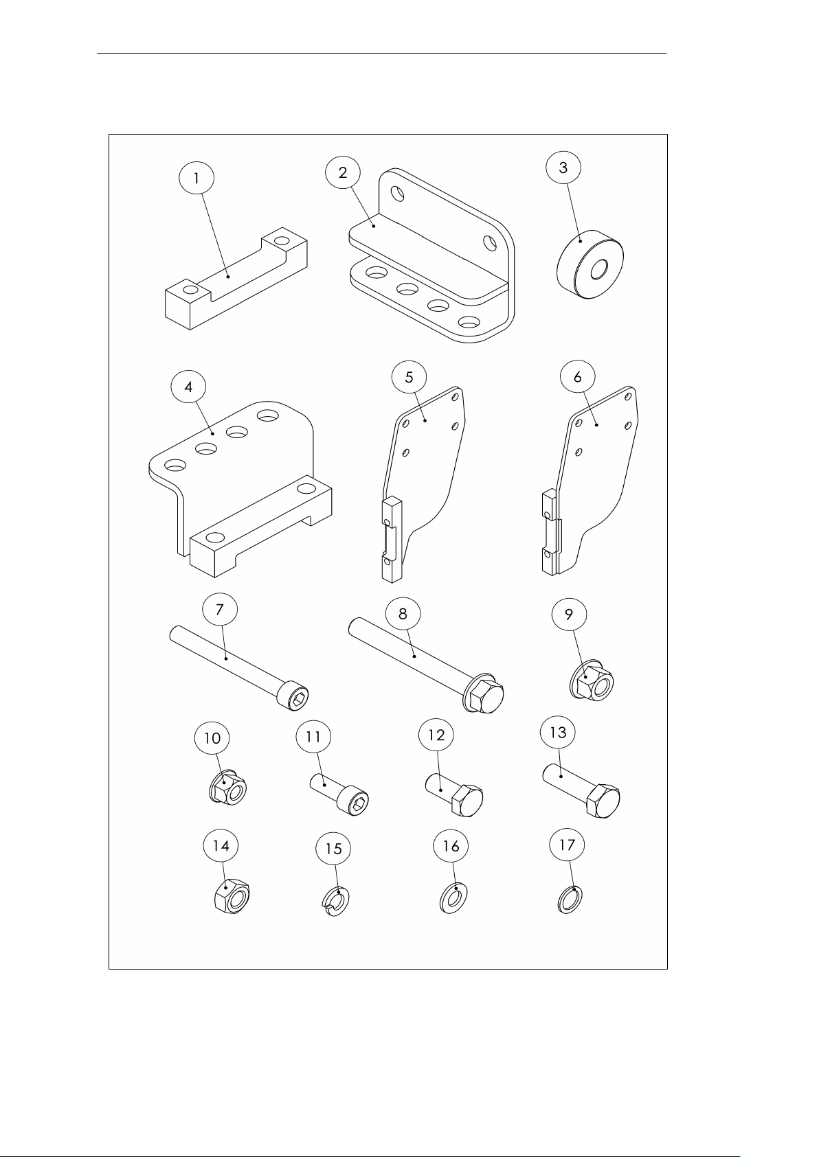
2.1.5 Installation adapter kit (22 911 216)
Page 14

Introduction
8
Item
No.
Part No.
Description
Standard
Qty.
1
20 908 103
Bracket
4
2
20 908 322
Installation adapter
2
3
20 908 395
Spacer ring
2
4
20 908 398
Installation adapter
2
5
20 908 639
Installation adapter
1
6
20 908 640
Installation adapter
1
7
20 909 327
Cheese-head screw
with hexagon socket
DIN 912 - M10x90 - 8.8 - ZN - PRE80
8
8
20 911 796
Hexagon flange bolt
MBN 10105 - M12x1.5x100 - 10.9 DBL
8
9
20 911 797
Hexagon nut with
flange and clamping
piece
MBN 13023 - M12x1.5 - 10 - DBL
8
10
20 911 864
Hexagon nut with
flange and clamping
piece
MBN 13023 - M10 - 10 - DBL
4
11
22 902 352
Cheese-head screw
with hexagon socket
ISO 4762 - M10x25 - 10.9 - ZFSHL
4
12
80 000 029
Hexagon head screw
ISO 4017 - M12x25 - 8.8 - ZFSHL
2
13
80 000 032
Hexagon head screw
DIN 933 - M12x40 - 8.8 - A2K
2
14
80 000 050
Hexagon nut
DIN 934 - M12 - 8 - A2K
2
15
80 000 061
Spring washer
DIN 127 – A – 10 - ZN
8
16
80 000 072
Washer
ISO 7089 - A - D10 - ZFSH
4
17
80 000 253
Lock washer
VS - D12 - Gal.ZN8
2
18
20 912 022
Cheese-head screw
with hexagon socket
MBN 10105 - M10x100 - 10.9 - DBL
4
Parts list – installation adapter kit (Part No. 22 911 216)
2.2 Damage during transport
After unloading, inspect the liftgate for damage. If any damage is found, record it in
writing on the shipper’s waybill so that claims can be asserted.
Page 15

Preparing for installation
9
CAUTION
Unsuitable transport equipment
When transporting and lifting heavy parts, use transport equipment (e.g. cranes,
pallet trucks, or other lifting gear) with a sufficient load carrying capacity.
Verify the correct and reliable functioning of the transport equipment.
3 Preparing for installation
3.1 Requirements for installation
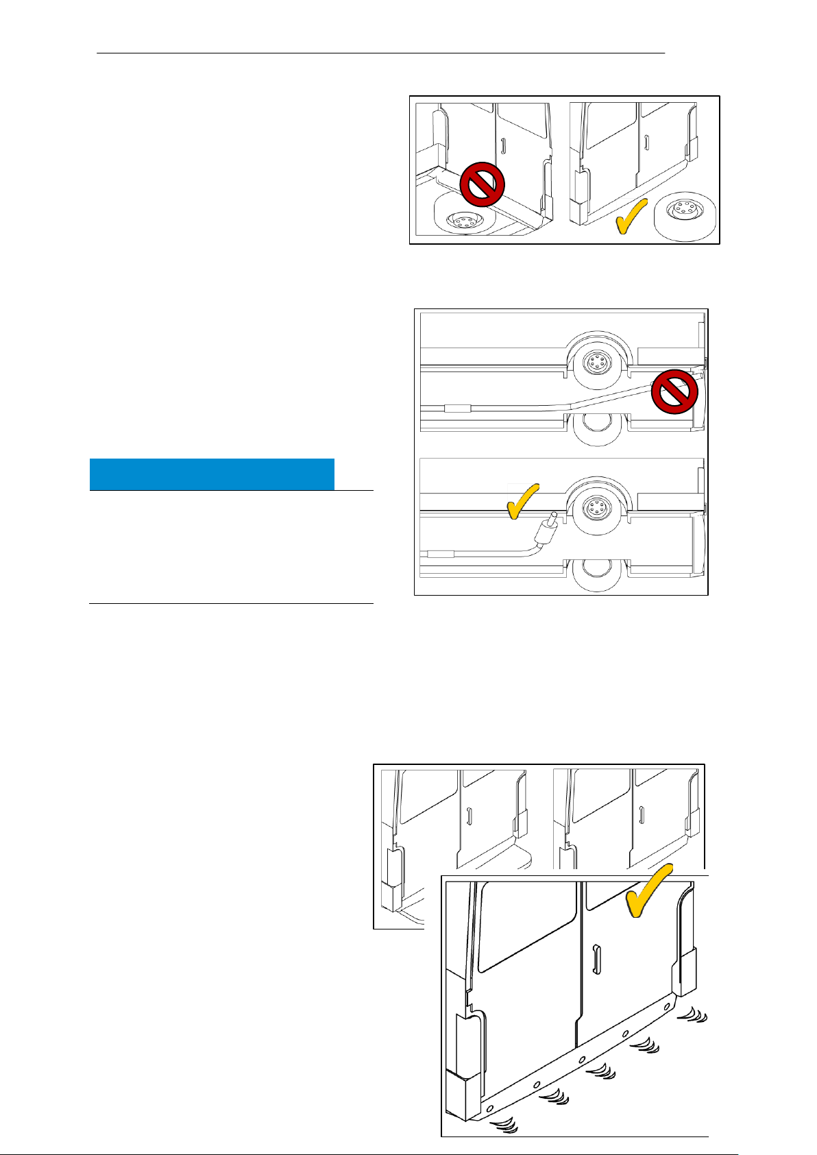
The vehicle exhaust must not be located at the rear of the vehicle.
Line the vehicle floor with wood panels. For other types of flooring, verify whether
installation is possible.
The rear doors must open to a minimum angle of 180°.
A spare tire must not be located between the rear axle and rear bumper.
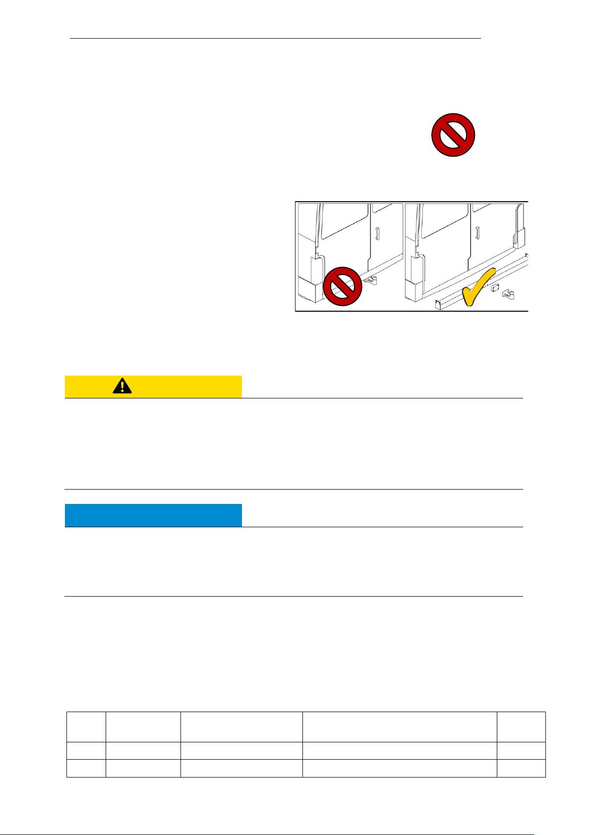
The liftgate cannot be installed if the rear bumper has an integrated step. In this
case, the vehicle must be fitted with a standard bumper.
A step must not be installed behind the bumper.
A supplementary battery and switching strip must be present.
For vehicles with rear parking sensors, the sensors will no longer function
correctly once the platform is installed, because the lifting gear interferes with the
sensors.
3.2 Lifting the vehicle
Lift the vehicle using a lifting platform.
IMPORTANT: Installation over a pit is also possible, in which case the vehicle must
also be raised (using winches or wedges) so that the liftgate and pallet can be
inserted under the vehicle.
3.3 Preparing the vehicle
Secure the vehicle in place to prevent unintentional movement.
Disconnect the vehicle battery. Follow the vehicle manufacturer’s instructions for
correctly handling the battery.
Be careful not to damage the vehicle. We recommend using appropriate
coverings.
Page 16
Preparing for installation
10
NOTICE
Be sure to maintain a sufficient
distance from heat-sensitive
parts. The minimum distance
from plastics and cables is
300 mm (see Fig. 7).
Fig. 6
Fig. 7
Fig. 8
Fig. 9
3.3.1 Remove spare tire
If the vehicle has a spare tire
between the rear axle and the rear
bumper, remove the tire
(see Fig. 6).
3.3.2 Move exhaust pipe
If the exhaust pipe is at the rear,
move it to the side.
IMPORTANT: Changes to the exhaust
system must be carried out by qualified
personnel and according to the vehicle
manufacturer’s guidelines.
3.3.3 Mount supplementary battery
If applicable, mount a supplementary battery to supply power to the liftgate.
3.3.4 Install standard bumper
on Mercedes Sprinter
If the vehicle has a bumper
with an integrated step,
replace it with a standard
bumper (see Fig. 8).
3.3.5 Deactivate parking
sensors
For vehicles with rear parking sensors,
the sensors will no longer function
correctly once the platform is installed,
Page 17
Preparing for installation
11
CAUTION
Unsecured, heavy parts
When transport locks are removed, parts may fall or tip over and the platform may tip
over. Risk of injury.
Secure loose parts. Remove transport locks carefully.
After disposing of packing materials, store all parts in a secured manner.
NOTICE
Oil leakage
Incorrect positioning of the lifting gear can result in oil leakage. Risk of environmental
damage.
Always transport the lifting gear in an upright position using suitable lifting points.
Item
No.
Part No.
Description
Standard
Qty.
1
20 908 103
Bracket
4
2
20 908 322
Installation adapter
2
Fig. 10
because the lifting gear interferes with the sensors (see Fig. 9).
3.3.6 Remove trailer hitch or step
If a trailer hitch or step is mounted
on the vehicle, remove it
(see Fig. 10).
3.4 Unpacking the lifting
gear, installation adapters, and accessories kit
Check the scope of delivery for completeness (see pages 4 – 8).
IMPORTANT: Dispose of all packing materials in accordance with environmental
regulations.
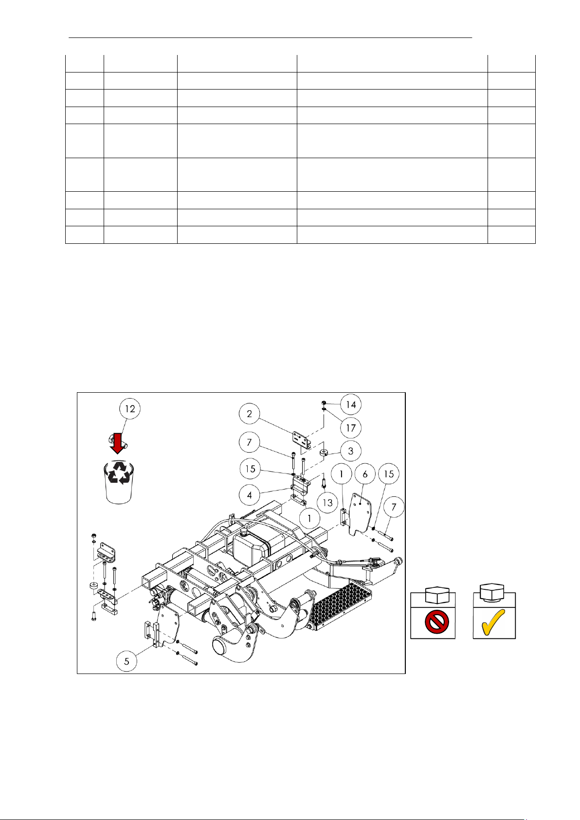
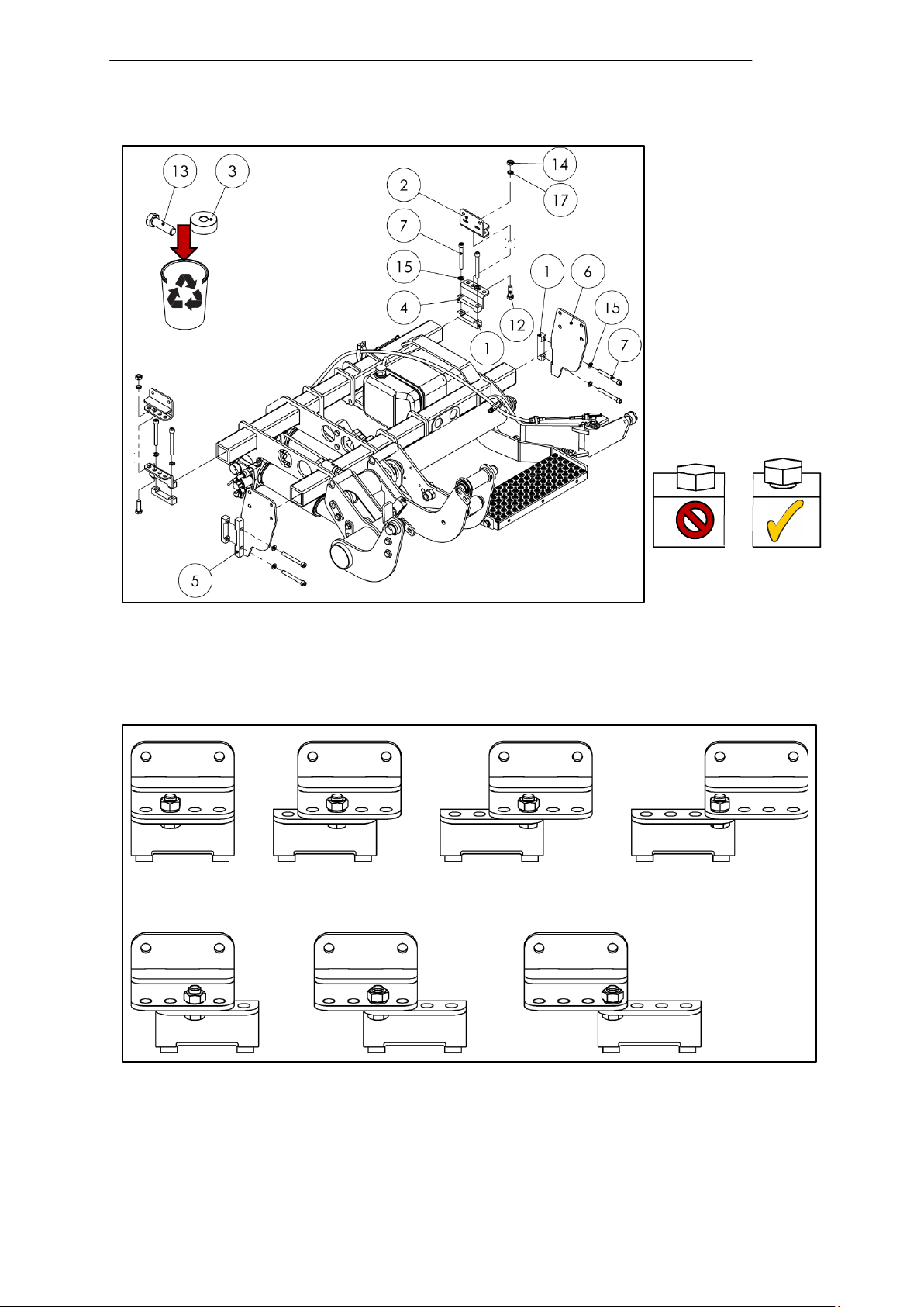
3.5 Pre-installing the installation adapters
Required material from installation adapter kit (Part No. 22 911 216)
Page 18
Preparing for installation
12
3
20 908 395
Spacer ring
2
4
20 908 398
Installation adapter
2
5
20 908 639
Installation adapter
1
6
20 908 640
Installation adapter
1
7
20 909 327
Cheese-head screw
with hexagon socket
DIN 912 - M10x90 - 8.8 - ZN PRE80
8
12
80 000 029
Hexagon head screw
ISO 4017 - M12x25 - 8.8 ZFSHL
2
13
80 000 032
Hexagon head screw
DIN 933 - M12x40 - 8.8 - A2K
2
14
80 000 050
Hexagon nut
DIN 934 - M12 - 8 - A2K
2
15
80 000 061
Spring washer
DIN 127 - A - 10 - ZN
8
Fig. 11
Pre-install the installation adapters on the liftgate’s lifting gear as shown in Fig. 11
or Fig. 13, tightening the fittings until hand-tight.
IMPORTANT: Depending on the vehicle, choose either the 3.5 ton (see Fig. 11) or 5
ton (see Fig. 13) installation version.
Vehicle with maximum authorized mass of 3.5 tons
(for 5 ton vehicles, see next page)
Page 19
Preparing for installation
13
Fig. 12
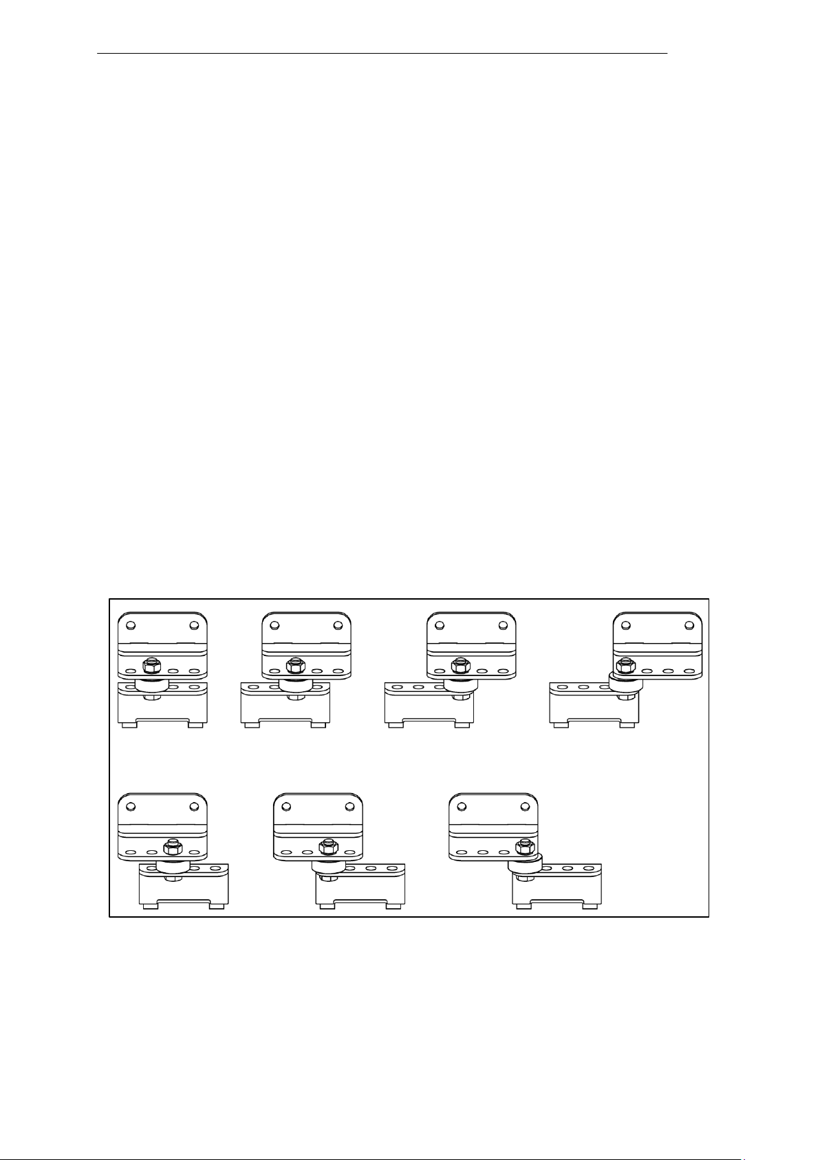
Depending on requirements, different installation options are available for the front
installation adapters (2 and 4) in the installation adapter kit (Part No. 22 911 216)
(see Fig. 12).
Page 20
Preparing for installation
14
Fig. 13
Fig. 14
Vehicle with maximum authorized mass of 5 tons
(for 3.5 ton vehicles, see previous page)
Depending on requirements, different installation options are available for the front
installation adapters (2 and 4) in the installation adapter kit (Part No. 22 911 216)
(see Fig. 14).
Page 21
Preparing for installation
15
Fig. 16
Fig. 17
Fig. 15
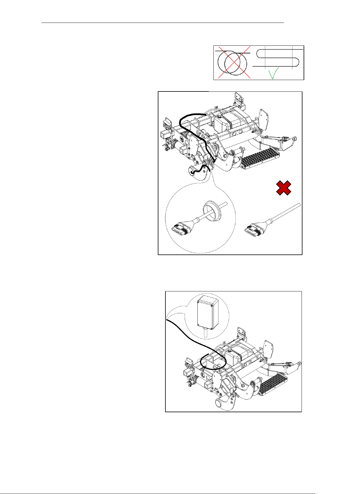
3.6 Installing the cables/preparation
IMPORTANT: Excess cable must not be wound up
in a coil but must be placed in slings.
(Fig. 15).
3.6.1 Cable to the platform
Route the control unit cable for
platform connection (white
plastic cover) to the swing-arm
assembly in the center of the
vehicle (Fig. 16).
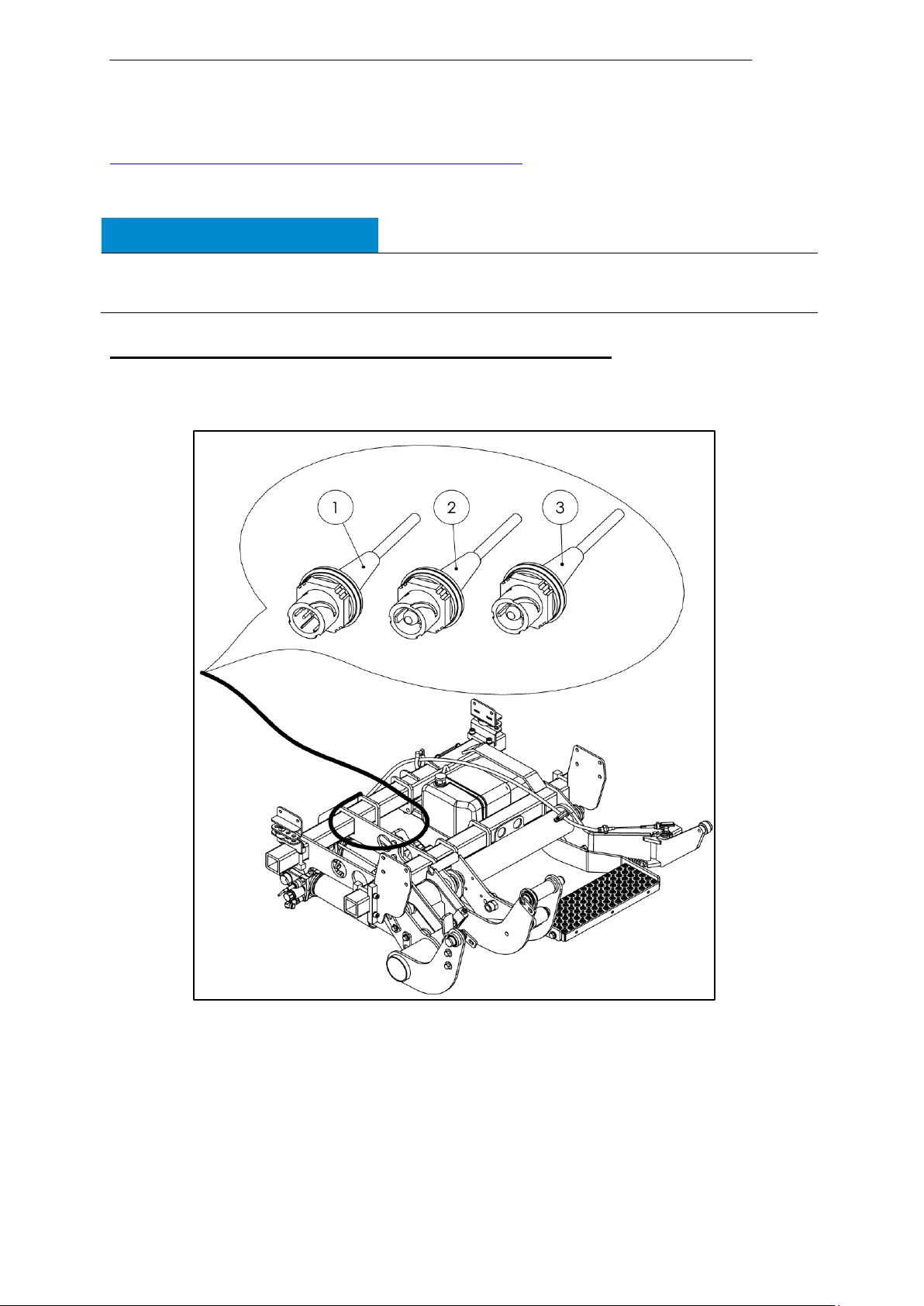
3.6.2 Cable for the service
switch
Route the control unit cable for
service switch connection to the
vehicle cargo area (Fig. 17).
Page 22
Preparing for installation
16
NOTICE
When installing cables, make sure they are safe from chafing.
Do not install cables near heat-dissipating components.
Fig. 18
3.6.3 Routing the cables to the front of the vehicle
For more information, look online under
http://www.taillift.org/en/electrical-vehicle-interface
IMPORTANT: Follow the vehicle manufacturer’s installation guidelines.
With preparation according to ETMA Code A and Code B
Route the power cable and the cable for the cabin switch unit to the junction box
provided (Fig. 18).
Legen
d:
Item 1 Connector for cabin switch unit Part No. 20 910 754
Item 2 Connector for positive cable (red) Part No. 20 907 673
Item 3 Connector for negative cable (blue) Part No. 20 907 673
Page 23
Preparing for installation
17
NOTICE
Do not yet connect the cables.
Fig. 19
Fig. 20
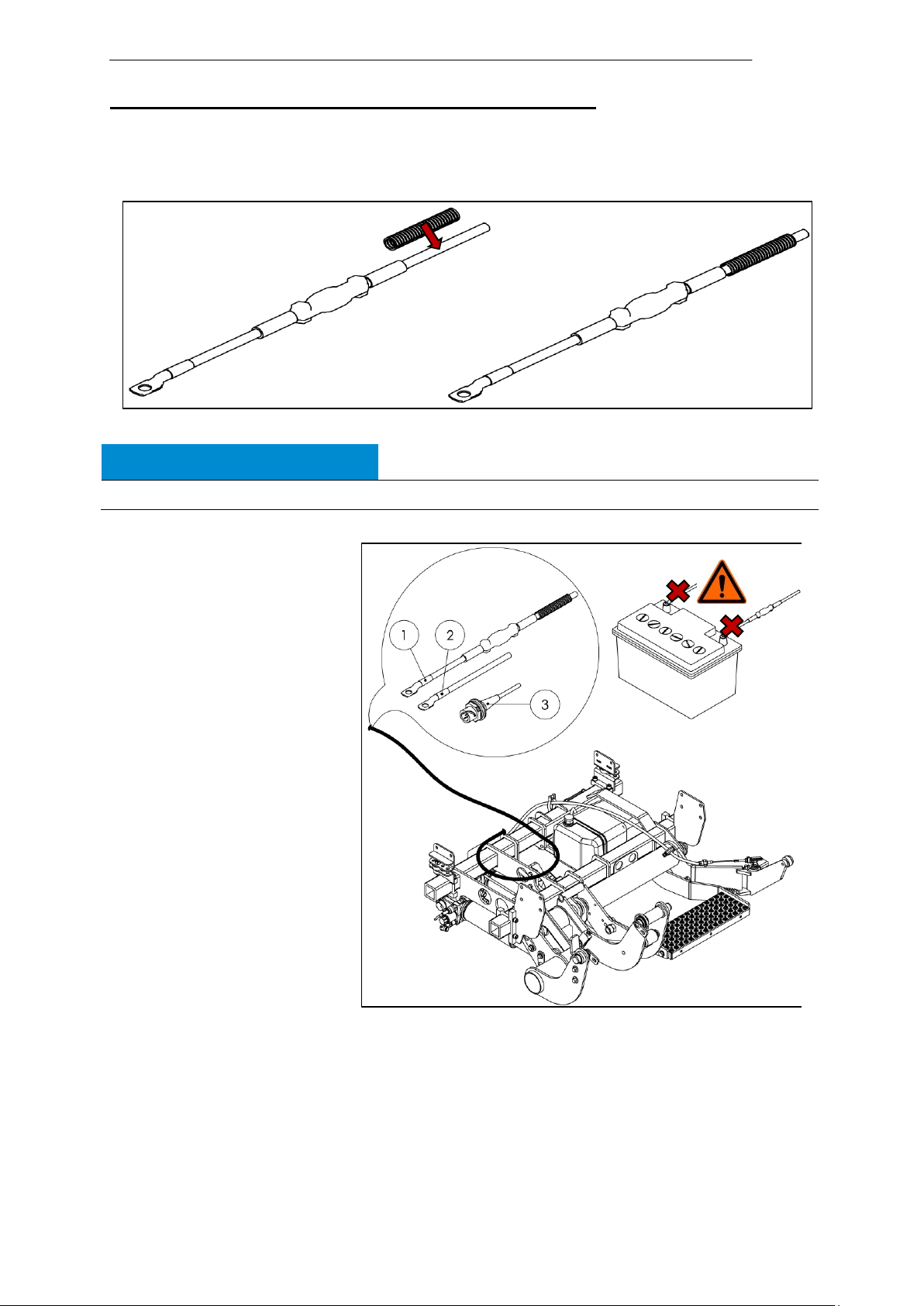
No preparation according to ETMA Code A and Code B
Power cable
Insert the positive cable (25 mm² red) (“power unit cable”) for the power supply
into a length of slit corrugated tubing (see Fig. 19).
Route the positive cable
(red) and negative cable
(blue) to the terminals but
do not yet connect them
(see Fig. 20).
Legend:
Item 1 Positive cable (red) Part No. 20 907 673
Item 2 Negative cable (blue) Part No. 20 907 673
Item 3 Connector for cabin switch unit Part No. 20 910 754
Page 24

Preparing for installation
18
Fig. 22
click!
Cable for cabin switch unit
Route the cabin switch cable from the accessories kit (Item No. 11) to the
driver’s cabin (see Fig. 21).
Connect the cabin switch cable to the 7-pin connector (DIN 72585) from the
control unit.
Fig. 21
Legend:
Item 1 7-pin connector (DIN 72585) from control unit
Item 2 Connector for cabin switch unit Part No. 20 910 754
3.6.4 Control panel cable on the
control unit
Route the control unit cable for
control panel connection to the
right as viewed in the forward
direction of travel (see Fig. 22).
3.6.5 Handheld control
Page 25

Preparing for installation
19
Fig. 23
Fig. 24
1
(optional)
Prepare the cable on the control unit
Sever the control unit cable (1, red
marking with cable tie) for connecting
the handheld control (see Fig. 23)
Leave the end without a cable tie
blank.
Strip the end of the control unit cable section with a red marking for connecting the
handheld control (see Fig. 24).
Page 26

Preparing for installation
20
Fig. 25
Fig. 26
Handheld control
Determine the installation
location for the handheld
control and route the cable to
the installation location
(see Fig. 25).
Find the bushing into the cargo
area.
3.7 Aligning the lifting
gear
Align the lifting gear under
the vehicle on a mounting
tool or pallet (see Fig. 26).
Page 27

Preparing for installation
21
Fig. 27
Line up the installation adapters on the lifting gear with the manufacturer’s holes
in the vehicle chassis (see Fig. 27).
3.8 Mounting holes on the vehicle
IMPORTANT: Follow the vehicle manufacturer’s installation guidelines.
Find the mounting holes on the vehicle.
Make any new mounting holes that are necessary.
If necessary, weld spacer sleeves onto the vehicle chassis.
Remove underbody coating in the area of the mounting points (contact surfaces
between vehicle and installation adapters).
Seal any areas of the vehicle body that are thus exposed (with corrosion
protection).
Page 28

Installation
22
Fig. 28
4 Installation
4.1 Positioning the lifting gear
Place the prepared lifting gear (on a pallet) under the vehicle using a suitable
means of transport, e.g. pallet truck, forklift, etc. (see Fig. 28).
Page 29

Installation
23
WARNING
Installation at crushing and shearing points
Fingers are at risk of being crushed or sheared when the lifting gear is installed on
the vehicle.
Be careful at the connecting points between the lifting gear and vehicle.
NOTICE
Do not damage cables.
Item
No.
Part No.
Description
Standard
Qty.
8
20 911 796
Hexagon flange bolt
MBN 10105 - M12x1.5x100 - 10.9 DBL
8
9
20 911 797
Hexagon nut with
flange and clamping
piece
MBN 13023 - M12x1.5 - 10 - DBL
8
Fig. 29
4.2 Tightening the lifting gear fittings until hand-tight
Raise the lifting gear. Insert the rear bolts (installation adapter kit – Part No. 22
911 216) as viewed in the forward direction of travel and tighten until hand-tight
as shown in Fig. 29.
Excerpt from parts list: Installation adapter kit (Part No. 22 911 216)
Page 30

Installation
24
NOTICE
Do not damage cables.
Item
No.
Part No.
Description
Standard
Qty.
10
20 911 864
Hexagon nut with flange
and clamping piece
MBN 13023 - M10 - 10 - DBL
4
11
22 902 352
Cheese-head screw with
hexagon socket
ISO 4762 - M10x25 - 10.9 ZFSHL
4
16
80 000 072
Washer
ISO 7089 - A - D10 - ZFSH
4
Fig. 30
Insert the front bolts (installation adapter kit – Part No. 22 911 216) as viewed
in the forward direction of travel and tighten until hand-tight as shown in Fig. 30.
Excerpt from parts list: Installation adapter kit (Part No. 22 911 216)
Page 31

Installation
25
NOTICE
Do not damage cables
Item
No.
Part No.
Description
Standard
Qty.
10
20 911 864
Hexagon nut with flange
and clamping piece
MBN 13023 - M10 - 10 - DBL
4
18
20 912 022
Cheese-head screw with
hexagon socket
ISO 4762 - M10x - 10.9 ZFSHL
4
Fig. 31
Optional: Insert the front bolts (installation adapter kit – Part No. 22 911 216) as
viewed in the forward direction of travel and tighten until hand-tight as shown in Fig. 31.
Legend:
a Welded-on bushing as per manufacturer’s installation guidelines
Excerpt from parts list: Installation adapter kit (Part No. 22 911 216)
Page 32

Installation
26
Fig. 32
4.3 Securing the lifting gear to the vehicle
Secure the lifting gear (with adapters) to the vehicle and tighten to a torque of
115 Nm in the rear and 70 Nm in front (see Fig. 32).
Page 33

Installation
27
Fig. 34
Fig. 33
Fig. 35
4.4 Laterally
aligning the
lifting gear
Shift the lifting gear to
the left so that the
brand emblem on the
rear door does not
collide with the platform
(see Fig. 33).
4.5 Securing the axle
assemblies
Secure the installation adapters to the
lifting gear and tighten to the specified
torque of 53 Nm (see Fig. 34).
4.6 Securing the installation
adapters
Secure the front installation adapters
to the lifting gear and tighten to a
torque of 70 Nm (see Fig. 35).
Page 34

Installation
28
Fig. 36
4.7 Connecting the cables to the lifting gear
4.7.1 Installing and connecting the service switch
Disconnect the service switch box from the cable by loosening the screw
terminals in the housing (see Fig. 36).
Legend:
Terminal 30 Black cable
Terminal Y1 Blue cable
Terminal KM Gray cable
Terminal YA Brown cable
Terminal Y3 Green/yellow cable
Route the cable to the cargo area via a bushing opening.
Reconnect the service switch to the routed cable as shown in Fig. 36.
Secure the service switch box.
Page 35

Installation
29
WARNING
Penetration of water
Over the long term, the improper installation of cables can result in water penetrating
the control panel and causing it to malfunction.
Risk of serious injury in subsequent operation.
Route the cable to the control panel only from below.
Fig. 37
4.7.3 Installing and connecting the control panel
Mount the control panel on door
Route the control panel cable to the cargo area so that it can be secured to the
right-hand door (a) (protect against kinks and ensure correct cable length for fully
opened door, using corrugated tubing if necessary) (see Fig. 37).
Disassemble the control panel SUPERSEAL connector and, if appropriate, the
control unit SUPERSEAL connector so that the control panel cable can be
routed to the control unit cable via openings.
Page 36

Installation
30
Control unit wires (1)
Pin No. and Wire No.
Control panel wires (2)
Black
1
Black
Brown
2
Black
Gray
3
Black
Blue
4
Black
White
5
Green/yellow
Green/yellow
6
Fig. 40
Fig. 39
Fig. 42
Fig. 44
Fig. 38
Fig. 41
Fig. 43
IMPORTANT: A release tool is required for disassembling the SUPERSEAL
connector.
IMPORTANT: When
reassembling, pay
attention to the position of
the individual wires! Return
the wires to their original
positions (see Fig. 39 for 1
and Fig. 38 for 2).
Legend:
Item 1 Socket housing
(Fig. 39) of the control unit
Item 2 Pin housing (Fig. 38) of the control panel
Using the release tool,
release the safety guard
from the socket housing
and pin housing (see
Fig. 40 and Fig. 41).
For the socket
housing, release
the latches on the
contact pins and
pull the wires out of
the back of the
housing (see
Fig. 42 and Fig. 43).
For the pin housing, first use the
release tool to pry out the safety
guard (see Fig. 44).
Page 37

Installation
31
Fig. 46
Fig. 45
For the pin housing, release the latches on the contact pins and pull the wires out
of the back of the housing (Fig. 45 and Fig. 46).
Reassemble the control panel SUPERSEAL connector and the control unit
SUPERSEAL connector.
Page 38

Installation
32
Item No.
Part No.
Description
Standard
Qty.
1
80 000 046
Hexagon nut
DIN 934 - M5 - A2
4
6
20 904 647
Countersunk screw
with hexagon socket
ISO 10642 - M5x16 - A2
4
9
20 850 543
Washer
DIN 9021 - D5,3 - A2
4
Fig. 47
click!
Fig. 48
X
Connect the control panel connector (1) to the control unit connector (2) (see
Fig. 47).
Legend:
Item 1 Connector from control
panel for connection to
control unit
Item 2 Connector from control
unit for connection to
control panel
Secure the control panel (b) to the right-hand vehicle door (a) using the fasteners
(1, 6, 9) from the accessories kit, maintaining a distance of 400 mm +/-100 mm
(15 ¾” +/- 1 15/16”) as per specifications
(see Fig. 37 und Fig. 48).
Required material from accessories kit
Legend:
Item a Right-hand vehicle door
Item b Control panel
X = distance
400 mm +/-100 mm
(15 3/4“ +/- 1 15/16“)
Page 39

Installation
33
Connection
Function
Control unit cable
Handheld control cable
+
+
Black wire
Red wire
1
Lift
Blue wire
Blue wire
2
Lower
Gray wire
Gray wire
3
Tilt up/down
Brown wire
Brown wire
4
31 (ground)
Green/yellow wire
Fig. 50
Fig. 49
4.7.4 Connecting the handheld control (optional)
Connect the cable from the handheld control (2) to the stripped control unit cable
section (1) with the red marking at the installation location (see Fig. 49).
Legend:
Item 1 Control unit
Item 2 Handheld control
4.7.5 Mounting the bracket for the handheld control (optional)
Mount the bracket (1) for the handheld control (2) on the vehicle wall (3) using, for
example, 2 screws or adhesive (see Fig. 50).
Legend:
Item 1 Bracket for handheld control
Item 2 Handheld control
Item 3 Vehicle wall
4.7.6 Connecting the cables (front of
Page 40

Installation
34
WARNING
Vehicle battery short-circuit
Improper connection of the device to the vehicle battery can cause a short-circuit
and explosion of the battery.
Risk of damage to property, fire, and injury.
Follow the vehicle manufacturer’s instructions for correctly handling the battery.
NOTICE
Connect cables only to cables of the same color.
Fig. 51
click!
click!
click!
vehicle)
With preparation according to ETMA Code A and Code B
Connect the power cable and the cable for the cabin switch unit to the sockets
provided (see Fig. 51).
Legend:
Item 1 Connector for cabin switch unit Part No. 20 910 754
Item 2 Positive cable (red) Part No. 20 907 673
Item 3 Negative cable (blue) Part No. 20 907 673
Item 4 7-pin connector (DIN 72585) from control unit
Item 5 Connector for positive cable
Item 6 Connector for negative cable
Page 41

Installation
35
Item No.
Part No.
Description
Qty.
11
20 906 975
Cabin switch unit cable 12 m with VEHH
connector
1
12
20 906 974
Cabin switch
1
Fig. 52
Fig. 53
No preparation according to ETMA Code A and Code B
Power cable
Route the “power unit cable,” positive cable, and negative cable (25 mm²) for the
power supply to the terminals provided for the battery and connect (see example
in Fig. 52).
Cabin switch unit
Drill a 16 mm dia. hole for the cabin switch (12) in a suitable location on the
dashboard.
Snap the cabin switch (12) into the hole.
Route the cabin switch unit cable (11) from the lifting gear to the front.
Connect the cabin switch unit as shown in Fig. 53.
Excerpt from parts list: accessories kit
Page 42

Installation
36
Fig. 54
4.8 Unpacking the platform
Check the scope of delivery for completeness (see pages 4f.)
IMPORTANT: Dispose of all packing materials in accordance with environmental
regulations.
4.9 Raising the platform
Lift the platform using suitable means, e.g. crane, assembly table, or pallet truck
and pallet (see Fig. 54).
Page 43

Installation
37
WARNING
Installation at crushing and shearing points
Fingers are at risk of being crushed or sheared when the platform is installed on the
lifting gear.
Be careful at the connecting points between the platform and lifting gear.
Item No.
Part No.
Description
Standard
Qty.
10
20 840 117
O-ring
40.65 x 5.33
6
Fig. 55
Fig. 56
4.10 Installing the platform
Remove the transport lock (cable tie).
R
e
m
ov
e
th
e
pi
ns
(a,
b,
c)
(s
ee
Fig. 55).
Legend:
Item a Pin Part No. 20 905 057
Item b Pin Part No. 20 840 722
Item c Pin Part No. 20 907 775
Thread 6 O-rings (accessories kit parts list – Item No. 10) onto the steel bushings
(see Fig. 56).
Exc
erp
t
fro
m
par
ts
list:
acc
ess
ori
es
kit
Page 44

Installation
38
Item No.
Part No.
Description
Standard
Qty.
13
20 840 405
Lubricating grease
1
Fig. 57
Fig. 58
Loosen the platform stop (1) and push it toward the vehicle
(see Fig. 57).
Legend:
Item 1 Platform stop
Thoroughly grease the bearing bushes with the special assembly grease
(accessories kit parts list – Item No. 13) (see Fig. 58).
Excerpt from parts list: accessories kit
Page 45

Installation
39
Item No.
Part No.
Description
Standard
Qty.
2
20 908 251
Hexagon flange
bolt
DIN 6921 - M10x15 - 10.9 - ZN
2
Fig. 59
Fig. 60
Align the top bearing points of the platform (platform attachment points) with the
swing-arm bearing points (top attachment points of the lifting gear)
(see Fig. 59).
Insert the two pins (a, b) through the top attachment points of the platform and
the attachment points of the swing-arm assembly.
IMPORTANT: Note the direction of insertion (see Fig. 60).
Mount the bolts from the accessories kit (2) to secure the pins and tighten them
to 70 Nm.
Excerpt from parts list: accessories kit
Legend:
Item a Pin Part No. 20 905 057
Item b Pin Part No. 20 840 722
Page 46

Installation
40
Item No.
Part No.
Description
Standard
Qty.
8
20 901 791
Countersunk screw with
hexagon socket
DIN 7991 - M10x12 - A2
1
Fig. 61
Fig. 62
Lift the tip of the platform until the closing-rod bearing point (attachment point for
the closing rod) is aligned with the swing-arm bearing point (bottom attachment
point on the platform) (see Fig. 61).
IMPORTANT: If necessary, slightly retract or extend the closing rod.
Insert the pin (c).
Mount the screw (8) from the accessories kit to secure the pin (Fig. 62).
Excerpt from parts list: accessories kit
Legend:
Item c Pin Part No. 20 907 775
Page 47

Installation
41
Item No.
Part No.
Description
Standard
Qty.
10
20 840 117
O-ring
40.65 x 5.33
6
Fig. 63
Fig. 64
Move the 6 pre-fitted O-rings (accessories kit parts list – Item No. 10) into their
correct positions (see Fig. 63).
IMPORTANT: All bearing points are sealed with O-rings.
Excerpt from parts list: accessories kit
4.11 Mounting the platform
lock on the closing arm
Remove and properly dispose of
the nut on the transport lock (1)
(see Fig. 64).
Legend:
Item 1 Nut Part No. 80 000 052
Page 48

Installation
42
Item No.
Part No.
Description
Standard
Qty.
3
20 907 616
Ground roller
2 4
20 907 615
Bushing
d20/16x32
2
7
20 904 600
Flange screw
W 0263 - M16x40 - 10.9 - GEO
2
Fig. 65
Fig. 66
Mount the screw (1) for the
platform lock, including the spring
washer (2), washers (3), and
sleeve (4), on the platform
bearing (see Fig. 65).
Legend:
Item 1 Hexagon head screw
Item 2 Spring washer
Item 3 Washer
Item 4 Sleeve
4.12 Mounting the ground rollers
Required material from accessories kit
Remove the flange
screws (7), bushings (4),
and ground rollers (3)
from the accessories kit
(see Fig. 66).
Page 49

Installation
43
WARNING
Shift in center of gravity and lifting up of front end of the vehicle
Unexpected movements of the vehicle can result in the severe injury or death of
bystanders.
Follow the vehicle manufacturer’s installation guidelines. If necessary, install
supports.
Fig. 67
click!
4.13 Installing supports (vehicle-dependent)
With some vehicle types and installation versions, maximum loading of the platform
can cause the front of the vehicle to lift up.
4.14 Connecting the platform to the electrical system
4.14.1 Connecting the platform cable to the electrical system
Connect the platform cable connector (1) to the control unit connector (2) (see
Fig. 67)
IMPORTANT: The control unit connector is identified by the white plastic cover on
the cable.
Legend:
Item 1 Platform connector for connection to control unit
Item 2 Control unit connector for connection to platform
Page 50

Installation
44
Fig. 69
Fig. 68
4.14.2 Connecting the
license plate light
Find the cable connection
point for the license plate
light in the C column (a)
on the Mercedes Benz
Sprinter (see Fig. 68).
Route the license plate
light cable (2) (cable
outlet from platform’s
aluminum torsion box)
along the closing arm
(see Fig. 69).
Legend:
Item b License plate light
Join the two cables (1) and (2) and connect.
IMPORTANT: Follow the vehicle manufacturer’s installation guidelines.
Page 51

Installation
45
Item
No.
Part No.
Description
Standard
Qty.
14
60 710 330
Warning flag
Kit
1
Fig. 70
Fig. 71
4.15 Mounting the license plate holder
Mount the license plate holder below the license plate light.
IMPORTANT: When positioning the holder, make sure the license plate is sufficiently
illuminated.
4.16 Mounting the bridge plates (20 909 431)
Fasten the bridge plate with the non-skid coating (2) on the right side. The non-
skid coating must face upward when the bridge plate is folded shut (see Fig. 70).
Fasten the non-coated bridge plate (1) on the left side (see Fig. 70).
Legend:
Item 1 Bridge plate
Part No. 20 911 718
Item 2 Bridge plate
Part No. 20 911 699
4.17 Mounting the warning flags
Remove the warning flag kit (14, Part No. 60 710 330) from the accessories kit
and mount it in accordance with the installation instructions below (Fig. 71,
Fig. 72, and Fig. 73).
Required material from accessories kit
IMPORTANT: Mounting specifications: Comply with
these mounting specifications (see Fig. 71):
Dimension A – Move the holder far enough away from
the tip of the platform to leave 20 mm clearance
between the holder and the ground when the platform is
lowered. The holder must not touch the ground when the
platform is lowered.
Dimension B – Position the warning flag as close as
possible to the outside platform edge.
Page 52

Installation
46
Fig. 72
Close the liftgate (place in driving position).
Align the warning flag holder (14c).
IMPORTANT: Comply with the mounting specifications.
Transfer the existing holes in the warning flag holder to the platform and pre-drill
holes for the 2 blind rivets.
Rivet the warning flag holder (14c) using 2 blind rivets (14d).
Slide the left warning flag (14a) into the slot in the warning flag holder (14c).
IMPORTANT: Identify the left warning flag (14a) by the angle of the pattern
(see Fig. 72).
Secure the warning flag using the Phillips-head screw (14e).
Legend:
Item 14a Left warning flag
Item 14b Right warning flag
Item 14c Warning flag holder
Item 14d Blind rivet
Item 14e Phillips-head screw
Page 53

Installation
47
CAUTION
Not a normal operating position
Risk of injuring yourself or damaging the vehicle or liftgate.
Fig. 73
Move the liftgate to the horizontal position.
Fold out (open) the liftgate.
Bring the open liftgate as far as necessary into the vertical position to comfortably
mount the right warning flag.
Align the warning flag holder (14c).
IMPORTANT: Comply with the mounting specifications.
Transfer the existing holes in the warning flag holder to the platform and pre-drill
holes for the 2 blind rivets.
Rivet the warning flag holder (14c) using 2 blind rivet (14d).
Slide the right warning flag (14a) into the slot in the warning flag holder (14c).
IMPORTANT: Identify right warning flag (14a) by the angle of the pattern (see
Fig. 73).
Secure the warning flag using the Phillips-head screw (14e).
Legend:
Item 14a Left warning flag
Item 14b Right warning flag
Item 14c Warning flag holder
Item 14d Blind rivet
Item 14e Phillips-head screw
Page 54

Installation
48
4.18 Affixing the danger notice sticker
Affix the danger notice sticker “Safe handling of the liftgate.”
IMPORTANT: This sticker is supplied with all new liftgates. The installing company
must place it in an easily visible location on the inside of the vehicle cargo area.
The danger notice sticker uses pictograms to indicate potential incorrect and correct
use of the liftgate.
Page 55

Adjusting the liftgate
49
NOTICE
If no readjustment is necessary, make sure that the screws (1 and 3) are securely
tightened.
Fig. 74
Fig. 75
3
5 Adjusting the liftgate
5.1 Setting the lift height to the vehicle floor level using the
adjustable stop on the axle assembly
Use the adjustment screw (1) pre-mounted on the axle assembly of the X1A
600F/GPC X1 and an appropriate tool (e.g. a ring wrench) to set the lifting gear to the
desired height with relation to the vehicle floor.
Use the adjustment screw (1)
to set the lift height
(see Fig. 74).
Rotate to left:
lower lift height
Rotate to right:
higher lift height
Legend:
Item 1 Adjustment screw
5.2 Aligning the platform parallel to the vehicle floor
To align the platform parallel to the vehicle floor, adjust the lifting gear using the
left-hand adjustment fork (adjustment screw accessible from above) (see
Fig. 75).
With the platform open,
operate the lifting gear
to the height of the
vehicle floor (not
against the stop).
Legend:
Item 1 Adjustment screw
Item 2 Adjustment fork
Item 3 Hex bolt
Page 56

Adjusting the liftgate
50
Fig. 76
Fig. 77
Loosen the hex bolt (3).
Rotate the adjustment screw (1) to the left or right.
Rotating the adjustment screw (1) to the right moves the right side of the platform
closer to the vehicle chassis. This slightly lifts the platform on the right side of the
vehicle (see Fig. 76).
Rotating the adjustment screw (1) to the left moves the right side of the platform
away from the vehicle chassis. This slightly lowers the platform on the right side
of the vehicle (see Fig. 76).
W
h
e
n
f
i
n
i
s
h
e
d
a
d
justing, tighten the bolt (3) for securing the torsion bar to 115 Nm (see torque
table on page on page 68 and see Fig. 77).
5.3 Alignin
g the
platfor
m
(foldov
er
section)
parallel
to the
vehicle
floor
Page 57

Adjusting the liftgate
51
Fig. 78
Fig. 79
If necessary, adjust the height of the foldover section on the right side of the platform
using the right-hand adjustment fork (2) (adjustment screw accessible from below)
(see Fig. 78).
Legend:
Item 1 Adjustment screw
Item 2 Adjustment fork
Item 3 Hex bolt
Item 4 Support arm
Use the adjustment screw (1) to set the support arm (4) so that the platform stop
rests on and is supported by the support arm (4).
IMPORTANT: At the same time, check the stop (Section 5.4) on the foldover
section.
Rotating the adjustment screw (1) to the right lifts the support arm (4).
Rotating the adjustment screw (1) to the left lowers the support arm (4)
(see Fig. 79).
When finished adjusting, tighten the bolt (3) for securing the torsion bar to
11
5
N
m
(se
e
tor
qu
e
tab
le
on
pa
ge
68).
Page 58

Adjusting the liftgate
52
Fig. 80
5.4 Checking the stop on the foldover section of the platform
Check the stop on the foldover section of the platform.
IMPORTANT: The roller (1) on the support arm (2) must remain against the stop (3)
throughout the entire lifting process. If necessary, loosen the stop (3) and shift it
slightly by loosening 2 cheese-head screws (4). At the same time, the stop (3) must
not be shifted too far. When the platform is folded over, the plastic spacer (5) must
hold the platform in place (see Fig. 80).
Legend:
Item 1 Roller on support arm
Item 2 Support arm (supports foldover section of platform when platform is open)
Item 3 Stop (on foldover section of platform)
Item 4 Cheese-head screw (2 pieces)
Item 5 Plastic spacer (holds platform in driving position)
Page 59

Adjusting the liftgate
53
Fig. 81
Fig. 82
3°- 4°
5.5 Setting the end stop for the closed platform
The end stop for the platform in the closed position is mounted on the closing arm.
The platform requires no additional stops on the vehicle.
IMPORTANT: Adjust the platform so that it stands vertically behind the vehicle when
closed and in the driving position.
L
o
o
s
e
n
t
h
e
2
s
c
r
e
ws (1) on the clamping plate (2) (see Fig. 81).
Hydraulically close the platform
until not quite vertical, leaving it
open 3° to 4° (see Fig. 82).
Page 60

Adjusting the liftgate
54
Fig. 84
Fig. 83
Retighten the 2 screws (1) on the clamping plate (2) on the platform stop to a
torque of 195 Nm (see Fig. 83).
When you reclose the platform, it will stand vertically behind the vehicle (see Fig. 84).
Page 61

Adjusting the liftgate
55
Fig. 85
Fig. 86
5.6 Adjusting the stopper for fastening the platform
The stopper fastens the right-hand foldover section of the closed platform and keeps
the platform from hitting the vehicle while driving.
IMPORTANT: Make the adjustment with the platform folded and closed (driving
position).
Loosen the nuts (1) and bolts (2) on the stopper (3).
Press the stopper (3) firmly against the plastic disk (4) (see Fig. 85).
Leg
end:
Item
1
Hex
agon
nut
Item
2
Scre
w
Item
3
Stopper
Item 4 Plastic disk
Tighten the nuts (1) and bolts (2) on the
stopper (3) to a torque of 80 Nm
(see Fig. 86).
5.7 Adjusting the support arm for
the driving position using the
Bowden cable
Page 62

Adjusting the liftgate
56
Adjust the support arm (1) so that it can be pulled as close to the vehicle as desired
when the platform is closed. The adjustment is made outside at the Bowden cable (2)
and, if applicable, also at the screw on the lever (3). While making the adjustment,
release the Bowden cable (2) and open the platform (see Fig. 87).
Fig. 87
Legend:
Item 1 Support arm
Item 2 Bowden cable
Item 3 Screw
5.8 Programming the tilt sensor
Platform tilt is adjusted by programming the tilt sensor. The tilt sensor is programmed
by pressing a combination of buttons on the control panel (a) (see Fig. 88).
Page 63

Adjusting the liftgate
57
Fig. 89
Fig. 88
3x
3x
1
2
a
a
Using the manual control, move the platform to a horizontal position.
On the control panel (a), press button 1 (top left) 3 times, then
On
the
con
trol
pan
el
(a),
pre
ss
butt
on
2
(top
righ
t) 3 times (see Fig. 89).
IMPORTANT: Each of the programming sequences with button 1 and then button 2
must be completed within a period of 2 seconds.
The selected position will continue to be used each time the liftgate is operated until
the sensor is reprogrammed.
Page 64

Testing the liftgate
58
CAUTION
Platform at ground level
In the fully lowered position, the platform is easily overlooked and
may cause people to trip, resulting in injury.
If leaving the platform in this position for a longer period of time,
secure the area.
WARNING
Permissible vertical speed exceeded
Risk of injury when operating the liftgate.
Contact customer service.
WARNING
Permissible angular velocity exceeded
Risk of injury when operating the
liftgate.
Contact customer service.
WARNING
Permissible angular velocity exceeded Risk of injury when operating the liftgate.
Contact customer service.
Fig. 90
6 Testing the liftgate
6.1 Function test
Test: opening, lifting, lowering, tilting down, tilting up, closing
6.2 Testing the operating speed
6.2.1 Vertical speed
Test: vertical speed (lifting and lowering)
The vertical speed must not exceed (lifting and lowering) 15 cm/sec.
6.2.2 Closing and opening speed (90° to 10°)
Test: angular velocity when opening and
closing (see Fig. 90)
The angular velocity when opening and closing
must not exceed 10°/sec.
6.2.3 Tilting speed (10° to -10°)
Test: angular velocity when tilting up and down (see Fig. 90).
The angular velocity when tilting up and down must not exceed 4°/sec.
Page 65

Testing the liftgate
59
WARNING
High loading of components
Incorrect installation or defective components may cause components to fail and
break.
Risk of injury when operating the liftgate.
Perform all the load tests specified here.
6.3 Load tests
6.3.1 Static test
Operate the horizontal platform to the height of the vehicle floor.
Place a test load weighing 125% of the rated capacity on the platform within the
loading distance.
During a test period of 15 minutes, the platform must not lower more than15 mm
and must not tilt down more than 2°.
IMPORTANT: The permissible loading distance and the rated capacity are engraved
on the liftgate’s rating plate. The loading diagram on the rating plate shows the
permissible loads when the loading distance is changed.
IMPORTANT: After the static test, the installer must inspect the liftgate for
deformation.
6.3.2 Dynamic test
Test the lifting, lowering, and tilting functions using the maximum permissible
load.
IMPORTANT: The pressure limiting valve is adjusted ex-works. A correction is
generally unnecessary. If adjustment is necessary, contact the factory.
The maximum permissible pressure is printed on the liftgate’s rating plate.
After performing the static and dynamic tests, visually inspect the hydraulics
system for tightness.
6.3.3 Testing against lifting an overload
Perform a test to guarantee that a load of more than 125% of the maximum rated
capacity cannot be lifted off the ground.
6.3.4 Testing the safety devices
Operate all the functions to their end positions until all the safety devices
respond.
Page 66

Testing the liftgate
60
LED monitoring function
Cabin switch in
driver’s cabin or
key switch
LED off
LED on
LED
flashing
Platform closed (90°)
Off
X
Platform closed
On
X
Platform open (90° to 60°)
On
X
Platform open (60° to 0°)
On
X
Platform tilted down (0° to -10°)
On
X
Switch being actuated *
On
X
x
6.4 Explanation of diagnostic LED on the control unit
Description:
90° = Platform is closed
0° = Platform is open to the horizontal position
-10° = Tip of platform is tilted down
*If a control element on the handheld control (toggle switch, remote control
pushbutton, or foot switch) is actuated, the control LED flashes (see Fig. 91).
F
ig. 91
Legend:
X Control unit LED for control function
Page 67

Testing the liftgate
61
6.4.1 Checking tilt sensors S1 and S2 in the platform
Platform closed and liftgate switched on:
LED on.
Power supply is functioning correctly.
Platform position 0 ° to approx. 60 °:
LED off
Tilt sensor S1 in switching position is functioning correctly.
Corner lights are activated.
Platform position 0° to -10° (tilted down)
LED on.
Tilt sensor S2 in switching position is functioning correctly.
The switchover occurs in the horizontal position, making it possible to set the
automatic tilt-up function.
6.4.2 Checking pressure switch S4
Begin lowering the platform using the two bottom control panel buttons.
LED flashes.
As soon as the platform reaches the ground and the pressure switch is actuated, the
flashing changes to continuous on – LED is on and the platform tilts down.
This indicates that the pressure switch was actuated. If it doesn’t occur, the pressure
switch is defective.
6.5 Entry in inspection record book
Once the liftgate has been assembled, installed on the vehicle, adjusted, and has
passed the function test, a qualified specialist must fill out and sign the section of
the inspection record book entitled “Results of test performed by specialist before
first operation.”
Page 68

Recommendations and instructions regarding the liftgate
62
7 Recommendations and instructions regarding the
liftgate
IMPORTANT:
To ensure safe operation of the liftgate read the safety instructions and
warnings in the accompanying user manual.
7.1 Hydraulic oil recommendations
HLPD 22 (ISO-VG 22) “detergent” so that free water remains emulsified (e.g. to
prevent ice formation in winter) and to improve oil film adhesion.
In colder regions, we use HLPD 10 grade hydraulic oil.
Sörensen hydraulic oil HLPD 10 Part No. 20 841 181
Sörensen hydraulic oil HLPD 22 Part No. 60 700 283
Sörensen bio oil Part No. 20 858 811
7.2 Painting the lifting gear
The lifting gear is powder-coated black ex-works. If another color is desired, painting
must be performed by the vehicle manufacturer.
IMPORTANT:
Roughen the powder-coated surface before painting.
Mask the black connecting rods before painting.
Carefully remove extra paint and masking material from the connecting rods after
painting to avoid damaging the seals and voiding the warranty.
7.3 Rating plate
The rating plate with the loading diagram and factory number is affixed to the liftgate
closing arm on the right side of the vehicle as viewed in the forward direction of
travel. A second rating plate is affixed to the power unit cover. The device number
and stamped figures are also stamped into the mounting flange on the left as viewed
in the forward direction of travel.
Page 69

Useful information
63
YA
Y3
Y1
KM
Fig. 92
8 Useful information
8.1 About the service switch
The service switch mounted in a housing enables
trained service personnel to control and test the
functioning of the liftgate directly (see Fig. 92).
If the liftgate’s handheld control malfunctions, a
trained person can operate the liftgate to any
position using the service switch (emergency
function).
Page 70

Useful information
64
Function
YA
Y1
Y3
KM
Power light green
●
Lift
●
●
Lower
● ●
Open/tilt down
● ●
●
Close/tilt up
●
●
Please follow the sequence shown. Always operate KM last.
Page 71

Useful information
65
®
GPC X1 LDF
8.2 Assembly drawings of installation adapters
Page 72

Useful information
66
8.3 Electrical circuit diagram
Page 73

Useful information
67
®
8.4 Hydraulic circuit diagram
Page 74

Useful information
68
Screw size
8.8
Tightening torque
in Nm
Thread sizes
DIN 3852
Tightening torque
in Nm
M4
2.7 ± 0.1
G1/4“
40 ± 1.2
M6
9.5 ± 0.3
G3/8“
95 ± 2.9
M8
23 ± 0.7
G1/2“
130 ± 3.9
M10
53 ± 1.6
Union nuts
M12
80 ± 2.4
M16 x 1.5
60 ± 1.8
M14
130 ± 3.9
M18 x 1.5
60 ± 1.8
M16
195 ± 5.9
Plugs
M20
385 ± 11.6
G1/8“
15 ± 0.5
10.9
G1/4“
33 ± 1
M10
70 ± 2.1
G3/8”
70 ± 2.1
M12
115 ± 3.5
M14
180 ± 5.4
M16
275 ± 8.3
M20
542 ± 16.3
Platform bearing
10.9
M12
60 ± 1.8
M16
150 ± 4.5
Serrated flange screw
M14
215 ± 6.5
M16
310 ± 9.3
8.5 Torque table
Valid torque table for all the bolts and screws supplied and installed on our liftgates
Page 75

Useful information
69
Lower
Lift
Open/tilt down
Close/tilt up
8.6 Activating the liftgate
Switch on the liftgate control unit using the pushbutton in the driver’s cabin. When the
red indicator light is illuminated, the liftgate is ready to operate.
8.7 Operation using the control panel
From the control panel, all functions are initiated by pressing two different
pushbuttons simultaneously. The diagram shows which buttons are responsible for
each individual function.
Page 76

Useful information
70
Lift
Tilt up/tilt down
Lower
8.8 Operation using the optional handheld control
The 3-button handheld control can be used to operate the lifting and lowering
functions as well as the tilting up and down functions when the platform is open.
 Loading...