

Page 1

Cantilever GPC X1
Operator`s Manual
Liftgate
Series
GPC 22 X1
Lift CORP.
11921 Slauson Avenue.
Santa Fe Springs, CA 90670
(800) 227 - 4116
Document no.: S 20 909 946
Version 2011
© Sörensen Hydraulik GmbH
Page 2

Page 3
Lift CORP.
General
You have chosen a lift gate of the highest quality. The lift gate is a low maintenance unit. It is
equipped with maintenance-free, grease-free bearings and does not require greasing
throughout its entire lifetime.
The lift gate may only be used for the raising and lowering of loads, which must be loaded in
accordance
The lift may be operated, maintained and serviced only by persons who have received
appropriate
its operation.
The accident prevention regulations, must be observed. If they are not, the manufacturer
cannot accept any liabilit
with the loa
training and
These operating instructions are valid for following lift gates :
d diagram.
who have been specifically instructed of the dangers associated with
y for resultant damage or injury.
Model Capacity kg Capacity pounds
GPC 22 X1
1000 kg 2200 pounds
Daily verifications :
• Check for correct and normal operation
• Legibility of all operating and information labels
• Check for weld cracks and make sure all bolts and nuts are tight
• Check for leaks on hoses, valves and hydraulic cylinders
• If platform has warning lights please
check for fu
nction
The driver should report any incorrect operation or obvious damage
to his maintenance department. All damages are to be mended
immediately. The lift gate owner is responsible for the repairs of
detected damages.
The operating instructions are to be carried in the vehicle at all
times.
Operator`s handbook Series GPC 22 X1
Document no.: S 20 909 946
1
Version: 2011
Page 4

Lift CORP.
Yearly check
The lift gate must be checked for damages at least once a year by trained personnel. The
results of this verification must be written down in the maintenance book.
Battery capacity
Lift capacity
Battery size
For use in short-haul traffic the next step up should always be selected.
Heavy-duty alternators are strongly recommended.
The operator is resp onsible for the battery capacity and the c harge status of the
battery.
The electric motor
You can avoid damages to the motor or the power relais if you ensure that you have the right
voltage at all times. If the motor has trouble with a load that is normally lifted without a
problem, stop the lifting operation immediately and charge the batteries.
If, in your opinion, the batteries are empty too fast, have the batteries and the power cables
checked by a specialist.It could be
batteries have to be repaired or changed.
Up to 2200 lbs
12V : 1 x 12V 88 Ah
24V : 2 x 12V 66 Ah
Group 31
possible th
at the cables, the mass connection or the
Operator`s handbook
Document no.: S 20 909 946
2
Series GPC 22 X1
Version: 2011
Page 5
Lift CORP.
Switching on the lift gate
Switch the lift gate on with the push button located in the cabin. When the red lamp lits, the
lift is ready for operation
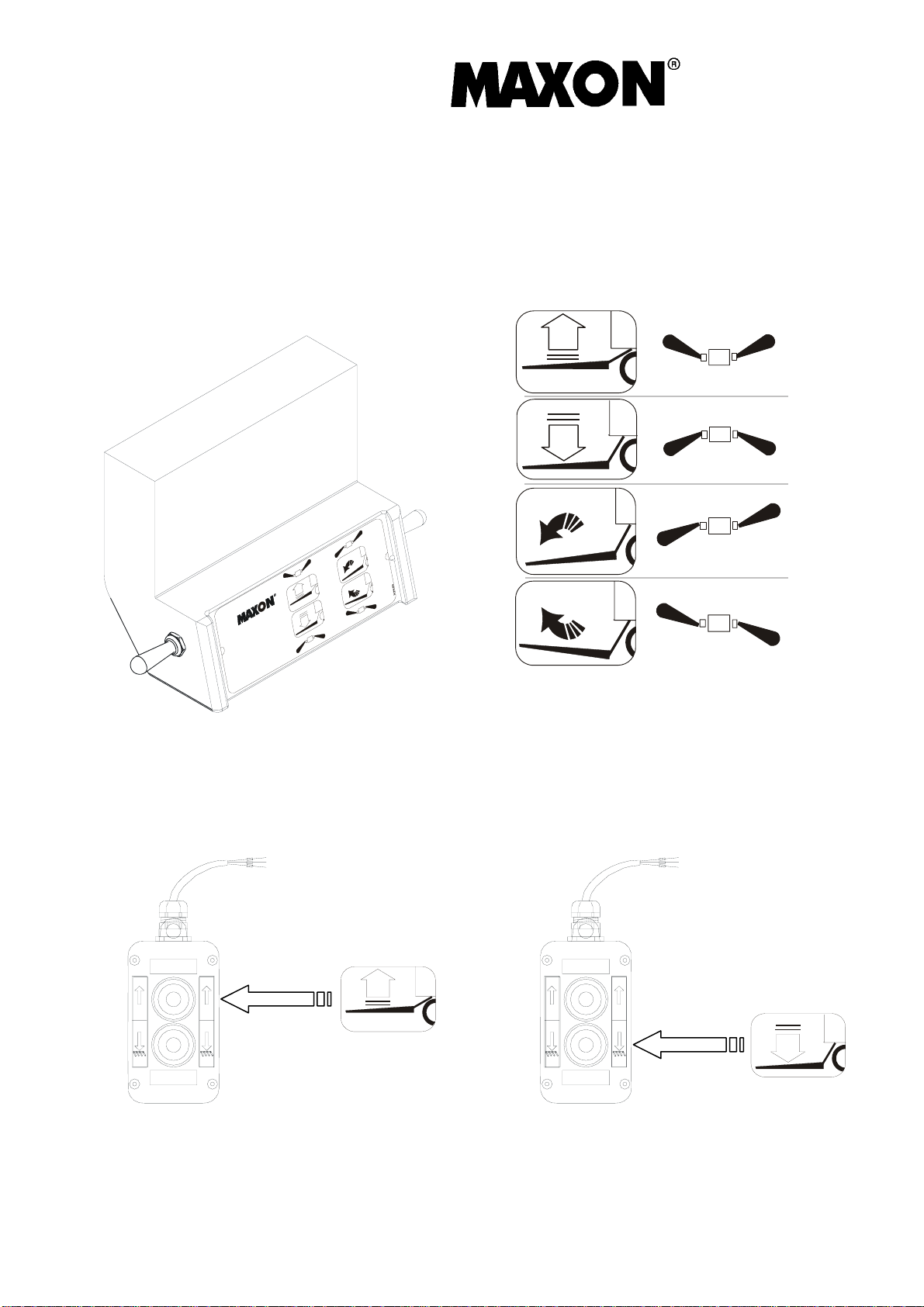
Description of the controls
Hand control box
All functions must be operated with two hands by switching the toggle switches located at the
side of the hand control
Hand control box 2 Buttons
box
Lift
Lower
Open / tilt down
Close / tilt up
Lift
Operator`s handbook
Document no.: S 20 909 946
Lower
3
Series GPC 22 X1
Version: 2011
Page 6
Lift CORP.
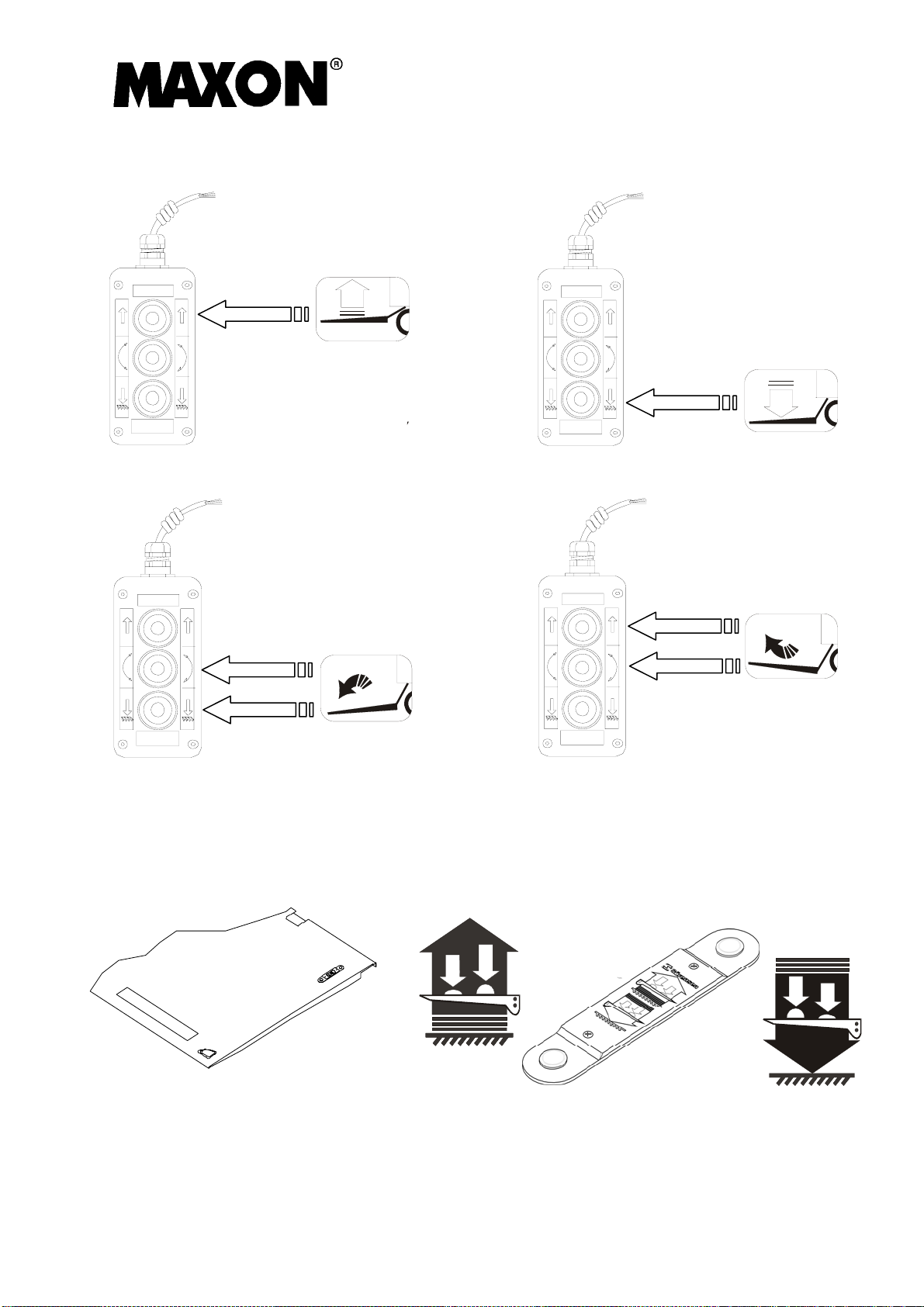
Hand control box 3 Buttons
Open / tilt down
Foot Controls (Optional version)
The foot controls are connected so that they only work when pushed in a specific order.
To lift and tilt up
Step 1 - activate foot control button for lowering
Step 2 - activate foot control button for lifting
Close / tilt up
Operator`s handbook
Document no.: S 20 909 946
To lower and tilt down
Step 1 - activate foot control button for lifting
Step 2 - activate foot control button for lowering
4
Series GPC 22 X1
Version: 2011
Page 7
Lift CORP.
General Information
Standing on the platform when it is moving
As it is only allowed for the operator to stand on the platform, he must ensure that no other
person (especially children) are standing inside the danger zone.
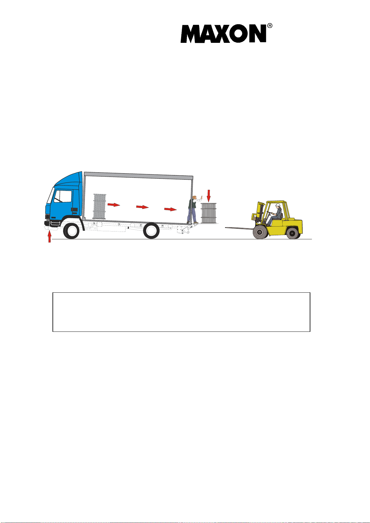
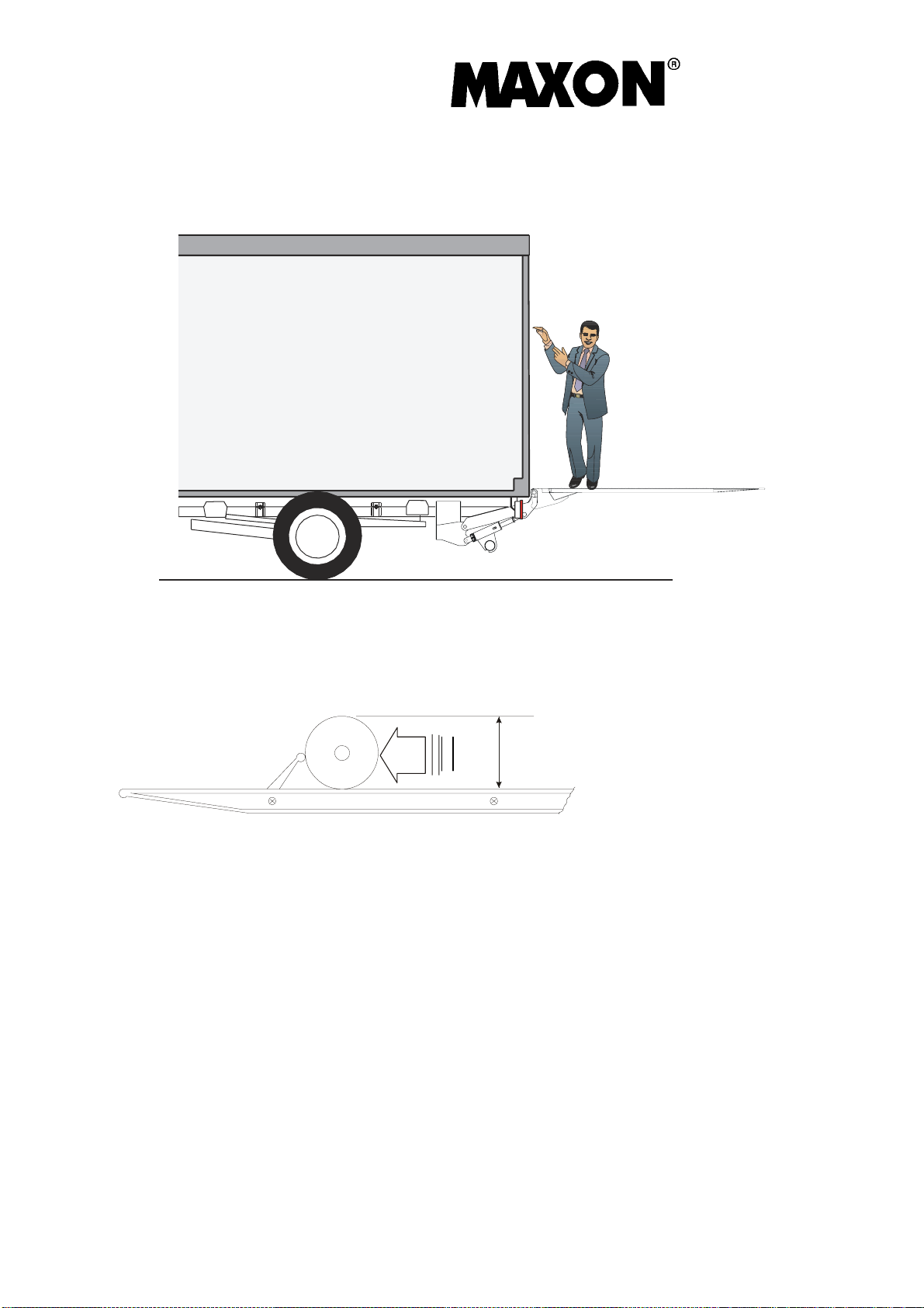
Hazard information for unsecured loads
Under certain circumstances, there is a possibility that the front axle of the vehicle lifts while
unloading. On this inclination, unsecure loads may start to slip and create a danger for the
operator.
You can purchase a warning sticker
CAUTION ! Secure the load against
moving or use mechanical supports
Operator`s handbook
Document no.: S 20 909 946
5
Series GPC 22 X1
Version: 2011
Page 8

Lift CORP.
Description of the Safety Installations
Hose Rupture Valves
If a hose, a pipe or a screw connection should burst, the lift gate lowers or inclines in a
controlled manner at the
permitted speed, as lon
control units (hand held remote controls, foot controls or hand control box). If such control
unit is not activated, or ceases to be activated, the lift gate stops automatically.
Safety Valve
The lift gate is protected by the factory-set safety valve from raising loads which are heavier
than the spe
ified carrying capacity. This valve may only be adjusted by an expert using a
c
test weight and a manometer.
Fuses
Defective fuses may only be replaced by fuses which correspond to the values specified in
the wiring diagram and on the distributor plate.
malfunctions, which could lead to cables catching fire.
Roll-off Safety Devices
If roller containers are being used, the lift gate should be equipped with roll-off safety
devices. Th
eir operation
is impaired by dirt; the operator should keep the roll-off safety
devices clean at all times.
Warning Flags
The flags can be seen until the platform is on the ground. Both safety installations should be
kept clean a
nd in perfect
condition at all times.
(Optional version)
Warning Lights
The lights flash as soon as the platform has opened a few degrees.
g as a function is connected via one of the
Larger fuses may not be
blown in the event of
Operator`s handbook
Document no.: S 20 909 946
6
Series GPC 22 X1
Version: 2011
Page 9
Lift CORP.
Standing on the platform when it is moving
When loading the platform, please ensure that you leave enough space for the operator to
securely operate the lift gate.
Securing of Loads
Rolling and sliding loads must be secured on the platform. Lift gates come optionally
equipped with cart stops, securing rolling loads with the maximum efficiency (wheels with
maximum diameter 4” )
Operator`s handbook
Document no.: S 20 909 946
7
Caster diameter max. 4“
Series GPC 22 X1
Version: 2011
Page 10

Lift CORP.
Safety guide for the operation of the lift gate
Secure the load against toppling over and sliding
Operator`s handbook
Document no.: S 20 909 946
8
Series GPC 22 X1
Version: 2011
Page 11

Lift CORP.
Permissible Loading
Apart from being included in these operating instructions, the load diagram is also shown on
the lift gate identification
nearest to the vehicle floor as possible, with the heaviest part of the load toward the vehicle.
No part of any load should be allowed to extend over the edges of the Platform. Do not place
unstable loads on the Platform. Do not allow any load to exceed the rated capacity for the
unit. If standing on the Platform, do not allow your feet to protrude beyond the edges. The
greater the distance of the load from the vehicle floor, the lower the loading capacity. The
maximum loading capacity specified in the load diagram must not be exceeded. The platform
may not be used with any load greater than the maximum permitted carrying capacity.
plate. All loads must be placed as close to the edge of the Platform
LBS
LBS
2500
2000
1500
1000
500
0
78 3/8 70 7/8 63 55 1/8 47 1/4 39 3/4 31 1/2 23 5/8 15 3/4 7 7/8
inch
The maximum weight indicated in the loading diagram must not be
exceeded. When the platform sits on the ground, it can be overrolled
only with the maximum load indicated.
GPC 22 X1
Operator`s handbook
Document no.: S 20 909 946
9
Series GPC 22 X1
Version: 2011
Page 12

Lift CORP.
Platform, bridge and ramp
Never sit the ramp on the platform, always use the platform as a ramp !
Operator`s handbook
Document no.: S 20 909 946
10
Series GPC 22 X1
Version: 2011
Page 13

Lift CORP.
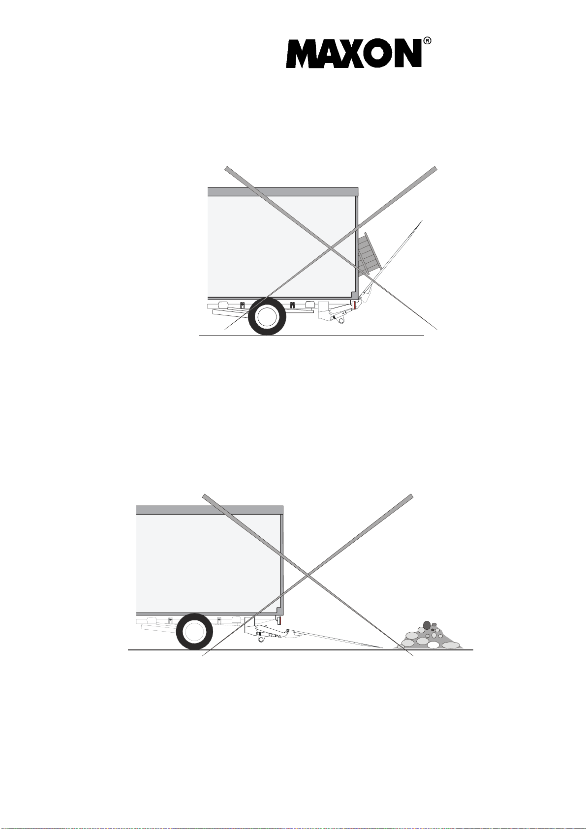
Load and unload at a ramp
Loading and unloading at a ramp is only possible if the platform tip sits firmly on the dock.
Please note
that the vehicle might lift
while unloading, and that the platform will lift from the
ground. To prevent accidents, the platform tilt must always be compensated, so that the tip
sits firmly on the dock at all times.
Operator`s handbook
Document no.: S 20 909 946
11
Series GPC 22 X1
Version: 2011
Page 14
Lift CORP.
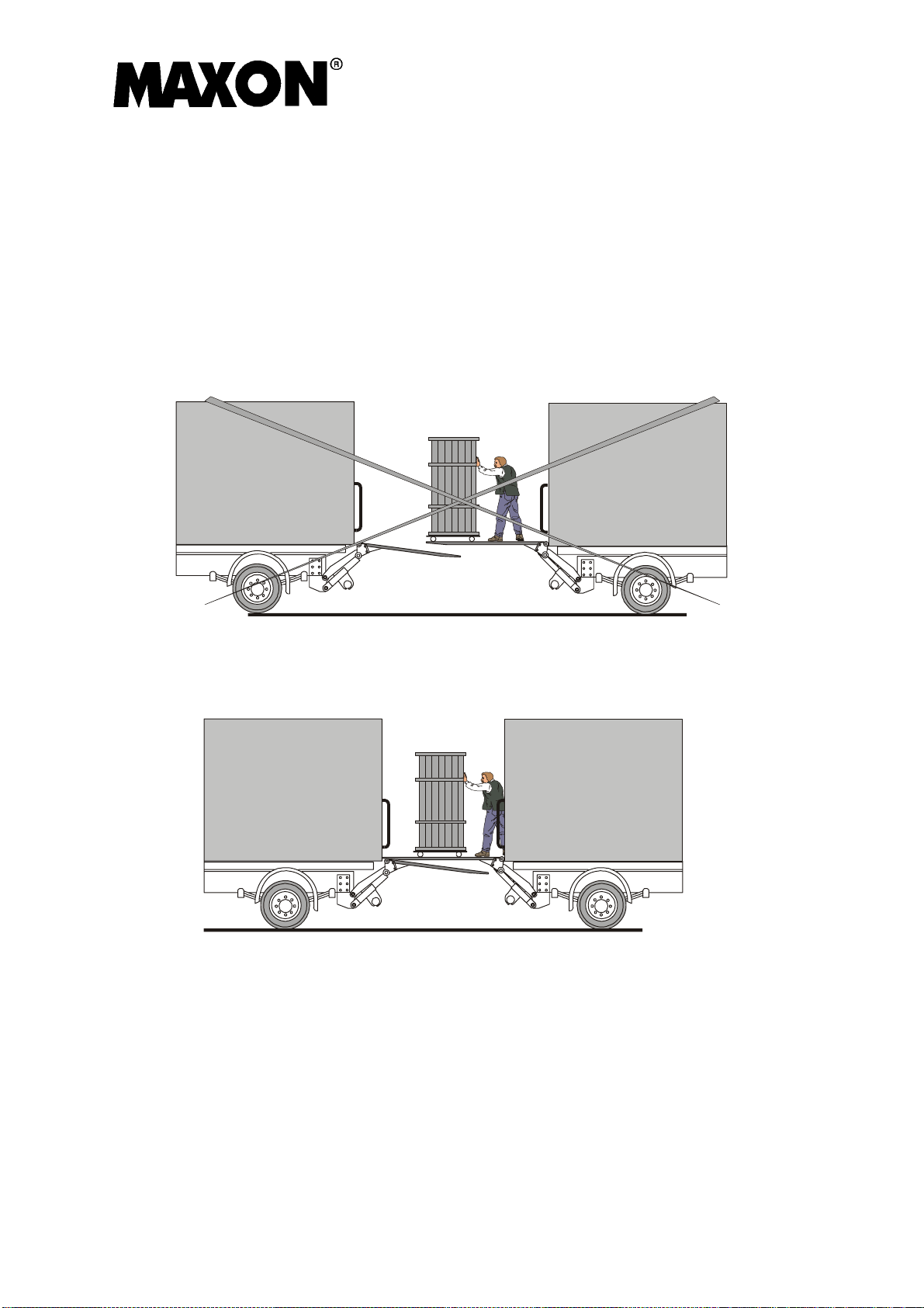
Transferring Loads from Vehicle to Vehicle
When transferring loads, it should be ensured that only one of the two platforms is being
used as a d
ock. The pla
or it may lead to the lift gate becoming overloaded.
tform being used as a dock must lie firmly on the vehicle opposite,
Wrong
Right
Operator`s handbook
Document no.: S 20 909 946
12
Series GPC 22 X1
Version: 2011
Page 15
Lift CORP.
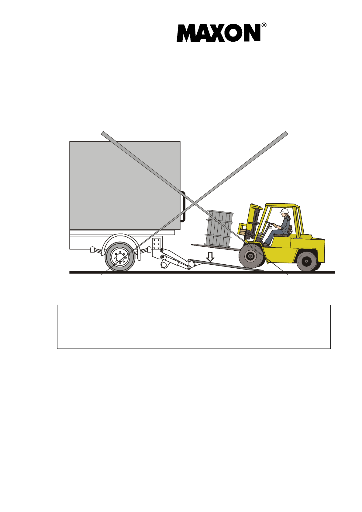
Loading with a Fork-Lift Truck
Driving over the platform with a fork-lift truck is not allowed if the weight of the fork-lift plus
the weight of the load to be transport
The platform must lie firmly on the floor.
ed is greater than the carrying capacity of the lift gate.
When performing any kind of loading or unloading
operation, the vehicle must be secured against
unexpected movement. Use handbrake or wedges
Operator`s handbook
Document no.: S 20 909 946
13
Series GPC 22 X1
Version: 2011
Page 16

Lift CORP.
Securing of Load
The use of the platform or any other parts of the lift gate as a means of securing a load is not
permitted.
Only close the platform after the lift arms have
circumstances close
the platform on the floor or in an intermediate position. This will destroy
cylinders, cables and mechanical parts.
moved firmly against the bodywork. Under no
Operator`s handbook
Document no.: S 20 909 946
14
Series GPC 22 X1
Version: 2011
Page 17
Lift gate as lifting device
Do not hand any loads on the platform
Lift gate as pushing device
Do not use the lift gate as a pushing device
Lift CORP.
Operator`s handbook
Document no.: S 20 909 946
15
Series GPC 22 X1
Version: 2011
Page 18

Lift CORP.
Care, Maintenance, Testing and Repairs
Before the start of maintenance work, the lift gate must be secured against unforeseen
movement.
The lift gate is very undemanding. It should, however, be included in the regular servicing
work on the vehicle.
Check that all screw connections are tight. Check that cables and hoses are able to move
freely. Corre
ct shearing
damaged hydraulic hoses with ones of the same quality. Note the replacement in the
inspection records.
During cleaning it should be ensured that no moisture penetrates the power pack or the
control box. The bearing
this may allow dirt and moisture to penetrate the bearing.
Check the hydraulic unit for leaks. With the lift gate lowered, check the oil level with the
platform lowered to the ground in th
The maximum oil level has been reached when the dipstick dips approx. one centimetre into
the oil.
Carry out an annual oil change and clean the suction filter. Carry out the oil change before
any period of frost, in ord
Hydraulic oil – recommendations
ISO 32 HYDRAULIC OIL ISO 15 HYDRAULIC OIL ISO-10 OR MIL-H-5606
Hydraulic Oil
AMSOIL AWH-05 AMSOIL AWF-05 AMSOIL N/A
CHEVRON HIPERSYN 32 CHEVRON FLUID A, AW-MV-
KENDALL GOLDEN MV KENDALL GLACIAL BLU KENDALL GLACIAL BLU
SHELL TELLUS T-32 SHELL TELLUS T-15 SHELL AEROSHELL FLUID-
EXXON UNIVIS N-32 EXXON UNIVIS HVI-1
MOBIL DTE-13M, DTE-24,
HYDRAULIC OIL-13
and chafing points on cables and hoses. Immediately replace
areas should not be cleaned with high pressure
or steam jets, as
e unit's tank (dipstick on the oil filler neck cover).
er to prevent the hydraulic unit from f
15
MOBIL DTE-11M MOBIL AERO HFA
reezing up.
CHEVRON FLUID A, FLUID G
41
EXXON UNIVIS HVI-13
With normal temperatures from 15 to 85 degree Fahrenheit it is recommended to use ISO 15
Hydraulic oil. For general colder climate use ISO 10, and warmer climate use ISO 32.
Oil fill up or change
1. lower
2. tilt down
3. oil fill up
1
3
Series GPC 22 X1
Version: 2011
Operator`s handbook
Document no.: S 20 909 946
2
16
Page 19

Lift CORP.
Repairs to Load-Bearing Components
Repairs to load-bearing components are only to be carried out in an authorized repair shop
and are to b
e tested by a competent person and
For any malfunctioning, first check voltage level
Troubleshooting
The 2 diodes in the front of the control box lits when the GPC
are switched on. If not
Problem possible cause
1. Motor of pump box
does not work
Battery cable or ground cable not connected or defective or
empty battery
Main fuse defective
Fuse in power pack defective
The power relay is defective and doesn't switch
Motor defective
2. Motor does not work
on one function only
Toggleswitch on hand control box defective
Cable from hand control box to pump box defective
entered in the inspection records.
- check the fuse in the battery cable.
Wiring inside pump box defective
Switch relay defective (Starter Solenoid)
3. Platform tilts down
alone without operating
Solenoid valves on tilting cylinder defective
Cylinder defective
that function.
4. Platform does not tilt
Cable to pressure switch defective
down when touching the
ground.
Pressure switch defective
5. Lift gate does not lift
Pump box does not work
Lack of oil in the tank
Voltage insufficient (low Battery)
6. Lift gate does not lift
Load is placed in excess of permitted loading distance
rated capacity
Weight of load too high
Overload security valve not set properly
Operator`s handbook
Document no.: S 20 909 946
17
Series GPC 22 X1
Version: 2011
Page 20

Lift CORP.
Voltage insufficient (low Battery)
7. Lift gate does not tilt up
from ground when unloaded
Mercury switch S2 defective or not set properly
Pump defective
Toggle switch does not operate
8. Lift gate does not tilt up
Load is placed in excess of permitted loading distance
from ground when loaded.
Weight of load too high
Overload security valve not set properly
9. Lift gate tilts from ground
Mercury switch S2 defective or not set properly
above horizontal
Where the electrical motor runs continuously (the lift gate will not switch off)
disconnect the positive cable from the battery b
y disconnecting the main switch or
throwing the main fuse.
In an emergency call our Customer Service Department or the nearest authorized repair
shop. On request, we shall be plea
sed to send
you an up-to-date list of Customer Service
repair shops authorised by us.
Operator`s handbook
Document no.: S 20 909 946
18
Series GPC 22 X1
Version: 2011
Page 21

Lift CORP.
In an Emergency
If, in an emergency, the lift gate is raised or closed manually or by mechanical means instead
of hydraulically, the hydraulic cylinders are
operational in this case. This means that removal of any rope, chain or other means being
used to hold lift in the raised position can be extremely dangerous and even fatal, as the lift
gate will freefall to the floor without any braking mechanism.
In such a case secure the lift gate by means of ropes or chains and attach a clear notice to it:
Caution ! Life danger ! The Lift gate is unsecured and must be operated
only by trained personnel !
Operation failure
In case of failure, please contact our customers service or the next authorized service dealer.
We will provide an up-to-date list of service dealers on request
Contact Maxon Technical Service at 1-800-227-4116 or by fax 888-771-7713
Warranty
LIFT CORP.
11921 Slauson Ave.
Santa Fe Springs, CA. 90670
CUSTOMER SERVICE:
(562) 464-0099
(800) 227-4116
FAX: (888) 771-7713
TECHNICAL SERVICE:
(800) 8-MAXTEK (862-9835)
WARRANTY POLICY & PROCEDURE
NEW LIFT GATE WARRANTY
Term of Warranty: 2 Years from Date of In-Service
Type of Warranty: Full Parts and Labor
MAXON agrees to replace any components which are found to be defective during the first
2 years of service, and will reimburse for labor based on Maxon’s Lift gate Warranty Flat
Rate
Labor Schedule.
All claims for warranty must be received within 30 Days of the repair date, and include the
following information:
1. Lift gate Model Number
2. Lift gate Serial Number
3. Description of Problem
4. Corrective Action Taken, and Date of Repair.
5. Parts used for Repair, Including MAXON Part Number(s).
6. MAXON R.G.A. # and/or Authorization # if applicable (see below).
7. Person contacted at MAXON if applicable.
PURCHASE PART WARRANTY
Term of Warranty: 1 Year from Date of Purchase Type of Warranty: Part Replacement and
Replacement Labor
MAXON will guarantee all returned genuine replacement parts upon receipt, and inspection
of parts and invoice. All Warranty repairs must be performed by an authorized MAXON
warranty station.
For major repairs, Maxon’s Warranty Department must be notified, and an “Authorization
filled with air. The safety valves are not
Operator`s handbook
Document no.: S 20 909 946
19
Series GPC 22 X1
Version: 2011
Page 22

Lift CORP.
Number” received. Major repairs would generally be considered repairs made to the
structural assembly of the lift gate and/or repairs not outlined in the Maxon Slidelift Waranty
Flat Rate Schedule.
Major components (i.e. hydraulic pumps, cylinders, valves, or failed structural parts) must
be returned, freight pre-paid, prior to the claim being processed. To ensure timely processing
of these warranty claims, an R.G.A. (Returned Goods Authorization) number must be
obtained from
Maxon’s Warranty Department prior to the return of any defective part. Defective Parts must
be returned within 60 da
Warranty Dapartment, MAXON Lift Corp.
16205 Distribution Way, Cerritos, California. 90703
Maxon’s warranty policy does not include the reimbursement for travel time; towing;
vehicle rental; service calls; fabrication of parts
due to misuse or abuse; loss of income due to downtime.
Maxon’s Flat Rate Labor Schedule times takes into consideration time required for diagnosis
of problem.
Warranty and Technical Information is available by calling Maxon’s Customer Service
Department.
NOTE:
Check with Customer Service Department for updat
annual basis.
Liability exclusions
Our liability excludes : damages assigned to wrong installation or operation of the slidelift,
overloading, unproper use, insuff
to ground contact (e.g. rough terrain at building sites)
ys of the claim date for consideration
which are a
to:
vailable from MAXON; oil; defects
ed versions of Manuals on an
nt battery charge or capacity, accidents or damages due
icie
Operator`s handbook
Document no.: S 20 909 946
20
Series GPC 22 X1
Version: 2011
Page 23

Decals
These Decals should be read and completely
understood before operating the unit. They should
also be kept clean and readable at all times. If
any decals should become detached from the
vehicles, or defaced, it must be replaced. Free
replacement are available from: MAXON Lift Corp.,
Parts Department.
Same distance bothsides
Ground level loaded
max. bed hight
GPC 22 X1 - max. bed hight 46” 7/16 - Liftarm 26” 9/16
min 17” 5/16
Ground level unloaded
Always as near max. as possible
max 26” 6/16
*
max 20” 1/16
min 32” 1/4 - inch
max 46” 7/16 - inch
Lift CORP.
Apply grease to bearings
located in arms prior
assembly
Caution!
Do not power pack
with hands, ropes or chains.
Do not use pry bars.
assemble o-rings
to arms as shown
lift on
Operator`s handbook
Document no.: S 20 909 946
21
Series GPC 22 X1
Version: 2011
Page 24

Lift CORP.
GPC 22 X1
THE MAXIMUM CAPACITY OF
THIS LIFT IS
2200 POUNDS
Diagnostic Lamp
Lift CORP.
11921 Slauson Avenue.
Santa Fe Springs, CA
90670
All liftgate warning, capacity, and caution decals
should be affixed to the truck body in plain view
of the operator near the main lift gate Control Station.
Note: The main liftgate Control Station is normally
mounted on right rear corner of the truck body.
®
Diagnostic Lamp
20 904 654
STAND CLEAR
WHEN OPERATING
WARNING
TIL T THE PLATFORM TO
LEVEL POSITION PRIOR
TO RAISING
50092
Improper operation of this Lift can result in serious personal injury. Do
not operate unless you have been properly instructed and have read, and
are familiar with the operat ing instructions. If you do not have a copy of
the instructions, please obtain them from your employer, distributor, or
lessor, before you attempt to operate Lift
Be certain that the vehicle is properly and securely braked beforeusing
the Lift
Always inspect this Lift for maintenance or damage before using it. If
there are signs of improper maintenance, damage to vital parts, or
slippery Platform surface, do not use the Lift until these problems have
been corrected
Do not overload the Lift. The load limit is based on evenly distributed
cargo over the entire Platform surface. If you are using a pallet jack, be
sure it can be maneuvered safely. Do not operate a forklift on the
Platform or travel with the platform in an open position at any time.
Load should be placed in a stable position close to the edge of the
Platform nearest the truck. The heaviest portion of the load should never
be placed beyond the center of the Platform away from the truck.
Never allow yourself, a helper, or bystander to stand in a position
where a falling load could land on either of you. Also do not allow any
part of yours or your helper body to be placed under, within, or around
any portion of the moving liftgate, or it`s mechanisms, or in a position
that would trap them between the platform and the ground or truck when
the liftgate is operated.
If a helper is riding the Platform with you, make sure you are both
doing so safely and that you are not in danger of coming in contact with
any moving or potentially moving obstacles. USE GOOD COMMON
SENSE. If load appears to be unsafe, do not lift or lower it.
MAXON LIFT CORP.
WARNING
READ CAREFULLY
PART NO.
264081
Operator`s handbook
Document no.: S 20 909 946
22
Series GPC 22 X1
Version: 2011
Page 25

Page 26

X
X
XXXX
XX
X
X
YA
KM
X
X
*
S4S2S1
Y3
Y1
XX
X
XX
X
X
X
Y1
KM
Th
SERVICE-SWITCH
KM
Y1
YA
31
YA
30
YA
KM
30
Y3
Y3
Y1
KM
30
YA
Y1
Y3
31
30
DATUM:
control-unit
gez.:
No.:
W.Bassen SOE28050
29.01.2008
20 908 356
gr/ye
123 6 5
No 30
20 905 547
20 906 387
20 905 109
X
250 cm
test up,down
lamp +
lamp +
test S2,S4
HANDHELD CONTROLBOX
DOWN
UP
CONTROL-LAMP
20 907 162 CONTROL-UNIT 12 V
30 - batteryplus
31 - batteryminus
KM - motorrelay
YA - solenoid in power-pack
Y1 - solenoid tilt-cylinder
Y3 - solenoid lift-cylinder
S1 - mercury-switch
S2 - mercury-switch lift
S4 - pressure-switch tilt down
Th - motor-thermoswtich
ON/OFF - Switch
POWER-PACK
FUSE 6A
motor-relay
FUSE 250 A
Please connect behind
the fuse
platform-cable
tilt-cylinder
TILT-DOWN
LOWER
TILT-UP
LIFT
TILT DOWN
TILT-UP
LOWER
LIFT
HANDHELD
CONTROL CONTROLBOX
right lamp is out, if switch "up" or "down" is pressed on handheld
controlbox.
left lamp is out also, if "down" is pressed and
S4 switched if platform is on ground (lift-cylinder is without pressure).
left lamp is out, if "up" is pressed and
S2 switched at horizontal platform position.
STANDARD 12V GPC 22 X1
OPTION:
®
TILT
white (30)
brown (+)
red (30)
blue
viol.
green
1 - 1 - S4
2 - 2 - S4
3 - 3 - Y3
4 - gr/ge - Y3
1 -
2 - brown - S2
3 -
4 - black - S2
5 - grey - S1
6 - gr/ye - S1
Hg - switch
S1 + S2
mercury
S1
grey
gr/ye
S2
black
brown
platform
1 - 1 - +
2 - 2 - FH
3 - 3 - FS
4 - 4 - S2
5 - 5 - S1
6 - gr/ye - 31
plug no.
cable no.
signal
Y3
P
S4
lift-cylinder
pressure-
swtich
blue
brown
1
23
gr/ye
plug no.
cable no.
1 - 1 - 30
2 - 2 - YA
3 - 3 - KM
4 - 5 - Y1
5 - 6 - Y3
6 -gr/ye - 31
plug no.
cable no.
7G1.5
grey
blue
gr/ye
brown
+
31
1
2
3
gr/ye
black
cable no.
cable color.
red
blue
grey
U
T
D
brown
450 cm 7G0.75
60 cm 4G0.75
60 cm 7G1.5
120 cm 5G0.75
50 cm FLKK
*S1 signal is lead to ground
22 905 768 REPLACEMENT
Page 27

Page 28

Page 29

 Loading...