

Maxon FRS-114 Owner's Manual
FRS-114
Family Radio Service
UHF Two-Way Radio
OWNER'S MANUAL
English/Spanish

TABLE OF CONTENTS
FRS Product Description 1
Package Contents 2
Controls and Functions 3
Programming Instructions 6
Operating Instructions 8
Charging Ni-Cad Batteries 10
Specifications 11
Warranty Service Instructions 12
Warranty Statement 13
Maxon Accessories 15
Other Maxon Products 15

TABLA DE CONTENIDO
Controles y Funciones 3
FRS Descripción del Producto 16
Contenido del Paquete 17
Instrucciones de Programación 18
Instrucciones de Operación 20
Para Cargar Baterías Ni-Cad 22
Especificaciones 23
Instrucciones Servicio
de Garantía 24
Aclaración de la Garantía 25
Accesorios Maxon 27
Otros Productos Maxon 27

FRS PRODUCT DESCRIPTION
The Family Radio Service (FRS) is the newest
generation in personal two-way communications. FRS radios operate in a license-free
band (no FCC license for operation) on one of
14 license-free channels.
Maxon's FRS-114 is a lightweight, palmsized two-way radio that you can carry
almost anywhere. Use it at shopping malls,
sporting events, amusement parks... any
indoor or outdoor activity! The radio
communicates up to 2 miles* - allowing you
to keep in touch with family, friends or a
neighborhood watch group.
The FRS-114 is a single channel model
with the capability of all 14 FRS channels.
You can talk to another person using any
FRS radio, provided that you are on the
same frequency. Channel programming
is described in this manual.
The radio has an automatic battery saver
feature -- at 8 seconds of non-use the radio
goes into power save, assuring longer battery
life.
* Range will vary, depending on terrain and environment.
1

PACKAGE CONTENTS
FRS-114 Radio with Belt Clip
Screw-in "Rubber Duck" Antenna
Owner's Manual
2

3
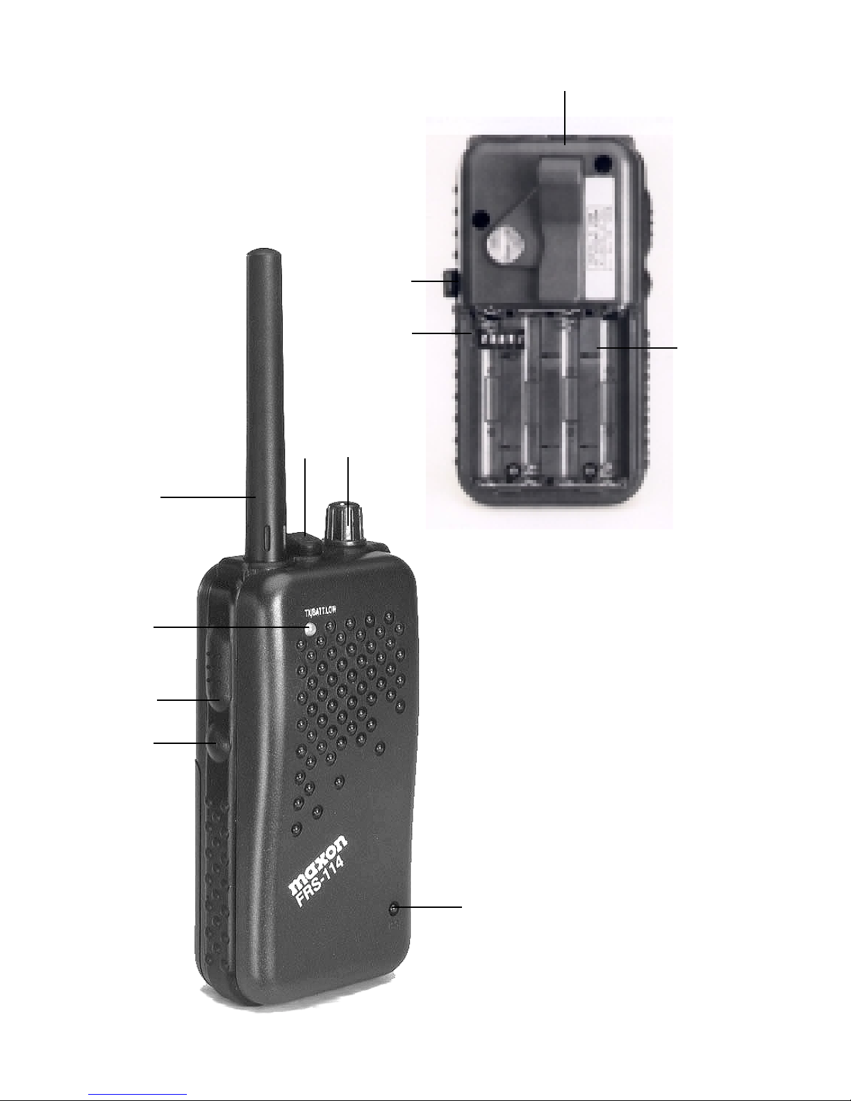
CONTROLS AND FUNCTIONS
CONTROLES Y FUNCIONES
A. Monitor Button - Checks activity on the channel,
and permits the radio to monitor weak signals
• Botón de Monitoreo - Observa la actividad en el
canal y permite al radio monitorear las señales
débiles
B. Push-To-Talk Button - Permits radio transmissions
• Botón "Presione Para Hablar" (P-T-T) - Permite la
transmisión por radio
C. Transmit/Battery Low LED - Indicates active
transmissions and alerts user to low battery condition
• LED Muestra Transmisión/ Batería Baja - Indica
transmisiónes activas y alerta al usuario cuando la
batería tiene carga baja
D. Antenna • Antena
E. Ear Speaker Jack - Used with an ear speaker for
private audio reception • Conector de Microfóno
Para Oido - Se usa para recepcion privada de audio
F. Off/On-Volume Control - Used to turn the radio on
or off and adjust the listening volume • Control de
Volúmen - Se usa para encender o apagar el radio y
para ajustar el volúmen
G. Microphone - Transmits voice signals • Microfóno -
Transmite señal de voz
H. Channel Programming Dip Switches - Used to
program the radio channel frequency (located within
battery compartment) • Programacion de Canels via
Interruptor - Se usa para programar la frecuencia de
canales en el radio (localizado a un lado de
compartimento para baterías)
4
E F
D
C
B
A
G
J
I
H
K

5
I. Charge Jack - Used to charge ni-cad batteries inside
the unit - requires optional Maxon DV-7510 AC/DC
wall charger (located on side of unit) • Conector
Para Cargador - Se usa para cargar baterías ni-cad de
ntro de la unidad. Se requiere el modelo opcional
Maxon DV-7510 AC/DC cargador de pared
(localizado en la parte trasera de la unidad)
J. Belt Clip - Used to secure the radio to a belt, or
another convenient location • Grapa de Centurón -
Se usa para llevar el radio en el cinturón o en
cualquier otra parte conveniente
K. Battery Compartment - Houses 4 AAA size batteries
(located on back of unit) • Compartimento para
Baterías - Contiene 4 baterías AAA (localizado en la
parte trasera de la unidad)

6
PROGRAMMING INSTRUCTIONS
Remove the battery compartment door.
BEFORE INSTALLING BATTERIES, locate
the channel programming dip switches at
the upper left corner. To select an operating
channel, move the switches per the chart
below (we suggest you use a pointed utensil
like a ball point pen). All radios must be on
the same frequency to communicate with
each other. NOTE: Switch 5 is not used in
programming.
Example of dip switches set for Channel 9:
Switch: 1/down 2/down 3/down 4/up
Channel 1* - Frequency 462.5625 MHz
Switch: 1/up 2/up 3/up 4/up
Channel 1* - Frequency 462.5625 MHz
Switch: 1/down 2/up 3/up 4/up
Channel 1* - Frequency 462.5625 MHz
Switch: 1/down 2/down 3/down 4/down
*NOTE: There are three combinations for Channel
1, any can be used.
1 2 3 4 5

7
Channel 2 - Frequency 462.5875 MHz
Switch: 1/up 2/down 3/down 4/down
Channel 3 - Frequency 462.6125 MHz
Switch: 1/down 2/up 3/down 4/down
Channel 4 - Frequency 462.6375 MHz
Switch: 1/up 2/up 3/down 4/down
Channel 5 - Frequency 462.6625 MHz
Switch: 1/down 2/down 3 /up 4/down
Channel 6 - Frequency 462.6875 MHz
Switch: 1/up 2/down 3/up 4/down
Channel 7 - Frequency 462.7125 MHz
Switch: 1/down 2/up 3/up 4/down
Channel 8 - Frequency 467.5625 MHz
Switch: 1/up 2/up 3/up 4/down
Channel 9 - Frequency 467.5875 MHz
Switch: 1/down 2/down 3/down 4/up
Channel 10 - Frequency 467.6125 MHz
Switch: 1/up 2/down 3/down 4/up
Channel 11 - Frequency 467.6375 MHz
Switch: 1/down 2/up 3/down 4/up
Channel 12 - Frequency 467.6625 MHz
Switch: 1/up 2/up 3/down 4/up
Channel 13 - Frequency 467.6875 MHz
Switch: 1/down 2/down 3/up 4/up
Channel 14 - Frequency 467.7125 MHz
Switch: 1/up 2/down 3/up 4/up
 Loading...