

Page 1
Model EP-4800
EDACS ®/ GE-MARC®
TRUNKING PORTABLE
Operating
Instructions
Page 2

TABLE OF CONTENTS
Safety Information 1
Battery Care 1
Recycling/Disposal of Batteries 2
Battery Charging 2
Extended Operations 3
FCC Licensing 4
Transceiver Service 4
Introduction 5
Radio Call-outs 6
Features 7
Quick Reference Guide - Controls 8
Quick Reference Guide - Indicators 10
System, Group and Channel Indicators 10
Alert Tones - Standard 11
Alert Tones - Trunked Operation 12
Error Messages 14
Keypad Lock 14
Keypad Mute 14
SCAT Operation 15
EDACS Operation
Receiving a Message 15
Sending a Message 16
Squelch Adjustment 17
Sending a Special Call 17
Sending a Manually Entered Call 18
Storing Individual/Interconnect Numbers 20
Recalling Individual/Interconnect Numbers 21
DTMF Overdial 22
Scan Operation
Enable/Disable Scan 22
Add/Delete Scan List Groups 23
Home Key 23
Page 3

TABLE OF CONTENTS, Continued
GE-MARC Operation
Receiving a Message 24
Sending a Message 25
Sending a Special Call 25
Sending a Pre-Programmed Special
(In Conference Call) 27
Sending a Manually Entered Call 28
Storing Individual/Interconnect Numbers 30
Recalling Individual/Interconnect Numbers 31
Wide Area System Scan 33
Direct Mode Operation
Receiving A Message 34
Sending A Message 34
Sending A Manually Entered Interconnect Call 35
Scan Operation
Enable/Disable 35
Add/Delete Channels 36
Conventional Operation
Receiving a Message 37
Sending a Message 37
Squelch Adjustment 38
Sending a Manually Entered Interconnect Call 38
Scan Operation
Enable/Disable 39
Add/Delete Channels 39
Warranty Statement Inside Back Cover
EDACS and GE-MARC are registered
tradenames of Ericsson Inc.
Page 4

SAFETY INFORMATION
The Federal Communications Commission (FCC), with its action in
General Docket 79-144, dated March 13, 1985, has adopted a safety
standard for the human exposure to radio frequency (RF) electromagnetic energy emitted by FCC regulated equipment. Proper
operation of this radio will result in user exposure far below the
Occupational Safety and Health Act and Federal Communications
Commission limits.
WARNING - DO NOT hold the radio in such a manner that the
antenna is close to, or touching, exposed parts of
the body - especially the eyes or face - while the
radio is transmitting.
WARNING - DO NOT allow children to operate transmitter-
equipped radio equipment.
CAUTION - DO NOT operate the radio near unshielded electrical
blasting caps or in an explosive atmosphere, unless
it is a type specifically designed and qualified for such
use.
CAUTION - DO NOT operate the radio unless the antenna connector
is secure and any open connectors are properly
terminated.
This device complies with Part 15 of the FCC Rules. Operation is
subject to the condition that this device does not cause harmful
interference.
BATTERY CARE
WARNING
DO NOT dispose of the battery pack in fire - it may explode,
causing injury or death.
DO NOT replace the battery in hazardous atmosphere locations.
DO NOT carry a battery loose in your pocket or purse.
DO NOT attempt to repair battery.
1
!
!
!
!
Page 5

RECYCLING/DISPOSAL OF BATTERIES
The U.S. Environmental Protection Agency (EPA) classifies used
Ni-Cd batteries as hazardous waste, unless certain exemptions apply.
The battery should be recycled at the end of its useful life. Under
various state or local laws, such batteries must be recycled or disposed
of properly and cannot be dumped in landfills or incinerators.
Maxon America, Inc. fully endorses and encourages the recycling of
Ni-Cd batteries. A national program to collect and recycle used Ni-Cd
batteries is being implemented by the Rechargeable Battery Recycling
Corporation (RBRC™). This program is being funded through the use of
license fees paid by the battery and product manufacturers to place the
RBRC™ Seal on the batteries.
The following is a list of facilities where the batteries can be shipped to
be recycled. Contact these facilities for proper packaging and shipping
guidelines.
INMETCO Kinsbursky Brothers Inc.
245 Portersville Road 1314 N. Lemon Street
Ellwood City, PA 16117 Anaheim, CA 92801
TEL: (412) 758-2800 TEL: (714) 738-8516
FAX: (412) 758-2842 FAX: (714) 441-0857
(800) 548-8797
BATTERY CHARGING
Your radio comes supplied with a 7.5 volt 1100 mAh Ni-Cd battery
pack, which can be recharged from 500 to 1000 times before it
requires replacement. The actual number of charge/recharge cycles
vary depending upon usage. We recommend that the battery be
charged 14 to 16 hours on the first charge cycle, then according to
the charger model instructions thereafter.
To remove the battery pack, push up on the battery latch and slide
the battery pack to the right. To replace the battery, align the battery
on the track and slide to the left until a click is heard, indicating the
battery is correctly installed.
If the battery is to be charged on the radio, ensure that the power
2
Page 6

BATTERY CHARGING, Continued
switch on the radio is in the off position before charging. Failing to
turn the power switch to off during the charge cycle will result in a
less-than-full charge condition, which will noticeably reduce the radio
operating time between charges!
Normal battery operation time is 8 hours. This may vary depending
upon how much the receiver audio is present and how much you
transmit. The actual time may vary from day to day depending upon
operational requirements.
For best performance:
• Charge battery to full capacity, 14 hours at the standard C/10 rate
(capacity x .10). For "rapid" chargers, allow additional time (2-3 hours)
for "topping off" the charge after it switches from "fast" to "slow" mode.
• Use the battery soon and use as much of the battery capacity
as possible or practical. A battery that is charged and discharged
completely will maintain the longest running time capacity. Also,
several charge/discharge cycles are recommended to bring a new
battery up to its rated capacity.
• Store and charge the batteries at room temperature (65o to 75o F).
Batteries that have been stored for over a month should be recharged
before being put into service (due to chemical self-discharge which
occurs at a rate of approximately 1% per day). Do not charge cold
batteries (40o F or below).
• Reduced capacity or "memory effect" may result from repeated
identical shallow discharge/full recharge cycles. If such a condition
is suspected, run the battery until the radio loses all power, then fully
recharge and discharge again. Repeat this cycle 3-4 times.
EXTENDED OPERATIONS
When operating in "fringe areas" at some distance from the System,
the other party may not receive your transmission clearly. Also you
may notice that the background noise will increase on received
signals. Moving to higher ground or moving closer the System will
help alleviate these problems. If moving closer to the System is not
3
Page 7

EXTENDED OPERATIONS, Continued
practical, communication may be improved by moving away from
shielding structures. If you are in a building interior, move closer to
a window (preferably one generally in the direction of the System).
At 800 MHz, the wave length is very short - sometimes moving a
few inches to a few feet can make significant signal strength changes.
Finding the best location can also be done while listening to the background noise when moving about; attempt to find a spot where the
background noise is reduced to a minimum or eliminated entirely.
This may make the difference from not being heard, to being heard
loud and clear when operating in the fringe areas of your System
coverage. The fringe distance will vary greatly from plains areas,
hilly terrain and mountain top sites.
FCC LICENSING
This unit may or may not require a specific FCC license to operate.
The FCC requires all transmitters in the conventional and some trunked
Systems to be licensed by the Federal Communications Commission.
Some trunked operations now are exempt from individual licensing
requirements but must be operated in a licensed System.
Consult your Dealer regarding specific licensing information, or
contact the Federal Communications Commission.
For more information regarding Form 571 (FCC License Application)
call 717-337-1212 or contact the FCC District Office near you.
TRANSCEIVER SERVICE
There are no user serviceable components inside the radio. Altering
the internal components or adjustments may result in illegal emissions,
including off-frequency operation, or damage to the radio. Should an
UNLOCK condition be shown in the LCD window, or the LCD fail to
display information, or all icons and display segments be shown, turn
the On/ Off- Volume control OFF then ON to reset the microprocessor.
Ensure that the battery is fully charged and check that the antenna is
securely tightened. If the unit still fails to operate properly, refer to an
Authorized Service Center for servicing.
4
Page 8

INTRODUCTION
The Maxon EP-4800 Series EDACS Trunking Portable Radio provides
reliable trunked communication in the 800 MHz band. Advanced
dual format technology allows the radio to operate within the EDACS
Trunked System and the GE-MARC Trunked System. The radio will
also operate in a Conventional System.
The unit is lightweight and easy to carry. A backlit alphanumeric
display provides clear visibility for low light or night-time operation.
This manual provides a separate section of operating instructions for
each of the 3 systems (EDACS, GE-MARC, and Conventional). The
Description section (which follows) and the Battery Information are
applicable to all users.
NOTE: This radio allows the operator to switch between an EDACS,
a GE-MARC and a Conventional system. Special attention should be
given to the System selected and the operating characteristics of the
radio while working within that System.
5
Page 9
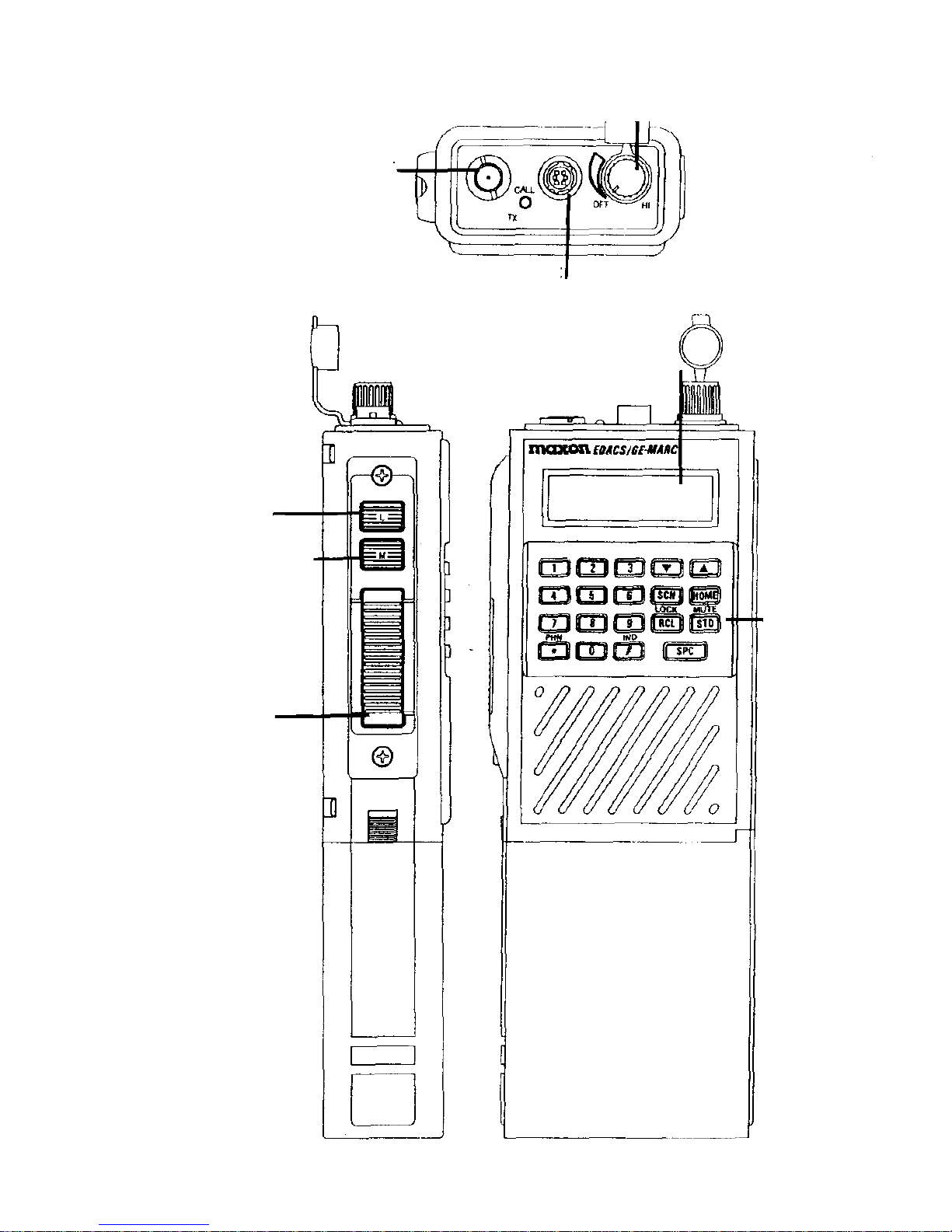
RADIO CALL-OUTS
6
Keypad
Antenna Connector
On/Off- Volume Control
Ext. Speaker/Mic
Connector
LCD Window
Backlight
Shift/Clear/Monitor
PTT Button
Page 10

FEATURES
• Up to 16 Systems selectable with up to 16 Groups per System
(EDACS)
• Up to 9 Areas x 9 Groups (GE-MARC)
• System scan
• System lockout when scanning
• Group Scan automatically or manually
• First Available System Scan when out of range of Systems
• 7-character alphanumeric LCD display with backlight for
System and Group identification and other status information
• Operation in both Trunked and Conventional modes
• Repeater talkaround in Conventional and Trunked modes
• Standard keypad for placing telephone interconnect calls
• Call indicator
• User-programmable storage of up to 10 telephone numbers
and up to 10 individual numbers of up to 14 digits in length
• Automatic System ringback if System is busy
• Transmit inhibit with busy tone
• Clear-to-talk tone signals when speaking can begin
NOTE: System setup determines the specific operation of some of
the above features. Refer to the descriptions in this manual for more
information.
7
Page 11
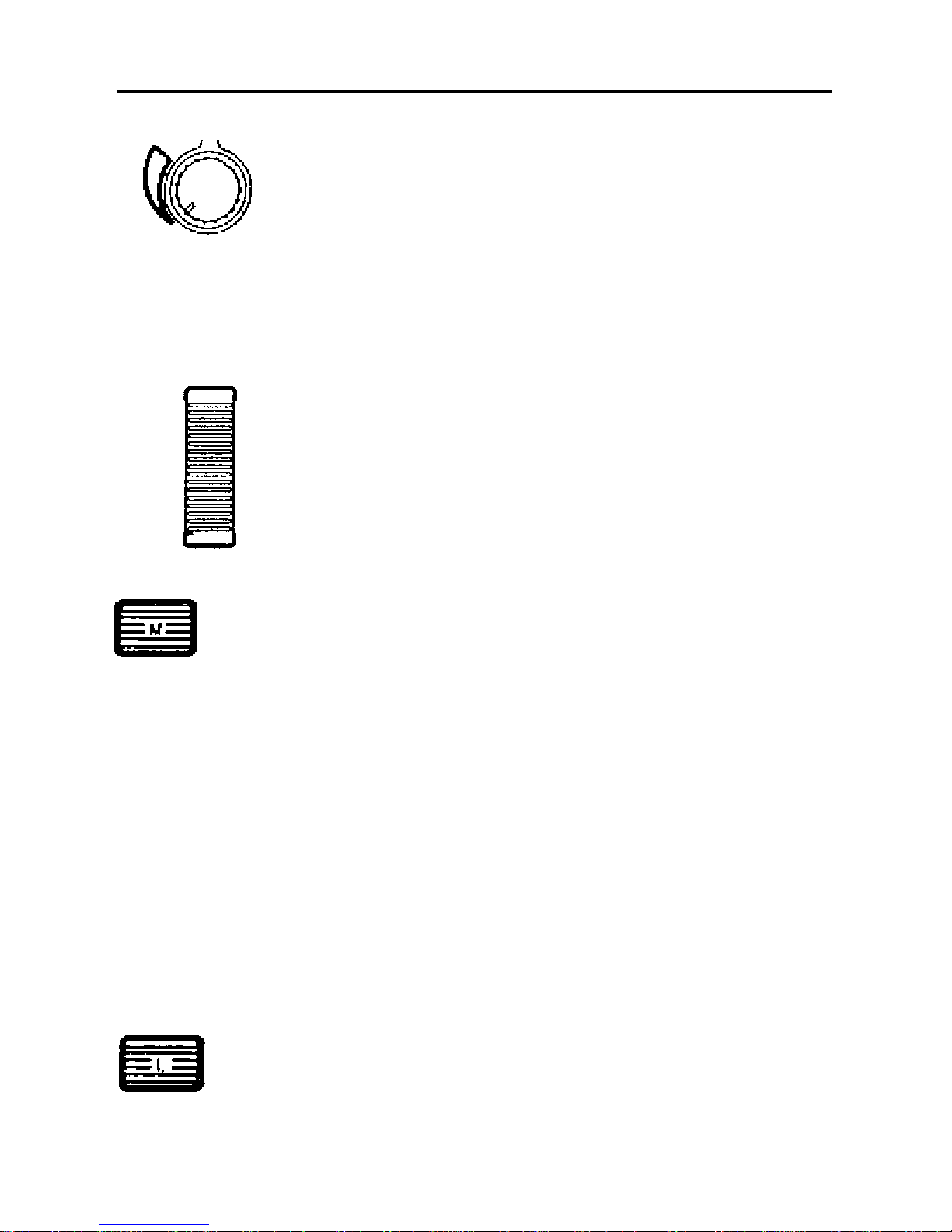
QUICK REFERENCE GUIDE - CONTROLS
Clockwise rotation provides power (with a
mechanical click sound). Continued rotation
increases volume level. Counter-clockwise
rotation decreases volume. Full counter-clock
wise rotation removes power (a click sound
will be heard at full detent). The radio can
be programmed to beep once after power
is applied, indicating it is ready for use.
PTT (Push To Talk) Pressing the PTT button (located on the side of
the radio) will key the radio's transmitter and
perform the necessary steps to acquire a
communication channel.
Shift / Clear/ Monitor All alternate key functions are accessed by
pressing this button and then pressing the
desired function key.
Trunked - Pressing this button twice will
enable the CLEAR function (used to exit the
Special Call mode and return to the normal
System / Group display).
Conventional - Pressing and holding this
button twice (double click) will enable the
MONITORING mode (checking the channel
for activity by unsquelching the receiver). All
transmissions will be heard, even if Channel
Guard protected.
Backlight Pressing this button illuminates the LCD for a
pre-programmed time period.
On/Off- Volume
OFF HI
8
Page 12

QUICK REFERENCE GUIDE - CONTROLS, Continued
System/Group The ! and " buttons are used to select
Select Group/Channel numbers. Pressing the radio's
Shift/Clear/Monitor button and then the up or
down arrows will select the System. These
up/ddown arrow buttons are also used in the
Special Call mode (trunked systems only).
HOME Pressing and holding this key for a
programmed duration selects a desired
Group and / or System.
SPC (Special) Pressing this key will put the radio in the
Special Call mode. The radio will be able
to make individual and interconnect calls
(trunked systems only).
SCN This key is used to enable the Scan mode and
(Scan Add/ Delete) add to or delete Groups/Channels to the scan
list.
STO (Store) Pressing this key stores individual call
numbers and interconnect calls (trunked
systems only).
MUTE Pressing the STO key in combination with the
(Duplex function of Shift/Clear /Monitor button will mute/ unmute
the STO key) the radio.
RCL (Recall) Pressing this key will recall manually entered
individual and interconnect calls in EDACS
and GE-MARC systems.
LOCK Pressing the RCL key in combination with
(Duplex function of the Shift /Clear/Monitor button will lock the
the RCL key) keypad. All buttons and keys will be locked
except PTT, HOME, Shift/Clear /Monitor, and
LOCK.
9
!
"
Page 13
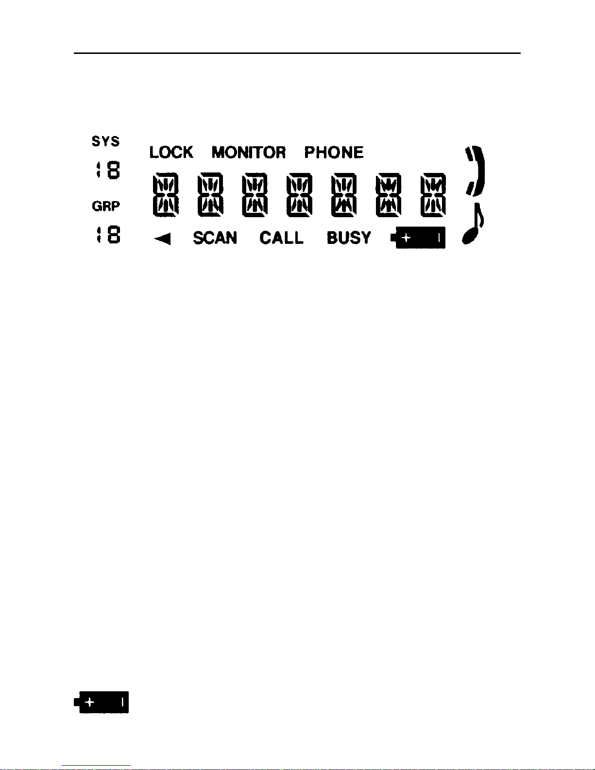
QUICK REFERENCE GUIDE - INDICATORS
The EP-4800 radio has a 7-character alphanumeric display that
identifies the selected System/Group, operating modes or error
conditions. The display uses 12 status indicators, described on the
following pages.
The LCD backlight can be programmed to turn on anytime the "L"
(backlight button) is pressed or any button or key is pressed. It will
remain on for a programmable length of time, and is programmed
on a per Group / Channel basis. You may also choose to have the
backlight programmed to remain off at all times or to remain on
(or off) when the PTT button is pressed.
SYSTEM, GROUP AND CHANNEL INDICATORS
SYS (System) This display identifies the number of the
current EDACS, GE-MARC or Conventional
System selected.
GRP (Group) This display identifies the number of the
current Group in an EDACS or GE-MARC
System. The indicator disappears when radio
operates in a Conventional System, but the
channel number will show on display.
STATUS INDICATORS
BUSY This display indicates the radio has received
a call or a conventional channel is in use. The
indicator is also shown when transmitting on
a trunked channel.
This icon is shown when radio battery power
is low and needs charging.
10
Page 14

QUICK REFERENCE GUIDE - INDICATORS, Continued
SCAN This display appears when Scan is activated.
LOCK This display appears when the keypad lock
function is enabled.
This icon indicates that a trunked Group or
Conventional channel is scan enabled.
PHONE In EDACS or GE-MARC modes, a display and
handset icon will be shown when the radio is
placed in the Special Call mode.
CALL This display appears when the radio receives
an individual call in EDACS or GE-MARC
modes.
This icon indicates that the key press tones are
activated.
MONITOR This display appears with the monitor mode
has been enabled in a Conventional System.
NC (No Connect) This display appears when the radio has no
connection within the service area.
ALERT TONES - STANDARD
The radio generates a number of tones to indicate radio status and
condition. Both standard tones and those generated during trunked
operation are described on the following pages.
Power-Up If programmed, a tone will sound upon power
up, after the radio passes the self test.
Low Battery A low pitched tone will sound every 130
seconds when the battery is low and needs
charging.
11
Page 15

ALERT TONES - STANDARD, Continued
Carrier Control The Carrier Control Timer (CTT) alert is a
Timer pulsed tone signal that sounds whenever the
PTT button is continuously pressed for a preprogrammed length of time. After nine (9)
seconds of signalling, the transmitter shuts
down and communication is interrupted. To
maintain communication, release and re-key
the PTT switch. This resets the timer and turns
the transmitter back on. The CCT is a built-in
precaution against inadvertent use of the
system.
ALERT TONES - TRUNKED OPERATION
Call Originate EDACS - If programmed, a short tone is
sounded whenever the PTT button is keyed
and the radio has acquired a channel. This
tone indicates the user may proceed to talk.
GE-MARC - If programmed, a three-tone alert
is sounded whenever the PTT button is keyed
and the radio has acquired a channel. These
tones indicate the user may proceed to talk.
Call Received If programmed, a single alert tone sounds
when a group call is received. A two-tone
alert (one high followed by one low tone) is
sounded for an individual call.
Call Queued EDACS - If one short, high pitched tone sounds
after the transmitter is keyed, this indicates that
the System has placed the request in a queue.
The tone sounds at both the transmitting unit
and the receiving unit(s), indicating to the user
on the receiving end that they will receive a
call shortly. If the PTT is unkeyed while in the
queue, the radio will autokey (automatically
key the PTT) when a channel is available.
12
Page 16

ALERT TONES - TRUNKED OPERATION, Continued
Autokey EDACS - When the PTT is keyed to place a
call on the System, but the PTT is released
before getting to the channel (e.g. a queued
call), the radio will automatically key on the
channel when it gets the assignment. The
radio generates a long beep and holds the
transmitter keyed for two seconds. Pressing
the PTT button keeps the channel and sends
the message before this two second time-out
has expired.
System Busy EDACS - If you key the PTT button and hear
three short, medium-pitched tones, they
indicate that the receiving party is already
engaged in another call or the system is busy
and its queue is full. You must rekey later to
access the System.
GE-MARC - If you key the PTT button and
hear a low frequency tone for 1 second, this
indicates all channels are busy.
Call Denied EDACS - A single low-pitched beep will sound
when the PTT button is keyed and the request
is denied by the System. This happens if the
unit is an invalid user or is requesting an
unavailable service.
Out of Range/System EDACS - A single pitched tone will sound
immediately after the PTT button is keyed,
indicating the radio is out of range of the
repeater. The radio tries to place the call
for a short period (3 seconds) after the initial
attempt. The radio generates a second low
pitched tone when it gives up trying to place
the call. The system is off the air or the radio
needs servicing when the radio is within
calling range, and these tones are heard.
13
Page 17

ALERT TONES - TRUNKED OPERATION, Continued
Out of Range/System, GE-MARC - Five beeps will sound shortly
Continued after the PTT button is keyed if the radio is
out of range of the repeater or inoperative.
If the "call retry" is active, the radio will try
the channel at twenty (20) second intervals
for five minutes.
ERROR MESSAGES
SYN LOC If at anytime the synthesizer is unable to load
(Synthesizer Lock) and lock on the channel properly, this display
will be shown. If a SYN LOC message is
displayed on all Systems, the radio has failed
or has not been programmed properly. The
radio buttons and keys will still operate.
PRS ERR If the personality has not been programmed
(Personality Error) into the radio, this display will appear.
KEYPAD LOCK
The keypad can be locked at any time to prevent any undesired key
presses. To lock the keypad when it is in the unlocked state, press the
RCL key (LOCK) in combination with the Shift/Clear/ Monitor button.
All buttons and keys except the PTT, HOME, SHIFT/CLR /MONITOR
and LOCK will now be inhibited. To unlock the keypad when it is in
the locked state, press the RCL key (combined with the Shift/Clear/
Monitor button) and release.
KEYPAD MUTE
The keypad can be muted at anytime. To mute the keypad when it is
in the unmute state, press the STO key (MUTE) in combination with
the Shift/Clear /Monitor button. All buttons will be muted. To unmute
the keypad, press the STO key (combined with the Shift/Clear/
Monitor button) and release. The keypad is now unmuted.
14
Page 18

SCAT OPERATION
A SCAT (Single Channel Autonomous Trunking) System operates
with the same set of features as a standard EDACS system. The only
user change relates to the BUSY indicator. Since only one channel,
operating as both control and working channel, exists in a SCAT
System, the BUSY indicator will be on when the SCAT channel is
in the working channel mode. When the transmission on the channel
is completed, the indicator turns off and indicates the return of SCAT
control channel signaling.
~ EDACS Operation ~
RECEIVING A MESSAGE
1. Turn the radio on by rotating the On/ Off-Volume control clockwise from the off (detent) position. After the radio has passed the
power-up self test, an optional tone will sound and the current
System and Group will be displayed. If the radio fails the self test,
an error message will be displayed or the display will be blank.
See Error Messages section.
2. Press the M (Shift/ Clr/ Monitor) button and then use the up/down
arrow buttons to select an EDACS System. The SYS (System)
display will indicate the current System selected. Press the M
(Shift/Clr/Monitor) button again to exit System select.
3. Use the up/down arrow buttons to select the desired Group.
The GRP (Group) display will indicate the current Group selected.
The radio is now ready to receive messages.
4. Using the Volume control knob, adjust the volume as necessary.
INDIVIDUAL CALL - If an individual call (a call directed only to your
radio) is received, the radio unsquelches on the assigned channel.
The BUSY indicator will display. If programmed on, the individual
call received tones (one high followed by one low) will sound and
the originator's ID or just "ID" (depending upon programming) is
displayed for a short time. To answer the call, simply press PTT and
begin talking if the caller's ID is still shown. If caller's ID is no longer
shown, press the SPC key to return the caller's ID to the display, then
press PTT and begin talking.
15
Page 19

EDACS - RECEIVING A MESSAGE, Continued
GROUP CALL - When the radio receives a Group call, it unsquelches
on the assigned channel and lights the BUSY indicator. If programmed
on, the Group call received tone (single tone) will sound. The radio
can also be programmed to display the Group name originator's ID.
INTERCONNECT CALL - If an interconnect call (a telephone call
directed to your radio) is received, the radio unsquelches on the
assigned channel. The radio displays PHN CAL and the CALL and
BUSY indicators appear. If programmed on, the interconnect call
received tones (one high followed by one low) will sound. PHONE
and the handset icon will be displayed.
NOTE: The optional call received tones are programmed OFF by
default.
SENDING A MESSAGE
1. Turn the radio on, select and set the desired System and Group as
described under previous section, EDACS - Receiving A Message.
2. Observe the display - the BUSY and the NC (No Connect)
indicators should not be present, confirming that no one is
transmitting on the selected Group, and that the radio is in
a service area.
3. Press and hold the PTT button. The radio will perform the
signaling required to obtain a communication channel. If the
signaling is unsuccessful, the radio will sound the appropriate
alert tone(s). Refer to Alert Tones - Trunking Operation section.
4. When the channel has been acquired, the red TX (transmit) LED
(on radio's top panel) and the BUSY indicator will illuminate. If
programmed, the call originate tone (single short tone) will sound.
5. Hold the radio about 3 inches from your mouth and speak in a
normal tone into the microphone.
6. Release the PTT button when your transmission is complete and
listen for a reply.
16
Page 20

EDACS - SQUELCH ADJUSTMENT
In normal operation, the squelch is automatically set by the radio and
does not need adjusting. If it becomes necessary to adjust the squelch,
use the following procedure:
Press and hold the M (Shift/ Clr/ Monitor) button. Use the up/down
arrow buttons to adjust the squelch - up arrow opens the squelch;
down arrow closes the squelch.
NOTE: The radio must be on a Conventional System or an EDACS
working Channel (i.e. receiving a voice call) to adjust the squelch.
It is recommended that you adjust squelch from a Conventional
System.
SENDING A SPECIAL CALL
1. Press the SPC (special) key to put the radio into Special Call
mode and provide access to an alphanumeric special call list.
Each selection from the list is pre-programmed with either an
individual number or an interconnect number. If programmed,
the special call alphanumeric identifier will be displayed. The
PHONE and handset icon will be displayed while in the Special
Call mode.
2. Press the up/down arrow keys to move through the special call list.
NOTE: To display the last seven digits of the individual interconnect
number currently selected, press and hold the M (Shift/Clr /Monitor)
button and then press the SPC (special) key.
INDIVIDUAL CALL - Once the desired individual special call number
is displayed, press and hold the PTT to initiate the call. The radio will
perform the required signaling to obtain a working channel.
When the signaling is successfully completed, the BUSY display
will appear and the call originate tone sounds. Speak directly into
the microphone. Release the PTT button as soon as you stop talking
and wait for a reply.
When the call is complete, double click the M (Shift/ Clr/ Monitor)
17
Page 21

EDACS - SENDING A SPECIAL CALL, Continued
button to exit the Special Call mode and return to the normal
System/Group display.
INTERCONNECT - Once the desired interconnect special number
is displayed, press and hold the PTT to initiate the call. The radio
will perform the required signaling to obtain a working channel.
When the signaling is successfully completed, the BUSY display
will appear, and the proper DTMF tones will be sent and heard at
the speaker. When someone answers, press the PTT button and speak
directly into the microphone. Release the PTT button as soon as you
stop talking. Messages cannot be received when the PTT button is
pressed. If the signaling is unsuccessful, the radio will remain in the
Special Call mode and sound the appropriate alert tone(s).
When the call is complete, double click the M (Shift/ Clr/ Monitor)
button to exit the Special Call mode and return to the normal System/
Group display.
SENDING A MANUALLY ENTERED CALL
INDIVIDUAL CALL
1. Press the SPC (special) key to put the radio into Special Call mode.
The display will identify the last accessed Special Call name /
number from the pre-programmed Special Call list. PHONE and
the handset icon will be displayed while in the Special Call mode.
2. Enter the ID number of the radio to be called. The last digit
entered will always be displayed in the far right hand side of
the display. Any previously entered digits will scroll to the left.
Only the last seven characters will be visible in the display - the
leading character will scroll off the display with each new entry.
To backspace and clear a digit, press the SCN (scan) key.
NOTE: To recall the last individual number entered manually from the
keypad, press the RCL (recall) key.
3. Press and hold the PTT button to initiate the call. The radio will
perform the required signaling to obtain a working channel.
18
Page 22

EDACS - INDIVIDUAL CALL, Continued
4. When the signaling is successfully completed, the BUSY indicator
will appear, and the call originate tone sounds. Speak directly into
the microphone. Release the PTT button as soon as you stop talking
and wait for a reply. Messages cannot be received when the PTT
button is pressed. If the signaling is unsuccessful, the radio will
remain in the Special Call mode and sound the appropriate alert
tone(s).
5. When the call is complete, double click the M (Shift/ Clr / Monitor)
button to exit the Special Call mode and return to the normal
System / Group display.
INTERCONNECT CALL
1. Press the SPC (special) key to put the radio into Special Call mode.
The radio will display the last accessed call number from the preprogrammed Special Call list. The PHONE and handset icon will
be displayed while in the Special Call mode.
2. Enter the telephone number to be called. The last digit entered
will always be displayed in the far right hand side of the display.
Any previously entered digits will scroll left. Only the last seven
characters will be visible in the display - the leading character
will scroll off the display with each new entry. To backspace and
clear a digit, press the SCN (scan) key.
NOTE: To recall the last interconnect number entered manually from
the keypad, press the RCL (recall) key.
3. Complete the telephone entry by pressing the * key, indicating
that the digits are for an interconnect call. The * will not be
displayed, but a tone will sound.
4. Press and release the PTT button to initiate the call. The radio
will perform the required signaling to obtain a working channel.
When the signaling is successfully completed, the BUSY indicator
will appear and the proper DTMF tones will be sent and heard at
the speaker. If the interconnect signaling is unsuccessful, the radio
will remain in the Special Call Mode and sound the appropriate
alert tone(s).
19
Page 23

EDACS - INTERCONNECT CALL, Continued
5. When someone answers, press the PTT button and speak directly
into the microphone. Release the PTT button as soon as you stop
talking. Messages cannot be received when the PTT bar is pressed.
6. When the call is complete, double click the M (Shift/ Clr / Monitor)
button to exit the Special Call mode and return to the normal
System / Group display.
STORING INDIVIDUAL/ INTERCONNECT NUMBERS
NOTE: Use the # key for storing manual individual calls; the * key for
storing manual interconnect calls as follows:
1. Press the SPC (special) key to put the radio into Special Call mode.
The display will identify the last accessed call number from the
pre-programmed Special Call list. PHONE and the handset icon
will be displayed while in the Special Call mode.
2. Enter the ID number or telephone number of the radio to be
stored. The last digit entered will always be displayed in the far
right hand side of the display. Any previously entered digits will
scroll left. Only the last seven characters will be visible in the
display - the leading character will scroll off the display with
each new entry. To backspace and clear a digit, press the SCN
(scan) key.
3. Complete the entry by pressing the # key for individual
numbers and the * key for telephone interconnect numbers.
The # key indicates the digits entered are for an individual call
and * key indicates the digits are for an interconnect call. They
will not be displayed but a tone will sound.
4. Enter a digit between 0 and 9 to select a storage location. The
storage location will not be displayed, but a tone will sound.
There are 10 storage locations for individual numbers and 10
storage locations for interconnect numbers. Press the STO (store)
key to complete the storage procedure.
5. Double click the M (Shift/Clr/Monitor) button to exit the Special
Call mode and return to the normal System / Group display.
20
Page 24

RECALLING INDIVIDUAL/INTERCONNECT NUMBERS
NOTE: Use the # key for recalling and placing an individual call; the
* key for recalling and placing an interconnect call as follows:
1. Press the # key to recall the individual call list or the * key
to recall the interconnect call list. The screen will blank and a
tone will sound.
2. Enter the desired storage location number (0-9).
3. Press the RCL (recall) key to put the radio into the Special Call
mode. If the number is from the individual call list, the ID number
will be displayed. If the number is from the interconnect call list,
the last seven digits of the telephone number will be displayed.
If the memory location is blank, the radio will sound a low pitched
tone after the RCL (recall) key is pressed.
INDIVIDUAL - Once the desired individual call number is displayed,
press and hold the PTT button to initiate the call. The radio will
perform the required signaling to obtain a working channel.
When the signaling is successfully completed the BUSY indicator will
appear, the red TX (transmit) LED will illuminate and the Call Originate
tone will sound. Speak directly into the microphone. Release the PTT
button as soon as you stop talking and wait for a reply. If the signaling
is unsuccessful, the radio will remain in the Special Call mode and
sound the appropriate alert tone(s).
When the call is complete, double click the M (Shift/ Clr/ Monitor)
button to exit the Special Call mode and return to the normal System/
Group display.
INTERCONNECT - Once the desired interconnect special call number
is displayed, press and release the PTT button to initiate the call. The
radio will perform the required signaling to obtain a working channel.
When the signaling is successfully completed, the BUSY indicator
will appear, and the proper DTMF tones will be sent and heard at
the speaker. When someone answers, press the PTT button and speak
directly into the microphone. Release the PTT as soon as you stop
21
Page 25

EDACS - RECALLING NUMBERS, Continued
talking. Messages cannot be received when the PTT button is pressed.
If the signaling is unsuccessful, the radio will remain in the Special
Call mode and sound the appropriate alert tone(s).
When the call is complete, double click the M (Shift/ Clr/ Monitor)
button to exit the Special Call mode and return to the normal System/
Group display.
EDACS SPECIAL CALL KEYPRESS REFERENCE
(INDIVIDUAL CALLS)
To Place: SPC key -- DIGITS -- PTT
To Store: SPC key -- DIGITS -- # key -- 0-9 -- STO key
To Recall and Place: # key -- 0-9 -- RCL key -- PTT
(INTERCONNECT CALLS)
To Place: SPC key -- DIGITS -- * key -- PTT
To Store: SPC key -- DIGITS -- * key -- 0- 9 -- STO key
To Recall and Place: * key -- 0-9 -- RCL key -- PTT
DTMF OVERDIAL
After the radio has acquired a working channel, if programmed, to
make a message trunked call, DTMF tones can be sent by pressing
and holding the PTT button and manually enter the desired numbers
using the keypad.
In the same manner, stored interconnect numbers (tones) may be sent
by recalling the desired storage location as described previously in the
Recalling Manually Stored Individual/Interconnect Numbers section.
Press the PTT button to send the tones.
SCAN OPERATION
ENABLE/DISABLE SCAN
To enable Group scanning, press the SCN (scan) key. The SCAN
identifier will display to indicate scan is active. To disable scan, press
the SCN (scan) key. The SCAN identifier will disappear to confirm scan
function is off.
22
Page 26

EDACS - SCAN OPERATION, Continued
ADD/DELETE SCAN LIST GROUPS
Groups can be added or deleted from the scan list as necessary.
Adding Groups:
1. Select the desired Group to be added. If the current Group is
already included in the scan list, the left arrow icon will display.
2. To add the Group to the scan list, press the M (Shift/ Clr/ Monitor)
button and then the SCN (scan) key. The left arrow icon will
display, and the group will be added to the scan list.
NOTE: Scan must be disabled to add a Group to the scan list.
Deleting Groups:
1. Select the desired Group to be deleted. If the current Group is
already included in the scan list, the left arrow icon will display.
2. To delete the Group from the scan list, press the M (Shift/ Clr/
Monitor) button and then the SCN (scan) key. The left arrow icon
will disappear, and the group will be removed from the scan list.
HOME KEY
The radio can be programmed to automatically switch to a home
System and/or Group by pressing and holding the HOME key for
the programmed duration.
If the HOME key is enabled, the radio will switch to the programmed
home System and/or Group. When HOME is disabled, it is not active.
~End of EDACS Operation Section~
~Beginning of GE-MARC Operating Section~
23
Page 27

~ GE-MARC Operation ~
RECEIVING A MESSAGE
1. Turn the radio on by rotating the On/Off-Volume control clockwise from the off (detent) position. After the radio has passed the
power-up self test, an optional tone will sound and the current
System and Channel will be displayed. If the unit fails the self test,
an error message will be displayed, or the display will be blank.
See Error Messages section.
2. Press the M (Shift/ Clr/Monitor) button and then use the up/down
arrow buttons to select a GE-MARC system. The SYS (System)
display will indicate the current System selected.
3. Use the up/down arrow buttons to select the desired Group.
The GRP (Group) display will indicate the current Group selected.
The radio is now ready to receive messages.
4. Using the Volume control knob, adjust the volume as necessary.
INDIVIDUAL CALL - If an individual call (a call directed only to your
radio) is received, the radio unsquelches on the assigned channel.
The BUSY indicator and *INDV* (individual call) will display, and
the individual call received tones (one high followed by one low
tone) will sound unless programmed off.
GROUP CALL - When the radio receives a group call, it unsquelches
on the assigned channel and displays the BUSY indicator. The Group
call received tone (single tone) will sound unless programmed off.
INTERCONNECT CALL - If an interconnect call (a telephone call
directed to your radio) is received, the radio unsquelches on the
assigned channel and the BUSY indicator appears, along with
PHN CAL on the display. If the received tone set was the selected
Group tone set, then the radio will operate as it does when it
receives a Group call from another radio. If the tone set was the
selected System's individual call tone set, the radio will operate as
if it had received an individual call from another radio.
24
Page 28

SENDING A MESSAGE
1. Turn the radio on, select and set the desired System and Group
as described under previous section, GE-MARC - Receiving A
Message.
2. Observe the display - the BUSY should not be present, confirming
that no one is transmitting on the selected Group.
3. Press and release the PTT bar. The display will show "WAIT"
while the radio performs the required signaling to obtain a
communication channel. If the signaling is unsuccessful, the radio
is out of range or inoperative, "NO SERV" will appear on the
display, and a sequence of five beeps will be heard at the speaker.
Any subsequent attempt to initiate a call within the next 20 seconds
will be ignored.
If all available repeaters are busy when the call is attempted,
one long beep is heard, and BUSY is displayed. The call will not
be retried automatically.
NOTE: If the "call retry" option is active, the radio will display
"RETRYNG" and try the channel at twenty (20) second intervals for
five minutes before returning to the normal System / Group display.
4. When the channel has been acquired, the BUSY indicator will
appear and, if programmed, the call originate tones (a three-tone
alert) will be heard from the speaker.
5. Press the PTT button. The red TX (transmit) LED will illuminate.
Hold the radio about three inches from your mouth and speak
in a normal tone into the microphone.
6. Release the PTT button when the transmission is complete and
listen for a reply.
SENDING A SPECIAL CALL
1. Press the SPC (special) key to put the radio into Special Call mode
which also provides access to a pre-programmed special call list.
Each selection from the list is programmed with either anindividual
25
Page 29

GE-MARC - SENDING A SPECIAL CALL, Continued
number or an interconnect number. If programmed, the special
call list is capable of displaying an alphanumeric field. The PHONE
and handset icon will be displayed while in the Special Call mode.
If no special calls are programmed, the radio displays "SPC CAL".
2. Press the up/down arrow keys to move through the special call list.
NOTE: To display the last seven digits of the individual or interconnect
number currently selected, press and hold the M (Shift/Clr/Monitor)
button and then press the SPC (special) key.
INDIVIDUAL CALL - Once the desired individual special number
is displayed, press and release the PTT button to initiate the call. The
display will show "WAIT" while the radio performs the necessary
signaling required to obtain a working channel.
When the signaling is successfully completed, the BUSY display will
appear and the call originate tones (a three-tone alert) will be heard at
the speaker. Press the PTT bar and speak directly into the microphone.
Release the PTT bar as soon as you stop talking and wait for a reply.
When the call is complete, double click the M (Shift/ Clr/ Monitor)
button to exit the special call mode and return to the normal System /
Group display.
INTERCONNECT CALL - Once the desired interconnect special call
number is displayed, press and release the PTT to initiate the call.
The display will show "WAIT" while the radio performs the necessary
signaling required to obtain a working channel.
When the signaling is successfully completed, the BUSY display
will appear and the proper DTMF tones will be sent and heard at
the speaker. When someone answers, press the PTT bar and speak
directly into the microphone. Release the PTT bar as soon as you
stop talking and wait for a reply.
If the signaling is unsuccessful, the radio is out of range or inoperative,
"NO SERV" will appear on the display, and a sequence of five beeps
will be heard at the speaker. Any subsequent attempt to initiate a call
26
Page 30

GE-MARC - SENDING A SPECIAL CALL, Continued
within the next 20 seconds will be ignored.
If all available repeaters are busy when the call is attempted, one long
beep is heard, and BUSY is displayed. The call will not be retried
automatically.
NOTE: If the "call retry" option is active, the radio will display
"RETRYNG" and try the channel at twenty (20) second intervals for
five minutes before returning to the normal System / Group display.
When the call is complete, double click the M (Shift/ Clr/ Monitor)
button to exit the special call mode and return to the normal System /
Group display.
The radio is capable of the following from the Special Call mode:
• Storing and/or recalling up to 10 individual and 10 interconnect
numbers in 2 separate storage locations. These numbers are
manually entered from the keypad.
• Initiating individual and interconnect calls that are manually
entered from the keypad.
Each of the features are discussed in detail in the following sections.
SENDING A PRE-PROGRAMMED SPECIAL CALL
(IN CONFERENCE CALL)
Pre-programmed special calls can also be initiated using the selected
group tone set. To initiate a special call in Conference Call mode, press
key 7 to put the radio into Conference Call mode. If programmed,
the special call list is capable of displaying an alphanumeric field. If
no special calls are programmed, the radio displays "CNF CAL".
The programmed call may now be sent following the procedure
described in SENDING A SPECIAL CALL section.
27
Page 31

SENDING A MANUALLY ENTERED INDIVIDUAL CALL
INDIVIDUAL CALL
1. Press the SPC (special) key to put the radio into Special Call mode
or key 7 to put the radio into Conference Call mode. The radio
displays the last accessed special call number from the preprogrammed special call selection. PHONE and the handset icon
will be displayed. If no special calls are programmed, the radio
displays "SPC CAL".
2. Enter the tone set of the radio to be called. The last digit entered
will always be displayed in the far right hand side of the display.
Any previously entered digits will scroll to the left. Only the last
seven digits will be visible in the display - the leading digit will
scroll off the display with each new entry. To backspace and clear
a digit, press the SCN (scan) key.
NOTE: To recall the last individual number entered manually from the
keypad, press the RCL (recall) key.
3. Press and release the PTT bar to initiate the call. The display will
show "WAIT" while the radio performs the signaling required to
obtain a working channel.
4. When the signaling is successfully completed, the BUSY display
will appear and the the proper DTMF tones will be sent and heard
at the speaker. When someone answers, press the PTT bar and
speak directly into the microphone. Release the PTT bar as soon
as you stop talking and wait for a reply.
If the signaling is unsuccessful, the radio is out of range or inoperative,
"NO SERV" will appear on the display, and a sequence of five beeps
will be heard at the speaker. Any subsequent attempt to initiate a call
within the next 20 seconds will be ignored. The radio can be cleared
from this mode by double clicking the M (Shift/Clr/ Monitor) button.
If all available channels are busy when the call is attempted, a one
second beep is heard, and BUSY is displayed. The call will not be
retried automatically.
NOTE: If the "call retry" option is active, the radio will display
28
Page 32

MANUALLY ENTERED INDIVIDUAL CALL, Continued
"RETRYNG" and try the channel at twenty second intervals for five
minutes before returning to the normal System/Group display.
5. When the call is complete, double click the M (Shift/Clr/Monitor)
button to exit the Special Call or Conference Call mode(s) and
return to the normal System/Group display.
INTERCONNECT CALL
1. Press the SPC (special) key to put the radio into Special Call mode,
or key 7 to put the radio into Conference Call mode. The radio
displays the last accessed special call number from the preprogrammed special call selection. PHONE and the handset icon
will show on the display. If no special calls are programmed, the
radio displays "SPC CAL".
2. Enter the telephone number to be called. The last digit entered
will always be displayed in the far right hand side of the display.
Any previously entered digits will scroll to the left. Only the last
seven digits will be visible in the display - the leading digit will
scroll off the display with each new entry. To backspace and
clear a digit, press the SCN (scan) key.
NOTE: To recall the last interconnect number entered manually from
the keypad, press the RCL (recall) key.
3. Complete the telephone entry by pressing the * key. The * key
indicates the digits are for an interconnect call. This will not be
displayed but a tone will sound.
4. Press and release the PTT bar to initiate the call. The display will
show "WAIT" while the radio performs the necessary signaling
required to obtain a working channel. When the signaling is
successfully completed, the BUSY display will appear and the
proper DTMF tones will be sent and heard at the speaker. When
someone answers, press the PTT bar and speak directly into the
microphone. Release the PTT bar as soon as you stop talking and
wait for a reply.
29
Page 33

GE-MARC - MANUALLY ENTERED CALL, Continued
If the signaling is unsuccessful, the radio is out of range or inoperative,
"NO SERV" will appear on the display, and a sequence of five beeps
will be heard at the speaker. Any subsequent attempt to initiate a call
within the next 20 seconds will be ignored. The radio can be cleared
from this mode by double clicking the M (Shift/Clr/ Monitor) button.
All channels are busy when the signaling is unsuccessful and a one
second low frequency tone is heard at the speaker. The call will not
be retried automatically.
NOTE: If the "call retry" option is active, the radio will try the channel
at twenty second intervals for five minutes before returning to the
normal System / Group display.
5. When the call is complete, double click the M (Shift/Clr/Monitor)
button to exit the Special Call mode and return to the normal
System/Group display.
STORING INDIVIDUAL/ INTERCONNECT NUMBERS
1. Press SPC (special) key to put the radio into Special Call mode,
or key 7 to put the radio into Conference Call mode. The radio
displays the last accessed call number from the pre-programmed
special call selection. PHONE and the telephone handset icon
will display. If no special calls are programmed, the radio displays
"SPC CAL".
2. Enter the tone set (individual call) or telephone number to be
stored. The last digit entered will always be displayed in the far
right hand side of the display. Any previously entered digits will
scroll to the left. Only seven digits will be visible in the display the leading digit will scroll off the display with each new key
entry. To backspace and clear a digit, press the SCN key.
NOTE: To recall the last interconnect number entered manually from
the keypad, press the RCL (recall) key.
3. Complete the entry by pressing the # key for individual calls
or the * key for telephone interconnect calls. They will not be
displayed but a tone will sound.
30
Page 34

GE-MARC - STORING NUMBERS, Continued
4. Enter a digit between 0 and 9 to select a storage location. The
storage location will not be displayed, but a tone will sound. There
are 10 storage locations for individual numbers and 10 storage
locations for interconnect numbers.
5. Press the STO (store) key to complete the storage procedure.
6. Double click the M (Shift/Clr/Monitor) button to exit the Special
Call mode and return to the normal System / Group display.
RECALLING INDIVIDUAL/INTERCONNECT NUMBERS
1. Press the SPC (special) key to put the radio into Special Call mode
to send a stored call using the programmed Special Call tone set,
otherwise the call will be sent using the selected Group tone set.
Press the # key to recall the interconnect call list or the * key
to recall the interconnect call list. The display will blank and a
tone will sound.
2. Enter the desired storage location number (0-9).
3. Press the RCL (recall) key. If the number is from the individual
call list, the last four digits of the tone set will be displayed. If the
number is from the interconnect call list, the last seven digits of
the telephone number will be displayed. If the memory location
is blank, the radio will sound a low pitched tone after the RCL
(recall) button is pressed.
INDIVIDUAL CALL - Once the desired individual call number is
displayed, press and release the PTT to initiate the call. The display
will show "WAIT" while the radio performs the signaling required
to obtain a working channel.
When the signaling is successfully completed, the BUSY display will
appear and the call originate tones (a three-tone alert) will be heard at
the speaker. Press the PTT bar and speak directly into the microphone.
Release the PTT bar as soon as you stop talking and wait for a reply.
When the call is complete, double click the M (Shift/ Clr/ Monitor)
31
Page 35

GE-MARC - RECALLING STORED NUMBERS, Continued
button to exit the Special Call mode and return to the normal System /
Group display.
INTERCONNECT CALL - Once the desired individual call number
is displayed, press and release the PTT to initiate the call. The display
will show "WAIT" while the radio performs the signaling required to
obtain a working channel.
When the signaling is successfully completed, the BUSY display will
appear and the the proper DTMF tones will be sent and heard at the
speaker. When someone answers, press the PTT bar and speak directly
into the microphone. Release the PTT bar as soon as you stop talking
and wait for a reply.
If the signaling is unsuccessful, the radio is out of range or inoperative,
"NO SERV" will appear on the display, and a sequence of five beeps
will be heard at the speaker. Any subsequent attempt to initiate a call
within the next 20 seconds will be ignored. The radio can be cleared
from this mode by double clicking the M (Shift/Clr/ Monitor) button.
If all available channels are busy when the call is attempted, one long
beep is heard, and BUSY is displayed. The call will not be retried
automatically.
NOTE: If the "call retry" option is active, the radio will display
"RETRYNG" and will try the channel at twenty second intervals for
five minutes before returning to the normal System/Group display.
When the call is complete, double click the M (Shift/ Clr/ Monitor)
button to exit the Special Call mode and return to the normal System /
Group display.
32
Page 36

GE-MARC - RECALLING STORED NUMBERS, Continued
GE-MARC SPECIAL CALL KEYPRESS REFERENCE
(INDIVIDUAL CALLS)
To Place: SPC key -- DIGITS -- PTT
To Store: SPC key -- DIGITS -- # key -- 0-9 -- STO key
To Recall and Place: SPC key -- # key -- 0-9 -- RCL key -- PTT
(INTERCONNECT CALLS)
To Place: SPC key -- DIGITS -- * key -- PTT
To Store: SPC key -- DIGITS -- * key -- 0-9 -- STO key
To Recall and Place: SPC key -- * key -- 0-9 -- RCL key -- PTT
GE-MARC CONFERENCE CALL KEYPRESS REFERENCE
(INDIVIDUAL CALLS)
To Place: Key 7 -- DIGITS -- PTT
To Store: Key 7 -- DIGITS -- # key -- 0-9 -- STO key
To Recall and Place: # Key -- 0-9 -- RCL key -- PTT
(INTERCONNECT CALLS)
To Place: Key 7 -- DIGITS -- * key -- PTT
To Store: Key 7 -- DIGITS -- * key -- 0-9 -- STO key
To Recall and Place: * Key -- 0-9 -- RCL key -- PTT
WIDE AREA SYSTEM SCAN
The EP-4800 Series EDACS Trunking Portable radio while operating
within a GE-MARC System, may be programmed to scan up to 20
channels from other GE-MARC Systems. The radio will scan the
channels in the selected System and if its programmed collect tone
is not seen, then it will proceed to scan the channels of the Systems
in its wide area scan list. The Group selection may change upon
switching to the new System.
33
Page 37

GE-MARC - DIRECT MODE OPERATION
The following section describes how to operate the radio within a
direct mode System (radio-to-radio).
RECEIVING A MESSAGE
1. Press the M (Shift/Clr/Monitor) button and then use the up/down
arrow buttons to select a direct mode System. The SYS display will
identify the current System selected.
2. Continue to use the up/down arrow buttons to select the desired
channel. The radio is now ready to receive messages.
3. Double click the M (Shift/Clr/Monitor) button and hold to disable
squelch and monitor the channel. Adjust the volume control to the
desired audio level.
NOTE: Pressing the M (Shift/Clr/Monitor) button twice to monitor
the channel may affect the busy tone signaling if programmed for
the selected channel.
4. When a message is received and the correct busy tone signal is
decoded, (if programmed and enabled) the receiver will unsquelch
and the message will be heard.
SENDING A MESSAGE
1. Turn the radio ON and set the desired System and Channel as
described in the previous section.
2. Ensure no one is transmitting on the selected channel by:
a) double clicking the M (Shift/Clr/Monitor) button -- or -b) observe the display - the BUSY indicator should not be present.
3. Hold the radio about 3 inches from your mouth, press the PTT
button and speak in a normal tone into the microphone.
4. Release the PTT button when your transmission is complete and
listen for a reply.
34
Page 38

GE-MARC - DIRECT MODE OPERATION, Continued
SENDING A MANUALLY ENTERED INTERCONNECT CALL
1. Select a channel in your radio System that has telephone interconnect capability. The radio should be programmed for DTMF
operation on this channel.
2. Press and hold the PTT button to key the transmitter.
3. While holding the PTT button, press either the * key or the
# key as required by the radio System to obtain a telephone
line. The radio will transmit the selected tone.
4. Release the PTT button and listen for a dial tone. When the dial
tone is received, press and hold the PTT button and enter the
desired telephone number. As you enter each digit, the DTMF
sidetone will be heard in the speaker as the radio transmits the
DTMF tone.
5. After the digits have been keyed, release the PTT button.
6. When someone answers, press the PTT button and speak directly
into the microphone. Release the PTT button as soon as you stop
talking.
7. At the completion of the call, press and hold the PTT button and
then enter the * or # key as the telephone interconnect
System requires. Release the PTT button.
SCAN OPERATION
ENABLE/DISABLE
To enter channel scan, press and release the SCN (scan) key. SCAN
will appear on the display to indicate scan is enabled. To disable scan,
press and release the SCN (scan) key. SCAN will disappear from the
display.
35
Page 39

GE-MARC - SCAN OPERATION, Continued
ADD/DELETE CHANNELS
Channels can be added or deleted from the scan list as necessary. To
add channels to the scan list:
1. Disable scan function as described in previous section. Channels
cannot be added to the scan list while scan is enabled.
2. Select the desired channel to be added. If the current channel is
already included in the scan list, the left arrow icon will display.
3. Add the channel to the scan list by pressing the M (Shift/Clr/
Monitor) button and then the SCN (scan) key. The left arrow
icon will display, and the channel will be included in the list.
To delete channels from the scan list:
1. Select the desired channel to be deleted. If the current channel
is already included in the scan list, the left arrow icon will display.
2. Delete the channel from the scan list by pressing the M (Shift/Clr/
Monitor) button and then the SCN (scan) key. The left arrow icon
will disappear, and the channel will be removed from the scan list.
~End of GE-MARC Operations Section~
36
Page 40

The procedures in the following section describes Conventional Mode
operation. Each conventional channel may be programmed with one
or more features such as channel guard or telephone interconnect
capability. Follow these procedures if operating in a conventional
System.
RECEIVING A MESSAGE
1. Turn the radio ON by rotating the On/Off - Volume control clockwise from the OFF (detent) position. After the radio has passed
the power-up self test, an optional tone will sound and the current
System and Group / Channel will be displayed. If the unit does not
pass the test, the display will be blank.
2. Press the M (Shift/Clr/Monitor) button and then use the up/down
arrow buttons to select a Conventional System. Press the M (Shift/
Clr/Monitor) button again to exit from System select.
3. Use the up/down arrow buttons to select the desired channel. The
radio is now ready to receive messages.
4. Double click the M (Shift/Clr/Monitor) button and hold to disable
squelch and monitor the channel. Adjust the volume control to the
desired audio level.
5. When a message is received and the correct channel guard
signal is decoded, (if programmed and enabled), the receiver
will unsquelch and the message will be heard.
SENDING A MESSAGE
1. Turn the radio ON and set the desired System and channel as
described in the previous section.
2. Ensure no one is transmitting on the selected channel by:
a) double clicking and holding the M (Shift/Clr/Monitor) button
-- or -b) observe the display - the BUSY indicator should not be present.
~ Conventional Operations ~
37
Page 41

CONVENTIONAL - SENDING A MESSAGE, Continued
3. Hold the radio about 3 inches from your mouth, press the PTT
button and speak in a normal tone into the microphone.
4. Release the PTT button when your transmission is complete and
listen for a reply.
SQUELCH ADJUSTMENT
In normal operation, the squelch is automatically set by the radio and
does not need adjusting. If it becomes necessary to adjust the squelch,
use the following procedure:
NOTE: The radio must be on a Conventional System or an EDACS
working channel (i.e. receiving a voice call) to adjust squelch from
a Conventional System.
Press and hold the M (Shift/Clr/Monitor) button. Use the up/down
arrow keys to adjust the squelch. Pressing the up arrow will open
the squelch; pressing the down arrow will close the squelch.
SENDING A MANUALLY ENTERED
INTERCONNECT CALL
1. Select a channel in your radio System that has telephone interconnect capability. The radio should be programmed for DTMF
operation on this channel.
2. Press and hold the PTT button to key the transmitter. While
holding the PTT button, press either the * or the # key (as
required by the radio System) to obtain a telephone line. The
radio will transmit the selected tone.
3. Release the PTT button and listen for a dial tone. When the dial
tone is received, press and hold the PTT button and enter the
desired telephone number. As you enter each digit, the DTMF
sidetone will be heard in the speaker as the radio transmits the
DTMF tone.
4. After all the digits have been keyed, release the PTT button.
38
Page 42

MANUALLY ENTERED CALL, Continued
5. When someone answers, press the PTT button and speak directly
into the microphone. Release the PTT button as soon as you stop
talking.
6. At the completion of the call, press and hold the PTT button and
then enter the * or # key as the telephone interconnect System
requires. Release the PTT button.
CONVENTIONAL SCAN OPERATION
ENABLE/DISABLE
To enter channel scan, press and release the SCN (scan) key. SCAN
will appear on the display to indicate scan is enabled. To disable scan,
press and release the SCN (scan) key. SCAN will disappear from the
display.
ADD/DELETE CHANNELS
Channels can be added or deleted from the scan list as necessary. To
add channels to the scan list:
1. Disable scan function as described in previous section. Channels
cannot be added to the scan list while scan is enabled.
2. Select the desired channel to be added. If the current channel is
already included in the scan list, the left arrow icon will display.
3. Add the channel to the scan list by pressing the M (Shift/Clr/
Monitor) button and then the SCN (scan) key. The left arrow
icon will display, and the channel will be included in the list.
To delete channels from the scan list:
1. Select the desired channel to be deleted. If the current channel
is already included in the scan list, the left arrow icon will display.
2. Delete the channel from the scan list by pressing the M (Shift/Clr/
Monitor) button and then the SCN (scan) key. The left arrow icon
will disappear, and the channel will be removed from the scan list.
~End of Conventional Operation Section~
39
Page 43

LIMITED WARRANTY
Maxon America, Inc. (herein "Maxon") warrants each new radio product manufactured or
supplied by it to be free from defects in material and workmanship under normal use and service
for two (2) years, provided that the user has complied with the requirements stated herein. The
warranty period begins on the date of purchase from an Authorized Maxon Sales and Service
Outlet. This warranty is not assignable or transferrable. Maxon is not responsible for any
ancillary equipment which is attached or used in conjunction with Maxon products.
During this period, if the end user experiences difficulties with a Maxon product, it should be
returned to the Authorized Maxon Sales and Service Outlet from which it was purchased. The
Authorized Maxon Sales and Service Outlet will return for repair to Maxon America, Inc. or to
its Authorized Repair Depot. Product returned to Maxon America, Inc. must be shipped freight
prepaid and be accompanied by a Return Authorization (RA) number, obtained prior to shipment
from Maxon's Customer Service Department. The user is responsible for the payment of any
charges or expenses incurred for the removal of the product from the vehicle or other site of its
use, for the reinstallation of the repaired unit in such site, for the transportation of the product
to the place of repair and for the return of the repaired product to the place of its use.
Maxon shall have no obligation to make repairs or to cause replacement required with result from
normal wear and tear or necessitated in whole or in part by catastrophe, the fault or negligence
of the user, improper or unauthorized alterations, repairs to the product, incorrect wiring, use of
the product in a manner for which it was not designed, or by causes external to the product. This
warranty is void if the serial number to altered, defaced or removed.
Maxon's sole obligation hereunder shall be to repair or replace the product covered in this
Warranty. Repair, at Maxon's option, may include the replacement of parts or boards with
functionally equivalent reconditioned or new parts or boards. Replaced parts, accessories,
batteries or boards are warranted for the balance of the original time period. All replaced
parts, accessories, batteries or boards become the property of Maxon America, Inc.
THE EXPRESS WARRANTIES CONTAINED HEREIN ARE IN LIEU OF ALL OTHER
WARRANTIES, EITHER EXPRESSED OR IMPLIED OR STATUTORY, INCLUDING,
WITHOUT LIMITATION, ANY WARRANTY OF MERCHANTABILITY OR FITNESS
FOR A PARTICULAR PURPOSE.
FOR ANY PRODUCT WHICH DOES NOT COMPLY WITH THE WARRANTY SPECIFIED,
THE SOLE REMEDY WILL BE REPAIR OR REPLACEMENT. IN NO EVENT WILL MAXON
AMERICA, INC. BE LIABLE TO THE BUYER OR ITS CUSTOMERS FOR ANY DAMAGES,
INCLUDING ANY SPECIAL, INCIDENTAL, INDIRECT OR CONSEQUENTIAL DAMAGES,
OR THE LOSS OF PROFIT, REVENUE OR DATA ARISING OUT OF THE USE OF OR THE
INABILITY TO USE THE PRODUCT.
This Warranty is void for sales and deliveries outside of the U.S.A.
Page 44

Maxon America, Inc.
Business Radio Division
10828 NW Air World Drive
Kansas City, Missouri 64153
Telephone: 816/891-6320
Fax: 816/ 891-8815
Printed In U.S.A. U.S. P/N: 680-090-0095
 Loading...