

Page 1
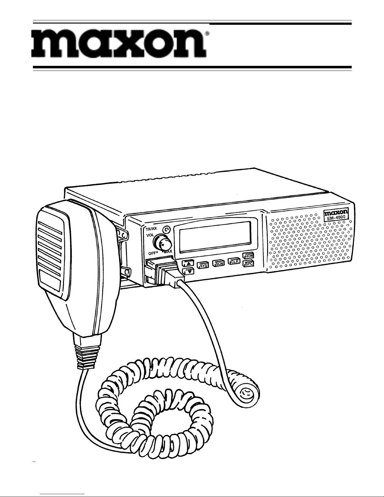
Model EM-4800
800 MHz
EDACS®/GE-MARC
®
Mobile Radio
Operating Instructions
Page 2

NOTICE!
Repairs to this equipment should be made only by an authorized
service technician or at a facility designated by the supplier. Any
repairs, alterations or substitutions of recommended parts made by
the user to this equipment not approved by the manufacturer could
void the user's authority to operate the equipment in addition to
the manufacturers warranty.
NOTICE!
The software contained in this device is copyrighted. Unpublished
rights are reserved under the copyright laws of the United States.
FCC LICENSING
This unit may or may not require a specific FCC license to operate.
The FCC requires that all transmitters in the conventional and some
trunked systems to be licensed by the Federal Communications
Commission. Some trunked operations now are exempt from individual licensing requirements but may be operated in a licensed
system.
Consult your Maxon Dealer regarding specific licensing information (Form 571), or contact the Federal Communications
Commission via phone: 888-CALLFCC (1-888-225-5322) or
through an FCC District office near you.
These operating instructions are published by Maxon America, Inc.,
without any warranty. Improvements and changes necessitated by typographical errors, inaccuracies of current information, or improvements to
programs and/or equipment may be made by Maxon America Inc. at any
time and without notice. Such changes will be incorporated into revisions
or new editions of this manual. No part of this manual may be reproduced
or transmitted in any form or by any means, electronic or mechanical,
(including photocopying and recording) for any purpose without the
sexpress written permission of Maxon America, Inc.
Copyright September 1997 - Maxon America, Inc.
Page 3

TABLE OF CONTENTS
Safety Information 1
Safe Driving Recommendations
for Mobile Radio Users 3
Operating Procedures 4
Introduction 6
Front Panel Controls 7
LCD Indicators 9
Display Messages 10
Alert Tones 10
EDACS Operation
Turning On the Radio 13
Receiving a Call 13
Sending a Call 15
SCAT Operation 16
Conventional Failsoft 17
Scan Operation 17
DTMF Microphone Operation 19
GE-MARC Operation
Turning On the Radio 25
Receiving a Call 25
Sending a Call 26
DTMF Microphone Operation 28
Scan Operation 34
Direct Mode 35
Page 4

TABLE OF CONTENTS, Continued
Conventional Mode Operation
Turning On the Radio 37
Sending a Message 37
Receiving a Message 37
Squelch Adjustment 37
Sending a Manually Entered Interconnect Call
(Using the Optional DTMF Microphone) 38
Scan Operation 39
Maintenance and Basic Care 42
Operator's Radio Setup 44
Warranty Statement 45
EDACS and GE-MARC are registered
trademanes of Ericsson Inc.
Page 5

SAFETY INFORMATION
The operator of any mobile radio should be aware of certain
hazards common to the operation of vehicular radio transmissions. Possible hazards are:
Explosive Atmospheres: Just as it is dangerous to fuel a vehicle
with the motor running, be sure to turn the radio OFF while
fueling the vehicle. Do not carry containers of fuel in the
trunk of the vehicle when the radio is mounted in the trunk.
Interference To Vehicular Electronic Systems: Electronic fuel
injection systems, electronic anti-skid braking systems, electronic cruise control systems, etc. are typical of the types of
electronic devices that may malfunction due to the lack of
protection from radio frequency energy present when transmitting. If the vehicle contains such equipment, consult the
dealer for the make of vehicle and enlist his aid in determining
if such electronic circuits perform normally when the radio is
transmitting.
Dynamite Blasting Caps: Dynamite blasting caps may be
caused to explode by operating a radio within 500 feet of the
caps. Always obey the "Turn Off Two Way Radio" signs
posted where dynamite is being used. When transporting
blasting caps in your vehicle:
a) Carry the blasting caps in a closed metal box with a soft
lining.
b) Leave the radio OFF whenever the blasting caps are
being put into or removed from the vehicle.
Radio Frequency Energy: To prevent burns or related physical
injury from radio frequency energy, do not operate the transmitter when anyone outside of the vehicle is within two feet
of the antenna.
1
Page 6

2
SAFETY INFORMATION, Continued
CAUTION
Before jump starting, charging or changing the vehicle battery, remove the
10A fuse located in the red lead. This will insure that the radio is protected
from damage during the battery charging process. Replace fuse when charging
is completed.
Liquefied Petroleum (LP) Gas Powered Vehicles: Mobile radio
installations in vehicles powered by liquefied petroleum gas
(with the LP gas container in the trunk or other sealed-off
space within the interior of the vehicle) must conform to
the National Fire Protection Association standard (NFPA 58)
which requires that:
a) The space containing the radio equipment shall be
isolated by a seal from the space containing the LP
gas container and its fittings.
b) Outside filling connections shall be used for the LP
gas container.
c) The LP gas container shall be vented to the outside
of the vehicle.
Page 7

SAFE DRIVING RECOMMENDATIONS
FOR MOBILE RADIO USERS*
Exercise caution when using a mobile radio. Become familiar
with information on the safe operation of a mobile radio:
• Keep both hands on the steering wheel and the micro-
phone in its cradle whenever the vehicle is in motion.
• Place calls only when the vehicle is stopped. Use recall
dialing to speed the time it takes to place a call.
• When talking from a moving vehicle is unavoidable,
drive in the slower lane and keep conversations brief.
• If conversation requires taking notes or complex
thought, stop the vehicle in a safe place - then continue
the call.
* As recommended by the AAA (American Automobile Association)
3
Page 8

OPERATING PROCEDURES
Two-way FM radio systems must be operated in accordance
with the Rules and Regulations of the Federal Communications Commission (FCC). Operators of two-way radio equipment must be thoroughly familiar with the rules that apply
to the intended type of radio operation. Following these rules
will help to eliminate confusion, assure the most efficient
use of existing radio channels, and result in a smoothly
functioning radio network. When using this two-way radio,
remember these rules:
1) It is a violation of FCC Rules to interrupt any distress
or emergency message. As the radio operates in much
the same way as a telephone "party line," always listen
to make sure that the line is clear before sending
messages. If someone is sending an emergency
message - such as reporting a fire, or asking for help
in an accident - KEEP OFF THE AIR! Emergency calls
have priority over all other messages.
2) Use of profane or obscene language is prohibited by
federal law.
3) It is against the law to send false call letters, or a false
distress or emergency message.
4) The FCC requires that conversations be kept brief
and confined to business. To save time, use coded
messages whenever possible.
5) Using a radio to send personal messages (except in an
emergency) is a violation of the FCC Rules.
6) It is against Federal Law to repeat or otherwise make
known anything overheard on the radio. Conversations
between others sharing a channel must be regarded as
confidential.
4
Page 9

5
OPERATING PROCEDURES, Continued
7) The FCC requires the operator to identify himself at
certain times by means of call letters. Refer to the rules
that apply to the particular type of operation for the
proper procedure.
NOTE: The GE-MARC and EDACS trunking environments
have automatic identification features built in and do not
require the user to identify by means of call letters.
8) No changes or adjustments shall be made to the equip-
ment except by an authorized or certified electronics
technician.
OPERATING TIPS
Operating the radio in low areas of terrain or while under
power lines or bridges will reduce the effective range of twoway radios. These areas should be avoided whenever possible.
In areas where transmission or reception is poor, insure that
the antenna is vertical (particularly if a glass mount antenna
is used). Moving a few yards in another direction or moving
to higher ground may also help improve radio communication.
Page 10

6
INTRODUCTION
The EM-4800 is a synthesized, microprocessor-based, FM
mobile which provides reliable two-way communications in
the Enhanced Digital Access Communications System (EDACS)
trunking environment, GE-MARC trunking system and conventional communications systems.
In the EDACS or trunked system mode, the user selects a
communications system and group. Channel selection is
transparent to the user and is controlled via digital communication with the system controller. This provides advanced
programmable features and fast access to communication
channels.
In the conventional mode, the user selects a channel and
communicates directly on that channel. A system refers
to a set of channels. A channel is a transmit /receive radio
frequency pair.
The exact operation of the radio will depend on the operating
mode, the radio programming and the particular radio system.
Most features described in this manual may be enabled or
disabled through programming. Consult the system administrator for the particular features that are programmed into the
radio.
This manual provides instructions for operating in either of the
three systems (EDACS, GE-MARC, conventional). A separate
section is provided for each system with a complete set of
instructions for operating the radio within that system.
Page 11
INTRODUCTION, Continued
NOTE: This radio allows the operator to switch between an
EDACS, GE-MARC and conventional system. Special attention
should be given to the system selected and the operating
characteristics of the radio while working within that system.
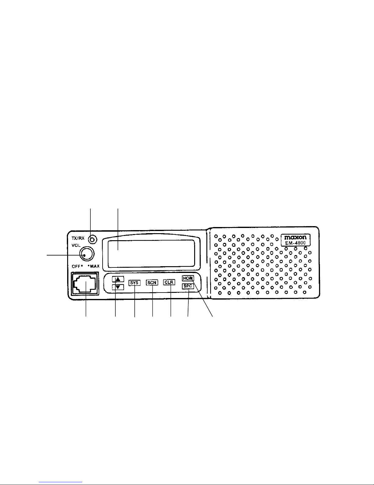
FRONT PANEL CONTROLS
The operating controls are located on the radio's front panel:
a) Power On-Off / Volume control f) CLearR button
b) TX/RX LED g) SCaN button
c) Liquid Crystal Display (LCD) h) SYStem select button
d) HOMe button i) Up /Down control
e) SPeCial call button j) Microphone connector
The radio's LCD provides seven alphanumeric characters to
show the selected system/group, operational mode of the
radio, and radio status indicators. A dual color indicator lamp
glows red when the radio is transmitting (TX) and green when
receiving a signal (RX).
An optional DTMF microphone is available to permit manual
telephone interconnect calls, storing of numbers, etc. Information on DTMF microphone operation is detailed within this
manual.
7
bc
a
g
j
i
h
f
e
d
Page 12

FRONT PANEL CONTROLS, Continued
POWER ON/ OFF-VOLUME KNOB: Provides
power to radio, adjusts receiving volume and
powers off the radio.
GROUP/CHANNEL SELECT BUTTON: Scrolls
through the group or channel lists (depending
upon programming) and provides selection from
scan list, phone list, system, etc.)
SYSTEM SELECT BUTTON: Used with select
buttons above, permits selection of the desired
programmed system.
SCAN ON/OFF BUTTON: Toggles scan operation
on and off; also provides lockout of a selected
group or channel from the scan list when used
with the SYS button.
CLEAR BUTTON: When in the EDACS or
GE-MARC radio system, the CLeaR button
is used to exit the special call mode and return
to the normal system/group display. When in
the conventional radio system, pressing this
button will enable monitoring of the channel.
HOME BUTTON: Automatically selects a desired
group and /or system.
SPECIAL CALL: Places the radio in Special Call
mode, allowing individual and interconnect
calls to be made in an EDACS or GE-MARC
system.
VOL
OFF• •MAX
SYS
CLR
SCN
!
!
HOM
SPC
8
Page 13
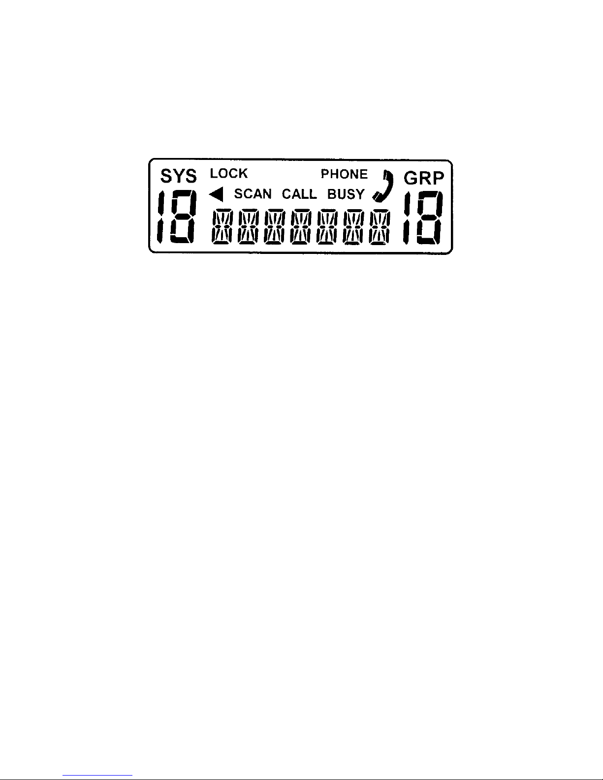
LCD INDICATORS
The 7-character alphanumeric display identifies the selected
system/group, operating modes or error conditions. There
are also status indicators (defined below):
SYS Indicates the number of the current system in
an EDACS, GE-MARC or conventional system.
GRP Indicates the number of the current group in an
EDACS or GE-MARC system.
LOCK This indicator will only be present when the
optional DTMF microphone is used. When
displayed, the keypad is locked on the DTMF
microphone to prevent accidental transmission.
BUSY Indicates when the radio receives a call, when a
conventional channel is in use or when transmitting
on a trunked channel.
PHONE In EDACS or GE-MARC systems, the PHONE and
status flags will appear to indicate the radio is placed in
the special call mode.
CALL Indicates an individual call in EDACS or GE-MARC
systems.
SCAN Indicates scan is enabled.
Indicates a trunked group or conventional channel
is scan enabled.
Indicates the radio is in a special call or interconnect
mode. Also illuminates when PHONE is displayed.
9
"
#
#
Page 14

DISPLAY MESSAGES
During radio operation, various messages are displayed on
the LCD. Typical messages include radio operation (radio
in programming mode) and error messages (radio failure).
MESSAGE DESCRIPTION
NC Out of range - no connection between radio
and system site. Incorrect system selected,
radio is out of coverage area, etc.
AGENCY Indicates an agency call.
ALLCALL Indicates an all call message.
INDV Indicates an individual call.
CONV FS Conventional failsoft - displays when a failure
of the EDACS system occurs. All communica-
tions will be in conventional mode.
PROGRAM Indicates radio is in the programming mode.
SYN LOC Indicates that the synthesizer is unable to load
and lock on the channel properly.
ALERT TONES
The radio generates a number of alert tones (beeps) to indicate
various events or operating conditions. These alert tones can
be enabled or disabled by programming. Function is described
below assuming tones are programmed.
Power-up: A single tone will sound on power-up after the radio
passes a self test.
Carrier Control Timer: If the programmed time for continuous
transmission is exceeded, five short high-pitched warning
tones followed by a single, long low-pitched tone will be
heard. The transmitter will shut down shortly after the alert
10
Page 15

ALERT TONES, Continued
tones are heard, interrupting communications. Release and
re-key the P-T-T button to maintain communications. This will
reset the carrier control timer and turn the transmitter back on.
Key Press: A short low-pitched tone sounds to indicate a
button has been pressed.
TRUNKED OPERATION TONES - Out-Of-Range:
EDACS: A single low-pitched tone will sound immediately
after the P-T-T button is pressed, indicating the radio is out
of range of the repeater. The radio will try to place a call for
a short period (3 seconds) after the initial attempt. The radio
will generate a second low-pitched tone when it gives up
trying to place the call. The system may be off the air or the
radio may require servicing if the radio is within the calling
range and these tones are heard.
GE-MARC: Five beeps will sound shortly after the P-T-T button
is pressed when the radio is out of range of the repeater or the
radio is inoperative. If the "Call Retry" is active, the radio will
try the channel at twenty second intervals for five minutes.
TRUNKED OPERATION TONES - System Busy:
EDACS: Three short, medium-pitched tones will sound when
the P-T-T button is pressed to indicate that the receiving party
is already engaged in another call or the system is busy and
its queue is full. You must re-key later to access the system.
GE-MARC: A low pitched tone will sound when the P-T-T
button is pressed to indicate that all channels are busy.
11
Page 16

ALERT TONES, Continued
TRUNKED OPERATION TONES - Clear To Talk:
A short burst tone indicates that the radio has acquired a
channel and the user may proceed to talk.
TRUNKED OPERATION TONES - Available System:
A short low-pitched tone indicates the radio is attempting
to connect to the first available repeater. A 2-second, highpitched pulsing tone indicates when a repeater is available
and the radio is attempting connection.
TONES IN A CONVENTIONAL SYSTEM - Receive Only Channel:
A warbling tone sounds when a transmit attempt is made on
a receive only channel.
12
Page 17

TURNING ON THE RADIO
Rotate the power on/off-volume control clockwise, out of
detent, to turn on the radio. A short beep (if enabled through
programming) indicates the radio is ready for operation. The
display will show the last selected system and group.
If communication with the system's control channel cannot be
established in the EDACS trunked environment, the NC (out of
range) message will be displayed. You may find it necessary to
move to another location or select another trunking system to
re-establish the control channel link for trunked mode operations.
The radio will automatically transmit a "log-in" message when
turned on or whenever the radio roams into a new system
when changing the group selection. This "log-in" message
includes the logical ID and the group ID for that radio.
RECEIVING A CALL
Turn on the radio as directed above. Adjust the power on/offvolume control clockwise to the desired audio level. Select the
desired system by pressing the SYS button and then using the
!"or # button to scroll to the desired system. Only systems
programmed can be selected.
Select the desired group by pressing the !"or # button. Only
groups programmed can be selected. The radio is now ready
to receive calls.
NOTE: To move quickly through system or group selections,
press and hold the ! or # button.
13
Page 18

EDACS OPERATION
RECEIVING A CALL, Continued
Individual Call
If an individual call (directed only to your radio) is received,
the radio unsquelches on the assigned group. The BUSY icon
will light. If programmed, the individual call receive tones
(one high-pitched followed by one low-pitched tone) will
sound and the originator's ID (dependent upon programming)
is displayed for a short time.
To answer the call, press the P-T-T button and begin talking
if caller's ID is still in display. If caller's ID is no longer in the
display, press the SPC button to display caller's ID, then press
P-T-T and begin talking.
Group Call
When the radio receives a group call, it unsquelches on the
assigned channel and the BUSY icon appears.
If programmed, the group call receive tone (a single tone) will
sound. The group name originator's ID (if programmed) will
be shown in display.
Interconnect Call
When the radio receives an interconnect call (a telephone call
directed to your radio), the radio unsquelches on the assigned
channel and BUSY displays.
If programmed, the interconnect call receive tones (one
high-pitched followed by one low-pitched tone) will sound.
The PHONE and will be displayed. Press the P-T-T button
and begin talking.
14
#
Page 19

15
EDACS OPERATION
SENDING A CALL
Turn the radio on and select the desired system and group.
Ensure that no one is transmitting on the selected system and
group and that the radio is in a service area. If the BUSY icon
is showing on the LCD, place your call later.
Press and hold the P-T-T button. The radio will perform the
necessary signaling required to obtain a communications
channel. If the signaling is unsuccessful, the radio will sound
the appropriate alert tone(s).
When the channel has been acquired, the red TX indicator
lights and the BUSY icon is displayed. If programmed, the
clear to talk tone will sound.
Hold the microphone about 3 inches from your mouth and
speak normally into the microphone. Release the P-T-T button
to listen for a reply.
Sending A Special Call
Press the SPC button to place the radio into the special call
mode and access a pre-programmed alphanumeric list of
individual call or interconnect numbers. If programmed, the
special call alphanumeric list will be displayed. The PHONE
and icon will be displayed.
Use the ! or # button to scroll through the special call list.
Once the desired individual/interconnect call number is
displayed, press and hold the P-T-T button to initiate the call.
The radio performs the necessary signaling required to obtain
a working channel.
#
Page 20

16
EDACS OPERATION
SENDING A CALL, Continued
Sending A Special Call, Continued
Individual Call:
When the signaling is successfully completed,
BUSY is displayed and the clear to talk tone sounds. Speak
directly into the microphone. Release the P-T-T button to listen
for a reply.
Interconnect Call: When the signaling is successfully
completed, BUSY is displayed and the proper DTMF tones will
be sent and heard at the speaker. When someone
answers, press the P-T-T button and speak directly into the
microphone. Release the P-T-T button to listen for a reply.
NOTE: Messages cannot be received when the P-T-T button
is pressed.
If the signaling is unsuccessful, the radio will remain in the
special call mode and sound the appropriate alert tone(s).
To return to the normal system/group, press the CLR button to
exit the special call mode.
SCAT OPERATION
A Single Channel Autonomous Trunking (SCAT) System
operates with the same set of features as a standard EDACS
system. The only significant user change relates to the BUSY
icon. Since only one channel (operating as both control and
working channel) exists in a SCAT system, the BUSY icon
will be displayed when the SCAT channel is in the working
channel mode. When the transmission on the channel is
completed, the BUSY icon will disappear to indicate the
return of SCAT control channel signaling.
Page 21

EDACS OPERATION
CONVENTIONAL FAILSOFT
In the unlikely event of a failure of the EDACS system,
communications may take place in conventional failsoft
mode. The radio will be automatically directed to a communications channel set up for this purpose. During this
mode of operation, CONV FS will be displayed. An increase
in activity on the channel may be noticed, so be careful not
to transmit until the channel is clear (ensure that no BUSY
icon is showing).
Operation during conventional failsoft will be the same as
on a conventional system, except that it will not be possible
to select a communications channel or use emergency and
special call features. When trunking is restored, the radio
will automatically be returned to normal operation.
SCAN OPERATION
Group Scan
Only groups that are part of the radio's scan list may be
scanned. Groups are added to the scan list on a per system
basis through PC programming. Each system's group scan
list is retained in memory when the radio is turned off.
NOTE: The radio may also be programmed to provide priority
group scan capability which operates similar to priority scan
in conventional systems. The following is a description of PC
programmable scan features:
Scan Hang Time: The delay time the radio waits before resum-
ing scan after the P-T-T is released or after the carrier has
dropped a channel.
17
Page 22

EDACS OPERATION
SCAN OPERATION, Continued
Group Scan, Continued
TX Select:
The group the radio will transmit on while scanning.
The radio will be programmed to transmit on either the
scanned group or the selected group.
Scan List (privileges): Pre-programmed list of groups that may be
scanned.
Enable/Disable Scan
To enable group scan, press the SCN button. The SCAN icon
will be displayed. To disable group scan, press and release the
SCN button. The SCAN icon will disappear from the display.
Add/Delete Groups
Groups can be added or deleted from the scan list as needed.
Scan must be disabled to add/delete a group on the scan list.
To add groups: Select the desired group. Press the SYS button,
then press SCN. The icon will appear and the group will
be added to the scan list. If the current group is already in the
scan list, the icon will display. You do not need to repeat
the steps.
To delete groups: Select the desired group. To delete the group
from the scan list, press the SYS button, then press SCN. The
icon will turn off and the group will be removed from the
scan list.
18
"
"
"
Page 23

EDACS OPERATION
SCAN OPERATION, Continued
Priority Group Scan
When scan is enabled, the radio will listen for calls on the
groups in the scan list. While receiving a scanned group call,
the radio will continue to monitor the priority group. If a
call is received on a priority group while the radio is already
connected to a scanned group, that call will be dropped and
the radio will accept the call on the priority group.
DTMF MICROPHONE OPERATION
When an optional DTMF microphone is used with the
EM-4800 mobile radio, several features are available. These
include manually entered individual and interconnect calls,
user storage of individual and interconnect numbers, recall of
user stored individual and interconnect numbers and enable/
disable of keypress alert tones. The following paragraphs
describe these features.
Sending A Manually Entered Individual Call
Press the SPC button to put the radio into the special call
mode. The display will show the last accessed special call
name /number from the pre-programmed special call
selection. PHONE and will be displayed.
Enter the ID number of the radio to be called. The last digit
entered will always be displayed on the far right side. Any
previously entered digits will scroll left. Only the last seven
characters will be visible at a time with the leading character
scrolling off the display upon each new entry.
19
#
Page 24

20
EDACS OPERATION
DTMF MICROPHONE OPERATION, Continued
Sending a Manually Entered Individual Call, Continued
NOTE: To recall the last individual number entered manually
from the keypad, press the 9
RCL
button.
Press and hold the P-T-T button to initiate the call. The radio
performs the necessary signaling required to obtain a working
channel.
When the signaling is successfully completed, the BUSY icon
is displayed and the clear to talk tone sounds. Speak directly
into the microphone. Release the P-T-T to listen for a reply.
If the signaling is unsuccessful, the radio will remain in the
special call mode and sound the appropriate alert tone(s).
When the call is completed, press CLR button once to return
to normal operation. PHONE and will disappear.
Key press: SPC, (Radio ID#), 9
RCL
, P-T-T,
CLR
Sending a Manually Entered Interconnect Call
Press the SPC button to put the radio into the special call
mode. The display will show the last accessed special call
name/number from the pre-programmed special call selection.
PHONE and will be displayed.
Enter the telephone number to be called. The last digit entered
will always be displayed on the far right side. Any previously
entered digits will scroll left. Only the last seven characters
will be visible at a time with the leading character scrolling
off the display upon each new entry.
#
#
MON
Page 25

21
EDACS OPERATION
DTMF MICROPHONE OPERATION, Continued
Sending a Manually Entered Interconnect Call, Continued
NOTE: To recall the last individual number entered manually
from the keypad, press the 9
RCL
key.
Complete the telephone entry by pressing the
PHN
button.
A tone will sound after entry, indicating the digits are for an
interconnect call.
Press and release the P-T-T button to initiate the call. The radio
performs the necessary signaling required to obtain a working
channel.
When the signaling is successfully completed, the BUSY
icon is displayed and the proper DTMF tones will be sent
and heard at the speaker. If the signaling is unsuccessful,
the radio will remain in the special call mode and sound
the appropriate alert tone(s).
When someone answers, press the P-T-T and speak directly
into the microphone. Release the P-T-T to listen for a reply.
When the call is completed, press the
CLR
button once to return
to normal operation. PHONE and will disappear.
Key press: SPC, (Phone #), 9
RCL
,
PHN
, P-T-T,
CLR
Storing Individual and Interconnect Numbers
Press the SPC button to put the radio into the special call
mode. The display will show the last accessed special call
name/number from the pre-programmed special call list.
PHONE and will be displayed.
MON
#
#
MON
*
*
Page 26

22
EDACS OPERATION
DTMF MICROPHONE OPERATION, Continued
Storing Individual and Interconnect Numbers, Continued
Enter the ID or telephone number to be stored. The last
digit entered will always be displayed on the far right. Any
previously entered digits will scroll left. Only the last seven
characters will be visible at a time with the leading character
scrolling off the display upon each new entry.
Complete the entry by pressing the #
IND
button for individual
numbers and the
PHN
button for telephone inter-connect
numbers. A tone will sound after entry to confirm button
press.
Enter a digit between 0 and 9 to select a storage location. A
tone will sound after entry to confirm button press.
There are 10 storage locations for individual numbers and
10 storage locations for interconnect numbers. Press the 8
STR
key to complete the storage procedure. Press the CLR button
once to return to normal operation. PHONE and will
disappear.
Key press (storing an individual call number):
SPC, (Radio ID#), #
IND
, 0 - 9
RCL
, 8
STR
, CLR
Key press (storing an interconnect number):
SPC, (Phone #),
PHN
, 0 - 9
RCL
, 8
STR
, CLR
Recalling Manually Stored Individual and Interconnect Numbers
Press the SPC button to place the radio into the special call
mode. Press the #
IND
button to recall the individual call
list or the
PHN
button to recall the interconnect call list.
The display will blank and a tone will sound. Enter the
*
#
*
*
Page 27

23
EDACS OPERATION
DTMF MICROPHONE OPERATION, Continued
Recalling Manually Stored Individual and Interconnect Numbers
desired storage location number (0-9).
Press the 9
RCL
button. If the number is from the individual call
list, the ID number will be displayed. If the number is from the
interconnect call list, the last seven digits of the telephone will
be displayed. If the memory location is blank, the radio will
sound a low-pitched tone after the 9
RCL
key is pressed.
Once the desired number is displayed, press and release the
P-T-T to initiate the call. The radio performs the necessary
signaling required to obtain a working channel.
To recall and place an individual call:
#
IND
, 0 - 9
RCL
, 9
RCL
, P-T-T
To recall and place an interconnect call
#
IND
, 0 - 9
RCL
, 9
RCL
, P-T-T
Page 28

24
EDACS OPERATION
DTMF MICROPHONE, Continued
Recalling Manually Stored Individual and Interconnect Numbers,
Continued
Individual Call:
When the signaling is successfully completed,
BUSY is displayed, the red TX indicator lights and the clear
to talk tone sounds. Press the P-T-T and speak directly into
the microphone. Release the P-T-T to listen for a reply.
Interconnect Call: When the signaling is successfully com-
pleted, BUSY is displayed and the proper DTMF tone will
be sent and heard in the speaker. When someone answers,
press the P-T-T and speak directly into the microphone.
Release the P-T-T to listen for a reply.
When the call is completed, press the CLR button once to
exit the special call mode and return to normal operation.
Keypad Lock
The keypad on the DTMF microphone can be locked at any
time. To lock the keypad, press the 5
LCK
button. All buttons
on the microphone except P-T-T, and 5
LCK
will be locked,
preventing undesired or accidental key presses. To unlock
the keypad, press the 5
LCK
button.
Keypad Mute
The keypad can be muted at anytime. To mute the keypad,
press and release the 6
MUT
button. All buttons will be muted.
To unmute the keypad, press and release the 6
MUT
button.
~ End of EDACS Operating Section ~
Page 29

25
GE-MARC OPERATION
TURNING ON THE RADIO
Rotate the power on/off-volume control clockwise, out of
detent, to turn on the radio. A short beep (if enabled through
programming) indicates the radio is ready for operation. The
display indicates the last selected system/area and group.
RECEIVING A CALL
Turn on the radio and adjust the audio level. Select the desired
area (system) by pressing the SYS button and then using the
!"and # button to scroll to the desired area. Only areas programmed can be selected.
Select the desired group by pressing the !"and # button to
scroll to the desired group. Only groups programmed can be
selected. The radio is now ready to receive calls.
NOTE: To move quickly through area /system or group selections.
Individual Call: If an individual call (call directed only to
your radio) is received, the radio unsquelches on the assigned
group. The BUSY icon will light. If programmed on, the
individual call received tone (one high-pitched followed by
one low-pitched tone) will sound and the originator's ID or
just "ID" (dependent upon programming) is displayed for
a short time.
To answer the call, press the P-T-T button and begin talking
if caller's ID is still in display. If the caller's ID is no longer
in the display, press the SPC button to display the caller's ID,
then press P-T-T and begin talking.
Page 30

26
GE-MARC OPERATION
RECEIVING A CALL, Continued
Group Call
When the radio receives a group call, it unsquelches on the
assigned channel and the BUSY icon appears. If programmed
on, the group call receive tone (a single tone) will sound. The
group name originator's ID (if programmed) will be shown in
the display.
Interconnect Call
When the radio receives an interconnect call (a telephone call
directed to your radio), the radio unsquelches on the assigned
channel and the BUSY icon appears. If programmed on, the
interconnect call received tones (one high-pitched tone
followed by one low-pitched tone) will sound. The PHONE
and icon will be displayed. Press the P-T-T button and
begin talking.
SENDING A CALL
Turn the radio on and select the desired area (system) and
group. Ensure that no one is transmitting on the selected area
and group and that the radio is in a service area.
Press and release the P-T-T button. The radio will perform
the necessary signaling required to obtain a communications
channel. If the signaling is unsuccessful, the radio will sound
the appropriate alert tone(s).
A one second low-frequency tone will sound if the call cannot
be completed due to all available channels being busy, and
the BUSY icon will show on the LCD. Retry the call later.
#
Page 31

27
GE-MARC OPERATION
SENDING A CALL, Continued
A sequence of five beeps will sound if the radio cannot access a
channel due to being out of range of the GE-MARC system or
an inoperative radio. Any subsequent call requests will be
ignored for 20 seconds. However, if the area is changed, a call
request may be initiated in the new area.
NOTE: If the call retry option has been programmed and is
active, the radio will automatically try to acquire a channel
at 20 second intervals for five minutes before returning to the
normal area and group display.
When the channel has been acquired, the red TX indicator
lights and the BUSY icon will appear. If programmed, the
clear to talk tone will sound.
Hold the microphone about 3 inches from your mouth and
speak normally into the microphone. Release the P-T-T button
to listen for a reply.
Sending A Special Call
Press the SPC button to place the radio into the special call
mode and access a pre-programmed alphanumeric list of
individual call or interconnect numbers. If programmed, the
special call alphanumeric list will be displayed. The PHONE
and icon will be displayed.
Use the ! or # button to scroll through the special call list.
Once the desired individual / interconnect call number is
displayed, press and hold the P-T-T button to initiate the call.
The radio performs the necessary signaling required to obtain
a working channel.
#
Page 32

28
GE-MARC OPERATION
SENDING A SPECIAL CALL, Continued
Individual Call:
When the signaling is successfully completed,
the BUSY icon appears and the clear to talk tone sounds. Hold
the microphone about 3 inches from your mouth and speak
normally into the microphone. Release the P-T-T button to
listen for a reply.
Interconnect Call: When the signaling is successfully com-
pleted, the BUSY icon appears and the proper DTMF tones
will be sent and heard at the speaker.
When someone answers, press the P-T-T button and speak
directly into the microphone. Release the P-T-T button to listen
for a reply. Messages cannot be received when the
P-T-T button is pressed.
If the signaling is unsuccessful, the radio will remain in the
special call mode and sound the appropriate alert tone(s). To
exit the special call mode and return the normal area/group,
press the CLR button.
DTMF MICROPHONE OPERATION
When an optional DTMF microphone is used with the mobile
radio, several features are available. These include manually
entered individual and interconnect calls, storage of individual
and interconnect calls, user storage of individual and interconnect numbers, recall of user stored individual and interconnect
numbers and enable /disable of keypress alert tone.
The following paragraphs describe these features.
Page 33

29
GE-MARC OPERATION
DTMF MICROPHONE OPERATION, Continued
Sending A Manually Entered Individual Call
Press the SPC button to put the radio into the special call
mode or button 7 to put the radio into conference call mode.
The SYS icon displays "SP" and the GRP icon displays last
accessed call number from the pre-programmed special call
list for this area. PHONE and icon will appear.
Enter the ID number of the radio to be called. The last
digit entered will always be displayed in the far right. Any
previously entered digits will scroll left. Only the last seven
characters will be visible at a time with the leading character
scrolling off the display upon each new entry.
NOTE: To recall the last manually entered number, press the
9
RCL
key.
Complete the entry by pressing #
IND
. This indicates the digits
are for an individual call. A tone will sound to confirm key
press.
Press and release the P-T-T button to initiate the call. The radio
performs the necessary signaling required to obtain a working
channel. When the signaling is successfully completed, the
BUSY icon will display and the clear to talk tone sounds.
Hold the microphone about 3 inches from your mouth and
speak directly into the microphone. Release the P-T-T to
listen for a reply. If the signaling is unsuccessful, the radio
will remain in the special call mode and sound the appropriate
alert tone(s).
When the call is completed, press the
CLR
key once to
#
MON
Page 34

GE-MARC OPERATION
DTMF MICROPHONE OPERATION, Continued
Sending A Manually Entered Individual Call, Continued
return to normal operation. PHONE and icon will
disappear.
Key press: SPC, 0 - 9
RCL
, #
IND
, P-T-T,
CLR
Key press (conf. call): SPC, 0 - 9
RCL
, #
IND
, P-T-T,
CLR
Sending A Manually Entered Interconnect Call
Press the SPC button to put the radio into the special call mode
or button 7 to put the radio into conference call mode. The SYS
icon displays "SP" and the GRP icon displays last accessed
call number from the pre-programmed special call list or it
will be blank if no special call list is programmed for this area.
PHONE and icon will appear.
Enter the telephone number to be called. The last digit entered
will always be displayed in the far right side. Any previously
entered digits will scroll left. Only the last seven characters
will be visible at a time with the leading character scrolling
off the display upon each new entry.
NOTE: To recall the last manually entered number from the
keypad, press 9
RCL
key.
Complete the telephone entry by pressing the
PHN
button.
The
PHN
button indicates the digits are for an interconnect
call. A tone will sound to confirm key press.
Press and release the P-T-T button to initiate the call. The radio
performs the necessary signaling required to obtain a working
channel.
30
#
*
#
MON
MON
*
Page 35

31
GE-MARC OPERATION
DTMF MICROPHONE OPERATION, Continued
Sending A Manually Entered Interconnect Call, Continued
When the signaling is successfully completed, the BUSY icon
will appear and the proper DTMF tones will be sent and heard
at the speaker. If the signaling is unsuccessful, the radio will
remain in the special call mode and sound the appropriate
alert tone(s).
When someone answers, press the P-T-T and speak directly
into the microphone. Release the P-T-T to listen for a reply.
When the call is completed, press the
CLR
button to return to
normal operation. PHONE and icon will disappear.
Key press: SPC, 0 - 9
RCL
,
PHN
, P-T-T,
CLR
Key press (conf. call): 7, 0 - 9
RCL
,
PHN
, P-T-T,
CLR
Storing Individual and Interconnect Numbers
To store an individual call number:
SPC, 0 - 9
RCL
, #
IND
, 0 - 9
RCL
, 8
STR
To store an individual conference number:
7, 0 - 9
RCL
, #
IND
, 0 - 9
RCL
, 8
STR
To store an interconnect number:
SPC, 0 - 9
RCL
,
PHN
, 0 - 9
RCL
, 8
STR
To store an interconnect conference number:
7, 0 - 9
RCL
,
PHN
, 0 - 9
RCL
, 8
STR
#
*
*
*
*
MON
MON
MON
Page 36

32
GE-MARC OPERATION
DTMF MICROPHONE OPERATION, Continued
Storing Individual and Interconnect Numbers, Continued
Press the SPC button to put the radio into the special call mode
or button 7 to put the radio into conference call mode. The SYS
icon displays "SP" and the GRP icon displays last accessed
call number from the pre-programmed special call list or it
will be blank if no special call list is programmed for this area.
PHONE and icon will appear.
Enter the ID or telephone number to be stored. The last digit
entered will always be displayed in the far right side of the
display. Any previously entered digits will scroll left. Only
the last seven characters will be visible at a time with the
leading character scrolling off the display upon each new
entry.
Complete the entry by pressing the #
IND
key for individual
numbers and the
PHN
key for telephone interconnect num-
bers. A tone will sound upon entry.
Enter a digit between 0 and 9 to select a storage location. A
tone will sound to confirm key press. There are 10 storage
locations for individual numbers and 10 storage locations
for interconnect numbers.
Press the 8
STR
key to complete the storage procedure. Press the
CLR
key once to return to normal operation. The PHONE and
icon will disappear.
Key press (storing individual call numbers):
SPC, 0 - 9
RCL
, (Radio ID#), 0 - 9
RCL
, 8
STR , CLR
Key press (storing individual conference numbers):
7, 0 - 9
RCL
, (Radio ID#), 0 - 9
RCL
, 8
STR , CLR
#
*
#
MON
MON
MON
Page 37

33
GE-MARC OPERATION
DTMF MICROPHONE OPERATION, Continued
Storing Individual And Interconnect Numbers, Continued
Key press (storing an interconnect number):
SPC, 0 - 9
RCL
,
PHN
, 0 - 9
RCL
, 8
STR
Key press (storing an interconnect conference number:
7, 0 - 9
RCL
,
PHN
, 0 - 9
RCL
, 8
STR
Recalling Manually Stored Individual and Interconnect Numbers
Key press (recall/place individual call):
SPC, #
IND
, 0 - 9
RCL
, 9
RCL
, P-T-T
Key press (recall/place ind. call in conference call mode):
7, #
IND
, 0 - 9
RCL
, 9
RCL
, P-T-T
Key press (recall/place interconnect call):
SPC,
PHN
, 0 - 9
RCL
, 9
RCL
, P-T-T
Key press (recall/place intercon. call - conference call mode):
7,
PHN
, 0 - 9
RCL
, 9
RCL
, P-T-T
Press the SPC button to place the radio into the special call
mode. Press the #
IND
button to recall the individual call list or
the
PHN
button to recall the interconnect call list. The display
will blank and a tone will sound.
Enter the desired storage location number 0-9. Press the 9
RCL
key. If the number is from the individual call list, the ID number will be displayed. If the number is from the interconnect
call list, the last seven digits of the telephone number will be
displayed.
If the memory location is blank, the radio will sound a
low pitched tone after the 9
RCL
button is pressed. Once the
desired number is displayed, press and release the P-T-T to
*
*
*
*
*
Page 38

34
GE-MARC OPERATION, Continued
Recalling Manually Stored Individual and Interconnect Numbers,
Continued
initiate the call. The radio performs the necessary signaling
required to obtain a working channel.
Individual Call: When the signaling is successfully completed,
BUSY is displayed, the red TX indicator lights and the clear to
talk tone sounds. Press the P-T-T and speak directly into the
microphone. Release the P-T-T to listen for a reply.
Interconnect Call: When the signaling is successfully com-
pleted, BUSY is displayed and the proper DTMF tone will
be sent and heard in the speaker. When someone answers,
press the P-T-T and speak directly into the microphone.
Release the P-T-T to listen for a reply.
When the call is completed, press the SPC button
twice
to
exit the special call mode and return to normal operation.
SCAN OPERATION
Wide Area System Scan
When operating within a GE-MARC System, the radio may be
programmed to scan up to 20 groups from other GE-MARC
systems. The radio will scan the groups in the selected systems
and if its programmed collect tone is not seen, then it will
proceed to scan and the groups of the systems in the wide
area scan list. The group selection may change upon switching
to the new system.
Group Scan
Only Groups that are part of the radio's scan list may be
Page 39

35
GE-MARC OPERATION
SCAN OPERATION, Continued
Group Scan, Continued
scanned. Groups are added to the scan list on a per-system
basis through PC programming. Each system's group scan
list is retained in memory when the radio is turned off.
Enable/Disable Group Scan
To enable group scan, press the SCN button. The SCAN icon
will appear. To disable group scan, press and release the SCN
button - the SCAN icon will disappear.
Add/Delete Groups
Groups can be added or deleted from the scan list as desired.
NOTE: Scan must be disabled to add or delete a Group on
the scan list.
To add groups: Select the desired group to be added. Press the
SYS button, then press SCN. The icon will appear and the
group will be added to the scan list. If the current group is
already included in the scan list, the icon will display.
To delete groups: Select the desired group to be deleted. Press
the SYS button and then press the SCN button. The icon
will turn off and the group will be removed from the scan list.
DIRECT MODE
The direct (or talk around) mode provides short range, lineof-sight communications - this mode is not functional in a
trunked system.
"
"
"
Page 40

36
GE-MARC OPERATION
DIRECT MODE, Continued
Receiving and Sending A Message
Press the SYS button and use the !"or # button to select the
direct mode system. The SYS display will indicate the current
system selected.
Press CLR to disable squelch and monitor the channel. Adjust
the volume control to the desired audio level.
Press the P-T-T and send the message. The red TX indicator
will illuminate and the BUSY icon will appear. Release the
P-T-T to listen for a reply.
~ End of GE-MARC Operating Section ~
Page 41

37
CONVENTIONAL MODE OPERATION
TURNING ON THE RADIO
Rotate the power on-off/volume control clockwise, out of
detent, to turn on the radio. A short beep (if enabled through
programming) indicates the radio is ready for operation. The
display will indicate the last selected system and channel.
SENDING A MESSAGE
Turn on the radio and adjust the power on-off / volume
control to the desired audio level. Select a system by
pressing the SYS button and then using the ! and #
button to scroll to the desired system. Only programmed
systems can be selected. Select the desired channel by
pressing the ! or # button to scroll through the channel
selections. Only programmed channels can be selected.
Press the CLR button to disable squelch and monitor the
channel. Re-adjust the volume control if necessary.
Hold the microphone about 3 inches from your mouth, press
the P-T-T and speak normally into the microphone.
Release the P-T-T when your transmission is complete and
listen for a reply.
RECEIVING A MESSAGE
With the radio powered on, make system and group selections
as detailed above. Re-adjust the volume control if necessary.
The radio is now ready to receive calls.
SQUELCH ADJUSTMENT
In normal operation the squelch is automatically set by the
Page 42

38
CONVENTIONAL MODE OPERATION
SQUELCH ADJUSTMENT, Continued
radio and does not require adjusting. If it becomes necessary
to adjust the squelch, use the following procedure.
NOTE: The radio must be on a conventional system or an
EDACS working channel (i.e., receiving a voice call) to adjust
the squelch. It is recommended to adjust squelch from a
conventional system.
Press and hold the SYS button. Use the ! button to open
the squelch or the # button to close the squelch.
SENDING A MANUALLY ENTERED INTERCONNECT CALL
(USING THE OPTIONAL DTMF MICROPHONE)
Select a channel in the conventional system that has telephone
interconnect capability. The radio should be programmed for
DTMF operation on this channel.
Press and hold the P-T-T to key the transmitter. While holding
the P-T-T, press either the
PHN
or #
IND
button (as required by
the radio system) to obtain a telephone line. The radio will
transmit the selected tone.
Release the P-T-T and listen for a dial tone. When the dial tone
is heard, press and hold the P-T-T while you enter the desired
telephone number through the microphone key pad. As you
enter each digit, a sidetone will be heard in the speaker as the
radio transmits the DTMF tone (if programmed).
After all digits have been keyed, release the P-T-T. When
someone answers, press the P-T-T and speak directly into the
microphone. Release the P-T-T when you stop talking to listen
for a reply.
*
Page 43

39
CONVENTIONAL MODE OPERATION
SENDING A MANUALLY ENTERED INTERCONNECT CALL,
Continued
At the completion of the call, press and hold the P-T-T and
then press the
PHN
or #
IND
key (as required by the radio system)
to disconnect from the interconnect facility.
SCAN OPERATION
Only channels that are part of the radio's scan list may be
scanned. Channels are added to the scan list on a per system
basis through PC programming. The scan list is retained in
memory when the radio is turned off. The following is a
description of PC programmable scan features:
Scan Hang Time: The delay of time the radio waits before
resuming scan after P-T-T is released or after the carrier
has dropped a channel.
TX Select: The channel the radio will transmit on while
scanning. The radio will be programmed to transmit on
either the scanned channel or the selected channel.
Scan List (privileges): Pre-programmed list of channels that
may be scanned.
Enable / Disable Scan
To enable scan, press the SCN button. The SCAN icon will
display. To disable scan, press and release the SCN button.
The SCAN icon will disappear from the display.
Add /Delete Channels
Channels can be added or deleted from the scan list as
needed. NOTE: Scan must be disabled to add/delete a
*
Page 44

40
CONVENTIONAL MODE OPERATION
SCAN OPERATION, continued
Add/Delete Channels, continued
channel on the scan list.
To add channels: Select the desired channel. Press the SYS
button, then press SCN. The icon will appear and the
channel will be added to the scan list. If the current channel
is already in the scan list, the icon will display. You do not
need to repeat the steps.
To delete channels: Select the desired channel. To delete the
channel from the scan list, press the SYS button, then press
SCN. The icon will turn off and the group will be removed
from the scan list.
The Selected Channel
The selected channel is the channel in the display when scan
is activated . When a signal is not being received, the radio
reverts to this channel for transmitting. When a signal is being
received, the radio can be PC programmed to either revert to
the selected channel or remain on the received channel for
transmission.
The selected channel does not necessarily have to be a
channel in the scan list. It will be temporarily entered into
the scan list and scanned until the selected channel is
changed.
When scan is turned off, the radio will return to the selected
channel.
"
"
"
Page 45

41
CONVENTIONAL MODE OPERATION
SCAN OPERATION, Continued
Display
Channel Indicator:
While no signal is being received, the
channel indicator will always show the selected channel.
When an active channel is received, the channel indicator
will show the received channel.
Scan Indicator: When the SCN button is pushed, the radio
will light the SCAN icon and begin scanning. The SCAN
indicator will flash when the microphone is taken off-hook
to show the radio is no longer scanning (only if the radio
is programmed not to scan off-hook).
Transmitting While In Scan
Transmitter operation in scan is determined by the programming of the radio's personality:
Off hook - scan not enabled (default): With off-hook scan
disabled (normal default condition), all scanning will stop
when the microphone is taken off-hook. The SCAN icon
will flash to show all scanning has stopped. If a signal is
not being received when the microphone is placed off-hook,
the radio will transmit on the selected channel. If a signal
is being received when the microphone is taken off-hook,
the radio can be PC programmed (using the "scan transmit
option") to either stay on the receive channel or revert to
the selected channel. When the microphone is placed back
on-hook, the radio will immediately start scanning, even if
the received channel was still active.
Page 46

42
CONVENTIONAL MODE OPERATION
SCAN OPERATION, Continued
Transmitting While In Scan, Continued
Off-hook scan enabled:
With off-hook scan enabled, moving
the microphone off-hook will not affect scan operation. The
radio will continue scanning. If a signal is not being received,
the radio will transmit on the selected channel. If a signal is
being received, the radio can be PC programmed (using the
"scan transmit channel" option) to either stay on the receive
channel or revert to the selected channel when the microphone P-T-T is keyed.
On-hook: When the microphone is on-hook and the radio
is not receiving a channel, the radio always transmits on
the selected channel.
When the radio is receiving a channel, the radio's personality
can be programmed to transmit either on the received channel
or the selected channel. If the radio was programmed for
the selected channel, the display will change to the selected
channel when the transmitter is keyed.
MAINTENANCE AND BASIC CARE
ANTENNA REMOVAL: It is strongly recommended that your
antenna be removed from its mounting prior to passing
through an automatic car wash in order to prevent antenna
and /or vehicle damage. Refer to your antenna instruction
guide for information on how to safely remove the antenna
from its mounting.
FUSE REPLACEMENT: The radio is protected by one or more
fuses located in the cables connected to the vehicle power
Page 47

43
CONVENTIONAL MODE OPERATION
MAINTENANCE AND BASIC CARE, Continued
source(s). If the radio fails to operate, the problem may be
a defective fuse. Replace the fuse(s) with a similar type and
size. The fuse may be obtained from the radio supplier or
most electrical supply stores. If, however, the trouble persists
(the radio continues to blow fuses or remains inoperative)
check with the radio supplier.
Radio power (red lead) 10 Amp fast blow fuse
Type AGC15
JUMP STARTING THE VEHICLE: Before jump starting, charging
or changing the vehicle battery, remove the 10A fuse located
in the red lead. This will insure that the radio is protected
from damage during the battery charging process. Replace
fuse when charging is completed.
Page 48

44
OPERATOR'S RADIO SETUP
Radio Type:
Frequency Band:
Operator's Name:
SYSTEM SYSTEM TRUNKED (T) GRP/CHAN GRP/CHAN
NUMBER NAME or CONV (C) NUMBER NAME
Page 49

LIMITED WARRANTY
Maxon America, Inc. (herein "Maxon") warrants each new radio product manufactured or
supplied by it to be free from defects in material or workmanship under normal use and
service for two (2) years, provided that the user has complied with the requirements stated
herein. The warranty period begins on the date of purchase from an Authorized Maxon Sales
and Service Outlet. This warranty is not assignable or transferrable. Maxon is not responsible
for any ancillary equipment which is attached or used in conjunction with Maxon products.
During this period, if the end user experiences difficulties with a Maxon product, it should
be returned to the Authorized Maxon Sales and Service Outlet from which it was purchased.
The Authorized Maxon Sales and Service Outlet will return for repair to Maxon America, Inc.
or to its Authorized Repair Depot. Product returned to Maxon America, Inc. must be shipped
freight prepaid and be accompanied by a Return Authorization (RA) number, obtained prior to
shipment from Maxon's Customer Service Department. The user is responsible for the payment
of any charges or expenses incurred for the removal of the product from the vehicle or other
site of its use, for the reinstallation of the repaired unit in such site, for the transportation of the
product to the place of repair and for the return of the repaired product to the place of its use.
Maxon shall have no obligation to make repairs or to cause replacement required with result
from normal wear and tear or necessitated in whole or in part by catastrophe, the fault or
negligence of the user, improper or unauthorized alterations, repairs to the product, incorrect
wiring, use of the product in a manner for which it was not designed, or by causes external to
the product. This warranty is void if the serial number to altered, defaced or removed.
Maxon's sole obligation hereunder shall be to repair or replace the product covered in this
Warranty. Replacement, at Maxon's option may include a similar or higher-featured product.
Repair, at Maxon's option, may include the replacement of parts or boards with functionally
equivalent reconditioned or new parts or boards. Replaced parts, accessories, batteries or
boards are warranted for the balance of the original time period. All replaced parts,
accessories, batteries or boards become the property of Maxon America, Inc.
THE EXPRESS WARRANTIES CONTAINED HEREIN ARE IN LIEU OF ALL OTHER
WARRANTIES, EITHER EXPRESSED OR IMPLIED OR STATUTORY, INCLUDING,
WITHOUT LIMITATION, ANY WARRANTY OF MERCHANTABILITY OR FITNESS
FOR A PARTICULAR PURPOSE.
FOR ANY PRODUCT WHICH DOES NOT COMPLY WITH THE WARRANTY SPECIFIED,
THE SOLE REMEDY WILL BE REPAIR OR REPLACEMENT. IN NO EVENT WILL MAXON
AMERICA, INC. BE LIABLE TO THE BUYER OR ITS CUSTOMERS FOR ANY DAMAGES,
INCLUDING ANY SPECIAL, INCIDENTAL, INDIRECT OR CONSEQUENTIAL DAMAGES,
OR THE LOSS OF PROFIT, REVENUE OR DATA ARISING OUT OF THE USE OF OR THE
INABILITY TO USE THE PRODUCT.
This Warranty is void for sales and deliveries outside of the U.S.A.
45
Page 50

Maxon America, Inc.
Business Radio Division
10828 NW Air World Drive
Kansas City, Missouri 64153
Telephone: 816/891-6320
Fax: 816/891-8815
U.S. P/N: 680-090-2008
Printed in Korea
 Loading...