

Page 1
M-16-40
AUGUST 2018
© MAXON Lift Corp. 2018
Page 2

Page 3
11921 Slauson Ave.
Santa Fe Springs, CA. 90670
LIFT CORP.
CUSTOMER SERVICE:
TELEPHONE (562) 464-0099 TOLL FREE (800) 227-4116
FAX: (888) 771-7713
NOTE: For latest version of all Manuals (and replacements), download the
Manuals from Maxon’s website at www.maxonlift.com.
WARRANTY/ RMA POLICY & PROCEDURE
LIFTGATE WARRANTY
Type of Warranty: Full Parts and Labor
Term of Warranty: Standard Liftgates - 2 years from ship date or 6,000 cycles
Premium Liftgates - 2 years from ship date or 10,000 cycles
This warranty shall not apply unless the product is installed, operated and maintained in accordance with MAXON Lift’s specifi cations as set forth in
MAXON Lift’s Installation, Operation and Maintenance manuals. This warranty does not cover normal wear, maintenance or adjustments, damage or
malfunction caused by improper handling, installation, abuse, misuse, negligence, or carelessness of operation. In addition, this warranty does not
cover equipment that has had unauthorized modifi cations or alterations made to the product.
MAXON agrees to replace any components which are found to be defective during the fi rst 2 years of service, and will reimburse for labor based on
MAXON’s Liftgate Warranty Flat Rate Schedule. (Copy of the Flat Rate is available at www.maxonlift.com.)
All warranty repairs must be performed by an authorized MAXON warranty facility. For any repairs that may exceed $500, including parts and labor,
MAXON’s Technical Service Department must be notifi ed and an “Authorization Number” obtained.
All claims for warranty must be received within 30 Days of the repair date, and include the following information:
1. Liftgate Model Number and Serial Number
2. The End User must be referenced on the claim
3. Detailed Description of Problem
4. Corrective Action Taken, and Date of Repair
5. Parts used for Repair, Including MAXON Part Number(s)
6. MAXON R.M.A. # and/or Authorization # if applicable (see below)
7. Person contacted at MAXON if applicable
8. Claim must show detailed information i.e. Labor rate and hours of work performed
Warranty claims can also be placed online at www.maxonlift.com. Online claims will be given priority processing.
All claims for warranty will be denied if paperwork has not been received or claim submitted via Maxon website for processing by MAXON’s Warranty
Department within 30 days of repair date.
All components may be subject to return for inspection, prior to the claim being processed. MAXON products may not be returned without prior written
approval from MAXON’s Technical Service Department. Returns must be accompanied by a copy of the original invoice or reference with original
invoice number and are subject to a credit deduction to cover handling charges and any necessary reconditioning costs. Unauthorized returns will be
refused and will become the responsibility of the returnee.
Any goods being returned to MAXON Lift must be pre-approved for return, and have the R.M.A. number written on the outside of the package in plain
view, and returned freight prepaid. All returns are subject to a 15% handling charge if not accompanied by a detailed packing list. Returned parts
are subject to no credit and returned back to the customer. Defective parts requested for return must be returned within 30 days of the claim date for
consideration to:
10321 Greenleaf Ave., Santa Fe Springs, CA 90670
MAXON’s warranty policy does not include the reimbursement for travel time, towing, vehicle rental, service calls, oil, batteries or loss of income due to
downtime. Fabrication or use of non Maxon parts, which are available from MAXON, are also not covered.
MAXON’s Flat Rate Labor Schedule takes into consideration the time required for diagnosis of a problem.
All Liftgates returned are subject to inspection and a 15% restocking fee. Any returned Liftgates or components that have been installed or not returned
in new condition will be subject to an additional reworking charge, which will be based upon the labor and material cost required to return the Liftgate or
component to new condition.
PURCHASE PART WARRANTY
Term of Warranty: 1 Year from Date of Purchase.
Type of Warranty: Part replacement only. MAXON will guarantee all returned genuine MAXON replacement parts upon receipt and inspection of parts
and original invoice.
All warranty replacements parts will be sent out via ground freight. If a rush shipment is requested, all freight charges will be billed to the requesting
party.
MAXON Lift Corp.
Attn: RMA#__
Page 4

TABLE OF CONTENTS
WARNINGS ........................................................................................................................... 6
SAFETY INSTRUCTIONS .................................................................................................... 7
LIFTGATE TERMINOLOGY .................................................................................................. 8
PERIODIC MAINTENANCE .................................................................................................. 9
PERIODIC MAINTENANCE CHECKS .................................................................................. 9
PREVENTATIVE MAINTENANCE (PM) CHECKLIST ......................................................... 10
CHECKING HYDRAULIC FLUID .........................................................................................11
CHANGING HYDRAULIC FLUID ........................................................................................ 13
PRESSURIZING HYDRAULIC SYSTEM ............................................................................ 15
TORSION BAR REPLACEMENT & ADJUSTMENT............................................................ 16
DECALS .............................................................................................................................. 26
SYSTEM DIAGRAMS ......................................................................................................... 28
PUMP MOTOR & VALVE OPERATION (MANUAL CLOSE) ............................................... 28
PUMP MOTOR & VALVE OPERATION (EQUIPPED WITH HYDRAULIC CLOSER) ......... 29
HYDRAULIC SCHEMATIC (MANUAL CLOSE) .................................................................. 30
HYDRAULIC SCHEMATIC (EQUIPPED WITH HYDRAULIC CLOSER) ............................ 31
ELECTRICAL SCHEMATIC (MANUAL CLOSE) ................................................................ 32
ELECTRICAL SCHEMATIC (EQUIPPED WITH HYDRAULIC CLOSER) ........................... 33
ELECTRICAL SCHEMATIC - JUMPER HARNESS ASSEMBLY ........................................ 34
ELECTRICAL SCHEMATIC - HOUSING COVER ASSEMBLY (WITHOUT LIGHTS) ......... 35
ELECTRICAL SCHEMATIC - HOUSING COVER ASSEMBLY (WITH FOUR LIGHTS) .... 36
ELECTRICAL SCHEMATIC - HOUSING COVER ASSEMBLY, FOREIGN VEHICLE
(WITH 6 LIGHTS ) ...............................................................................................................37
DMD ELECTRICAL VALUES .............................................................................................. 38
RECOMMENDED BOLT TORQUES .................................................................................. 39
Page 5

THIS PAGE INTENTIONALLY LEFT BLANK
Page 6

Comply with the following WARNINGS and SAFETY INSTRUCTIONS while maintaining
Liftgates. See Operation Manual for operating safety requirements.
!
WARNINGS
• Do not stand, or allow obstructions, under the platform when lowering the Liftgate. Be sure your
feet are clear of the Liftgate.
• Keep fi ngers, hands, arms, legs, and feet clear of moving Liftgate parts (and platform
edges) when operating the Liftgate.
• Correctly stow platform when not in use. Extended platforms could create a hazard for
11921 Slauson Ave. Santa Fe Springs, CA. 90670 (800) 227-4116 FAX (888) 771-7713
people and vehicles passing by.
• Disconnect Liftgate power cable from battery before repairing or servicing Liftgate.
• If it is necessary to stand on the platform while maintaining the Liftgate, keep your feet and any
objects clear of the inboard edge of the platform. Your feet or objects on the platform can become
trapped between the platform and the Liftgate housing cover.
• Recommended practices for welding on steel parts are contained in the current AWS (American
Welding Society) D1.1 Structural Welding Code - Steel. Damage to Liftgate and/or vehicle, and
personal injury could result from welds that are done incorrectly.
• Recommended practices for welding on aluminum parts are contained in the current AWS
(American Welding Society) D1.2 Structural Welding Code - Aluminum. Damage to Liftgate
and/or vehicle, and personal injury could result from welds that are done incorrectly.
WARNING
6
Page 7

SAFETY INSTRUCTIONS
• Read and understand the instructions in this Maintenance Manual before performing mainte-
nance on the Liftgate.
• Before operating the Liftgate, read and understand the operating instructions in Operation
Manual.
• Comply with all WARNING and instruction decals attached to the Liftgate.
• Keep decals clean and legible. If decals are illegible or missing, replace them. Free replacement
decals are available from Maxon Customer Service.
• Consider the safety and location of bystanders and location of nearby objects when operating the
Liftgate. Stand to one side of the platform while operating the Liftgate.
• Do not allow untrained persons to operate the Liftgate.
• Wear appropriate safety equipment such as protective eyeglasses, faceshield and clothing while
performing maintenance on the Liftgate and handling the battery. Debris from drilling and contact
with battery acid may injure unprotected eyes and skin.
• Be careful working by an automotive type battery. Make sure the work area is well ventilated and
there are no fl ames or sparks near the battery. Never lay objects on the battery that can short the
terminals together. If battery acid gets in your eyes, immediately seek fi rst aid. If acid gets on your
skin, immediately wash it off with soap and water.
SAFETY INSTRUCTIONS
• If an emergency situation arises (vehicle or Liftgate) while operating the Liftgate, release the con-
trol switch to stop the Liftgate.
• A correctly installed Liftgate operates smoothly and reasonably quiet. The only noticeable noise
during operation comes from the power unit while the platform is raised. Listen for scraping, grating and binding noises and correct the problem before continuing to operate Liftgate.
• Use only Maxon Authorized Parts for replacement parts. Provide Liftgate model and serial number information with your parts order. Order replacement parts from:
MAXON LIFT CORP. Customer Service
11921 Slauson Ave., Santa Fe Springs, CA 90670
Online: www.maxonlift.com
Express Parts Ordering: Phone (800) 227-4116 ext. 4345
Email: Ask your Customer Service representative
11921 Slauson Ave. Santa Fe Springs, CA. 90670 (800) 227-4116 FAX (888) 771-7713
7
Page 8
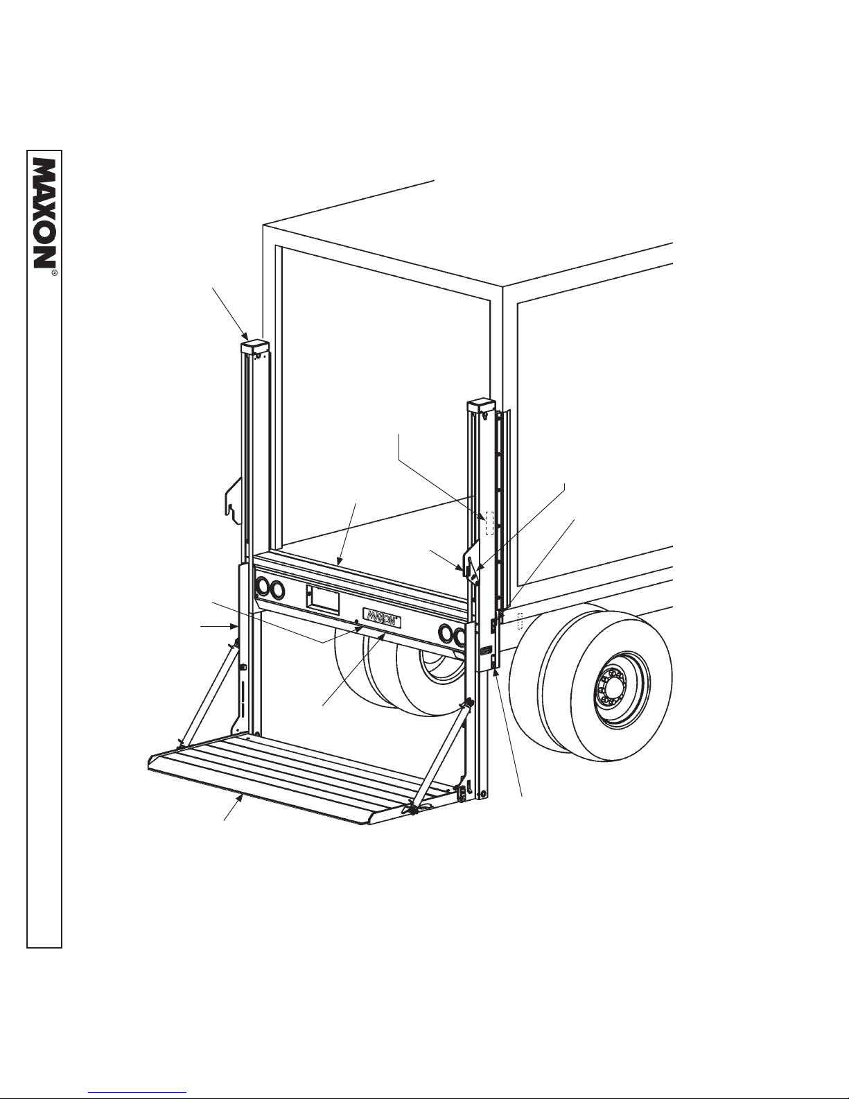
LIFTGATE TERMINOLOGY
11921 Slauson Ave. Santa Fe Springs, CA. 90670 (800) 227-4116 FAX (888) 771-7713
(BEHIND COVER)
COLUMN
POWER UNIT
RUNNER
UP/DOWN
CONTROL SWITCH
(INBOARD)
MAIN FRAME
TRANSIT
HOOK
PLATFORM
LATCH
UP/DOWN
CONTROL SWITCH
(OUTBOARD)
HOUSING
COVER
PLATFORM
FOLD/UNFOLD SWITCH
(IF EQUIPPED WITH
HYDRAULIC CLOSER)
8
Page 9
PERIODIC MAINTENANCE
PERIODIC MAINTENANCE CHECKS
!
WARNING
Never operate the Liftgate with parts loose or missing.
NOTE: Photocopy the PM CHECKLIST on the next page to help keep track of periodic
maintenance on the Liftgate. Keep completed form with maintenance records.
Annually
Visually check the entire Liftgate for excessively worn parts and broken welds, especially
the hinge pins. See Parts Manual for replacement parts. Also, do the Semi-annual and
Quarterly Maintenance checks.
Semi-annually
Visually check the platform hinge pins for excessive wear and broken welds. See Parts
Manual for replacement parts. Also, do the Quarterly Maintenance checks.
Quarterly
Check the hydraulic fl uid level in the pump reservoir. Refer to the CHECKING HYDRAULIC
FLUID procedure in the PERIODIC MAINTENANCE section.
If hydraulic fl uid appears contaminated, refer to the CHANGING HYDRAULIC FLUID
procedure on following page.
Keep track of the grade of hydraulic fl uid in the pump reservoir. Never mix two different
grades of fl uid.
Check lines and fi ttings for chaffi ng and fl uid leaks. Replace if necessary.
Check electrical wiring for chaffi ng and make sure wiring connections are tight and free
of corrosion.
Check that all WARNING and instruction decals are in place and legible.
Check for loose or missing nuts, bolts, covers, roll pins, screws and pins.
Check that platform latch and transit hook mechanisms work correctly and no parts are
missing.
CAUTION
Damaged cylinder seals and contaminated hydraulic fl uid can result from paint-
ing the polished portion of the cylinder rod. To prevent damage, protect the
exposed polished portion of the cylinder rod while painting.
11921 Slauson Ave. Santa Fe Springs, CA. 90670 (800) 227-4116 FAX (888) 771-7713
Check for rust and oily surfaces on Liftgate. If there is rust or oil on the Liftgate, clean it
off. Touch up the paint where bare metal is showing.
9
Page 10
PM Interval: 3 Months Date: / /
Equipment: W/O # Location:
Mechanic: Serial # Model #
11921 Slauson Ave. Santa Fe Springs, CA. 90670 (800) 227-4116 FAX (888) 771-7713
Check Appropriate Box. “
Satisfactory
Satisfactory
Satisfactory
Satisfactory
Satisfactory
Satisfactory
Satisfactory
Satisfactory
Satisfactory
Satisfactory
Satisfactory
Satisfactory
Satisfactory
Satisfactory
Satisfactory
Satisfactory
PERIODIC MAINTENANCE
PREVENTATIVE MAINTENANCE (PM) CHECKLIST
”
MAXON 1
Repair Required
Repair Required
Repair Required
Repair Required
Repair Required
Repair Required
Repair Required
Repair Required
Repair Required
Repair Required
Repair Required
Repair Required
Repair Required
Repair Required
Repair Required
Repair Required
st
, 2nd and 3rd Quarter Liftgate Preventative Maintenance (PM) Procedures
Verify if the Quarterly or Annual PM is due by checking the PM sticker on
1
the curbside Liftgate column.
2 Check for oil leaks at: cylinders, valves, and fi ttings.
3 Check for damage: platform, column, runners and hydraulic tubes.
4 Check for loose or missing nuts, bolts, covers, roll pins, screws and pins.
Check for cracked welds at: columns, runners, platform, main housing
5
and vehicle door frame.
Check platform lowering speed: Range is 16 - 30 seconds. Check
6
cylinder lock valves for proper operation.
7 Check platform pins and couplers.
8 Check platform raising speed: Range is 12-13 seconds.
Check that platform unlatches, unfolds & folds smoothly & latches
9
securely.
Check switches and wiring connections on Liftgate as well as pump
10
inside main housing. Also check ground straps.
Check the gear pump for unusual noise, i.e. squealing or extreme RPM
11
output.
Corrected
Corrected
Corrected
Corrected
Corrected
Corrected
Corrected
Corrected
Corrected
Corrected
Corrected
Checking Oil Level: gravity down with the platform unfolded and on the
ground. Oil level should be as shown in Installation Manual, “CHECKING
12
HYDRAULIC FLUID”. Check for contamination, change if needed.
13 Check batteries: load test, corrosion, cables, hold downs and water level.
14 Check all charging and ground cable connections.
Corrected
Corrected
Corrected
Complete a new PM sticker and install it on the curbside column of the
Liftgate. The next PM date is 3 months from the completed PM date.
15
Indicate on the PM sticker if 1st, 2nd, 3rd or 4th PM.
Check that platform latch and transit hook mechanisms work correctly
16
and no parts are missing.
Corrected
Corrected
th
Quarter Liftgate Preventative Maintenance (PM). Note: Includes steps 1-16
Corrected
Corrected
Satisfactory
Satisfactory
MAXON 4
Repair Required
Repair Required
For more detailed information, please refer to the product maintenance manuals. Use only genuine Maxon replacement
parts for all repairs.
17 Change hydraulic fl uid.
18 Inspect wear on slide pads.
TABLE 10-1
10
Page 11
PERIODIC MAINTENANCE
CHECKING HYDRAULIC FLUID
CAUTION
Keep dirt, water and other contaminants from entering the hydraulic system.
Before opening the hydraulic fl uid reservoir fi ller cap, drain plug and hydraulic
lines, clean up contaminants that can get in the openings. Also, protect the
openings from accidental contamination.
Never mix synthetic fl uids with conventional hydraulic fl uids. Hydraulic system
must be purged if the fl uids are mixed.
NOTE: Liftgate is shipped with Exxon Univis HVI-13 hydraulic fl uid in the hydraulic
cylinders. Exxon Univis HVI-13 hydraulic fl uid is recommended for operating
temperatures of -40 to +120° F. Refer to decal in pump box. Under certain
conditions, other brands and grades of oil may be used as substitutes for the
recommended oil. Refer to TABLES 12-1 & 12-2.
NOTE: If the hydraulic fl uid in the reservoir is contaminated, do the CHANGING
HYDRAULIC FLUID procedure in this section.
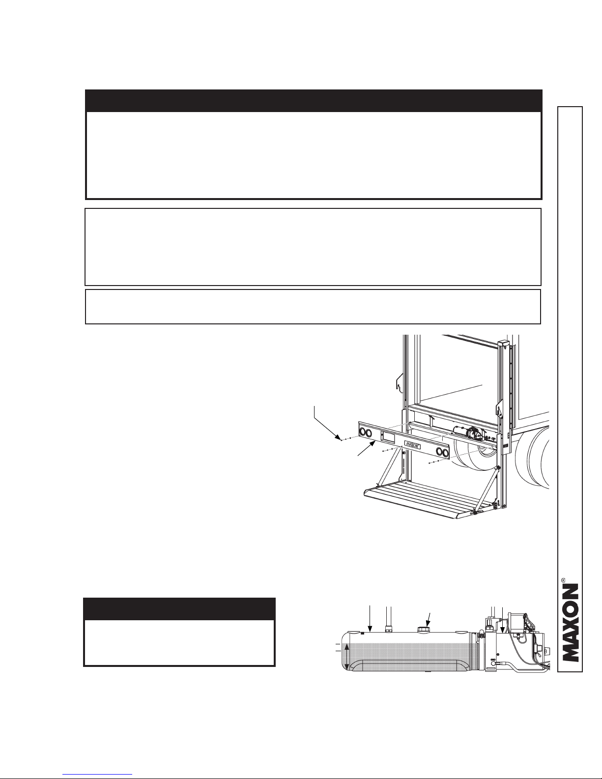
1. Open and lower platform to the
ground (FIG. 11-1). Refer to
Operation Manual for detailed
operating instructions.
2. Unbolt main housing cover
as shown in FIG. 11-1.
Remove cover.
BOLT,
LOCK WASHER &
FLAT WASHER
(3 PLACES)
3. Check the hydraulic fl uid level in
reservoir as follows. With platform
on the ground, level should be as
shown in FIG. 11-2.
4. If needed, add fl uid to the reservoir as
follows. Remove fi ller cap (FIG. 11-2).
Fill the reservoir with hydraulic fl uid to
level shown in FIG. 11-2. Reinstall fi ller
cap.
CAUTION
Main housing cover must be
correctly secured to prevent it
from becoming a hazard.
5. Bolt on the main housing cover
as shown in FIG. 11-1. Torque
the 5/16”-18 cover bolts from 10
to 14 lb-ft.
COVER
UNBOLTING/ BOLTING COVER
(PLATFORM ON THE GROUND)
FIG. 11-1
POWER UNIT
3-3/4” MAX
3-1/4” MIN
RESERVOIR
POWER UNIT FLUID LEVEL
FILLER CAP
(MANUAL CLOSE POWER UNIT SHOWN)
FIG. 11-2
11
11921 Slauson Ave. Santa Fe Springs, CA. 90670 (800) 227-4116 FAX (888) 771-7713
(REF)
Page 12
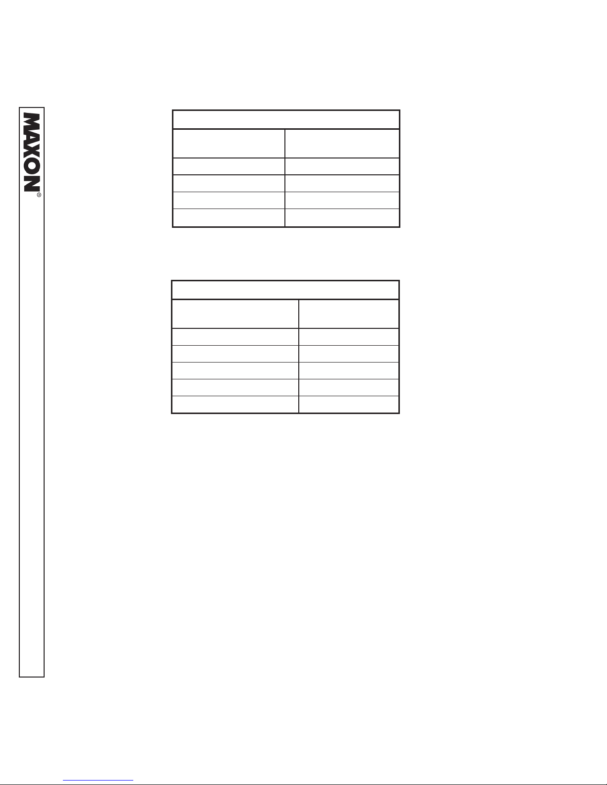
ISO 32 HYDRAULIC OIL
11921 Slauson Ave. Santa Fe Springs, CA. 90670 (800) 227-4116 FAX (888) 771-7713
RECOMMENDED
BRANDS
CHEVRON HIPERSYN 32
KENDALL GOLDEN MV
SHELL TELLUS S2 VX 32
EXXONMOBIL UNIVIS N-32, DTE-24
PART NUMBER
TABLE 12-1
ISO 15 OR MIL-H-5606 HYDRAULIC OIL
RECOMMENDED
BRANDS
CHEVRON FLUID A, AW-MV-15
KENDALL GLACIAL BLU
SHELL TELLUS S2 VX 15
EXXONMOBIL UNIVIS HVI-13
ROSEMEAD THS FLUID 17111
PART NUMBER
TABLE 12-2
12
Page 13

PERIODIC MAINTENANCE
CHANGING HYDRAULIC FLUID
CAUTION
Keep dirt, water and other contaminants from entering the hydraulic system.
Before opening the hydraulic fl uid reservoir fi ller cap, drain plug and hydraulic
lines, clean up contaminants that can get in the openings. Also, protect the
openings from accidental contamination.
Never mix synthetic fl uids with conventional hydraulic fl uids. Hydraulic system
must be purged if the fl uids are mixed.
NOTE: Liftgate is shipped with Exxon Univis HVI-13 hydraulic fl uid in the hydraulic
cylinders. Exxon Univis HVI-13 hydraulic fl uid is recommended for operating
temperatures of -40 to +120° F. Refer to decal in pump box. Under certain
conditions, other brands and grades of oil may be used as substitutes for the
recommended oil. Refer to TABLES 12-1 & 12-2.
1. Open and lower platform to the
ground (FIG. 13-1). Refer to
Operation Manual for detailed
operating instructions.
BOLT,
LOCK WASHER &
FLAT WASHER
(3 PLACES)
2. Unbolt main housing cover
as shown in FIG. 13-1.
Remove cover.
3. Remove drain plug (FIG. 13-2).
Then, drain hydraulic fl uid from
reservoir.
4. Reinstall drain plug (FIG. 13-2).
Then, add new Univis HVI-13
hydraulic fl uid to level shown in
FIG. 13-2.
5. Remove fi ller cap (FIG. 13-2).
Then, add new Univis HVI-13
hydraulic fl uid to level shown in
FIG. 13-2. Reinstall fi ller cap.
COVER
UNBOLTING COVER
(PLATFORM ON THE GROUND)
FIG. 13-1
POWER UNIT
(REF)
3-3/4” MAX
3-1/4” MIN
RESERVOIR
DRAIN PLUG
POWER UNIT FLUID LEVEL
FILLER CAP
(MANUAL CLOSE POWER UNIT SHOWN)
FIG. 13-2
11921 Slauson Ave. Santa Fe Springs, CA. 90670 (800) 227-4116 FAX (888) 771-7713
13
Page 14

6. Raise platform to bed height (FIG. 14-1).
Continue to hold UP/DOWN control
switch for 30 - 60 seconds to circulate
hydraulic fl uid through slave cylinder
and reservoir (FIG. 14-2). Release UP/
DOWN control switch.
11921 Slauson Ave. Santa Fe Springs, CA. 90670 (800) 227-4116 FAX (888) 771-7713
NOTE: Three cycles of draining, fi lling,
and circulating hydraulic fl uid
should be enough to fi ll the sys-
tem with new hydraulic fl uid.
UP/DOWN
CONTROL
SWITCH
PLATFORM AT BED HEIGHT
FIG. 14-1
7. Repeat instructions 1 through 5,
two times. Keep the platform open
and cover removed.
8. Lower platform to the
ground (FIG. 14-3).
CAUTION
Main housing cover must be
correctly secured to prevent it
from becoming a hazard.
POWER UNIT
(REF)
RESERVOIR
POWER UNIT
(MANUAL CLOSE POWER UNIT SHOWN)
FIG. 14-2
BOLT,
LOCK WASHER &
FLAT WASHER
(3 PLACES)
COVER
9. Bolt on the main housing cover
as shown in FIG. 14-3. Torque
the 5/16”-18 cover bolts from
10 to 14 lb-ft.
14
BOLTING ON COVER
FIG. 14-3
Page 15

PERIODIC MAINTENANCE
PRESSURIZING HYDRAULIC SYSTEM
!
CAUTION
Operating Liftgate, under certain conditions, with air in system could result in
damage to lift and load as well as personal injury. If lines are opened & closed
or replaced, and if power unit or cylinders are replaced, pressurize hydraulic
system before operating Liftgate with a passenger or load.
NOTE: When pump pressurizes fl uid in hydraulic system, air is bled into reservoir
through slave cylinder return line.
To pressurize lifting cylinders,
hold outboard control switch in
UP position for 30 - 60 seconds (FIG. 15-1). Then, release toggle switch.
CONTROL SWITCH
FIG. 15-1
OUTBOARD
(UP)
11921 Slauson Ave. Santa Fe Springs, CA. 90670 (800) 227-4116 FAX (888) 771-7713
15
Page 16

REPLACE LH TORSION BAR
Ensure platform is latched securely in stowed
position to release most tension from torsion
bar(s) and keep platform from suddenly unfolding. Injury could result from unbolting the
11921 Slauson Ave. Santa Fe Springs, CA. 90670 (800) 227-4116 FAX (888) 771-7713
torsion bar(s) under tension. When all tension
is released from torsion bar(s), platform can
unfold suddenly. Any person in the path of
opening platform could be injured.
TORSION BAR REPLACEMENT & ADJUSTMENT
!
WARNING
PLATFORM
1. Stow platform (FIG. 16-1). Ensure
platform is latched securely. Refer
to Operation Manual for detailed
operating instructions.
2. Support platform and fl ipover evenly
by placing supports under the RH
and LH runners (FIG. 16-1).
3. Remove cap screw and washers from
torsion bar pin (FIG. 16-2). Initial torsion
bar tension is removed when torsion bar
pin is in position shown in FIG. 16-2A.
FLAT WASHER
(2 PLACES)
LOCK WASHER
CAP SCREW,
1/2”
TORSION
BAR PIN
LH RUNNER
SUPPORT
(2 PLACES)
RH RUNNER
FIG. 16-1
TORSION
BAR PIN
FIG. 16-2A
REMOVING INITIAL TENSION FROM LH TORSION BAR
FIG. 16-2
16
Page 17

PERIODIC MAINTENANCE
TORSION BAR REPLACEMENT & ADJUSTMENT - Continued
4. With platform securely supported,
remove cover plate (FIG. 17-1).
5. Loosen locking screw from LH
torsion bar housing (FIG. 17-2).
PLATFORM
TAPPING
SCREWS
(8 PLACES)
COVER
PLATE
REMOVING COVER PLATE
FIG. 17-1
LH TORSION
BAR HOUSING
LH TORSION
BAR
LOCKING
SCREW
11921 Slauson Ave. Santa Fe Springs, CA. 90670 (800) 227-4116 FAX (888) 771-7713
FIG. 17-2
17
Page 18

TORSION BAR REPLACEMENT & ADJUSTMENT - Continued
6. Remove LH torsion bar pin (FIG. 18-1).
11921 Slauson Ave. Santa Fe Springs, CA. 90670 (800) 227-4116 FAX (888) 771-7713
FLAT WASHER
(2 PLACES)
CAP SCREW,
1/2”
LOCK WASHER
TORSION BAR
PIN
REMOVING LH TORSION BAR PIN
FIG. 18-1
7. Remove LH torsion bar (FIG. 18-2).
LH TORSION
BAR
REMOVING LH TORSION BAR
FIG. 18-2
18
Page 19

ADJUST LH TORSION BAR
WARNING
!
Platform can unfold suddenly with no tension on torsion bar. Stay out of the
path of unfolding platform when adjusting the torsion bar. Get second person
to help unlatch platform.
1. Stow platform. Refer to Operation
Manual for detailed operating
instructions.
TORSION
BAR PIN
2. On LH runner, remove cap screw, lock
washer and fl at washers from torsion bar pin
(FIG. 19-1). Adjust the LH torsion bar pin
counter-clockwise until tension is applied to
torsion bar (FIG. 19-1A). Replace cap screw,
lock washer and fl at washers (FIG. 19-1) and
tighten.
FIG. 19-1A
FLAT WASHER
(2 PLACES)
LOCK WASHER
CAP SCREW,
1/2”
TORSION
BAR PIN
11921 Slauson Ave. Santa Fe Springs, CA. 90670 (800) 227-4116 FAX (888) 771-7713
INCREASING TENSION
FIG. 19-1
19
Page 20

TORSION BAR REPLACEMENT & ADJUSTMENT - Continued
3. Unlatch platform (FIG. 20-1).
Platform should just escape the latch
as shown in FIG. 20-1, position 1.
4. Unfold platform until latch pin is 2”-3” from
latch (FIG. 20-1, position 2). Release
hold on platform. Observe If platform starts
to fold, stays partially unfolded, or starts
11921 Slauson Ave. Santa Fe Springs, CA. 90670 (800) 227-4116 FAX (888) 771-7713
falling open with no restraint. Platform
should unfold slowly when released (FIG.
20-1, position 3). To increase the amount
of pull, adjust the torsion bar pin counter clockwise until increased tension is applied
to torsion bar (FIG. 19-1). Once the platform
is unfolded, it should lay fl at (FIG. 20-1,
position 3). If platform does not lay fl at,
decrease tension by removing cap screw,
lock washer and fl at washers from LH
torsion bar pin (FIG. 20-2). Adjust torsion
bar pin clockwise until tension is decreased
(FIG. 20-2A). Replace cap screw, lock
washer and fl at washers (FIG. 20-2)
and tighten.
3
FLAT WASHER
(2 PLACES)
CAP SCREW,
1/2”
2
1
FIG. 20-1
LOCK WASHER
TORSION
BAR PIN
5. If additional tension is needed,
stow platform (FIG. 20-3). Ensure
platform is latched securely. Refer
to Operation Manual for detailed
operating instructions.
6. Support platform and fl ipover evenly
by placing supports under the RH
and LH runners (FIG. 20-3).
FIG. 20-2A
LH RUNNER
SUPPORT
(2 PLACES)
20
TORSION
BAR PIN
DECREASING TENSION
FIG. 20-2
PLATFORM
RH RUNNER
FIG. 20-3
Page 21

TORSION BAR REPLACEMENT & ADJUSTMENT - Continued
7. With platform securely supported,
remove cover plate (FIG. 21-1).
8. Loosen locking screw from LH
torsion bar housing (FIG. 21-2).
PLATFORM
TAPPING
SCREWS
(8 PLACES)
COVER
PLATE
REMOVING COVER PLATE
FIG. 21-1
LH TORSION
BAR HOUSING
LH TORSION
BAR
LOCKING
SCREW
11921 Slauson Ave. Santa Fe Springs, CA. 90670 (800) 227-4116 FAX (888) 771-7713
FIG. 21-2
21
Page 22

TORSION BAR REPLACEMENT & ADJUSTMENT - Continued
9. Increase LH torsion bar
tension by moving LH torsion
bar housing inboard towards
center of vehicle (FIG. 22-1).
Approximate adjustment
travel should be no more than
10”.
11921 Slauson Ave. Santa Fe Springs, CA. 90670 (800) 227-4116 FAX (888) 771-7713
STOP BLOCK
0”- 10”
LH TORSION
BAR HOUSING
INCREASING LH TORSION BAR TENSION
FIG. 22-1
10. Replace and tighten LH
torsion bar housing locking
screw (FIG. 22-2).
LH TORSION
BAR
LOCKING
SCREW
11. Platform can be stowed or returned
to operation after adjustment is
done correctly.
LH TORSION
BAR HOUSING
FIG. 22-2
22
Page 23

PERIODIC MAINTENANCE
TORSION BAR REPLACEMENT & ADJUSTMENT - Continued
REPLACE RH TORSION BAR (IF EQUIPPED)
1. Stow platform. Refer to Operation
Manual for detailed operating
instructions.
2. Support platform and fl ipover evenly
by placing supports under the RH
and LH runners (FIG. 23-1).
3. With platform securely supported,
remove cover plate (FIG. 23-2).
SUPPORT
(2 PLACES)
FIG. 23-1
PLATFORM
(8 PLACES)
REMOVING COVER PLATE
FIG. 23-2
TAPPING
SCREWS
COVER
PLATE
11921 Slauson Ave. Santa Fe Springs, CA. 90670 (800) 227-4116 FAX (888) 771-7713
23
Page 24

TORSION BAR REPLACEMENT & ADJUSTMENT - Continued
4. Loosen locking screw from RH
torsion bar housing (FIG. 24-1).
11921 Slauson Ave. Santa Fe Springs, CA. 90670 (800) 227-4116 FAX (888) 771-7713
5. On RH runner, unbolt the platform and
runner pin from RH runner (FIG. 24-2). Next,
remove platform and runner pin, and platform
spacer (FIG. 24-2).
RH TORSION
BAR HOUSING
LOCKING
SCREW
RH TORSION
BAR
FIG. 24-1
PLATFORM &
RUNNER PIN
RH RUNNER
LOCK
WASHERS
6. Remove RH torsion bar (FIG.24-3).
PLATFORM
SPACER
RH TORSION
BAR
RH TORSION
BAR
CAP
SCREW
(2 PLACES)
FIG. 24-2
24
REMOVING RH TORSION BAR
FIG. 24-3
Page 25

TORSION BAR REPLACEMENT & ADJUSTMENT - Continued
7. With platform in vertical
position, insert the torsion bar
into the RH platform and
runner pin, through RH
runner, platform spacer and
engage with RH torsion bar
housing (FIG. 25-1).
RH RUNNER
RH TORSION
BAR HOUSING
PLATFORM
SPACER
RH TORSION
BAR
PLATFORM &
RUNNER PIN
LOCK
WASHERS
CAP
SCREW
(2 PLACES)
8. Rotate the RH platform and
runner pin clockwise to line
up the pin holes with the RH
runner threaded holes (FIG.
25-2).
9. Secure RH platform and
runner pin as shown in FIG.
25-2.
10. Ensure platform is latched
securely in stow position. Then,
remove platform supports.
RH RUNNER
THREADED HOLES
FIG. 25-1
LOCK
WASHERS
(2 PLACES)
CAP
SCREW
(2 PLACES)
RH PIN
WELDMENT
FIG. 25-2
11921 Slauson Ave. Santa Fe Springs, CA. 90670 (800) 227-4116 FAX (888) 771-7713
25
Page 26

DECALS
NOTE: Decals are preinstalled at factory.
Decal location shown for reference.
NOTE: Ensure there is no residue, dirt or
corrosion where decals are attached.
If necessary, clean surface before
replacing decals.
11921 Slauson Ave. Santa Fe Springs, CA. 90670 (800) 227-4116 FAX (888) 771-7713
DECAL “F” OR “G”
DMD-22 ONLY
CAPACITY DECAL
P/N 220388-03
DMD-33 ONLY
CAPACITY DECAL
P/N 220388-02
DECAL “E”
DECAL “D”
WARNING DECAL
P/N 298373-01
DECAL “B”
DECAL “A”
DECAL “C”
WARNING DECAL
P/N 299274-01
FAMILY OWNED DECAL
P/N 283445-01
COLUMN ARROW
DECAL “H”
P/N 289192-01
RUNNER ARROW
DECAL “H”
P/N 289192-01
26
Page 27

DECAL SHEET
P/N 289192-01
11921 Slauson Ave. Santa Fe Springs, CA. 90670 (800) 227-4116 FAX (888) 771-7713
WARNING DECAL
P/N 298373-01
WARNING DECAL
P/N 299274-01
27
Page 28

PUMP MOTOR & VALVE OPERATION (MANUAL CLOSE)
11921 Slauson Ave. Santa Fe Springs, CA. 90670 (800) 227-4116 FAX (888) 771-7713
SYSTEM DIAGRAMS
LOWERING
VALVE
STARTER
SWITCH
MOTOR
POWER UNIT
FIG. 28-1
POWER UNIT MOTOR & SOLENOID OPERATION
SOLENOID OPERATION
LIFTGATE
FUNCTION
RAISE -
LOWER -
REFER TO VALVES SHOWN ON
HYDRAULIC SCHEMATIC
( MEANS ENERGIZED)
MOTOR
STARTER
SWITCH
LOWERING
VALVE
TABLE 28-1
28
Page 29

PUMP MOTOR & VALVE OPERATION
(EQUIPPED WITH HYDRAULIC CLOSER)
LOWERING
VALVE
POWER UNIT MOTOR & VALVE OPERATION
LIFTGATE
FUNCTION
STARTER
SWITCH
POWER UNIT
REMOTE VALVE OPERATION
MOTOR
MOTOR
FIG. 29-1
( MEANS ENERGIZED)
LOWERING
VALVE
FOLD/UNFOLD
FOLD/UNFOLD VALVE
ASSEMBLY
VALVE
RAISE
LOWER
UNFOLD
FOLD
11921 Slauson Ave. Santa Fe Springs, CA. 90670 (800) 227-4116 FAX (888) 771-7713
REFER TO VALVES SHOWN ON
HYDRAULIC SCHEMATIC
TABLE 29-1
29
Page 30

11921 Slauson Ave. Santa Fe Springs, CA. 90670 (800) 227-4116 FAX (888) 771-7713
HYDRAULIC SCHEMATIC (MANUAL CLOSE)
3.0
FIG. 30-1
30
Page 31

HYDRAULIC SCHEMATIC (EQUIPPED WITH HYDRAULIC CLOSER)
3.0
11921 Slauson Ave. Santa Fe Springs, CA. 90670 (800) 227-4116 FAX (888) 771-7713
FIG. 31-1
31
Page 32

11921 Slauson Ave. Santa Fe Springs, CA. 90670 (800) 227-4116 FAX (888) 771-7713
ELECTRICAL SCHEMATIC (MANUAL CLOSE)
FIG. 32-1
32
Page 33

ELECTRICAL SCHEMATIC (EQUIPPED WITH HYDRAULIC CLOSER)
11921 Slauson Ave. Santa Fe Springs, CA. 90670 (800) 227-4116 FAX (888) 771-7713
FIG. 33-1
33
Page 34

ELECTRICAL SCHEMATIC - JUMPER HARNESS ASSEMBLY
CONNECT TERMINALS TO
VEHICLE HARNESS
11921 Slauson Ave. Santa Fe Springs, CA. 90670 (800) 227-4116 FAX (888) 771-7713
TERMINAL “A” GROUND
TERMINAL “B” TAIL
TERMINAL “C” REVERSE
ORANGE
BLACK
WHITE
GREEN
RED
YELLOW
TERMINAL “F” LH STOP/TURN
TERMINAL “E” RH STOP/TURN
TERMINAL “D” STOP
CONNECT MALE TERMINAL TO
COVER LIGHTS HARNESS
FOREIGN/DOMESTIC
FIG. 34-1
CONNECT TERMINALS TO
VEHICLE HARNESS
ORANGE
BLACK
WHITE
TERMINAL “A” GROUND
TERMINAL “B” TAIL
TERMINAL “C” REVERSE
CONNECT MALE TERMINAL TO
COVER LIGHTS HARNESS
ISUZU
FIG. 34-2
34
GREEN
RED
YELLOW
TERMINAL “F” LH STOP/TURN
TERMINAL “E” RH STOP/TURN
TERMINAL “D” STOP
Page 35

SYSTEM DIAGRAMS
ELECTRICAL SCHEMATIC - HOUSING COVER ASSEMBLY
(WITHOUT LIGHTS)
CONNECT TO
WIRING HARNESS
LICENSE PLATE
LIGHT
LH LICENSE PLATE
LIGHT
RH LICENSE PLATE
LIGHT
11921 Slauson Ave. Santa Fe Springs, CA. 90670 (800) 227-4116 FAX (888) 771-7713
FIG. 35-1
35
Page 36

ELECTRICAL SCHEMATIC - HOUSING COVER ASSEMBLY
11921 Slauson Ave. Santa Fe Springs, CA. 90670 (800) 227-4116 FAX (888) 771-7713
(WITH FOUR LIGHTS)
CONNECT TO
JUMPER HARNESS
36
CONNECT TO
VEHICLE HARNESS
Page 37

SYSTEM DIAGRAMS
ELECTRICAL SCHEMATIC - HOUSING COVER ASSEMBLY,
FOREIGN VEHICLE (WITH 6 LIGHTS )
CONNECT TO
JUMPER HARNESS
37
CONNECT TO
VEHICLE HARNESS
11921 Slauson Ave. Santa Fe Springs, CA. 90670 (800) 227-4116 FAX (888) 771-7713
Page 38

SYSTEM DIAGRAMS
DMD ELECTRICAL VALUES
SOLENOID SWITCH 12V 24V
Coil Resistance:
Ampere:
Coil terminal torque: 10-15 lb-in max.
11921 Slauson Ave. Santa Fe Springs, CA. 90670 (800) 227-4116 FAX (888) 771-7713
Contact terminal torque: 30-35 lb-in max.
Coil Resistance:
Ampere:
Coil terminal torque: 15-45 lb-in max.
Valve cartridge torque: 25-30 lb-ft max.
Coil nut torque: 15-45 lb-in
FOLD/UNFOLD VALVE
Coil Resistance:
Ampere:
5.4Ω @70ºF. ±15% 20.1Ω @70ºF. ±15%
2.2A 1.2A
LOWERING VALVE
6.6Ω @ 70ºF. ±15% 26.7Ω @ 70ºF. ±15%
1.8A 0.9A
8.0Ω @ 70ºF. ±15% 30Ω @ 70ºF. ±15%
1.5A 0.8A
Coil terminal torque: 3-4.5 lb-ft max.
Valve cartridge torque: 18.5-22 lb-ft max.
GROUND CABLE
Cap Screw Torque: 24 lb-ft max.
CYCLE COUNTER
Operation Voltage:
TABLE 38-1
7V - 30V 7V - 30V
38
Page 39

RECOMMENDED BOLT TORQUES
CAUTION
The torque values in the following table are provided for torquing grade 8
bolts on Liftgate mechanical parts. To prevent damage, never use the information in this table for torquing electrical or hydraulic hose connections on
the pump assembly.
GRADE 8 BOLT TIGHTENING TORQUE
DIAMETER & THREAD PITCH TORQUE
1/4”-20 10-14 lb-ft
1/4”-28 11-16 lb-ft
5/16”-18 20-29 lb-ft
5/16”-24 22-33 lb-ft
3/8”-16 35-52 lb-ft
3/8”-24 40-59 lb-ft
7/16”-14 56-84 lb-ft
7/16”-20 62-93 lb-ft
1/2”-13 85-128 lb-ft
1/2”-20 96-144 lb-ft
9/16”-12 123-184 lb-ft
9/16”-18 137-206 lb-ft
5/8”-11 170-254 lb-ft
5/8”-18 192-288 lb-ft
3/4”-10 301-451 lb-ft
3/4”-18 336-504 lb-ft
TABLE 39-1
11921 Slauson Ave. Santa Fe Springs, CA. 90670 (800) 227-4116 FAX (888) 771-7713
39
Page 40

 Loading...