

Page 1
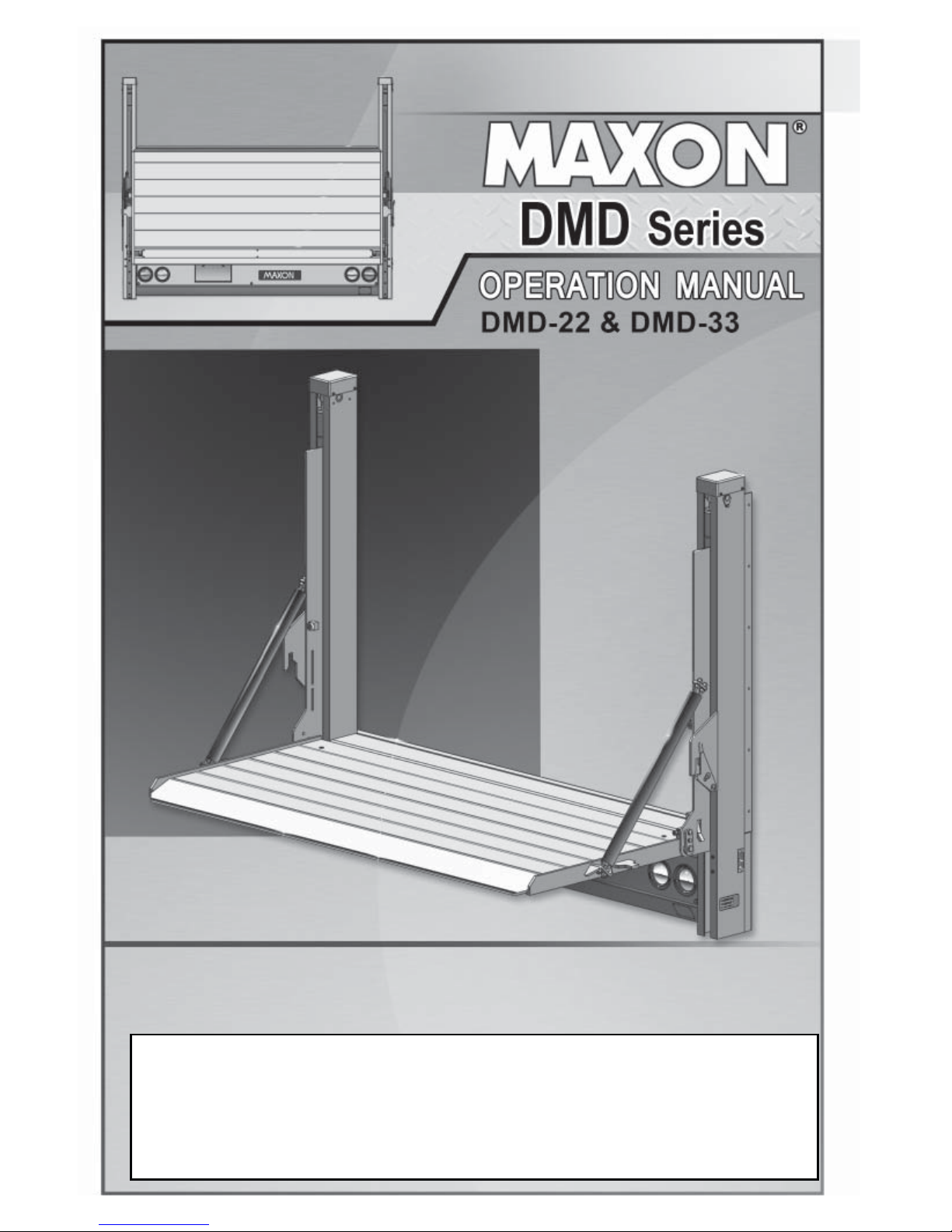
© MAXON Lift Corp. 2018
To fi nd maintenance & parts information for your DMD Liftgate, go to
www.maxonlift.com. Click the PRODUCTS, RAILIFT & DMD buttons.
Open the Maintenance Manual in the PRODUCT DOCUMENTATION
window.
To fi nd maintenance & parts information for your DMD Liftgate, go
to www.maxonlift.com. Click the PRODUCTS, RAILIFT & DMD
buttons. Open the Maintenance Manual in the PRODUCT DOCU-
MENTATION window. For parts, click on the PARTS PORTAL,
RAILIFT & DMD buttons.
M-16-39
JUNE 2018
Page 2

Page 3

TABLE OF CONTENTS
WARNINGS ..............................................................................5
LIFTGATE TERMINOLOGY .....................................................6
DECALS & PLATES ...............................................................7
FORKLIFT ADVISORY ............................................................9
OPERA TION ............................................................................10
UNFOLDING THE PLA TFORM ................................................10
LOADING VEHICLE .................................................................14
LOWERING THE PLA TFORM .................................................14
POSITIONING LOAD ...............................................................14
RAISING & UNLOADING PLATFORM .....................................15
UNLOADING VEHICLE ............................................................16
LOWERING THE PLA TFORM .................................................16
RAISING THE PLA TFORM ......................................................16
POSITIONING LOAD ...............................................................17
LOWERING & UNLOADING PLATFORM ................................18
STOWING PLATFORM ............................................................19
USING STANDARD CART STOPS (IF EQUIPPED) ...............22
USING RETENTION RAMP (IF EQUIPPED) ...........................25
Page 4

4
THIS PAGE INTENTIONALLY LEFT BLANK
Page 5

5
WARNINGS
2. Do not exceed rated load capacity of 2200 lb for DMD-22 Liftgate,
and 3300 lb for DMD-33 Liftgate.
3. Do not allow any part of your body to be placed under, within, or
around any portion of the moving Liftgate or its mechanisms, or in
a position that would trap them between the platform and the fl oor
of truck body (or between platform and the ground) when Liftgate
is operated.
4. Consider the safety and location of bystanders and
location of nearby objects when operating the Liftgate. Stand
to one side of platform while operating the Liftgate. Be certain
that the area the Liftgate will move through during operation
is clear of all obstacles.
5. Comply with all attached instruction decals and warning decals.
11. Above all, USE GOOD COMMON SENSE when operating this
Liftgate.
8. Do not move vehicle unless Liftgate is correctly stowed.
6. Keep decals clean and legible. If decals are illegible or missing,
have them replaced. Get free replacement decals from Maxon.
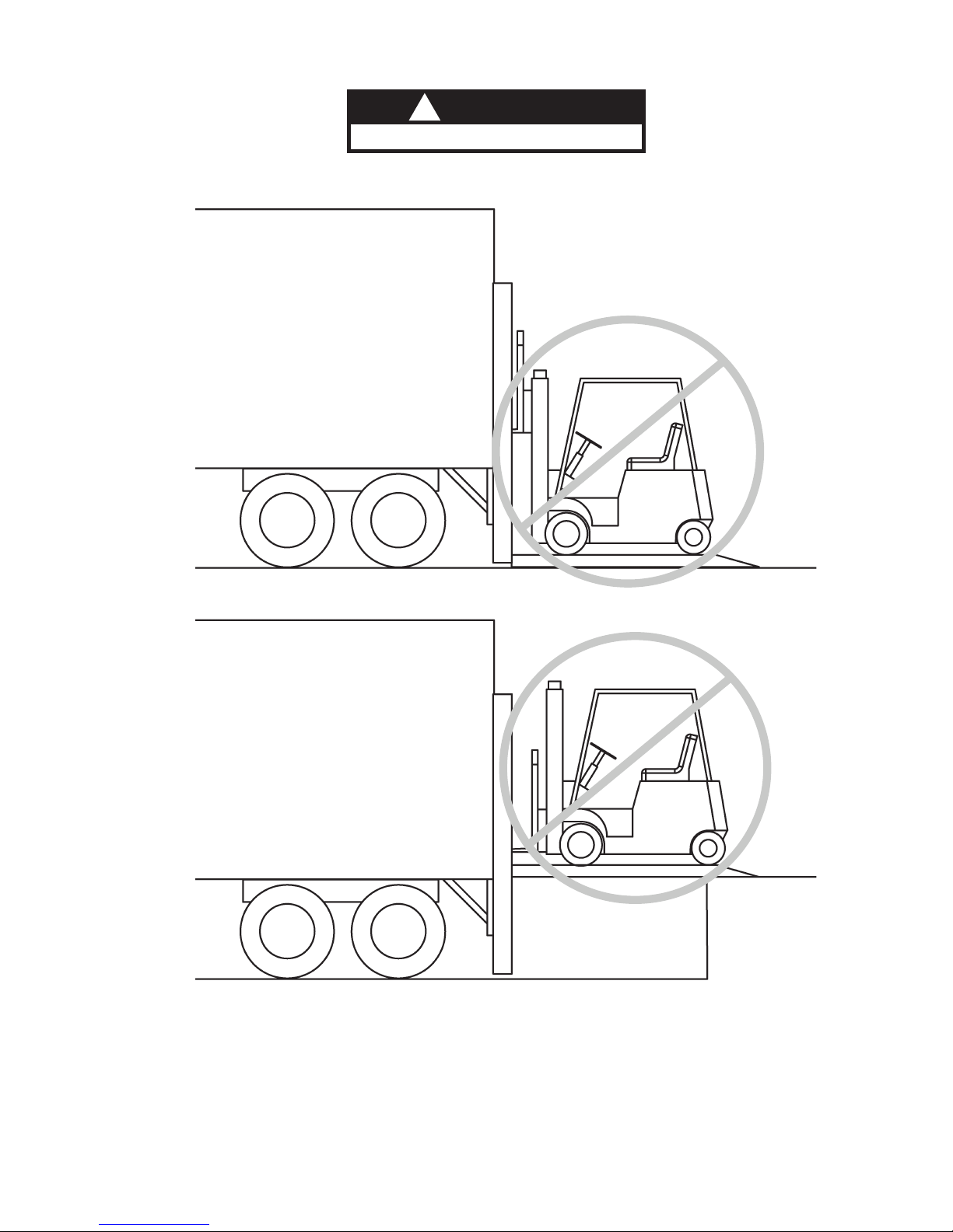
7. Never drive a forklift on the Liftgate platform.
10. A correctly installed Liftgate will operate smoothly and reasonably
quiet. The only noticeable noise during Liftgate operation is from
the power unit while the platform is being lowered and raised. Listen for scraping, grating and binding noises and have the problem
corrected before continuing to operate the Liftgate.
MAXON Lift Corp. Customer Service
11921 Slauson Ave
Santa Fe Springs, CA 90670
(800) 227-4116
WARNING
!
9. Correctly stow platform when not in use. Extended platforms
could create a hazard for people and vehicles passing by.
1. Incorrect operation of this Liftgate can result in serious personal
injury. Comply with WARNINGS and Liftgate operating instructions
in this manual. Do not allow untrained persons or children to oper-
ate the Liftgate. If you need to replace an Operation Manual, additional copies are available from:
12. Never use a cell phone while operating the Liftgate.
Page 6
6
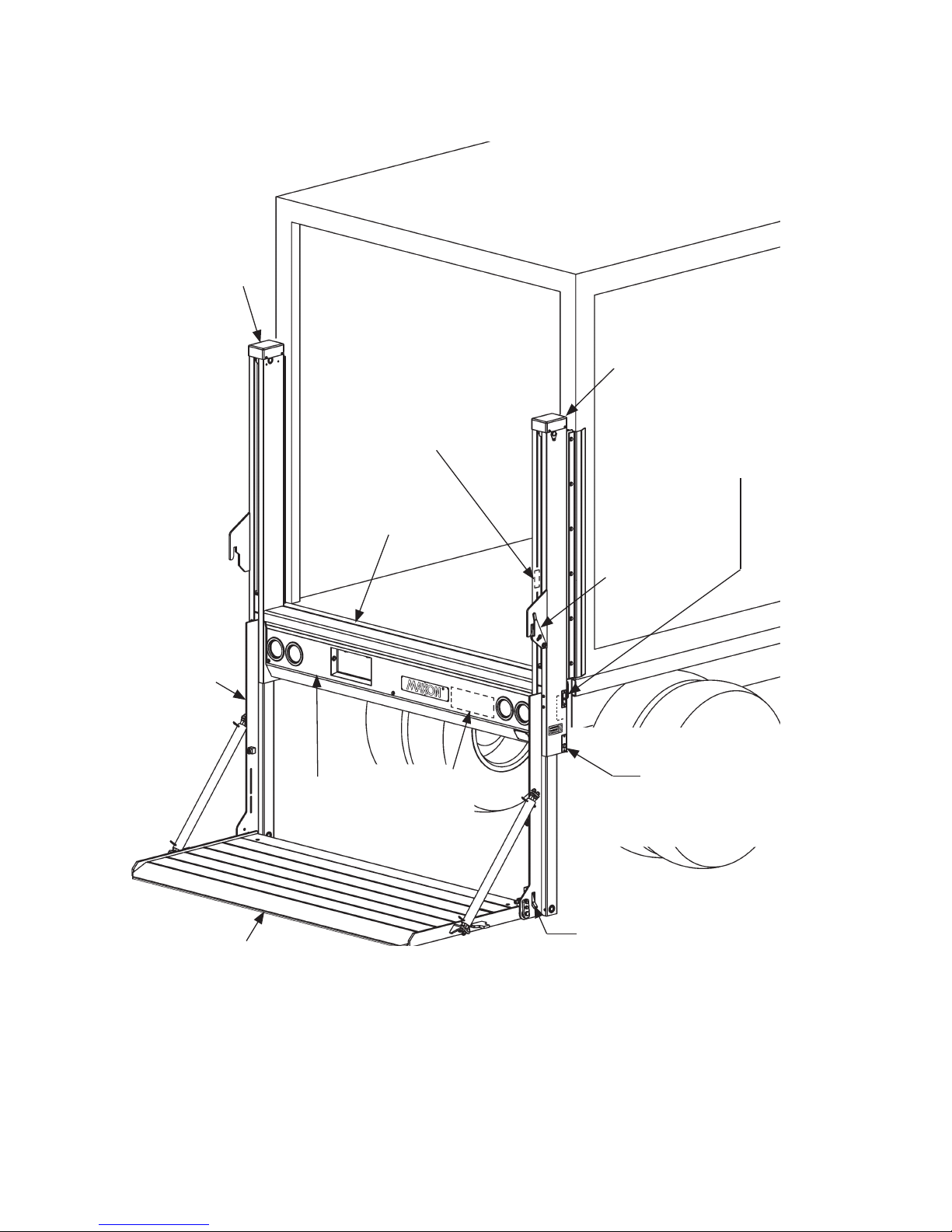
LIFTGATE TERMINOLOGY
RUNNER
PLATFORM
LH COLUMN
MAIN FRAME
HOUSING
COVER
LOCK
POWER
UNIT
(BEHIND
COVER)
UP/DOWN
CONTROL SWITCH
(OUTBOARD)
UP/DOWN
CONTROL SWITCH
(INBOARD)
TRANSIT
HOOK
FOLD/UNFOLD
SWITCH
(IF EQUIPPED WITH
HYDRAULIC CLOSER)
RH COLUMN
Page 7
7
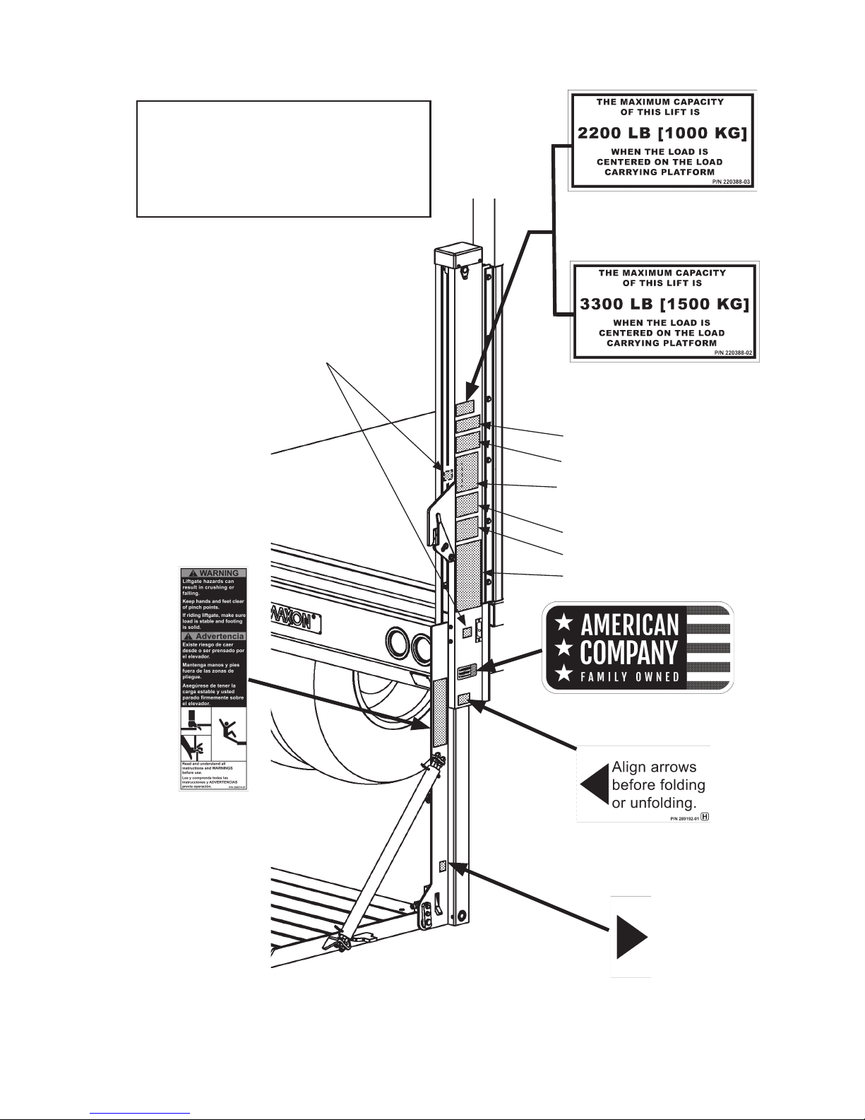
DECALS & PLATES
DECAL “E”
DECAL “D”
DECAL “B”
DECAL “A”
NOTE: Ensure there is no residue,
dirt, or corrosion where
decals are attached. If
necessary, clean surface
before attaching decals.
FAMILY OWNED DECAL
P/N 283445-01
WARNING DECAL
P/N 298373-01
DECAL “C”
DECAL “F” OR “G”
DMD-22 ONLY
CAPACITY DECAL
P/N 220388-03
DMD-33 ONLY
CAPACITY DECAL
P/N 220388-02
WARNING DECAL
P/N 299274-01
COLUMN ARROW
DECAL “H”
P/N 289192-01
RUNNER ARROW
DECAL “H”
P/N 289192-01
Page 8
8
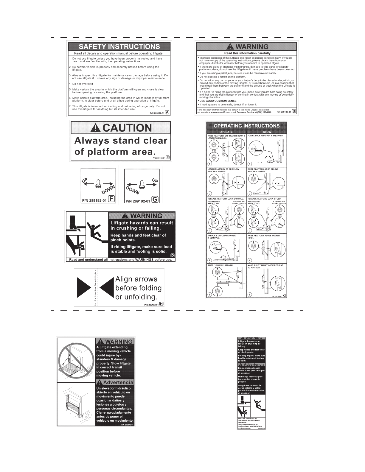
DECALS
DECAL SHEET
P/N 289192-01
WARNING DECAL
P/N 298373-01
WARNING DECAL
P/N 299274-01
Page 9
9
Keep forklift OFF of platform.
FORKLIFT ADVISOR Y
FIG. 9-1
FIG. 9-2
WARNING
!
Page 10

10
1. Raise platform stop off transit
hook (FIG. 10-1A) by pushing the
outboard control switch to (UP)
position (FIG. 10-1).
UNFOLDING THE PLATFORM
OUTBOARD CONTROL
SWITCH (UP)
OPERATION
TRANSIT
HOOK
PLATFORM
FIG. 10-1
PLATFORM
STOP
FIG. 10-1A
Page 11

11
2. Rotate transit hook away
from platform stop (FIG.
11-1A). Push outboard
control switch DOWN (FIG.
11-1) to lower the platform
slightly until platform stop
clears transit hook.
FIG. 11-1
TRANSIT HOOK
PLATFORM
STOP
PLATFORM
FIG. 11-1A
OUTBOARD
CONTROL
SWITCH (DOWN)
Page 12

12
3. For manual close Liftgate, push platform lock
up to unlock the platform (FIG. 12-1A).
Manually unfold platform (FIG. 12-1). Next,
push platform lock down to lock
platform (FIG. 12-1B).
UNFOLDING PLATFORM
(MANUAL CLOSE)
FIG. 12-1
FIG. 12-1A
PLATFORM
LOCK
FIG. 12-1B
PLATFORM
LOCK
UNFOLDING THE PLATFORM - Continued
PLATFORM
NOTE: If platform is
equipped with hydraulic
closer, do step 4.
Page 13

13
4. For Liftgate equipped with hydraulic closer, hold power
closer switch (FIG. 15-1) and lower outboard control
switch (DOWN) at the same time to unfold platform
(FIG. 13-1).
5. Unlock and unfold fl ipover (if equipped)
(FIG. 13-2).
FLIPOVER
UNFOLDING FLIPOVER
FIG. 13-2
LATCH
UNFOLDING PLATFORM
(EQUIPPED WITH HYDRAULIC CLOSER)
FIG. 13-1
POWER CLOSER
SWITCH (UNFOLD)
OUTBOARD CONTROL
SWITCH (DOWN)
PLATFORM
LOCK
Page 14

14
Place all loads as close as
possible to the inboard edge of
the platform with heaviest part
toward the truck body as shown
in FIG. 14-2. Move loads across
the ramp (FIG. 14-2) to the
platform, but never rest or raise
loads on the ramp. If standing
on platform with the load, stand
in the footprint area shown
and comply with the preceding
WARNING.
A load should never extend past the edges of the platform. Do not
place unstable loads on platform and do not allow load to exceed
lifting capacity of Liftgate. If standing on platform, do not allow your
feet to extend beyond inboard edge of platform.
WARNING
!
LOADING PLATFORM AT GROUND LEVEL
FIG. 14-2
LOADING VEHICLE
POSITIONING LOAD
LOWERING THE PLATFORM
Use outboard control switch
to lower (DOWN) platform
(FIG. 14-1). Release toggle
switch when platform reaches
the ground.
FIG. 14-1
RAMP
INBOARD
EDGE
OUTBOARD
CONTROL
SWITCH (DOWN)
Page 15

15
2. Carefully move the load
into vehicle (FIG. 15-1).
RAISING & UNLOADING PLATFORM
A ramp in retention position can trip you when stepping over it.
To prevent possible injury, get on the platform before putting the
ramp in retention position.
CAUTION
!
1. Use inboard control switch
to raise (UP) platform from
ground level to bed height
(FIG. 15-1). Release toggle
switch when platform
reaches bed height.
INBOARD CONTROL
SWITCH (UP)
3. Use inboard control
switch to lower (DOWN)
the platform to ground
level (FIG. 15-2).
MOVING LOAD INTO VEHICLE
FIG. 15-1
4. If there are more loads
to put in vehicle, repeat
the previous LOADING
VEHICLE steps for
each load. When
loading is fi nished, use
STOWING PLATFORM
procedure in this
manual.
LOWERING PLATFORM
FIG. 15-2
INBOARD CONTROL
SWITCH (DOWN)
Page 16

16
UNLOADING VEHICLE
LOWERING THE PLATFORM
RAISING THE PLATFORM
Use inboard control switch to
raise (UP) platform (FIG. 16-2)
from ground level to bed height.
Release toggle switch when
platform reaches bed height.
FIG. 16-2
INBOARD CONTROL
SWITCH (UP)
Use inboard control switch
to lower (DOWN) platform
(FIG. 16-1). Release toggle
switch when platform
reaches the ground.
FIG. 16-1
INBOARD CONTROL
SWITCH
(DOWN)
Page 17

17
A load should never extend past the edges of the platform. Do not
place unstable loads on platform and do not allow load to exceed
lifting capacity of Liftgate. If standing on platform, do not allow your
feet to extend beyond inboard edge of platform.
WARNING
!
POSITIONING LOAD
PUSHING LOAD ON PLATFORM
FIG. 17-1
Load the platform at bed level
(FIG. 17-1) as follows. Push load
out of the vehicle to correct position on the platform. Place all loads
as close as possible to the inboard
edge of the platform with heaviest
part toward the vehicle body as
shown in FIG. 17-1. If standing on
platform with the load, stand in the
footprint area shown and comply
with the WARNING at the top
of this page.
Pulling the load from vehicle to platform can result in a fall from
platform and serious injury. When unloading vehicle, always push
the load out on the platform.
!
WARNING
UNLOADING VEHICLE - Continued
INBOARD
EDGE
Page 18

18
1. Use outboard control switch
to lower (DOWN) platform
to the ground (FIG. 18-1).
Release toggle switch
when platform reaches
ground level.
Before lowering platform, make sure area surrounding platform is
clear of people and objects. If standing on platform, do not allow
your feet to extend beyond inboard edge of platform.
WARNING
!
2. Carefully move load off platform
(FIG. 18-2) and then move it to
a place where it will not become
a hazard for people and other
vehicles. If there is more to
unload from vehicle, repeat
the previous UNLOADING
VEHICLE steps for each load.
When unloading is fi nished,
use STOWING PLATFORM
procedure in this manual.
LOWERING & UNLOADING PLATFORM
MOVING LOAD OFF PLATFORM
FIG. 18-2
OUTBOARD
CONTROL
SWITCH
(DOWN)
LOWERING PLATFORM TO GROUND LEVEL
FIG. 18-1
Page 19

19
1. Use outboard control
switch to raise (UP)
platform to comfortable
height (12“ to 18”) above
ground level (FIG. 19-1).
2. Fold and lock fl ipover (if
equipped) (FIG. 19-2).
FIG. 19-1
FIG. 19-2
NOTE: Ensure platform is stowed under hydraulic pressure.
STOWING PLATFORM
FLIPOVER
LOCK
OUTBOARD
CONTROL
SWITCH (UP)
Page 20

20
3. Pull UP on platform lock
(FIG. 20-1A) to unlock
platform. Fold platform
to stowed position (FIG.
20-1). Push platform lock
DOWN to lock platform
(FIG. 20-1B).
FOLDING PLA TFORM
FIG. 20-1
FIG. 20-1A
4. If equipped with hydraulic closer,
(FIG. 20-2) use one hand for
outboard control switch (UP)
(FIG. 20-2A) and one hand
for FOLD/UNFOLD switch
(FIG. 20-2B). Activate FOLD
and UP together until platform
is folded.
STOWING PLATFORM - Continued
FOLDING PLATFORM WITH HYDRAULIC CLOSER
FIG. 20-2
NOTE: If platform is
equipped with hydraulic
closer, do step 4.
Folding the platform with
hydraulic closer requires 2
hands on the controls. This
helps prevent injuries.
CAUTION
!
FOLD/UNFOLD
SWITCH
FIG. 20-2B
OUTBOARD CONTROL
SWITCH (UP)
FIG. 20-2A
PLATFORM
LOCK
FIG. 20-1B
Page 21

21
5. Use outboard control
switch to raise (UP)
platform (FIG. 21-1) to
clear transit hooks (FIG.
21-1A). Final platform
resting position is shown in
FIG. 21-1B.
RAISE PLATFORM
FIG. 21-1
OUTBOARD
CONTROL SWITCH
(UP)
PLATFORM
TRANSIT
HOOK
FIG. 21-1B
FIG. 21-1A
Page 22

22
NOTE: Some Liftgates are equipped with single or dual cart stops.
Cart stops prevent loaded carts from rolling off outboard end
of platform. Single cart stops are 1 section, about the same as
overall width of platform, and operate with one set of controls.
Dual cart stops are 2 identical sections, with a combined
width about the same as overall width of platform, and each
is independently operated with separate controls (1 set of
controls per cart stop). The following procedure shows how to
operate dual cart stops; however, a single cart stop operates
the same way.
CAUTION
!
To prevent injuries caused by tripping and falling, make sure
cart stops are closed before walking on and off outboard end of
platform.
USING STANDARD CART STOPS (IF EQUIPPED)
1. Load a platform with cart stops
at ground level as follows.
Make sure cart stops are
closed when loading the platform (FIGS. 22-1 and 22-2).
Then, move load on the platform as shown in FIG. 22-1.
LOADING PLATFORM AT GROUND LEVEL
(CART STOPS CLOSED)
FIG. 22-1
CLOSING CART STOPS
(RH VIEW OF FLIPOVER)
FIG. 22-2
2. To close cart stops, push
shoot bolt to position shown
in FIG. 22-2. Step on cart
stops and push down into
locked position.
CART STOPS
CART STOP
SHOOT BOLT
Page 23

23
3. To open cart stops, push shoot
bolt in direction shown in FIG.
23-1.
4. Open cart stops (FIGS. 23-1
and 23-2). Next, position cart
and stand in the footprint area
as shown in FIG. 23-2.
CART STOPS OPEN
FIG. 23-2
OPENING CART STOPS
(RH VIEW OF FLIP OVER)
FIG. 23-1
5. Raise the platform to bed
level (FIG. 25-3). Move
the load off the platform
into the vehicle body
(FIG. 25-3).
UNLOADING PLATFORM AT BED LEVEL
FIG. 23-3
CART STOP
PLATFORM
CART STOPS
TRUCK
BODY
INBOARD
EDGE
SHOOT
BOLT
Page 24

24
6. When loading the platform
at bed level, make sure cart
stops are open (FIG. 24-1).
Push load out of the vehicle
to correct position on the
platform. Place all loads
as close as possible to the
inboard edge of the platform
with heaviest part toward the
truck body as shown in FIG.
24-1. If standing on platform
with the load, stand in the
footprint area shown and
comply with the WARNING
on page 19.
Pulling the load from vehicle to platform can result in a fall
from platform and serious injury. When unloading vehicle,
always push the load out on the platform.
WARNING
!
LOADING PLATFORM AT BED LEVEL
(DUAL CART STOPS OPEN)
FIG. 24-1
7. Unload the platform with cart
stops at ground level as follows. Make sure cart stops
are closed when unloading
the platform (FIG. 24-2).
Move cart enough to close
cart stop. Then, move load
off the platform as shown in
FIG. 24-3.
CART STOPS CLOSED
FIG. 24-3
CLOSING CART STOPS
(RH VIEW OF FLIPOVER)
FIG. 24-2
CART
STOPS
USING STANDARD CART STOPS (IF EQUIPPED)
- Continued
PLATFORM
CART
STOPS
INBOARD
EDGE
TRUCK
BODY
CART STOP
SHOOT BOLT
Page 25

25
USING RETENTION RAMP (IF EQUIPPED)
NOTE: Some Liftgates are equipped with a retention ramp. A reten-
tion ramp, like a cart stop, prevents a load from rolling or sliding off outboard end of platform. Unlike a cart stop, a retention
ramp lets you use the entire load surface of platform. The
catches on top of the fl ipover and a cam-like hinge action
keep retention ramp stowed when not in use. The cam-like
hinge also allows the retention ramp to be rotated and locked
in retention position or in ramp position. The following procedure shows how to operate a retention ramp.
CAUTION
!
To prevent injuries caused by tripping and falling, make sure
retention ramp is in the ramp position before walking on and off
outboard end of platform.
FIG. 25-1
RETENTION
RAMP
Page 26

26
To prevent injuries, stay clear of the retention ramp path as it is
moved to ramp position. Go to either side of the ramp and stay
out of the way.
CAUTION
!
NOTE: To unhook the retention ramp, stand at the RH side of
fl ipover. After the retention ramp is unhooked, the recommended place for handling the retention ramp is at the
center of the free edge (FIG. 26-2).
1. Unhook retention ramp (FIG.
26-1). To release from the
catches, pull retention ramp toward outboard end of fl ipover as
shown in FIG. 26-2.
UNHOOKING RETENTION RAMP
(RH VIEW OF FLIPOVER)
FIG. 26-1
RELEASING RETENTION RAMP
(TOP VIEW OF FLIPOVER)
FIG. 26-2
HOOK
(LIFT HERE)
PULL
RETENTION
RAMP
CATCH
(2 PLACES)
RETENTION
RAMP
PULL
HERE
FLIPOVER
USING RETENTION RAMP (IF EQUIPPED)
- Continued
Page 27

27
3. When cart is on platform,
place the retention ramp in
the retention position (FIGS.
27-3 and 27-4). Next, stand
in the footprint area shown in
FIG. 27-3.
RAMP IN RETENTION POSITION
FIG. 27-3
RETENTION
RAMP
ROTATING TO RETENTION POSITION
(RH VIEW OF FLIP OVER)
FIG. 27-4
RETENTION
2. Continue to pull retention ramp
to the retention position (FIG.
27-1) and then to ramp posi-
tion (FIG. 27-2).
MOVING TO RAMP POSITION
(RH VIEW OF FLIP OVER)
FIG. 27-2
RAMP
MOVING TO RETENTION POSITION
(RH VIEW OF FLIP OVER)
FIG. 27-1
PULL
RETENTION
CAUTION
!
To prevent injuries, stay
clear of the retention ramp
path as it is moved to
ramp position. Go to either
side of the ramp and stay
out of the way.
Page 28

28
4. When loading the platform
at bed level, make sure
retention ramp is in the
retention position (FIG.
30-1). Push load out of the
vehicle to correct position
on the platform. Place all
loads as close as possible
to the inboard edge of
the platform with heaviest
part toward the truck body
as shown in FIG. 28-1.
If standing on platform
with the load, stand in the
footprint area shown and
comply with the WARNING
on page 19.
LOADING PLATFORM AT BED LEVEL
(RAMP IN RETENTION POSITION)
FIG. 28-1
Pulling the load from vehicle to platform can result in a fall
from platform and serious injury. When unloading vehicle,
always push the load out on the platform.
WARNING
!
5. Unload the platform with
retention ramp at ground
level as follows. Make sure
retention ramp is in the ramp
position when unloading the
platform (FIG. 28-2). Move
cart enough to reposition
retention ramp. Then, move
load off the platform as
shown in FIG. 28-3.
UNLOADING PLATFORM AT GROUND LEVEL
(RAMP POSITION)
FIG. 28-3
RAMP
POSITION
RETENTION
RAMP
USING RETENTION RAMP (IF EQUIPPED)
- Continued
ROTATING TO RAMP POSITION
(RH VIEW OF FLIPOVER)
FIG. 28-2
TRUCK
BODY
PLATFORM
INBOARD
EDGE
RETENTION
RAMP
Page 29

29
6. To stow, rotate retention ramp to
retention position and then to the
fl at position on fl ipover as shown
in FIG. 29-1.
RAMP HOOKED TO FLIPOVER
(RH VIEW OF FLIPOVER)
FIG. 29-3
HOOK
RETENTION
RAMP
ROTATING RAMP TO STOWED
POSITION (RH VIEW OF FLIPOVER)
FIG. 29-1
STOWED
7. Push the retention ramp fully into
the catches (FIG. 29-2). Make
sure retention ramp is hooked to
the fl ipover (FIG. 29-3).
STOWING THE RAMP
(TOP VIEW OF FLIPOVER)
FIG. 29-2
CATCH
FLIPOVER
RETENTION
RAMP
FLIPOVER
Page 30

 Loading...