

Page 1

Page 2

Table of Contents
Contact Information ................................................................................................................ 4
RF Exposure Compliance .......................................................................................................... 5
Revision History ....................................................................................................................... 7
Introduction ............................................................................................................................ 8
Specifications .......................................................................................................................... 9
Installation Introduction ........................................................................................................ 13
Configuration and Management ............................................................................................. 17
Status ................................................................................................................................ 18
Router Information ......................................................................................................... 18
WAN .................................................................................................................................. 24
Wi-Fi .................................................................................................................................. 26
Bandwidth ......................................................................................................................... 28
LAN & WAN Setup ................................................................................................................. 29
LAN ................................................................................................................................... 29
WAN .................................................................................................................................. 32
Services ............................................................................................................................. 39
Wi-Fi ..................................................................................................................................... 43
Wi-Fi Security ..................................................................................................................... 45
Advanced Feature .................................................................................................................. 48
DDNS ................................................................................................................................. 48
PPTP VPN ........................................................................................................................... 50
L2TP VPN ........................................................................................................................... 52
Open VPN .......................................................................................................................... 54
IPSEC ................................................................................................................................. 59
GRE ................................................................................................................................... 62
Port Forwarding ................................................................................................................. 63
Port Range Forwarding ....................................................................................................... 63
DMZ .................................................................................................................................. 64
PPOE Server ....................................................................................................................... 65
Advanced Networking ........................................................................................................... 66
Routing .............................................................................................................................. 66
Mac address Clone ............................................................................................................. 68
Vlan ................................................................................................................................... 69
QOS Basic .......................................................................................................................... 70
Page 3

QOS Classic ........................................................................................................................ 72
Security ................................................................................................................................. 73
Firewall.............................................................................................................................. 73
WAN Access Restrictions .................................................................................................... 76
URL Filtering ...................................................................................................................... 78
Packet Filtering .................................................................................................................. 79
Serial Applications ................................................................................................................. 80
maXconnect .......................................................................................................................... 81
GPS ....................................................................................................................................... 82
Administration ...................................................................................................................... 83
Management ..................................................................................................................... 83
Schedule Reboot & Shutdown ............................................................................................ 85
SMS Function ..................................................................................................................... 86
Web logs ............................................................................................................................ 87
Shell Commands ................................................................................................................ 87
Firmware upgrade .............................................................................................................. 88
Backup and Restore ........................................................................................................... 89
Factory Default .................................................................................................................. 89
Reboot .................................................................................................................................. 90
Page 4

Contact Information
In keeping with Maxon's dedicated customer support policy, we
encourage you to contact us.
Technical:
Hours of Operation: Monday to Thursday 8.30am to 5.00pm* & Friday from
8:30am to 4:30pm
Telephone: 1300000734
Facsimile: +61 2 96300844
Email: support@maxon.com.au * Public holidays excluded
Sales:
Hours of Operation: Monday to Thursday 8.30am to 5.00pm* & Friday from
8:30am to 4:30pm
Telephone: 1300000734
Facsimile: +61 2 96300844
Email: sales@maxon.com.au * Public holidays excluded
Website: www.maxon.com.au
Address:
RF Industries
99 Station Road
Seven Hills NSW 2147
Australia
Postal Address:
RF Industries
Locked Bag 2007
Seven Hills NSW 1730
Australia
Page 5

RF Exposure Compliance
The use of this device in any other type of host configuration may not
comply with the RF exposure requirements and should be avoided. During
operation, a 20-cm separation distance should be maintained between
the antenna, whether extended or retracted, and the user’s/bystander’s
body (excluding hands, wrists, feet, and ankles) to ensure RF exposure
compliance.
Caution
Change or modification without the express consent of RF Industries voids
the user’s authority to use the equipment. These limits are designed to
provide reasonable protection against harmful interference in an
appropriate installation. The modem is a transmitting device with similar
output power to a mobile phone. This equipment generates, uses, and can
radiate radio frequency energy and, if not used in accordance with
instructions, can cause harmful radiation to radio communication.
Unauthorized antennas, modifications, or attachments could impair call
quality, damage the device, or result in violation of RF exposure
regulations.
However, there is no guarantee that interference will not occur in a
installation. If the equipment does cause harmful interference in radio and
television reception, which can be determined by turning the equipment
on and off, the user is encouraged to try to correct the interference by one
or more of the following measures:
▪ Re-orient or relocate the receiving radio or TV antenna
▪ Increase the separation distance between the equipment and
the receiver
▪ Contact Maxon Australia Technical Support for assistance.
Notes The user is cautioned that changes or modifications not expressly
approved by Maxon Australia could void the warrantee.
* The product needs to be supplied by a limited power source
or the power supply provided. Otherwise, safety will not be en
sured
Page 6

Potentially Unsafe Areas
Posted Facilities: Turn off this device in any facility or area when
posted notices require you to do so.
Blasting Areas: Turn off your device where blasting is in progress.
Observe restrictions and follow any regulations or rules.
Potentially Explosive Atmospheres: Turn off your device when you are
in any area with a potentially explosive atmosphere. Obey all signs
and instructions. Sparks in such areas could cause an explosion or
fire, resulting in bodily injury or death.
Areas with a potentially explosive atmosphere are often but not
always clearly marked. They include:
▪ Fueling areas such as gas or petrol stations
▪ Below deck on boats
▪ Transfer or storage facilities for fuel or chemicals
▪ Vehicles using liquefied petroleum gas, such as propane or
butane
▪ Areas when the air contains chemicals or particles such as grain,
dust or metal powders
▪ Avoid using the modem in areas that emit electromagnetic
waves or enclosed metallic structures e.g. lifts or any other area
where you would normally be advised to turn off your engine
Page 7

Revision History
Product
Datamax 4G LTE Ethernet Router with RS232 &
wifi.
Model
MA100-1010-4G
Document Type
PDF
Current Version Number
1.0
Status of the Document
Public Release
Revision Date
June 2017
Total Number of Pages
90
- Revision History
Level
Date
History
1.0
September 2017
Release Version
Page 8
Introduction
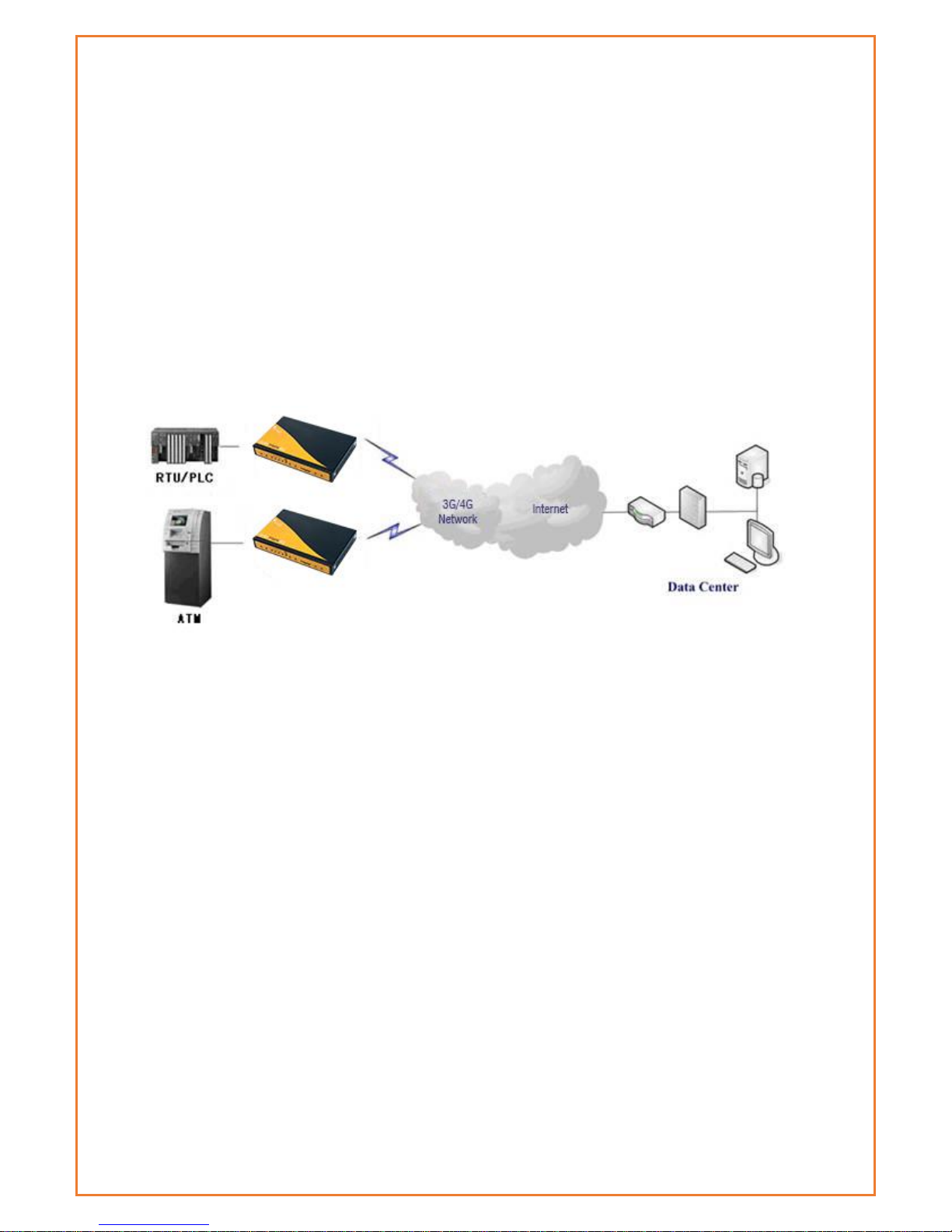
MA100-1010-4G is LTE Ethernet router providing data communications via the
public cellular network.
The MA100-1010-4G utilises an industrial 32-bit CPU with an embedded operating
system. The device supports RS232 connection, four Ethernet ports and Wi-Fi that
conveniently and transparently connect devices to a cellular network, allowing
you to connect to your existing serial and Ethernet devices with minimal
configuration.
The MA100-1010-4G has been widely used in M2M applications, such as intelligent
transportation, smart grid, industrial automation and telemetry.
Features and Benefits
Designed for Industrial Application
• Industrial cellular module MC7430
• High-powered industrial 32bit CPU
• Industrial GPS module
• Supports low power consumption mode, including sleep mode.
• Metal housing.
• Voltage range: 5~36VDC
• Auto recovery functionality, including online detection, and auto redial.
• Ethernet port: 1.5KV magnetic isolation protection
• RS232: 15KV ESD protection
• SIM port: 15KV ESD protection
• Power port 2.5mm Barrel connector: reverse-voltage and overvoltage
protection
• SMA antenna ports - gender varies for different radios
• IP Stack Auto mode
• IP / web based user interface for remote management, maintenance and
configuration.
Page 9
High-performance
• FDD-LTE CAT6 – Band 28 Supported
• Max.300 Mbps Download & Max. 50 Mbps Uplink
• 6 Band DC-HSPA+
• Supports multiple WAN access methods, including static IP, DHCP-
4GPPPOE, 3G/HSPA/4G.
• Supports GPS function
• Supports double link backup between Cellular and Wired WAN (PPPOE,
ADSL)
• Supports VPN client (PPTP, L2TP, OPENVPN, IPSEC and GRE)
• Supports VPN server (PPTP, L2TP, OPENVPN, IPSEC and GRE)
• Supports local and remote firmware upgrade, import and export config file.
• Supports Remote SMS
• Supports NTP, RTC embedded.
• Supports multiple DDNS provider services.
• Supports VLANs, MAC Address clone, PPPoE Server
• WIFI supports 802.11b/g/n and AP, client, Adhoc, Repeater, and Bridge
modes.
• WIFI security options include WEP, WPA, WPA2 encryption, Supports RADIUS
authentication and MAC address filter.
• Support DHCP server and client, firewall, NAT, DMZ host, URL block, QoS,
traffic, statistics, and real-time link speed statistics etc.
• Full protocol support, such as TCP/IP, UDP, ICMP, SMTP, HTTP, POP3, OICQ,
TELNET,), SNMP, , etc.
• Schedule Reboot, Schedule Online and Offline.
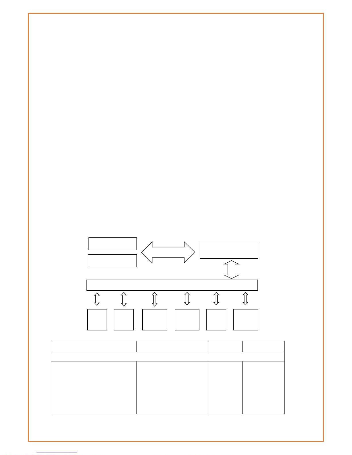
Router chart
Specifications
Cellular Specification
Standard and Band
Bandwidth
TX power
RX sensitivity
DATAMAX+ GPS+WCDMA WIFI ROUTER
LTE FDD: 1(2100MHz),
3(1800MHz), 5(850MHz),
7(2600MHz), 8(900MHz),
18(800MHz), 19(800MHz),
21(1500MHz), 28(700MHz)
LTE FDD: Download speed
Max. 300Mbps, Upload
speed Max. 50Mbps
<23dBm
<-97 dBm
Embedded processing
system
Cellular Module
Power
RS232
Indicator
lights
DATA
User interface
4 ports
switch
WIFI
AP
10/100M
WAN
GPS Module
Page 10

UMTS: 1(2100MHz), 5(850MHz),
6(850MHz), 8(900MHz),
9(1700MHz), 19(800MHz)
DC-HSPA+: Download
speed Max. 42Mbps,
Upload speed Max.
5.76Mbps
HSPA+: Download speed
Max. 21Mbps, Upload
speed Max. 5.76Mbps
HSDPA: Download speed
Max. 7.2Mbps, HSUPA,
Upload speed Max.
5.76Mbps
GPS Specification
Item
Content
GPS Module
Industrial GPS module
Receiver Type
50-channle
GPS L1(1575.42MHz)C/A code
SBAS: WAAS, EGNOS, MSAS, GAGAN
Support GALILEO
Max. update
rate
4 Hz
Accuracy
Position: 2.5m CPE
SBAS: 2.0m CPE
Acquisition
Cold starts: 29S
Warm starts: 29S
Aided starts: <1S
Hot starts: <1S
Sensitivity
Tracking: -160dBm
Reacquisition: -160dBm
Cold starts: -144dBm
Timing accuracy
RMS: 30ns
99%: <60ns
Granularity: 21ns
Time pulse
Configurable, 0.25 to 1000Hz
WIFI Specification
Item
Content
Page 11

Standard
IEEE802.11b/g/n
Bandwidth
IEEE802.11b/g: 54Mbps (max)
IEEE802.11n: 150Mbps (max)
Security
WEP, WPA, WPA2, etc.
WPS (optional)
TX power
20dBm(11n),24dBm(11g),26dBm(11b)
RX sensitivity
<-72dBm@54Mpbs
Hardware System
Item
Content
CPU
Industrial 32bits CPU
FLASH
16MB (Extendable to 64MB)
SDRAM
128MB
Interface Type
Item
Content
WAN
1x 10/100 Mbps WAN port(RJ45), auto MDI/MDIX, 1.5KV magnetic
isolation protection
LAN
4x 10/100 Mbps Ethernet ports(RJ45), auto MDI/MDIX, 1.5KV
magnetic isolation protection
Serial
1x RS232 port, 15KV ESD protection
Data bits: 5, 6 ,7, 8
Stop bits: 1, 1.5(optional), 2
Parity: none, even, odd, space(optional), mark(optional)
Baud rate: 2400~115200 bps
Indicator
"Power", "System", "Online", "GPS", " Local Network ", "WAN",
"WIFI", "Signal Strength"
Antenna
Cellular: Standard SMA female interface, 50 ohms
WIFI: Standard SMA male interface, 50 ohms
GPS: standard SMA female interfaces
SIM/UIM
Standard 3V/1.8V user card interface, 15KV ESD protection
Power
Standard 3-PIN power jack, reverse-voltage and overvoltage
protection
Reset
Restore the router to its original factory default settings
Page 12

Power Input
Item
Content
Standard Power
DC 12V/1.5A
Power Range
DC 5~36V
Consumption
Standby 292~342mA @12VDC
Communication 355~592mA @12VDC
Schedule Shutdown 2.57 ~4.2mA @12 VDC
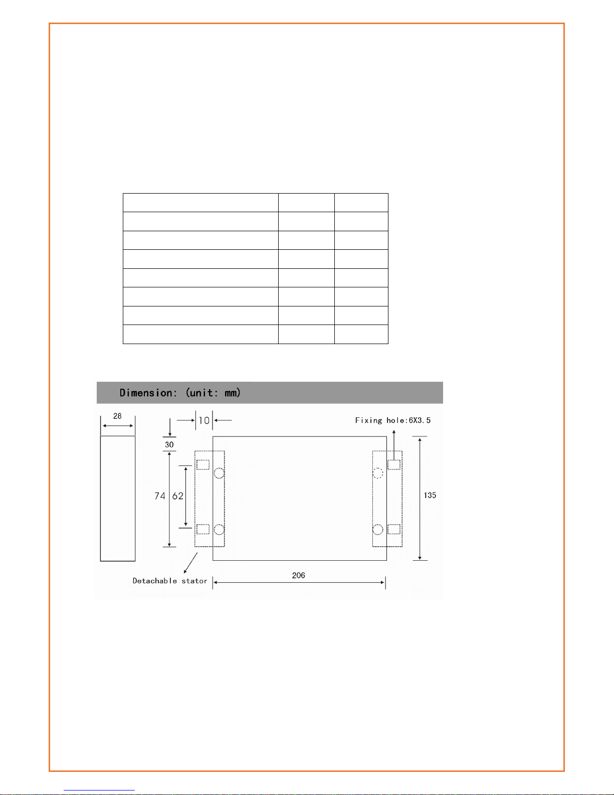
Physical Characteristics
Item
Content
Housing
Iron, providing IP30 protection
Dimensions
207x135x28 mm
Weight
790g
Environmental Limits
Item
Content
Operating
Temperature
-35~+75ºC(-31~+167℉)
Storage
Temperature
-40~+85ºC(-40~+185℉)
Operating
Humidity
95% (Non-condensing)
Page 13
Installation Introduction
Important
You should check the router configuration immediately after installation to ensure all
settings are as desired. Failure to do so may result in unauthorized access to your equipment.
Package Contents
Name
Quantity
Remark
Router
1
Cellular antenna (Male SMA)
1 WIFI antenna (Female SMA)
1
GPS antenna (Male SMA)
1 Ethernet cable
1
Console cable
1
optional
Power lead
1
Installation and Cable Connection
SIM card Installation
Power off the router, and press the eject button next to the SIM card tray with a
small tool such as a ballpoint pen. The SIM card tray will eject from inside of the
modem. Place the SIM card into the SIM card tray (ensure the SIM card is
properly put into the tray), and then insert the SIM card tray back into the SIM
card outlet.
Page 14

Antenna Installation
Attach the cellular antenna (with SMA male connector) into the female SMA
interface on the router labelled “ANT”.
Attach the WIFI antenna (with SMA female connector) into the male SMA
interface on the router labelled “WIFI”.
RS232 Interface
The router supports an RS232 interface that utilises an RJ45 connector and is
labelled as “Console” on the router.
If required, plug the RJ45 end of the serial cable into the RS232 port on the router
and plug the DB9F end of the serial cable into the serial interface of the user’s
device.
The pin connections of the RJ45-DB9F serial cable are as follows:
RJ45
DB9F
1
8
2
6
3 2 4 1 5 5 6 3 7 4 8
7
The signal definition of the DB9F serial communication interface is as follows:
Pin
RS232 signal
Direction
1
DCD
Output
2
RXD
Output
3
TXD
Input
4
DTR
Input
5
GND
6
DSR
output
Page 15

Power
The input supply voltage range is 5~36VDC. We recommend using the standard
DC 12VDC/1.5A power adaptor available from RFI.
7
RTS
input
8
CTS
output
Page 16

Indicator Lights Introduction
The router provides following indicator lights: “Power”, “System”, “Online”, “GPS”,
“Local Network”, “WAN”, “WIFI”, “Signal Strength”.
The table below shows the details of the LED functions:
Indicator Light
State
Introduction
Power
ON
Router is powered on
OFF
Router is powered off
System
BLINK
Router is up and working
OFF
Router is not currently working
Online
ON
Router has logged on network
OFF
Router hasn’t logged on network
GPS
ON
GPS is active
OFF
GPS is not active
Local Network
OFF
The corresponding interface of switch is not
connected
ON /
BLINK
The corresponding interface of switch is connected
/Communicating
WAN
OFF
The WAN interface is unplugged
ON /
BLINK
The WAN interface is plugged in/data is traversing
the WAN interface
WIFI
OFF
WIFI is not active
ON
WIFI is active
Signal Strength
One Light
ON
Signal strength is weak
Two
Lights ON
Signal strength is medium
Three
Lights ON
Signal strength is good
Reset Button
The modems “Reset” button is used to restore the modem to its original factory
default settings. To restore the router to factory default settings, the user needs to
press the “Reset” button and hold it in for 15s, the router will then restore its original
factory default settings and restart automatically. Note that the reset button is
recessed to prevent accidental resets – to press, use a small tool such as a
ballpoint pen.
Page 17
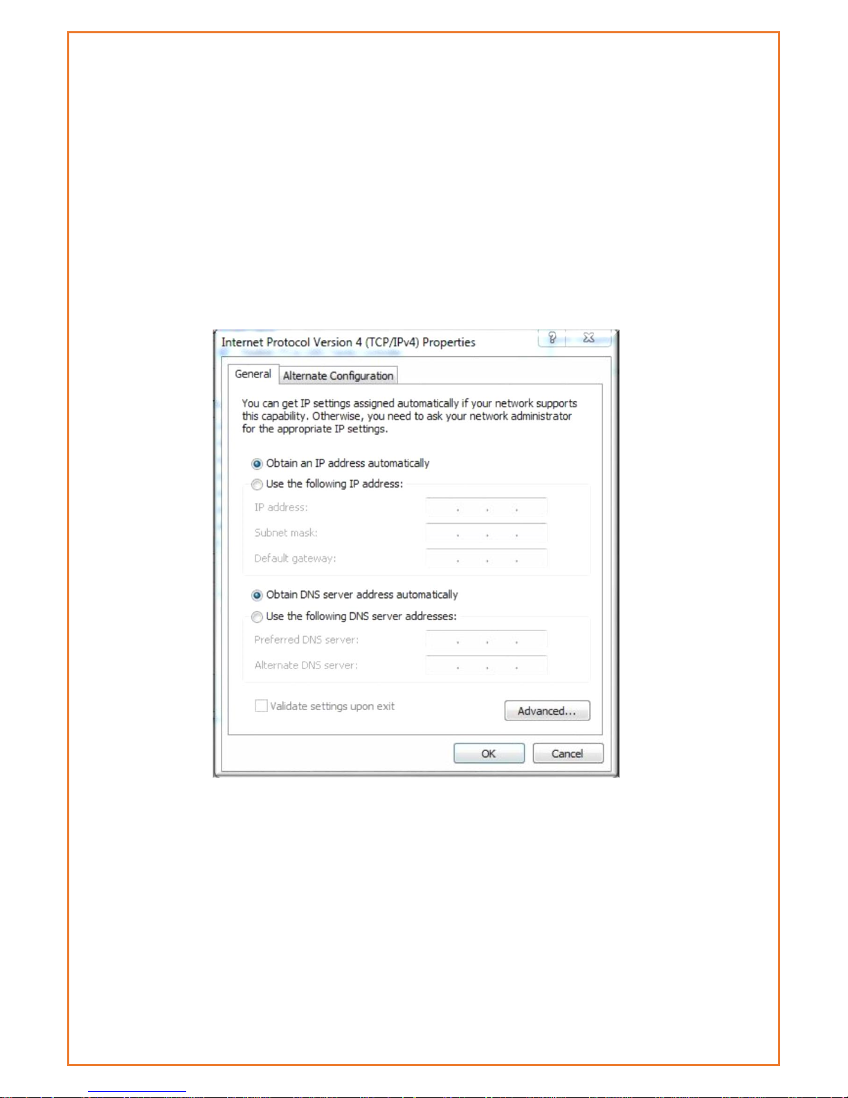
Configuration and Management
Datamax 4G is configured via a web interface. To access the Datamax 4G web
interface users will need a computer with a spare Ethernet LAN port. The LAN card
configuration should have the Internet Protocol TCP/IP set to obtain an IP Address
and DNS server address automatically.
To check these settings, users need to go to LAN adaptor properties and check
their Internet Protocol TCP/IP settings, it should look as follows:
Page 18
Connection Steps:
1. Connect the Ethernet cable supplied with Datamax router to your
computer Ethernet LAN port and a “LAN” port on the Datamax
2. Computer will get an IP address from the Datamax DHCP range
automatically.
3. In web browser type 192.168.0.1 in the Address (URL) field (The Default IP
Address of the Ethernet port is 192.168.0.1). The router will prompt to
change the login credentials, the default username and password are
both “admin”.
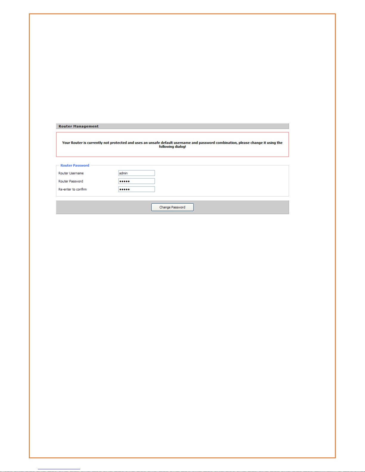
4. After providing the correct credentials, users access to the
information main page. It is strongly recommended that users at least
change the access password to avoid security risk.
Status
Router Information
This page shows basic information of Router including serial application and Memory.
System
Page 19
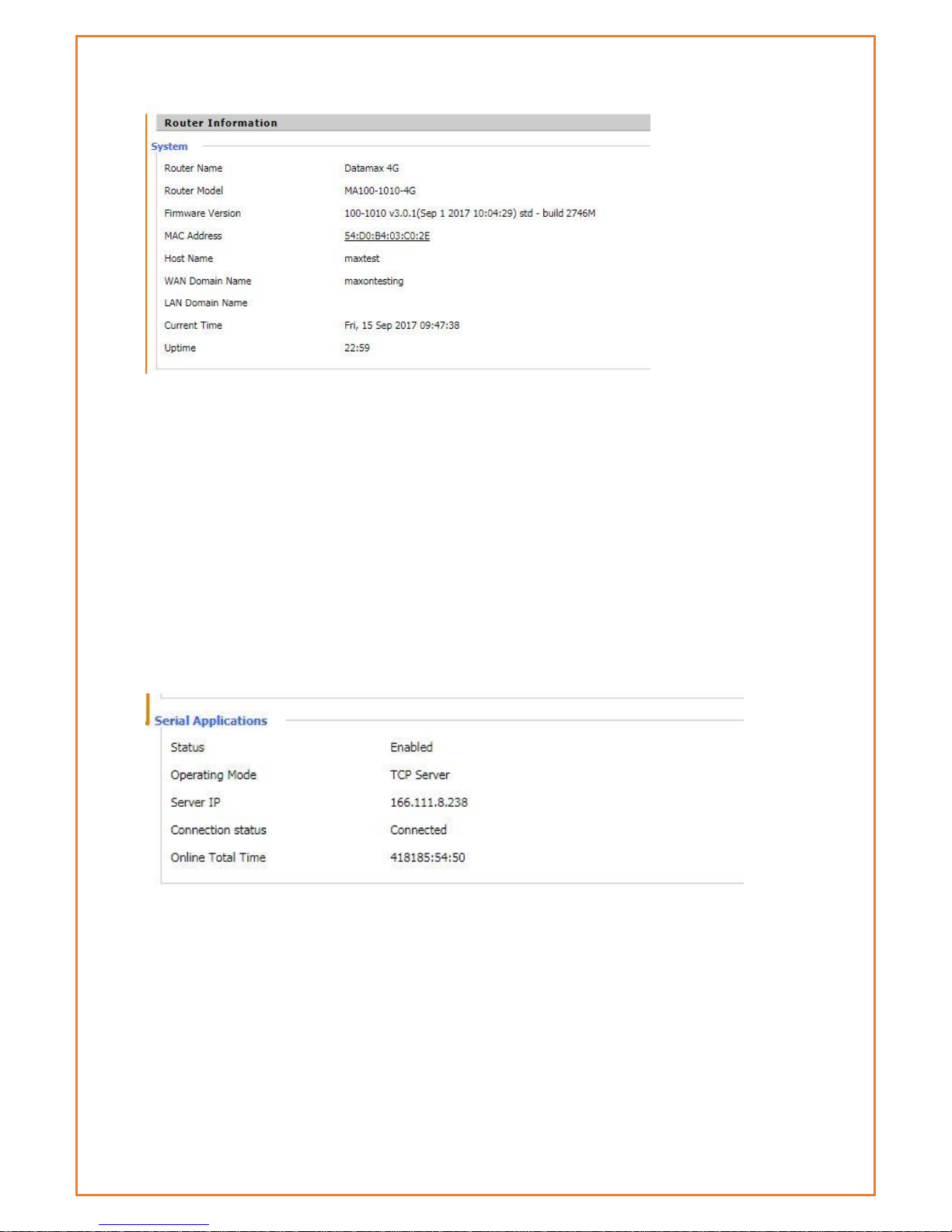
Router Name: This is the name of the router
Router Model: The model of the router
Firmware Version: This is the firmware version of board not module firmware
MAC Address: This is MAC address of Router
Host Name: This is host name of router
WAN Domain Name : This is WAN domain name of router
Current Time: This is current AEST time
Uptime: The uptime of router
Serial Application
Status: Status of serial port.
Operating Mode: Operating mode of router
Memory Status
Page 20
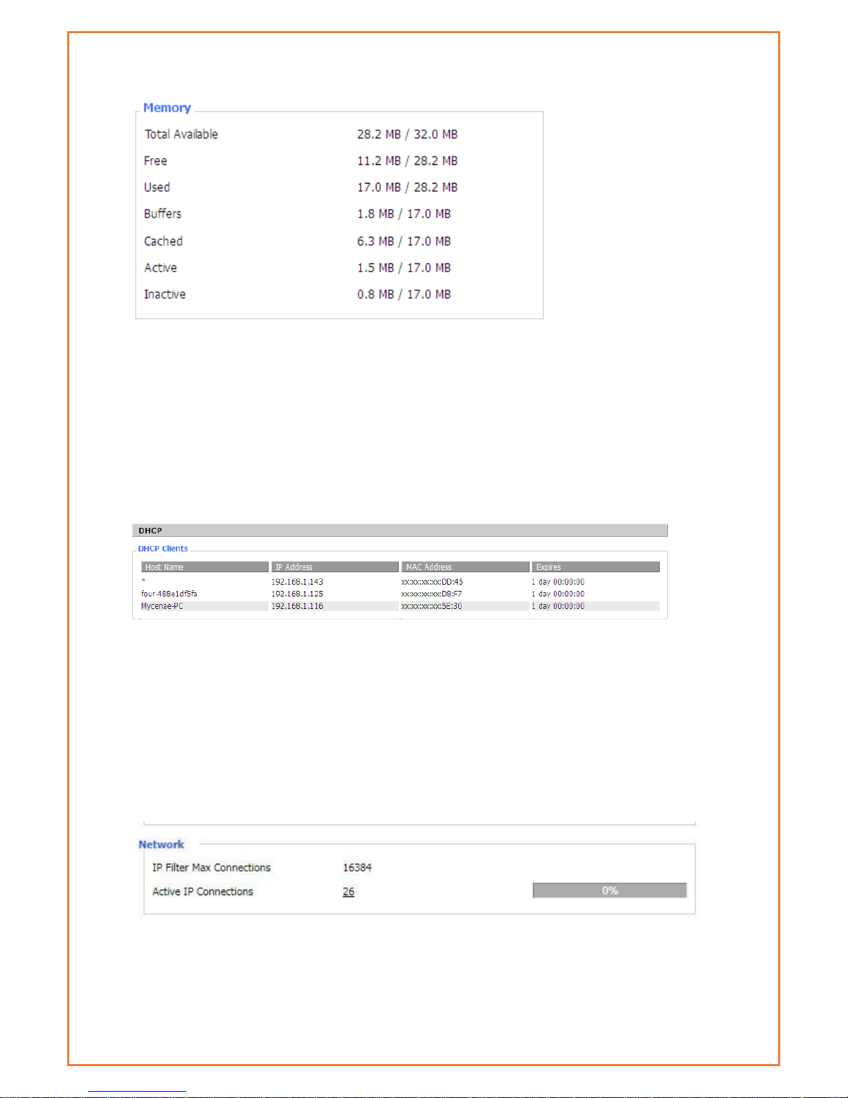
Total Available: The rooms for total available of RAM (that is physical memory minus some
reserve and the kernel of binary code bytes)
Free: free memory, the router will reboot if the memory is less than 500kB
Used: Used memory, total available memory minus free memory
Buffers: used memory for buffers, total available memory minus allocated memory
Cached: the memory used by high-speed cache memory
Active: Active use of buffer or cache memory page file size
Inactive: Not often used in a buffer or cache memory page file size
Host Name: Host name of LAN client
IP Address: IP address of the client
MAC Address: MAC address of the client
Expires: The expiry of the clients the IP address lease
Router Network information
This tab shows network information of router. This includes IP filter Max connection and Active IP
connection
LAN
Page 21
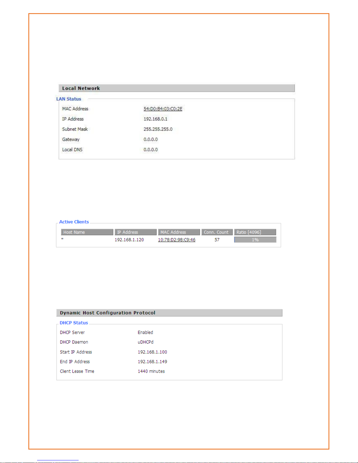
This page shows router internal network details. The details include MAC Address, IP address,
Subnet Mask, Gateway and local DNS. The page displays active LAN clients, status of DHCP and
details of DHCP client connected to LAN Interface. The Connected PPTP and L2TP clients and
server details are also listed in this page.
MAC Address: MAC Address of the LAN port Ethernet
IP Address: IP Address of the LAN port
Subnet Mask: Subnet Mask of the LAN port
Gateway: Gateway of the LAN port
Local DNS: DNS of the LAN port
Host Name: host name of LAN client
IP Address: IP address of the client
MAC Address: MAC address of the client
Conn. Count: count of connections from the client
Ratio: the ratio of 4096 connection
DNCP Server: Enable or disable the router work as a DHCP server
DHCP Daemon: The DHCP server process - DNSMasq or uDHCPd
Starting IP Address: The starting IP Address of the DHCP server’s Address pool
Page 22
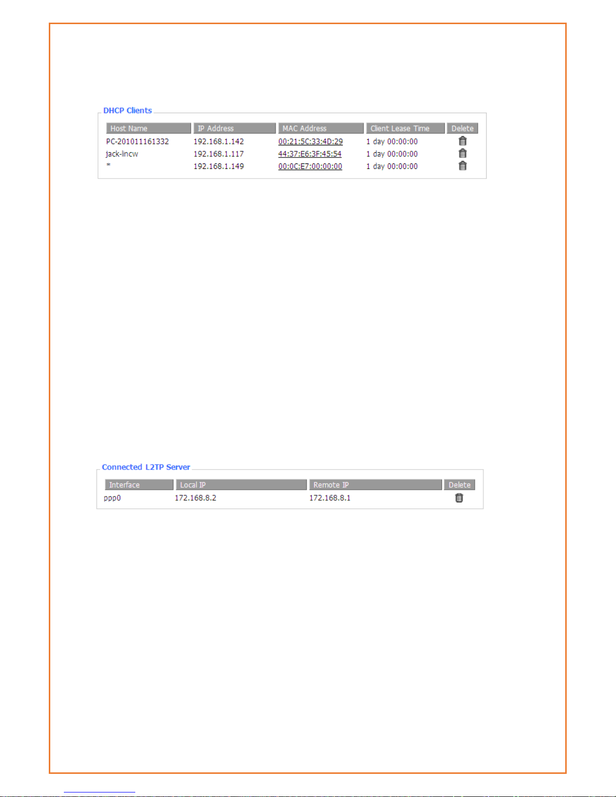
Ending IP Address: The ending IP Address of the DHCP server’s Address pool
Client Lease Time: The lease time of DHCP client
Host Name: Host name of LAN client
IP Address: IP address of the client
MAC Address: MAC address of the client
Expires: The expiry the client rents the IP address
Delete: Click to delete DHCP client
Connected L2TP server
This tab will only be displayed if L2TP Server is configured under Advanced feature>L2TP VPN.
This will provide connected L2TP Server.
Interface: The interface assigned by dial-up system
Local IP: Tunnel IP address of local L2TP
Remote IP: Tunnel IP address of remote L2TP client
Delete: click to disconnect L2TP
Connected L2TP clients
This tab will only be displayed if L2TP client is configured under Advanced feature>L2TP VPN. This
will provide connected L2TP clients.
Page 23
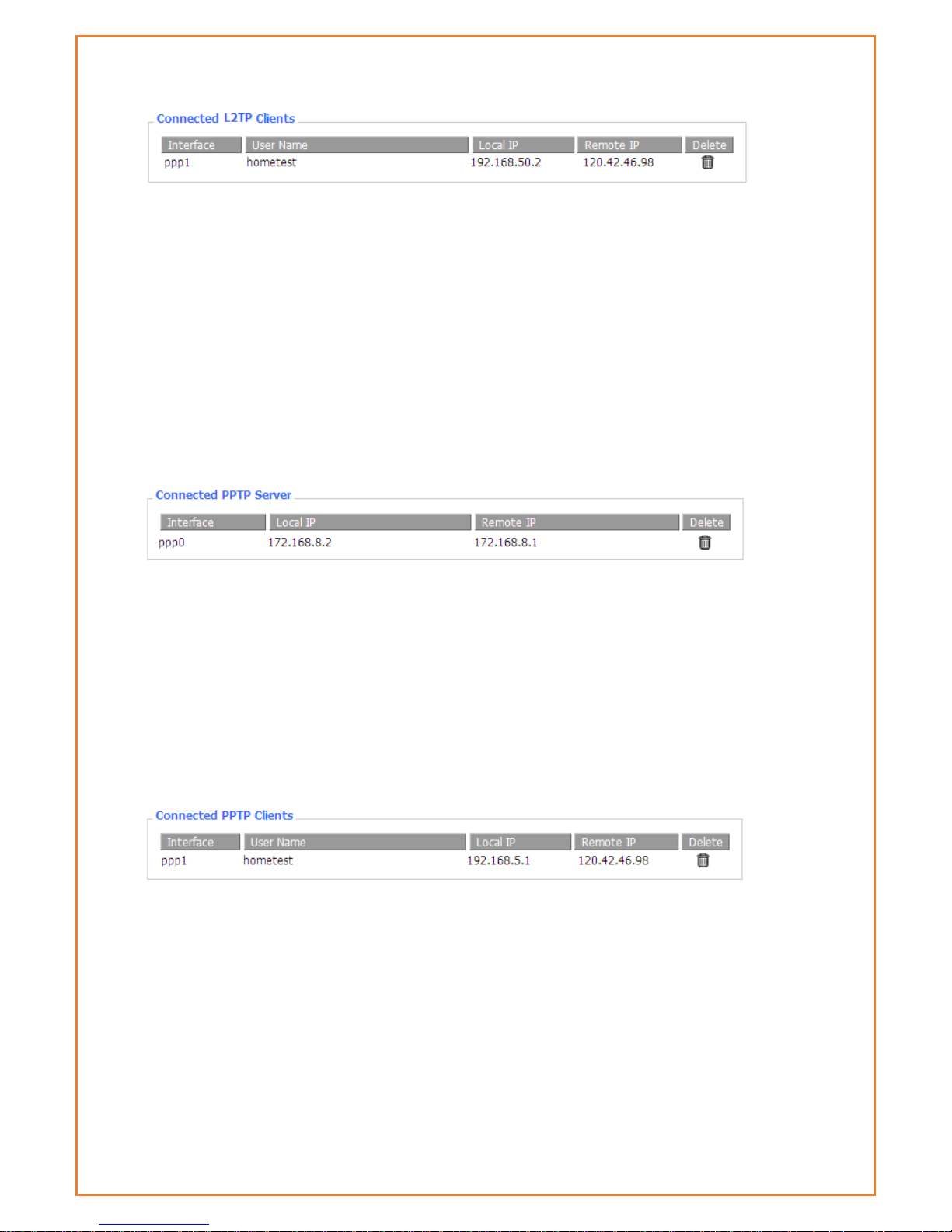
Interface: The interface assigned by dial-up system
User Name: User name of the client
Local IP: Tunnel IP address of the Datamax L2TP client
Remote IP: IP address of L2TP server the Datamax has connected to
Delete: Click to delete L2TP client
Connected PPTP Server
This tab will only be displayed if PPTP server is configured under Advanced feature>PPTP VPN.
This will provide connected PPTP Server.
Interface: The interface assigned by dial-up system
Local IP: Tunnel IP address of the local PPTP server (Datamax)
Remote IP: Tunnel IP address of remote PPTP client
Delete: Click to disconnect PPTP
Connected PPTP Server
This tab will only be displayed if PPTP clients is configured under Advanced feature>PPTP VPN.
This will provide connected PPTP clients.
Interface: The interface assigned by dial-up system
User Name: User name of the client
Local IP: Tunnel IP address of the local PPTP client (Datamax)
Remote IP: IP address of remote PPTP server
Delete: Click to delete PPTP client
Page 24
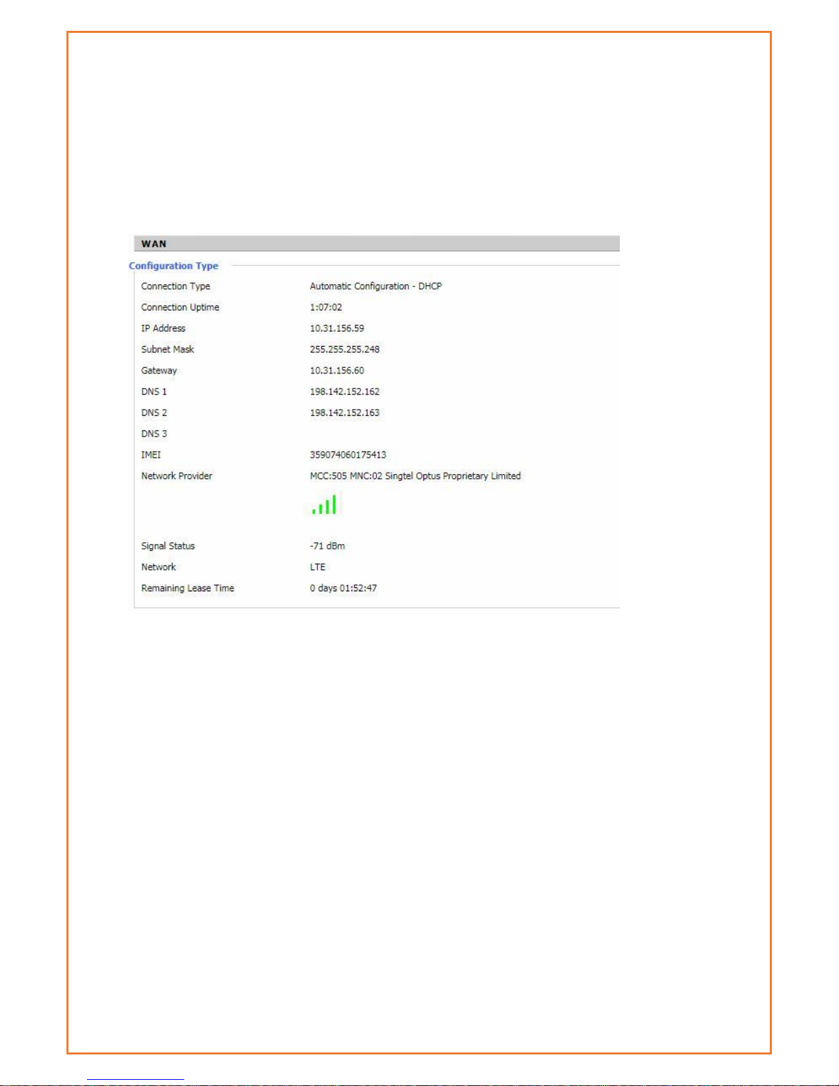
WAN
This page displays WAN connection information. Based on the WAN connection whether its 3G or
4G, it will display the details. The information includes connection type, WAN connection uptime,
IP address, subnet mask, gateway and DNS assigned by ISP. This page also displays the network
information like Network provider, signal strength, type of network and the lease details. The
IMEI number can be found in this page. The WAN traffic per month is displayed here and this can
be backup and restore later if required.
Connection Type: There are several connection types on Main WAN connection type. The
configured connection type will show under Connection type.
Connection Uptime: length of time this connection has been established ; If not connected,
displays “Not available”
IP Address: IP address of Datamax WAN connection
Subnet Mask: subnet mask of router WAN
Gateway: the default gateway of this WAN connection
DNS1, DNS2, DNS3: DNS1/DNS2/DNS3 of router WAN
Module Type: module type in 3G/UMTS way
Signal Status: signal strength reported by the module
Network: network type of the module in 3G/UMTS way
Remaining Lease Time: remaining lease time for the IP address of the WAN connection
DHCP Release: release DHCP address
DHCP Renew: renew IP address in DHCP way, default is 1 day
Page 25
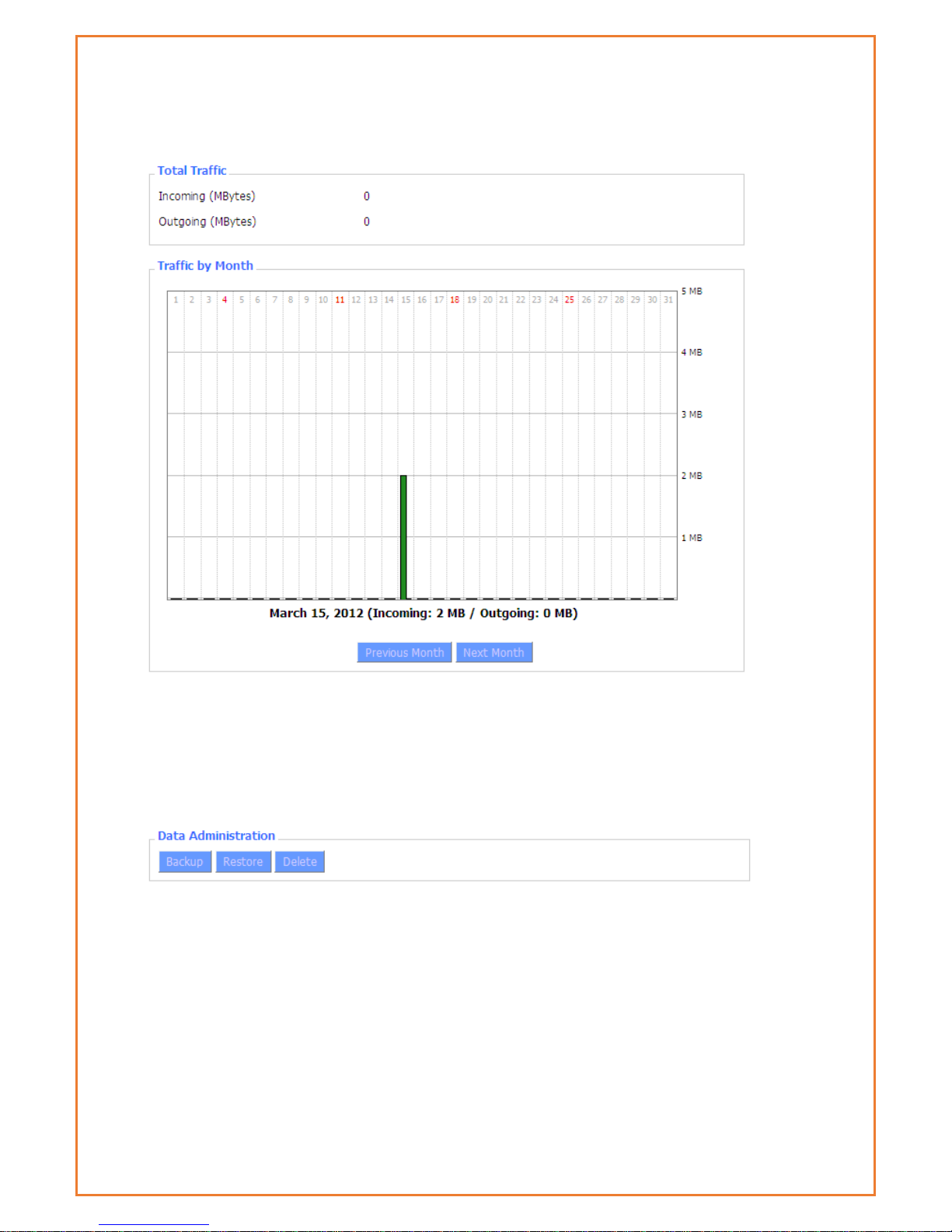
Total Traffic: flow from power-off last time until now statistics, download and upload direction
Traffic by Month: bar graph of the selected month data traffic
Previous Month: change graph to previous (ie, earlier) month
Next Month: change graph to next (ie, later) month
Backup: save traffic information to a file on your PC
Restore: restore traffic information from a file on your PC
Delete: delete traffic information from the Datamax
Page 26
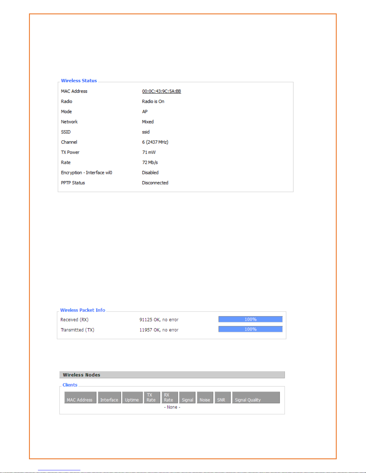
Wi-Fi
This page allows users to retrieve information of Wi-fi connection. Based on the Wi-Fi setup,
information is displayed in this page.
MAC Address: MAC address of wireless client
Radio: Display whether WiFi is enabled
Mode: Wireless mode – Access Point, Client etc
Network: Wireless network mode
SSID: Wireless network name
Channel: Wireless network channel
TX Power: Reflection power of wireless network
Rate: Reflection rate of wireless network
Encryption-Interface wl0: Enable or disable Encryption-Interface wl0
PPTP Status: WiFi connection status
Received (RX): Received data packet
Transmitted (TX): Transmitted data packet
MAC Address: MAC address of wireless client
Page 27
Interface: WiFi interface name of wireless client
Uptime: Connecting uptime of wireless client
TX Rate: Transmit rate of wireless client
RX Rate: Receive rate of wireless client
Signal: The signal of wireless client
Noise: The noise of wireless client
SNR: The signal to noise ratio of wireless client
Signal Quality: Signal quality of wireless client
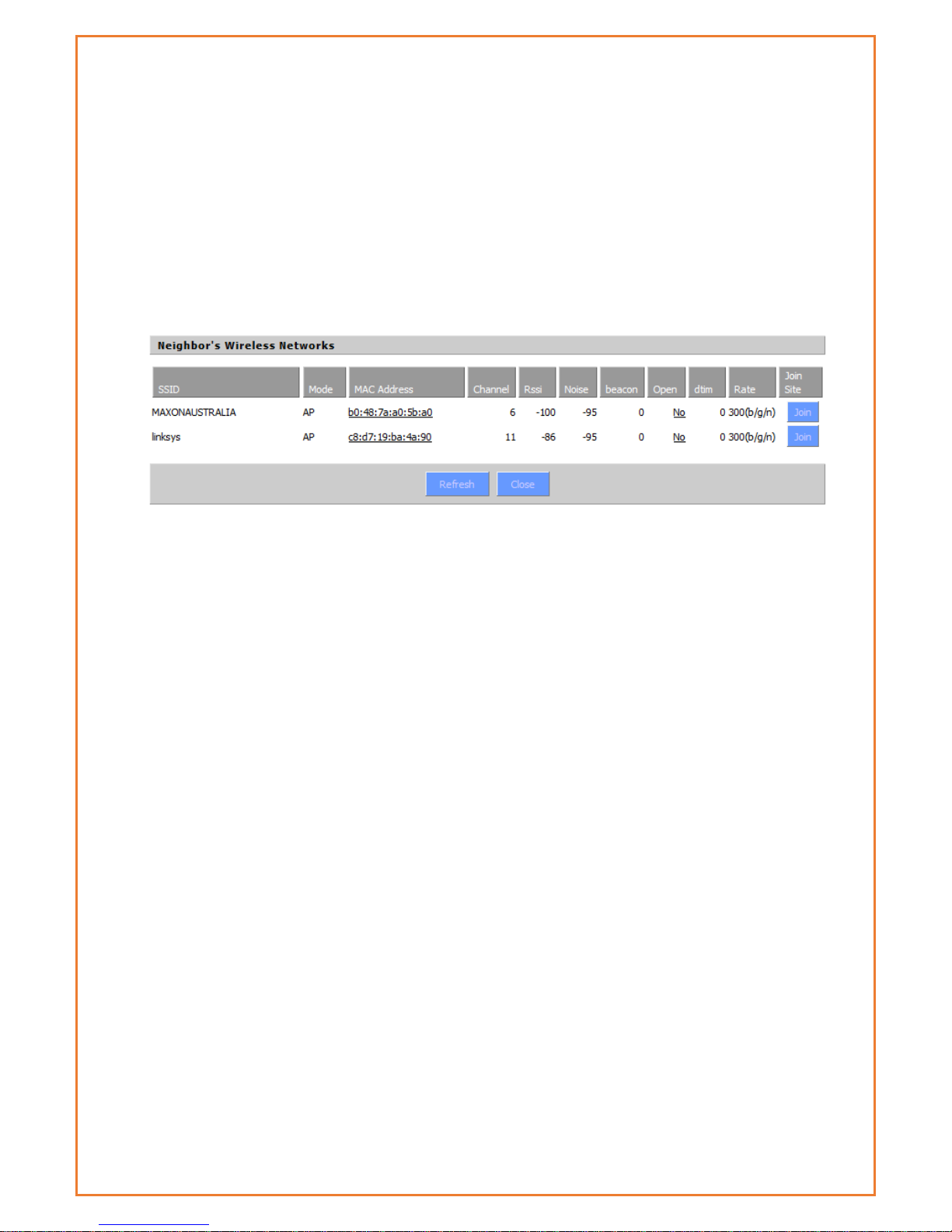
Neighbour’s Wireless Network: Display other networks nearby
SSID: The name of wireless network nearby
Mode: Operating mode of wireless network nearby
MAC Address: MAC address of the wireless nearby
Channel: The channel of the wireless nearby
RSSI: Signal intensity of the wireless nearby
Noise: The noise of the wireless nearby
Beacon: Signal beacon of the wireless nearby
Open: The wireless nearby require authentication to gain access or not
Dtim: Delivery traffic indication message of the wireless nearby
Rate: Speed rate of the wireless nearby
Join Site: Click to join wireless network nearby
Page 28
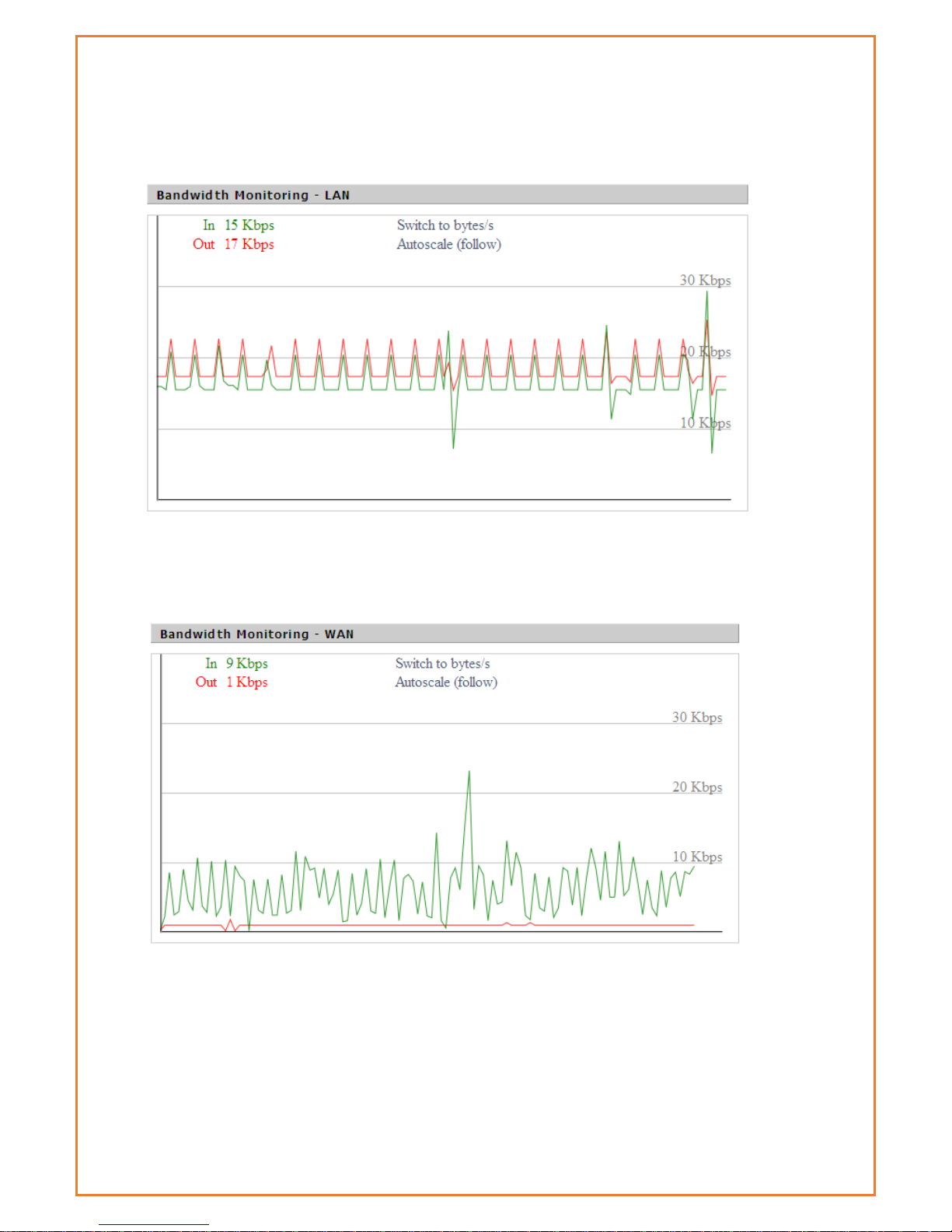
Bandwidth
This page display the bandwidth information on LAN and WAN.
Bandwidth Monitoring-LAN Graph
horizontal axis: Time
vertical axis: Speed rate
Bandwidth Monitoring-WAN Graph
horizontal axis: Time
vertical axis: Speed rate
Page 29
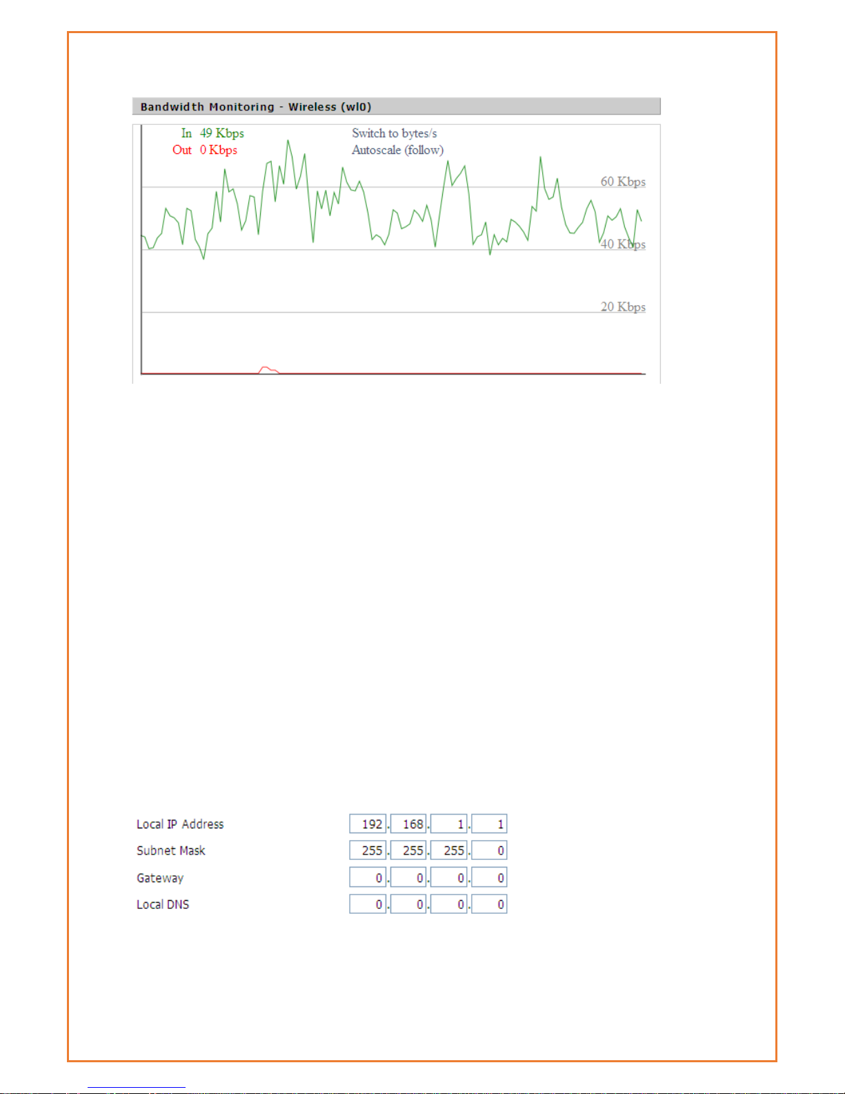
Bandwidth Monitoring-Wireless (W10) Graph
horizontal axis: Time
vertical axis: Speed rate
LAN & WAN Setup
LAN and WAN setup allow users to configure Local area network and Wide area network. When
LAN tab is clicked, users will be able to configure Local IP address, Subnet Mask, Gateway and
Local DNS along with DHCP settings and NTP client settings under LAN setup. For WAN Setup
users, can configure modem to connect to 4G or 3G network. Default is 4G connection. Router
can be configured for Automatic DHCP configuration if any device connects to WAN port. Dual
link option, WAN Nat and other optional settings can be configured.
LAN
This page allows users to configure router internal address, gateway, subnet mask and local DNS
as shown.
Router IP
Local IP Address: IP address of the routers LAN interface
Subnet Mask: The subnet mask of the routers LAN interface
Gateway: The default gateway address for LAN clients
Page 30

Local DNS: If you want to use nameservers attached to one of the Datamax LAN
ports, enter the IP address of the server here. To use the nameservers supplied by
the WAN interface, leave at 0.0.0.0
Page 31
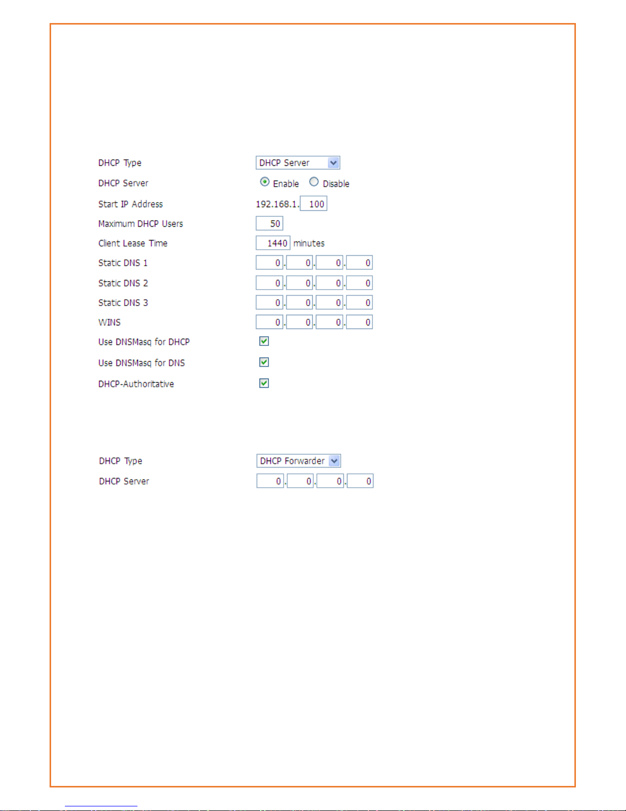
Network Address Server Settings (DHCP)
The Datamax 4G can act as a DHCP server for LAN connected devices. It can
also act as a DHCP forwarder where you are utilizing a central DHCP server for
multiple sites (subnets).
DHCP Type: select DHCP Server or DHCP Forwarder as appropriate
When you select DHCP Forwarder, you will see input fields for the IP address of the
remote DHCP server as below:
DHCP Server: Enable or disable the DHCP server
Start IP Address: The first (lowest) IP address to issue when a DHCP request comes
in – make sure you exclude the Datamax IP address!
Maximum DHCP Users: The maximum number of concurrent DHCP lease.
Client Lease Time: Leased time for IP address in minutes. After this amount of time,
the client will need to acquire a new lease if it wishes to remain connected.
Static DNS (1-3): If users wish to use their own DNS servers, users can enter their IP
addresses here. Leave blank to use WAN configured DNS servers.
WINS: if you are using a WINS server for name resolution, you can enter its IP
address here.
DNSMasq: Users' domain name in the field of local search, increase the expansion
of the host option, to adopt DNSMasq can assign IP addresses and DNS for the
subnet, if t DNSMasq is selected, dhcpd service is used for the subnet IP address
and DNS.
Page 32

Time Settings
Select time zone of your location. To use local time, leave the checkmark in the
box next to Use local time.
NTP Client: Enable this feature to get the system time from NTP server
Time Zone: Time zone options
Summer Time (DST): Set it depends on users' location
Server IP/Name: IP address of NTP server, up to 32 characters. If blank, the system
will find a server by default
Adjust Time
Where you are not using NTP, or the NTP server is currently unreachable, you can
set the routers real-time clock here. Click the “get” button to refresh the browser
page with the current router time and “Set” to set the current router time.
WAN
This WAN settings allow modem to connect to WAN network. Users can configure
modem to get WAN IP address using various option mention below. Some Internet
Service Providers (ISPs) will require users to enter specific information such as User
Name, Password, IP Address, Default Gateway Address, or DNS IP Address. This
information can be obtained from your ISP, if required. This page also has dual link
option, WAN NAT and optional settings for Wide Area network.
Page 33

DUAL LINK OPTION
This option is for redundancy purpose. When enabled, Backup Wan connection
tab will be displayed below the Main WAN connection and users can configure
backup link accordingly. “Dual Both online” can be enabled where modem will
be online for both main connection and backup connection all the time. Once
main connection fails, modem will automatically switch to backup link without
any further delay. “Dual Both Online” is also required for restoring the main WAN
interface when it is again available.
Main WAN Connection Type
There are seven configuration options for the WAN interface:
Disabled; Static IP; Automatic DHCP Configuration, dhcp-4G, PPOE, 3G Link 1, 3G
Link 2, dhcp-bkup4G
Disabled
The WAN port is not used
Static IP
WAN IP Address: IP address of the WAN interface
Subnet Mask: subnet mask of the WAN interface
Gateway: the default gateway address
Static DNS1/DNS2/DNS3: upstream DNS server IP addresses
Note that for use in your own internal network, your network administrator can
supply these details. Where you are using an ISP or other upstream service
provider, that supplier can supply you with the required details.
Automatic Configuration-DHCP
Page 34

IP address, netmask and default gateway of WAN port is all set automatically via DHCP. This is
useful when modem is connected to another router via its WAN Port.
DHCP-4G
This connection allows modem to connect to 4G network. Users are recommended to configure
with correct APN, username, password and authentication type provided by their ISP.
Page 35

PPPOE
User Name: Your username (typically supplied by your ISP)
Password: Your password (typically supplied by your ISP)
Service Name: If required by your ISP, otherwise leave blank.
PPP Compression (MPPC): If your ISP supports compression and you wish you use it,
it can be enabled here
T-Home VDSL VLAN 7/8 Tagging: If your ISP supports VDSL, you can enable it here.
MPPE Encryption: if your connection requires Microsoft point to point encryption,
shared key is entered here.
Single Line Multi Link: enable single line link or disable multi-link
Invalid PPP password characters’ list:
The password field doesn’t support the following characters.
“(double quotation mark)
‘(quotation mark)
?(question mark)
)(bracket)
@(at sign)
;(semi colon)
|(pipe sign)
I(upper case I)
3G Link 1
The WAN connection will be 2G/3G/4G on the Datamax 4G.
Page 36

User Name: your username (if any) as supplied by your mobile service provider
Password: your password (if any) as supplied by your mobile service provider
Dial String: the number to dial to get a data connection as supplied by your
mobile service provider
APN: access point name as supplied by your mobile service provider
SIM PIN
PIN: If sim is enable with PIN, users you can enter the PIN here
Connection type
Connection type: Auto, Force 4G, Force 3G, Force 2G, Prefer 3G, Prefer 2G
options. In most cases Auto is preferred, however in some circumstances and
locations, you can gain reliability and/or speed advantages by forcing
connection options.
Keep Online
This function is used to monitor your WAN connectivity so that “broken”
connections can be re-established, or alternate connections established.
Detection Method:
None: do not monitor connectivity.
Ping: Send ICMP Echo requests to the primary and backup detection server
address
Page 37

Route: Detect connection with route method, when choose this method, users
should also configure "Detection Interval", "Primary Detection Server IP"
and "Backup Detection Server IP" items.
PPP: Detect connection with PPP method, when choose this method, users
should also configure "Detection Interval" item.
Detection Interval: time (in seconds) to wait between detection attempts.
Primary Detection Server IP: the primary (first) server that should be reachable and
respond to the configured detection method
Backup Detection Server IP: the backup (second) server that should be reachable
via the WAN interface and respond to the configured detection method
Note: Both the primary and backup detection servers should be stable and
reliable – if these servers fail to respond correctly in a timely manner, the modem
will attempt to drop and re-establish the connection. During this time, no
incoming or outgoing traffic can be send/received
Note: The main and backup WAN detection servers have the route to their IP
address bound to the specified link (main or backup). Therefore, main and
backup link detection servers are required to be different. This also means that the
detection servers should not also perform another required function – that is, you
should not assign the same IPs as used for link detection to DNS server(s), or to be
the target of serial port or GPS data etc.
Fixed WAN IP, Fixed WAN Gateway can be configured using the following settings.
Enabling this feature allocate modem with fix WAN IP with fix WAN Gateway. Dial
failure to restart (default 10 mins) feature along with Ppp Asyncmap can also be
enabled. Enabling dial failure to restart enable modem to run the dial up script
every 10 minutes.
Note: for “dual both on-line” (a main and backup WAN), you should disable
“Enable Dial Failure to Restart” or the modem will reboot on extended main
WAN link failure
Force reconnect
Enabling this option forces the Datamax 4G to drop the WAN connection and
then re-establish it at the defined interval.
Page 38

Time: the time between forced reconnects.
STP
STP (Spanning Tree Protocol) allows for multiple redundant links while preventing
routing loops – packets do not “ping-pong” from router to router.
Page 39

Optional Configuration
Router Name: set router name
Host Name: the host name part of the FQDN of the Datamax
Domain Name: the domain part of the FQDN of the Datamax
MTU: Maximum (user) data size in packets sent. Usually “auto”, however
depending on your ISP and/or local network settings, you may need to reduce
this – please contact your network administrator and/or ISP.
Services
DHCP Server
DHCP assigns IP addresses to user’s local devices. While the main configuration is on the setup
page users can program some nifty special functions here.
Use NVRAM for client lease DB: The DHCP server will attempt to assign the same IP address to
the client at each lease request, based on the clients MAC address. Setting this option saves
MAC/IP assignments between reboots of the router.
Page 40

Used domain: users can select here which domain the DHCP clients should get as their local
domain. This can be the WAN domain set on the Setup screen or the LAN domain which can be
set here.
LAN Domain: users can define here their local LAN domain which is used as local domain for
DNSmasq and DHCP service if chose above.
Static Leases: if users want to assign certain hosts a specific address then they can define them
here. This is also the way to add hosts with a fixed address to the router's local DNS service
(DNSmasq).
Additional DHCPd Options: some extra options users can set by entering them
Page 41

DNSMasq
DNSmasq is a local DNS server. It will resolve all host names known to the router from dhcp
(dynamic and static) as well as forwarding and caching DNS entries from remote DNS servers.
Local DNS enables DHCP clients on the LAN to resolve static and dynamic DHCP hostnames.
Note: when using main and backup WAN, you should disable DNSMasq
Local DNS: enables DHCP clients on the LAN to resolve static and dynamic DHCP hostnames
No DNS Rebind: when enabled, it can prevent an external attacker to access the router's internal
Web interface. It is a security measure
Additional DNSMasq Options: some extra options users can set by entering them in Additional
DNS Options.
For example:
static allocation: Dhcp-host=AB:CD: EF: 11:22:33,192.168.0.10,myhost,myhost.domain,12h
max lease number: Dhcp-lease-max=2
DHCP server IP range: Dhcp-range=192.168.0.110,192.168.0.111,12h
SNMP
Location: Equipment location
Contact: Contact this equipment management
Name: Device name
RO Community: SNMP RO community name, the default is public, Only to read.
RW Community: SNMP RW community name, the default is private, Read-write permissions
Page 42
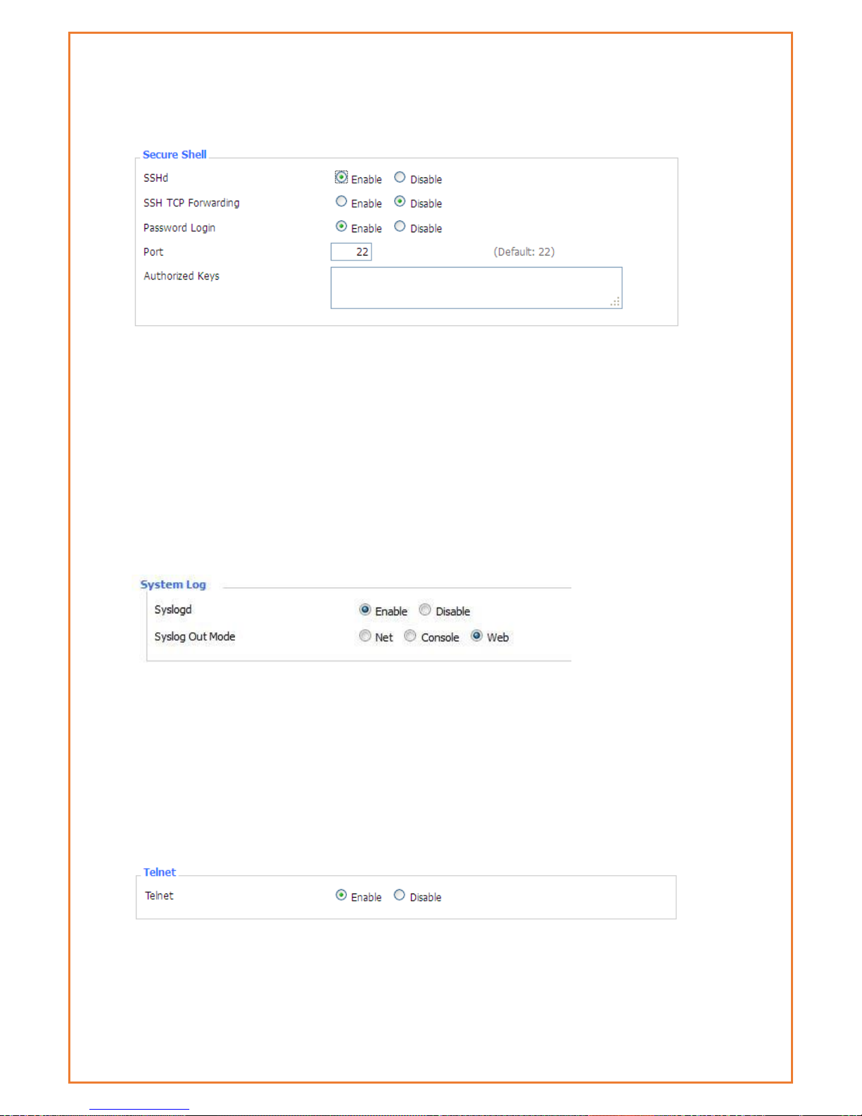
SSHD
Enabling SSHd allows users to access the Linux OS of their router with an SSH client
SSH TCP Forwarding: enable or disable to support the TCP forwarding (SSH tunnels)
Password Login: allows login with the router password (username is admin)
Port: port number for SSHd (default is 22)
Authorized Keys: here users paste their public keys to enable key-based login (more secure than
a simple password)
System log
Enable Syslogd to capture system messages. By default, they will be collected in the local file
/var/log/messages. To send them to another system, enter the IP address of a remote syslog
server.
Syslog Out Mode: three logging modes:
Net: the log information output to a syslog server
Console: the log information output to console port
Web: the log information is available via the router webpage under “Administration” menu
Remote Server: if choose net mode, users should input a syslog server’s IP Address
Telnet
Telnet: enable a telnet server to connect to the router with telnet. The username is admin and
the password is the router's password.
Page 43

Note: If users use the router in an untrusted environment (for example as a public hotspot), it is
strongly recommended to use SSHd and deactivate telnet, as the router login information is send
without encryption in the telnet protocol.
WAN Traffic Counter
Ttraff Daemon: enable or disable wan traffic counter function
Wi-Fi
Wireless Network
“Enable” or “Disable” the Wi-Fi of the router.
Wireless Mode
AP, Client, Adhoc, Repeater, Repeater Bridge.
Wireless Network Mode:
Mixed
Support 802.11b, 802.11g, 802.11n wireless devices.
Page 44

BG-Mixed
Support 802.11b, 802.11g wireless devices.
B-only
Only supports the 802.11b standard wireless devices.
G-only
Only supports the 802.11g standard wireless devices.
NG-Mixed
Support 802.11g, 802.11n wireless devices.
N-only
Only supports the 802.11g standard wireless devices.
Greenfield
If no other Wi-Fi coverage is in the area, this mode will increase throughput.
However, when this mode is used where other Wi-Fi is present, throughput will
decrease.
Mixed
When other Wi-Fi coverage is in the area, this mode reduces errors. However,
when used where no other Wi-Fi is available, this decreases throughput.
Wireless Network Name(SSID)
The SSID is the network name shared among all devices in a wireless network. The
SSID must be identical for all devices in the wireless network. It is case-sensitive and
must not exceed 32 alphanumeric characters, which may be any keyboard
character. Make sure this setting is the same for all devices in your wireless
network.
Wireless Channel
A total of 1-13 channels to choose more than one wireless device environment,
please try to avoid using the same channel with other devices.
Channel Width
20MHZ and 40MHZ。
Wireless SSID Broadcast:
Enable
SSID is announced and advertised by the router
Disable
SSID is not advertised – you cannot “browse” this network to connect, you
must know it exists.
Network Configuration:
Page 45
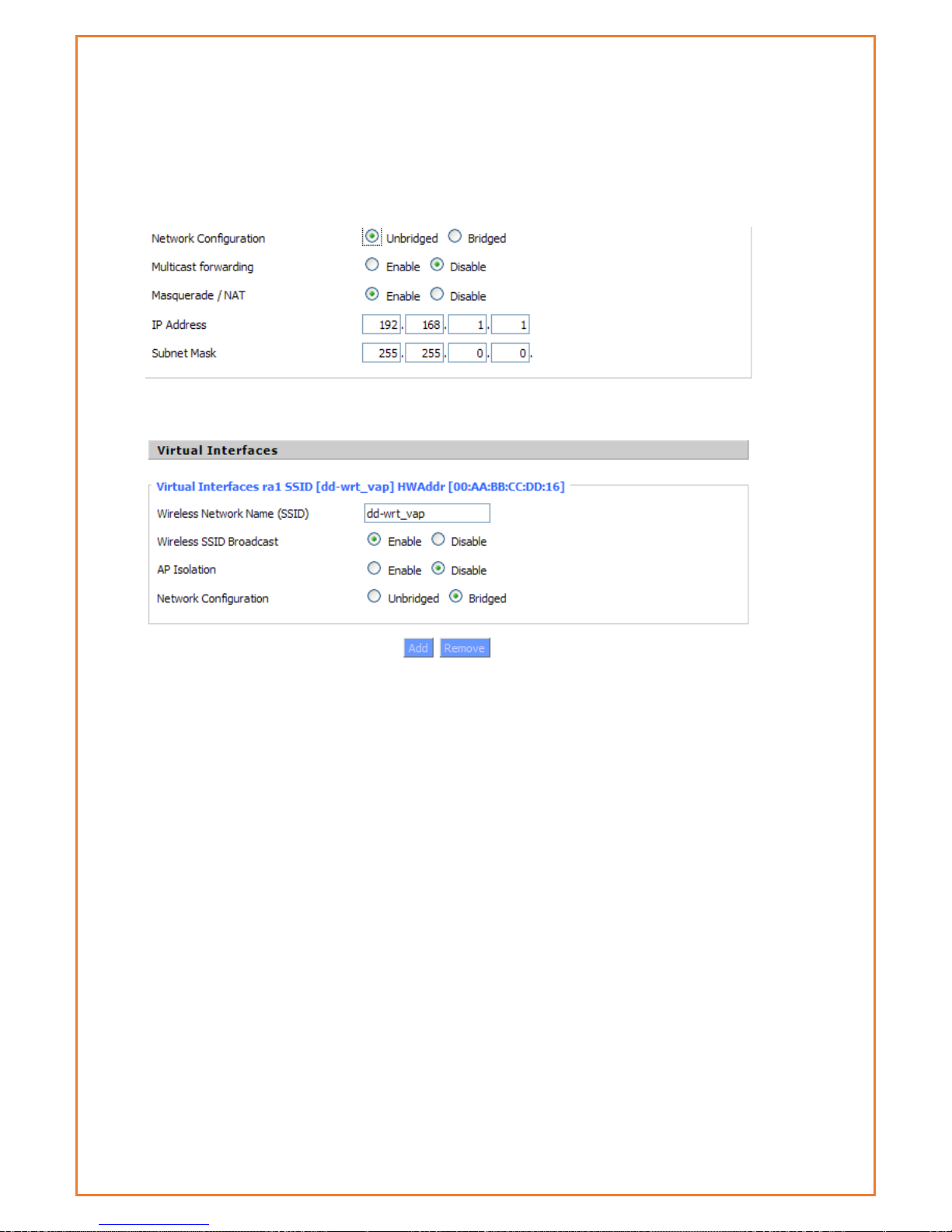
Bridged:Bridge to the router, under normal circumstances, please select the
bridge. In this mode, WiFi clients and LAN clients appear as one network
segment.
Unbridged There is no bridge to the router, IP addresses need to manually
configure.
Virtual Interfaces:Click Add to add a virtual interface. Add successfully, click on
the remove, you can remove the virtual interface。
AP Isolation
This setting isolate wireless clients so that client-to-client access between different
SSIDs is prohibited.
Note: Save the changes, after changing the "Wireless Mode", "Wireless Network
Mode", "wireless width", "broadband" option, please click on this button, and then
configure the other options.
Wi-Fi Security
Wireless security options used to configure the security of your wireless network.
This route is a total of seven kinds of wireless security mode. Disabled by default,
not safe mode is enabled. Such as changes in Safe Mode, click Apply to take
effect immediately.
Page 46
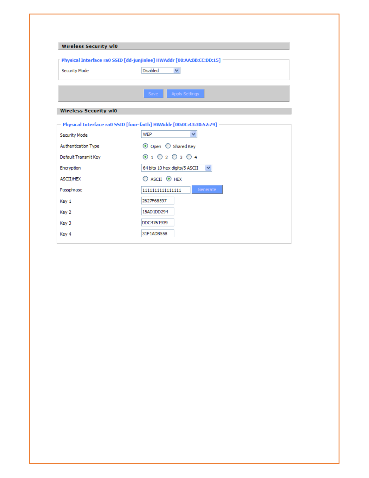
WEP:
This Is a basic encryption algorithm that is less secure than WPA. Use of WEP is
discouraged due to security weaknesses, and one of the WPA modes should be
used whenever possible. Only use WEP if you have clients that can only support
WEP (usually older, 802.11b-only clients).
Authentication Type
Open or shared key
Default Transmit Key
Select the key form Key 1 - Key 4 key.
Encryption
There are two levels of WEP encryption, 64-bit (40-bit) and 128-bit. To utilize WEP,
select the desired encryption bit, and enter a passphrase or up to four WEP key in
hexadecimal format. If you are using 64-bit (40-bit), then each key must consist of
exactly 10 hexadecimal characters or 5 ASCII characters. For 128-bit, each key
must consist of exactly 26 hexadecimal characters. Valid hexadecimal characters
are "0"-"9" and "A"-"F".
ASCII/HEX: ASCII, the keys is 5 bit ASCII characters/13bit ASCII characters.
HEX, the keys is 10bit/26 bit hex digits.
Passphrase:The letters and numbers used to generate a key.
Page 47
Key1-Key4:Manually fill out or generated according to input the pass phrase.
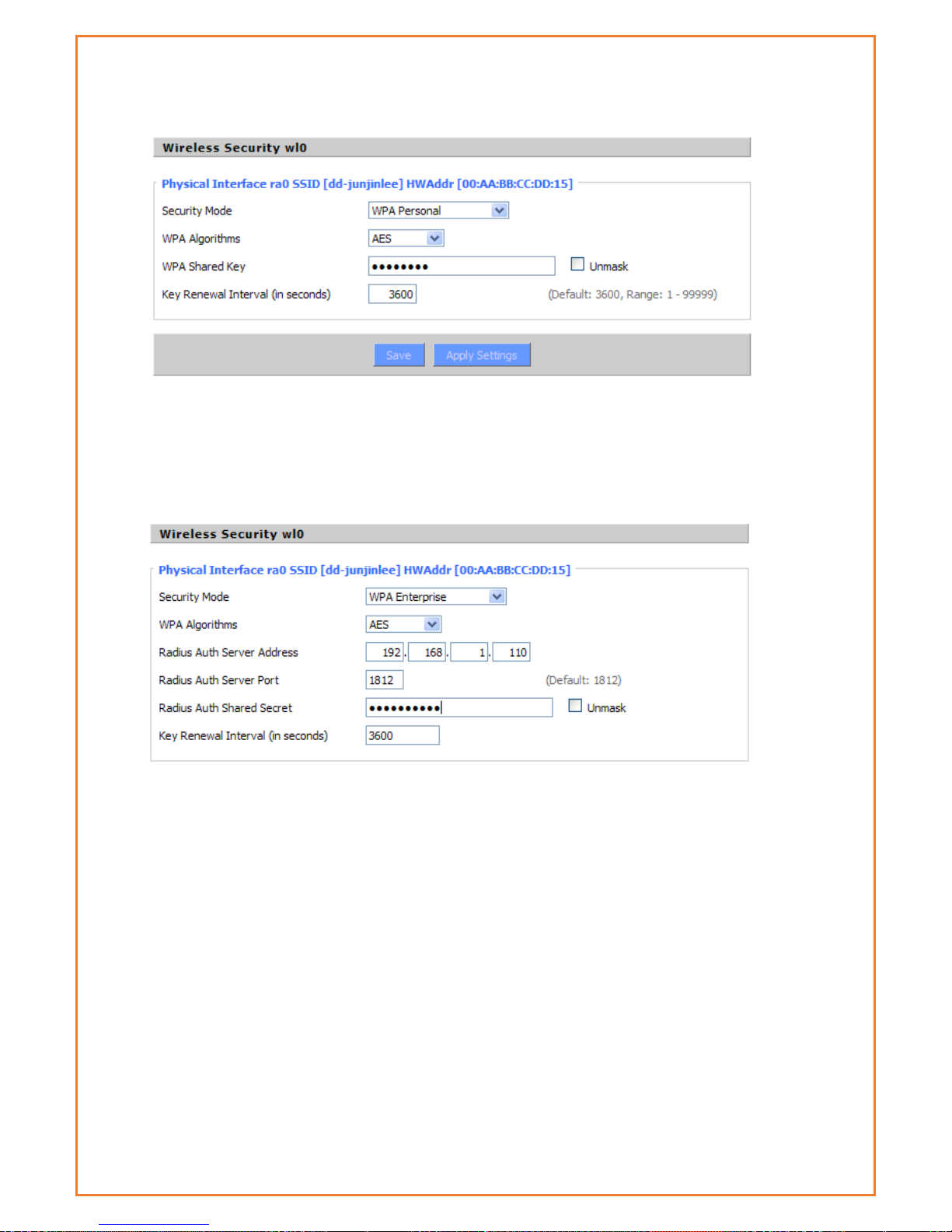
WPA Personal/WPA2 Personal/WPA2 Person Mixed
TKIP/AES/TKIP+AES,dynamic encryption keys. TKIP + AES, self-applicable TKIP or
AES. WPA Person Mixed, allows WPA Personal and WPA2 Personal client mix.
WPA Shared Key:Between 8 and 63 ASCII character or hexadecimal digits. 。
Key Renewal Interval in seconds):1-99999。
WPA Enterprise/WPA2 Enterprise/WPA2 Enterprise Mixed: WPA Enterprise uses an
external RADIUS server to perform user authentication.
WPA Algorithms
AES/TKIP/TPIP+AES.
Radius AUTH Sever Address
The IP address of the RADIUS server.
Radius AUTH Server Port
The RADIUS Port (default is 1812)
Radius AUTH Shared Secret
The shared secret from the RADIUS server。
Key Renewal Interval (in seconds): 1-99999。
Page 48

Advanced Feature
DDNS
For users that have a dynamically assigned IP address, a DNS server that supports
dynamic DNS updates will allow you to refer to your devices by name and have
them continue to connect correctly even when the IP address of the device
changes. The Datamax 4G router supports dynamic DNS updates, automatically
updating the DNS server when the WAN interface IP address assignment changes.
DDNS Service: The Maxon MA100-1010-4G router currently supports DynDNS,
freedns, Zone edit, NO-IP, 3322, easyDNS, TZO, DynSIP and Custom based on the
user.
User Name: DDNS server username
Password: DDNS server password
Host Name: FQDN of the DDNS server
Type: Select the appropriate value (list varies depending on the setting of “DDNS
Service”)
Wildcard: Support wildcard or not, the default is OFF. ON means *.host.3322.org is
equal to host.3322.org
Do not use external ip check: Enable or disable the function of 'do not use
external ip check'
Force Update Interval: How often (in days) to force a DDNS update, even if the IP
address hasn’t changed.
Page 49

DDNS Status shows DDNS specific log information
Page 50

PPTP VPN
This page allows users to configure PPTP server and PPTP client. Users can remotely access the
device behind the modem using this VPN.
PPTP Server
Users can configure modem as PPTP server with the following setting. For more details
information please contact Maxon Australia support team for application guides
Broadcast support: Enable or disable broadcast support of PPTP server
Force MPPE Encryption: Enable of disable force MPPE encryption of PPTP data
DNS1/DNS2/WINS1/WINS2: set DNS1/DNS2/WINS1/WINS2
Server IP: Input IP address of the router as PPTP server, differ from LAN address
Client IP(s): IP address assigns to the client, the format is xxx.xxx.xxx.xxx-xxx
CHAP Secrets: user name and password of the client using PPTP service
Note: client IP must be different with IP assigned by router DHCP.
The format of CHAP Secrets is user * password *.
Page 51

PPTP Client
Users can configure modem as PPTP client with the following setting. For more details
information please contact Maxon Australia support team for application guides
Server IP or DNS Name: PPTP server’s IP Address or DNS Name
Remote Subnet: the network of the remote PPTP server
Remote Subnet Mask: subnet mask of remote PPTP server
MPPE Encryption: enable or disable Microsoft Point-to-Point Encryption。
MTU: maximum Transmission Unit
MRU: maximum Receive Unit
NAT: network Address Translation
User Name: user name to login PPTP Server.
Password: password to log into PPTP Server.
Page 52

L2TP VPN
Force MPPE Encryption: enable or disable force MPPE encryption of L2TP data
Server IP: Input IP address of the router as PPTP server, differ from LAN address
Client IP(s): IP address assigns to the client, the format is xxx.xxx.xxx.xxx-xxx.xxx.xxx.xxx
CHAP Secrets: User name and password of the client using L2TP service
Note: client IP must be different with IP assigned by router DHCP.
The format of CHAP Secrets is user * password *.
Page 53

L2TP Client
Gateway (L2TP Server): L2TP server’s IP Address or DNS Name
Remote Subnet: The networks of remote L2TP server
Remote Subnet Mask: Subnet mask of remote L2TP server
MPPE Encryption: Enable or disable Microsoft Point-to-Point Encryption
MTU: Maximum transmission unit
MRU: Maximum receive unit
NAT: Network address translation
User Name: User name to login L2TP Server
Password: Password to login L2TP Server
Require CHAP: Enable or disable support chap authentication protocol
Refuse PAP: Enable or disable refuse to support the pap authentication
Require Authentication: Enable or disable support authentication protocol
Page 54

Open VPN
OPENVPN Server
Start Type: WAN UP----start after on-line, System----start when boot up
Config via: OpenVPN configuration using the GUI (web page) or a file
Server mode: Router (TUN)-route mode (layer 3 link), Bridge (TAP)----bridge mode (layer 2 link)
Router (TUN):
Network: network address allowed by OPENVPN server
Netmask: netmask allowed by OPENVPN server
Bridge (TAP):
DHCP-Proxy mode: enable or disable DHCP-Proxy mode
Pool start IP: pool start IP of the client allowed by OPENVPN server
Pool end IP: pool end IP of the client allowed by OPENVPN server
Gateway: the gateway of the client allowed by OPENVPN server
Netmask: netmask of the client allowed by OPENVPN server
Port: listen port of OPENVPN server
Tunnel Protocol: UCP or TCP of OPENVPN tunnel protocol
Note: for maximum security and speed, choose UDP
Encryption Cipher: Blowfish CBC,AES-128 CBC,AES-192 CBC,AES-256 CBC,AES-512 CBC
Page 55

Hash Algorithm: Hash algorithm provides a method of quick access to data, including SHA1,
SHA256,SHA512,MD5
Advanced Options
Use LZO Compression: enable or disable use LZO compression for data transfer
Redirect default Gateway: enable or disable redirect default gateway
Allow Client to Client: enable or disable allow client to client
Allow duplicate cn: enable or disable allow duplicate cn
TUN MTU Setting: set the value of TUN MTU
TCP MSS: MSS of TCP data
TLS Cipher: TLS (Transport Layer Security) encryption standard supports AES-128 SHA and AES256 SHA
Client connect script: define some client script by user self
CA Cert: CA certificate
Public Server Cert: server certificate
Private Server Key: the key set by the server
DH PEM: PEM of the server
Page 56

Additional Config: additional configurations of the server
CCD-Dir DEFAULT file: other file approaches
TLS Auth Key: authority key of Transport Layer Security
Certificate Revoke List: configure some revoke certificates
Page 57

OPENVPN Client
Server IP/Name: IP address or domain name of OPENVPN server
Port: listen port of OPENVPN client
Tunnel Device: TUN----Router mode, TAP----Bridge mode
Tunnel Protocol: UDP and TCP protocol
Encryption Cipher: Blowfish CBC,AES-128 CBC,AES-192 CBC,AES-256 CBC,AES-512 CBC
Hash Algorithm: Hash algorithm provides a method of quick access to data, including SHA1,
SHA256, SHA512, MD5
nsCertType verification: support ns certificate type
Use LZO Compression: enable or disable use LZO compression for data transfer
NAT: enable or disable NAT through function
Bridge TAP to br0: enable or disable bridge TAP to br0
Local IP Address: set IP address of local OPENVPN client
TUN MTU Setting: set MTU value of the tunnel
TCP MSS: mss of TCP data
Page 58
TLS Cipher: TLS (Transport Layer Security) encryption standard supports AES-128 SHA and AES-256
SHA
TLS AUTH Key: authority key of Transport Layer Security
Additional Config: additional configurations of OPENVPN server
Policy based Routing: input some defined routing policy
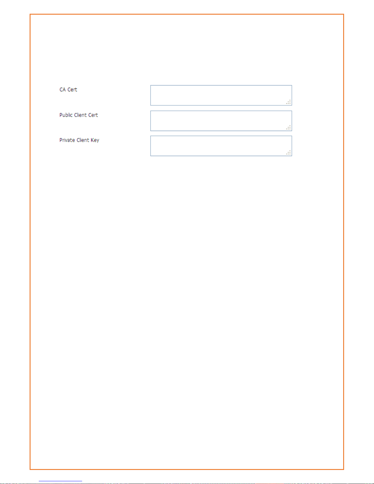
CA Cert: CA certificate
Public Client Cert: client certificate
Private Client Key: client key
Page 59

IPSEC
Connect Status and Control
Show IPSEC connection and status of current router on IPSEC page.
Name: the name of IPSEC connection
Type: The type and function of current IPSEC connection
Common name: local subnet, local address, opposite end address and opposite end subnet of
current connection
Status: connection status: closed, negotiating, establish
Closed: this connection does not launch a connection request to opposite end
Negotiating: this connection launches a request to opposite end, is under negotiating, the
connection has not been established yet
Establish: the connection has been established, enabled to use this tunnel
Action: the action of this connection, current is to delete, edit, reconnect and enable
Delete: to delete the connection, also will delete IPSEC if IPSEC has set up
Edit: to edit the configure information of this connection, reload this connection to make the
configuration effect after edit
Reconnect: this action will remove current tunnel, and re-launch tunnel establish request
Enable: when the connection is enable, it will launch tunnel establish request when the system
reboot or reconnect, otherwise the connection will not do it
Add: to add a new IPSEC connection
Add IPSEC connection or edit IPSEC connection
Type: to choose IPSEC mode:
Net-to-Net VPN: create a site-to-site tunnel
Host-to-Host VPN: create a client-to-site tunnel
Connection: this part contains basic address information of the tunnel
Page 60
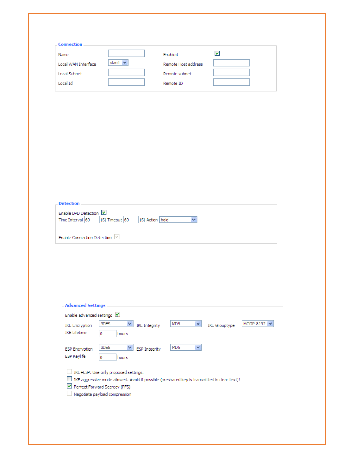
Name: to indicate this connection name, must be unique
Enabled: If enable, the connection will send tunnel connection request when it is reboot or re-
connection, otherwise it is no need if disable
Local WAN Interface: local address of the tunnel
Remote Host Address: IP/domain name of end opposite; this option disabled in server mode
Local Subnet: IPSec local protects subnet and subnet mask, i.e. 192.168.1.0/24
Remote Subnet: IPSec opposite end protects subnet and subnet mask, i.e.192.168.7.0/24
Local ID: tunnel local end identification, IP and domain name are available
Remote ID: tunnel opposite end identification, IP and domain name are available
Detection: this part contains configure information of connection detection
Enable DPD Detection: Enable or disable this function, tick means enable
Time Interval: Set time interval of connect detection (DPD)
Timeout: Set the timeout of connect detection
Action: set the action of connect detection
Advanced Settings: This part contains relevant setting of IKE, ESP, negotiation mode, etc.
Enable Advanced Settings: Enable to configure 1st and 2nd phase information, otherwise it
Page 61
will automate negotiation according to opposite end
IKE Encryption: IKE phased encryption mode
IKE Integrity: IKE phased integrity solution
IKE Group type: DH exchange algorithm
IKE Lifetime: set IKE lifetime, current unit is hour, the default is 0
ESP Encryption: ESP encryption type
ESP Integrity: ESP integrity solution
ESP Key life: Set ESP key life, current unit is hour, the default is 0
IKE aggressive mode allowed: Negotiation mode adopt aggressive mode if tick; it is main
mode if non-tick
Negotiate payload compression: Tick to enable PFS, non-tick to disable PFS
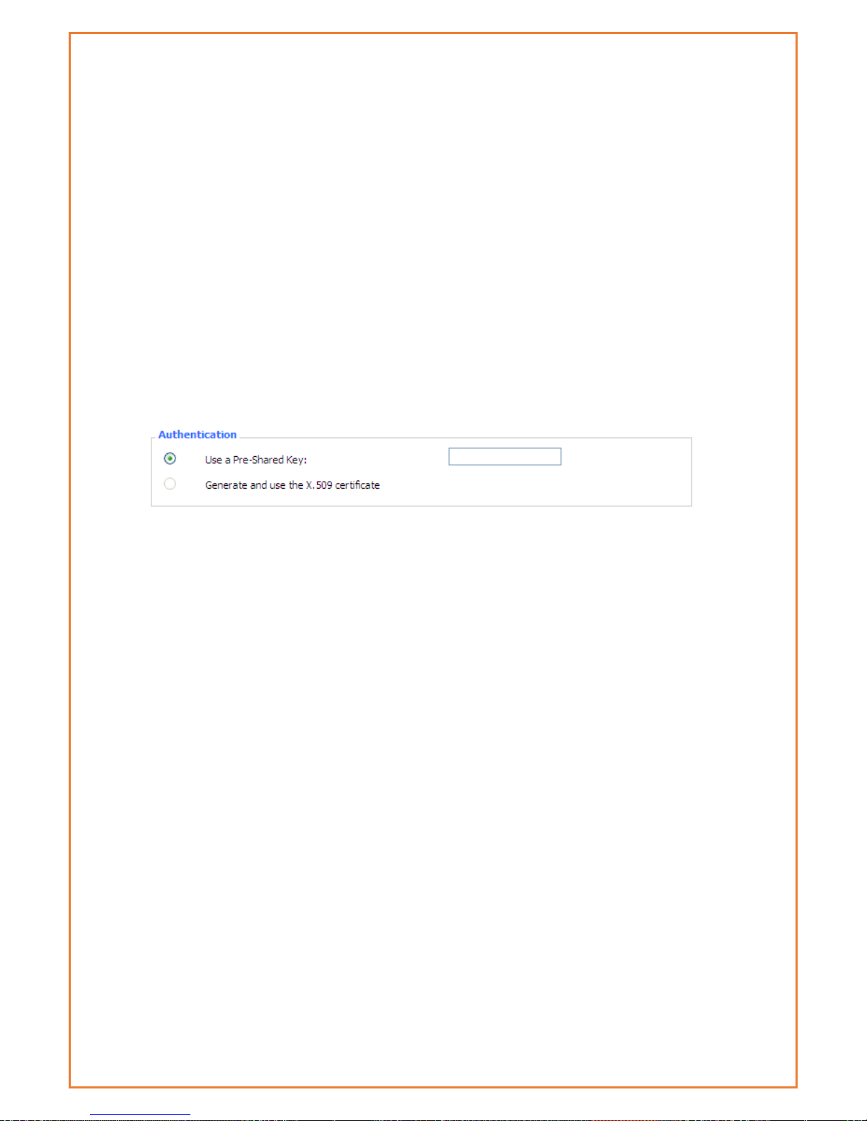
Authentication: choose use share encryption option or certificate authentication option. Current
is only to choose use share encryption option.
Page 62
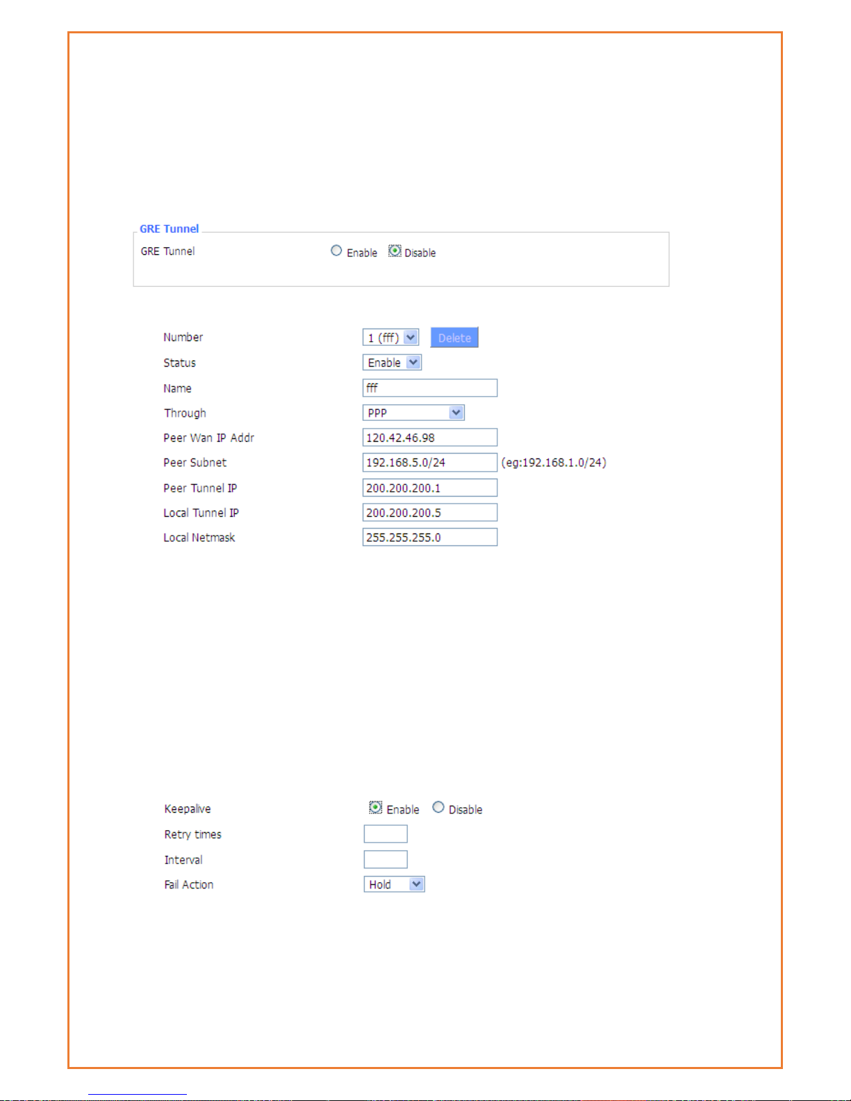
GRE
GRE (Generic Routing Encapsulation) protocol is a network layer protocol (such as IP and IPX)
data packets are encapsulated, so these encapsulated data packets to another network layer
protocol (IP)transmission. GRE Tunnel (tunnel) technology, Layer Two Tunnelling Protocol VPN
(Virtual Private Network).
GRE Tunnel: enable or disable GRE function
Number Switch on/off GRE tunnel app
Status Switch on/off someone GRE tunnel app
Name:GRE tunnel name
Through:The GRE packet transmit interface
Peer Wan IP Addr:The remote WAN address
Peer Subnet:The remote gateway local subnet, e.g.: 192.168.1.0/24
Peer Tunnel IP:The remote tunnel ip address
Local Tunnel IP:The local tunnel ip address
Local Netmask:Netmask of local network
Keepalive:Enable or disable GRE Keepalive function
Retry times:GRE keepalive detect fail retries
Interval:The time interval of GRE keepalive packet sent
Fail Action The action would be exec after keeping alive failed
Page 63
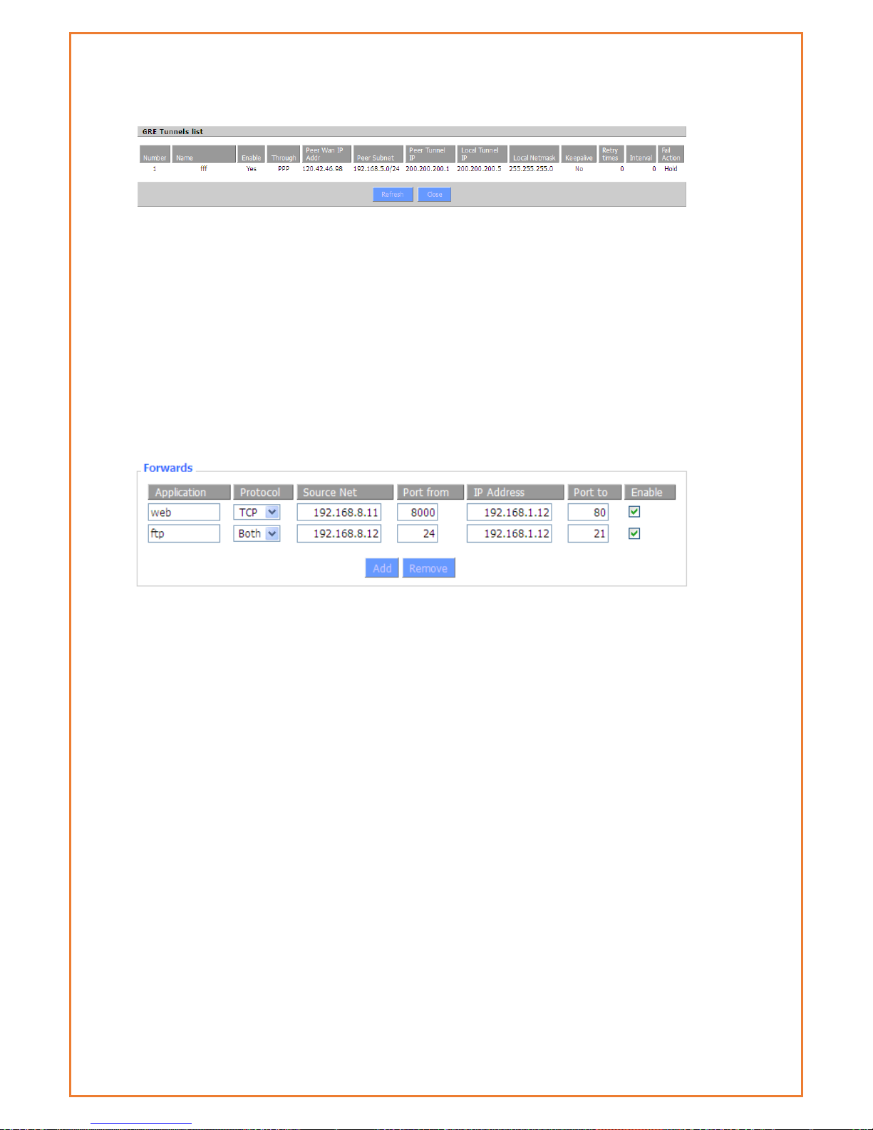
Click on “View GRE tunnels” keys can view the information of GRE
Port Forwarding
Port Forwarding allows you to set up public services on your network, such as web servers, ftp
servers, e-mail servers, or other specialized Internet applications.
Specialized Internet applications are any applications that use Internet access to perform
functions such as videoconferencing or online gaming. When users send this type of request to
your network via the Internet, the router will forward those requests to the appropriate PC.
Application: Enter the name of the application in the field provided.
Protocol: Chose the right protocol TCP, UDP or Both. Set this to what the application requires.
Source Net: Forward only if sender matches this ip/net (example 192.168.1.0/24).
Port from: Enter the number of the external port (the port number seen by users on the
Internet).
IP Address: Enter the IP Address of the PC running the application.
Port to: Enter the number of the internal port (the port number used by the application).
Enable: Click the Enable checkbox to enable port forwarding for the application.
Check all values and click Save Settings to save your settings. Click the Cancel changes
button to cancel your unsaved changes.
Port Range Forwarding
Port Range Forwarding allows you to set up public services on your network, such as web servers,
ftp servers, e-mail servers, or other specialized Internet applications. Specialized Internet
applications are any applications that use Internet access to perform functions such as
videoconferencing or online gaming. When users send this type of request to your network via
the Internet, the router will forward those requests to the appropriate PC.
Page 64

Application: Enter the name of the application in the field provided.
Start: Enter the number of the first port of the range you want to be seen by users on the
Internet and forwarded to your PC.
End: Enter the number of the last port of the range you want to be seen by users on the Internet
and forwarded to your PC.
Protocol: Chose the right protocol TCP, UDP or Both. Set this to what the application requires.
IP Address: Enter the IP Address of the PC running the application.
Enable: Click the Enable checkbox to enable port forwarding for the application.
Check all values and click Save Settings to save your settings. Click the Cancel changes
button to cancel your unsaved changes.
DMZ
The DMZ (Demilitarized Zone) hosting feature allows one local user to be exposed to the
Internet for use of a special-purpose service such as Internet gaming or videoconferencing. DMZ
hosting forwards all the ports at the same time to one PC. The Port Forwarding feature is more
secure because it only opens the ports you want to have opened, while DMZ hosting opens all the
ports of one computer, exposing the computer so the Internet can see it.
Any PC whose port is being forwarded should have a static IP address assigned to it because
its IP address may change when using the DHCP function.
DMZ Host IP Address: To expose one PC to the Internet, select Enable and enter the computer's
IP address in the DMZ Host IP Address field. To disable the DMZ, keep the default setting Disable
Check all values and click Save Settings to save your settings. Click the Cancel changes
button to cancel your unsaved changes.
Page 65
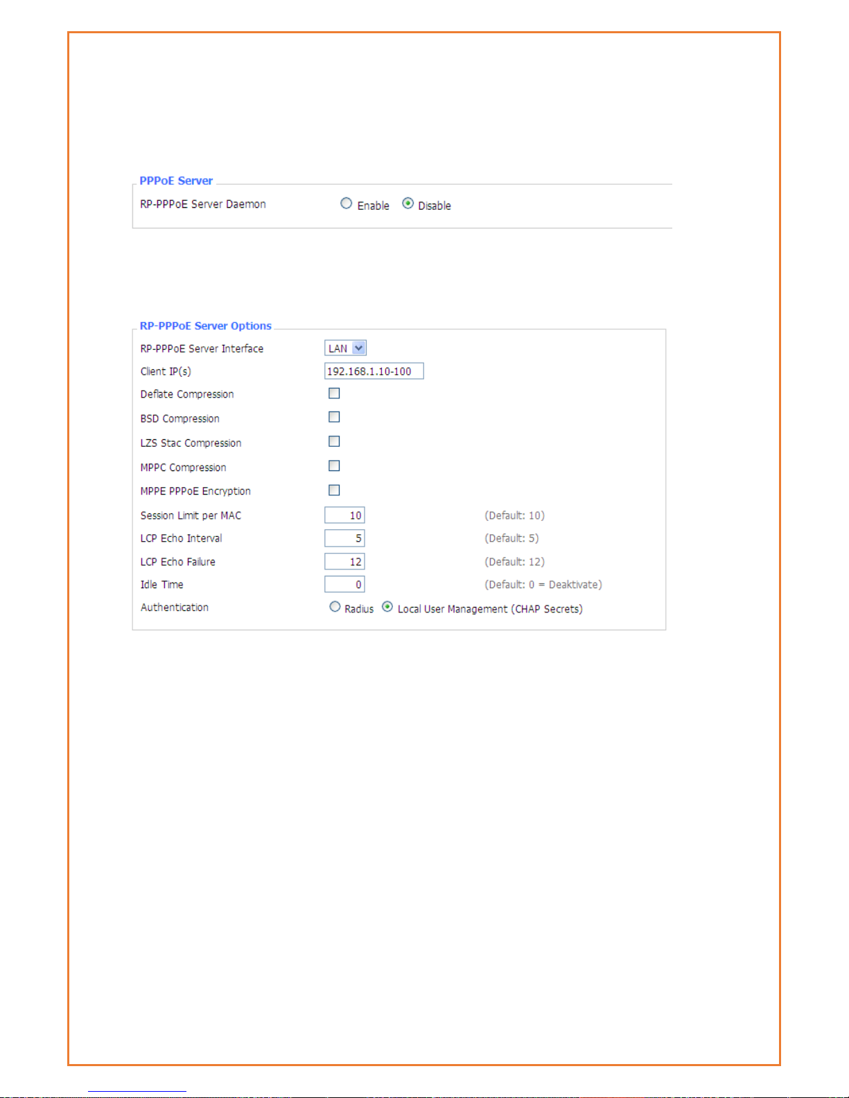
PPOE Server
PPPoE Server
RP-PPPoEServer Daemon: enable or disable PPPoE server
RP-PPPoEServer Options
PPPOE Server Interface: PPPoE server interface to the outside, only to support the LAN port
Client IP(s): IP range assigns to the PPPoE client in the format: xxx.xxx.xxx.xxx-xxx
Deflate Compression: Enable or disable Deflate Compression
BSD Compression: Enable or disable BSD Compression
LZS Stac Compression: Enable or disable LZS Stac Compression
MPPC Compression: Enable or disable MPPC Compression
MPPE PPPoE Encryption: Enable or disable MPPE PPPoE Encryption
Session Limit per MAC: Default is 10
LCP Echo Interval: Time interval to set the the LCP calibration phase response
LCP Echo Failure: Release PPPoE over failure times, the PPPoE client will need to reconnect
Idle Time: Set idle time, idle time at the appropriate time to release the PPPoE
Authentication: including local and Radius (Remote Authentication Dial In User)
Local User Management(CHAP Secrets)
Page 66

User: Set PPPOE client's user name
Password: Set PPPOE client's user password
IP Address: Set PPPOE client's user IP address
Enable: Enable or disable this setting
Radius
Radius Server IP: Set the Remote Authentication Dial in User-Server IP
Radius Authentication Port: Set the Remote Authentication Dial in User-Authentication Port
Radius Accounting Port: Set the Remote Authentication Dial in User-Accounting Port
Radius Shared Key: Transactions between the client and RADIUS accounting server are
authenticated using a shared secret, which is never sent over the network.
Advanced Networking
Routing
Operating Mode: Gateway and Router
If the Datamax is acting as your primary gateway to the internet, select
“gateway”, otherwise select “router”.
Dynamic Routing
Page 67

If you want the router to participate in dynamic routing protocols such as RIP etc
running on your network(s), you should enable this option. To enable the Dynamic
Routing feature for the WAN side, select WAN. To enable this feature for the LAN
and wireless side, select LAN&WLAN. To enable the feature for both the WAN and
LAN, select Both. To disable the Dynamic Routing feature for all network
interfaces, keep the default setting, Disable.
Note:Dynamic Routing is not available in Gateway mode
Page 68

Static Routing
Select set number: the routing table entry number
Route Name: naming rules makes your life easier!
Metric: the “cost” of this route – lower numbers are preferred routes.
Destination LAN NET: the new route destination address
Subnet Mask: the subnet mask for the new route
Gateway: IP address of the gateway device that forwards packets to the
destination host or network.
Interface: The interface that has the gateway attached (LAN/WLAN, WAN, or
loopback)
Show Routing Table
Mac address Clone
Some ISPs lock service provision to a MAC address. By cloning the MAC address,
you can insert the Datamax into the network path without needing to update
your MAC address with your ISP.
Page 69

Clone MAC address can clone three parts: Clone LAN MAC, Clone WAN MAC,
Clone Wireless MAC.
Note: MAC addresses are 48 characters, they cannot be set to a multicast
address, and the first byte must be even. The MAC address value of network
bridge br0 is determined by the lower order bits of wireless MAC address and LAN
port MAC address.
Vlan
VLAN’s allow users to specify which ports are “bridged” – that is, where broadcast
traffic will be shared. This allows users to create separate subnets on each LAN
port (or group of LAN ports). Note that although there are 15 VLAN’s available,
there are only 5 ports (4 x LAN, 1 x WAN). Note also that the WAN port should be
on a separate VLAN or routing to the WAN may not work. If the WAN port is
assigned to the same VLAN as the LAN ports, then it becomes an additional LAN
port and cannot be used for a WAN connection.
Page 70

QOS Basic
Bandwidth management prioritizes the traffic on router. Interactive traffic (telephony,
browsing, telnet, etc.) gets priority and bulk traffic (file transfer, P2P) gets low priority.
The main goal is to allow both types to live side-by side without unimportant traffic
disturbing more critical things. All of this is automatic.
QoS allows control of the bandwidth allocation to different services, netmasks, MAC
addresses and the four LAN ports.
Page 71
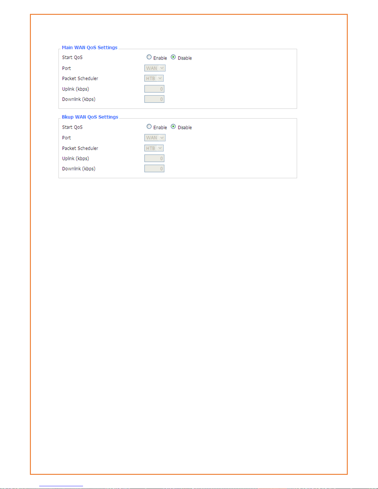
Uplink (kbps):To use bandwidth management (QoS) users must enter bandwidth values for
their uplink. These are generally 80% to 90% of your maximum bandwidth.
Downlink (kbps):To use bandwidth management (QoS) users must enter bandwidth values for
their downlink. These are generally 80% to 90% of your maximum bandwidth.
HTB Settings - Hierarchical Token Bucket, it is a faster replacement for the CBQ qdisc in Linux.
HTB helps in controlling the use of the outbound bandwidth on a given link. HTB allows you to use
one physical link to simulate several slower links and to send different kinds of traffic on different
simulated links. In both cases, users must specify how to divide the physical link into simulated
links and how to decide which simulated link to use for a given packet to be sent. In other words,
HTB is useful for limiting a client's download/upload rates, thereby preventing his monopolization
of the available bandwidth.
Page 72

QOS Classic
Netmask Priority
Users may specify priority for all traffic from a given IP address or IP Range.
Check all values and click Save Settings to save settings. Click the Cancel changes button to cancel
unsaved changes.
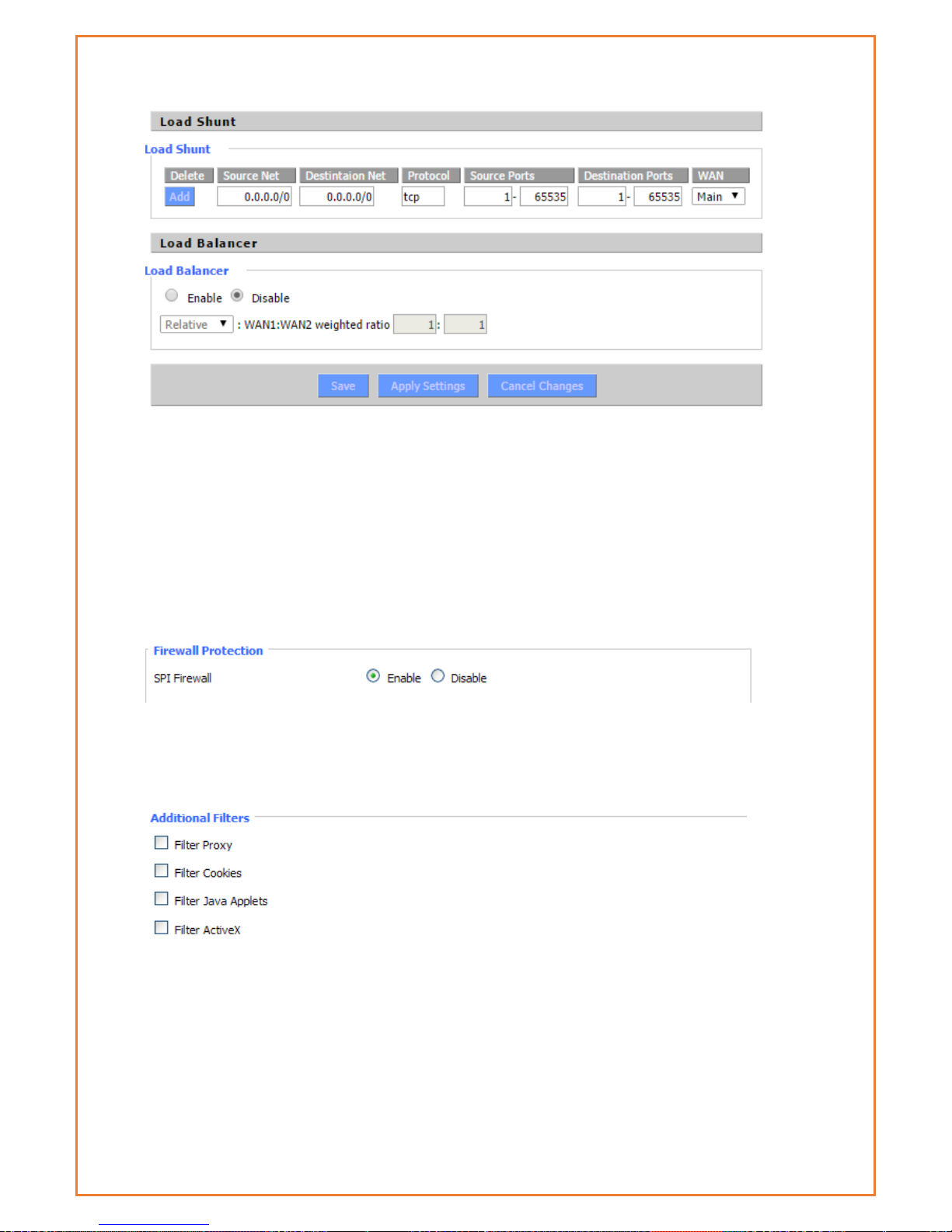
3.1.8.2 Load Arrange
Page 73
Security
Firewall
Users can enable or disable the firewall, filter specific Internet data types, and prevent
anonymous Internet requests, ultimately enhance network security.
Firewall Protection
Firewall enhance network security and use SPI to check the packets into the network. To use
firewall protection, choose to enable otherwise disabled. Only enable the SPI firewall, users can
use other firewall functions: filtering proxy, block WAN requests, etc.
Additional Filters
Filter Proxy: Wan proxy server may reduce the security of the gateway; Filtering Proxy will refuse
any access to any wan proxy server. Click the check box to enable the function otherwise
disabled.
Filter Cookies: Cookies are the website of data the data stored on your computer. When users
interact with the site, the cookies will be used. Click the check box to enable the function
otherwise disabled.
Page 74

Filter Java Applets: If refuse to Java, you may not be able to open web pages using the Java
programming. Click the check box to enable the function otherwise disabled.
Filter ActiveX: If refuse to ActiveX, users may not be able to open web pages using the ActiveX
programming. Click the check box to enable the function otherwise disabled.
Prevent WAN Request
Block Anonymous WAN Requests (ping): By selecting “Block Anonymous WAN Requests (ping)”
box to enable this feature, users can prevent your network from the Ping or detection of other
Internet users. so, that make More difficult to break into users network. The default state of this
feature is enabled, choose to disable allow anonymous Internet requests.
Filter IDENT (Port 113): Enable this feature can prevent port 113 from being scanned from
outside. Click the check box to enable the function otherwise disabled.
Block WAN SNMP access: This feature prevents the SNMP connection requests from the WAN.
After Complete the changes, click the Save Settings button to save your changes. Click the Cancel
Changes button to cancel unsaved changes.
Impede WAN DoS/Bruteforce
Limit ssh Access: This feature limits the access request from the WAN by ssh, and per minute up
to accept two connection requests on the same IP. Any new access request will be automatically
dropped.
Limit Telnet Access: This feature limits the access request from the WAN by Telnet, and per
minute up to accept two connection requests on the same IP. Any new access request will be
automatically dropped.
Limit PPTP Server Access: When build a PPTP Server in the router, this feature limits the access
request from the WAN by ssh, and per minute up to accept two connection requests on the same
IP. Any new access request will be automatically dropped.
Limit L2TP Server Access: When build a L2TP Server in the router, this feature limits the access
request from the WAN by ssh, and per minute up to accept two connection requests on the same
IP. Any new access request will be automatically dropped.
Log Management
The router can keep logs of all incoming or outgoing traffic for your Internet connection.
Page 75

Log: To keep activity logs, select Enable. To stop logging, select Disable. When select enable, the
following page will appear.
Log Level: Set this to the required log level. Set Log Level higher to log more actions.
Options: When select Enable, the corresponding connection will be recorded in the journal, the
disabled are not recorded.
Incoming Log: To see a temporary log of the Router's most recent incoming traffic, click the
Incoming Log button.
Outgoing Log: To see a temporary log of the Router's most recent outgoing traffic, click the
Outgoing Log button.
Click the Save Settings button to save your changes. Click the Cancel Changes button to cancel
unsaved changes.
Page 76
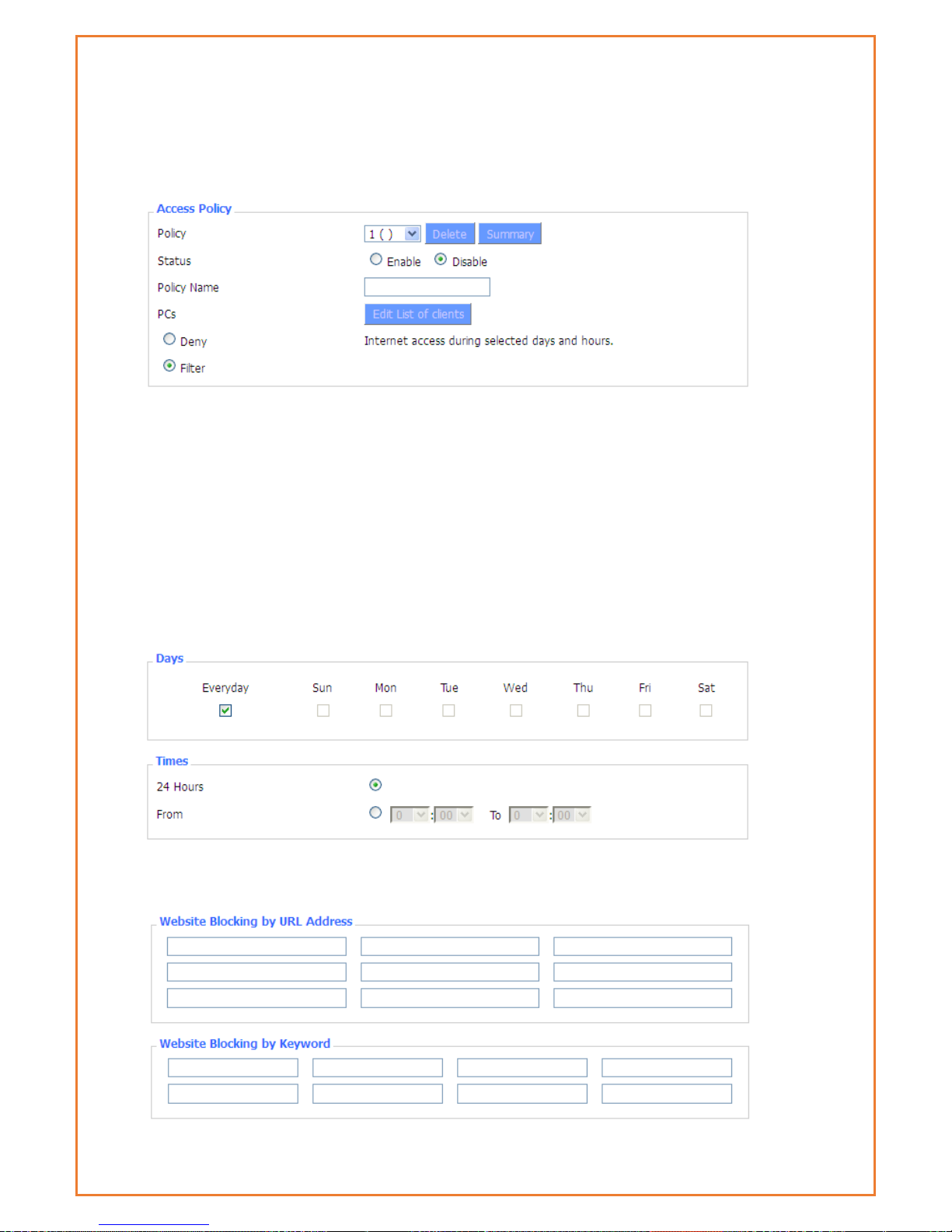
WAN Access Restrictions
Users can block or allow specific types of Internet applications. They can set specific PC-based
Internet access policies. This feature allows users to customize up to ten different Internet Access
Policies for particular PCs, which are identified by their IP or MAC addresses.
Two options in the default policy rules: "Filter" and "reject". If select "Deny”, modem will deny
specific computers to access any Internet service at a particular time period. If you choose to
"filter”, it will block specific computers to access the specific sites at a specific time. You can set
up 10 Internet access policies filtering specific PCs access Internet services at a particular time
period.
Access Policy: Users may define up to 10 access policies. Click Delete to delete a policy or
Summary to see a summary of the policy.
Status: Enable or disable a policy.
Policy Name: Users may assign a name to your policy.
PCs: The part is used to edit client list, the strategy is only effective for the PC in the list.
Days: Choose the day of the week you would like your policy to be applied.
Times: Enter the time of the day you would like your policy to be applied.
Page 77
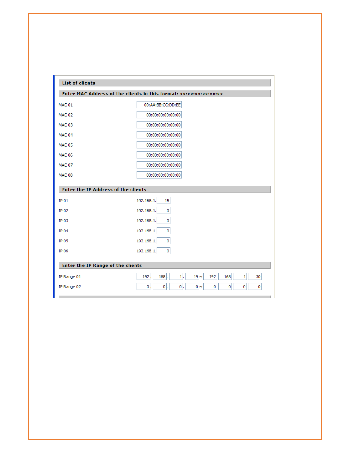
Website Blocking by URL Address: Users can block access to certain websites by entering their
URL.
Website Blocking by Keyword: You can block access to certain website by the keywords
contained in their webpage
set up Internet access policy
1. Select the policy number (1-10) in the drop-down menu.
2. For this policy is enabled, click the radio button next to "Enable"
3. Enter a name in the Policy Name field.
4. Click the Edit List of PCs button.
5. On the List of PCs screen, specify PCs by IP address or MAC address. Enter the appropriate IP
addresses into the IP fields. If you have a range of IP addresses to filter, complete the
appropriate IP Range fields. Enter the appropriate MAC addresses into the MAC fields.
6. Click the Apply button to save your changes. Click the Cancel button to cancel your unsaved
changes. Click the Close button to return to the Filters screen.
7. If users want to block the listed PCs from Internet access during the designated days and time,
then keep the default setting, Deny. If you want the listed PCs to have Internet filtered during
the designated days and time, then click the radio button next to Filter.
8. Set the days when access will be filtered. Select every day or the appropriate days of the
Page 78

week.
9. Set the time when access will be filtered. Select 24 Hours, or check the box next to From and
use the drop-down boxes to designate a specific time period.
10. Click the Add to Policy button to save your changes and active it.
11. To create or edit additional policies, repeat steps 1-9.
12. To delete an Internet Access Policy, select the policy number, and click the Delete button.
Note:
1) The default factory value of policy rules is "filtered". If the user chooses the default policy
rules for "refuse", and editing strategies to save or directly to save the settings. If the
strategy edited is the first, it will be automatically saved into the second, if not the first,
keep the original number.
2) Turn off the power of the router or reboot the router can cause a temporary failure After
the failure of the router, if cannot automatically synchronized NTP time server, you need
to recalibrate to ensure the correct implementation of the relevant period control
function.
URL Filtering
Users can block access to certain websites by entering their URL.
Page 79
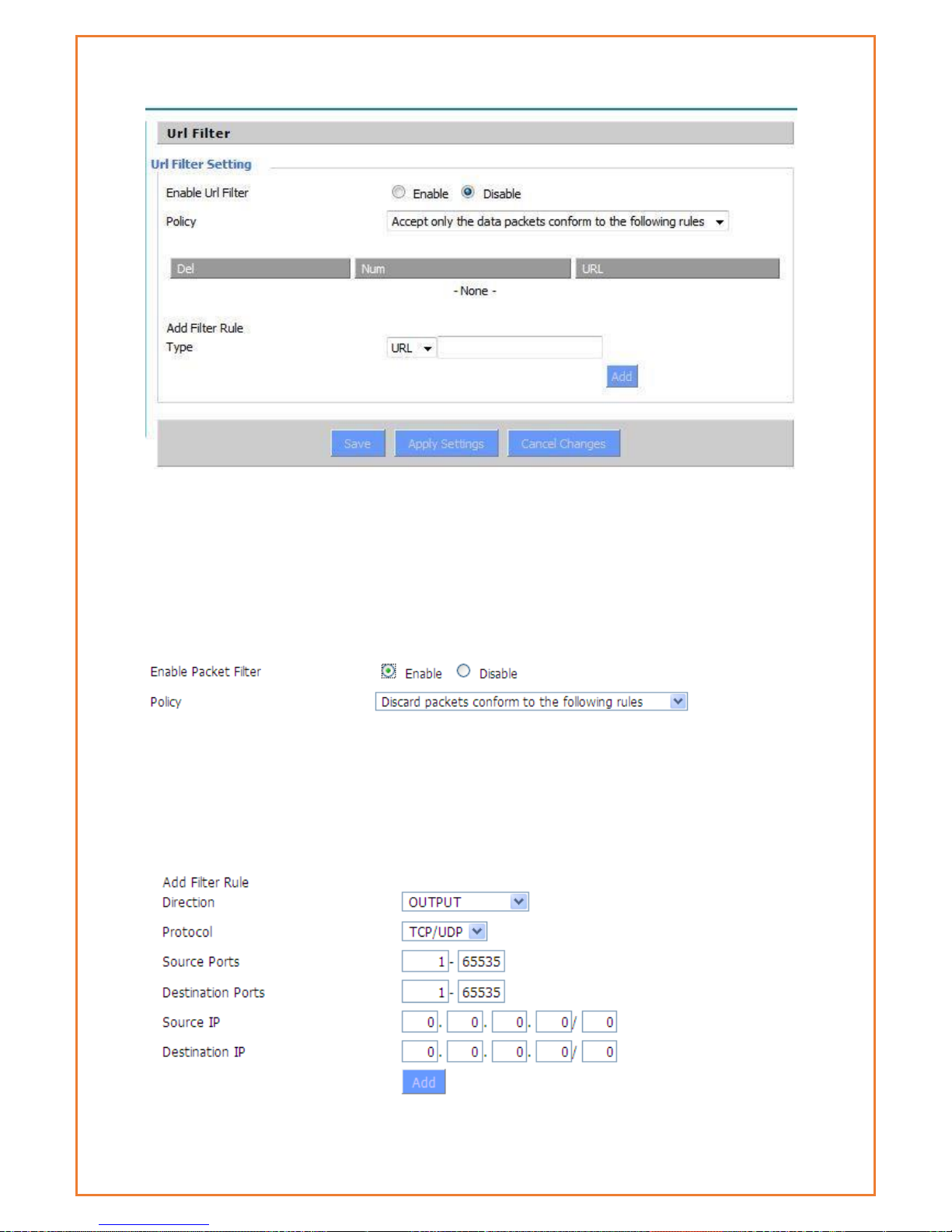
Packet Filtering
Packet filtering allows modem to block some packets getting Internet access or block some
Internet packets getting local network access, Users can configure filter items to block these
packets.
Packet Filter
Packet filter function is realized based on IP address or port of packets.
Enable Packet Filter: Enable or disable “packet filter” function
Policy: The filter rule’s policy, you can choose the following options
Discard the Following--Discard packets conform to the following rules, Accept all other packets
Only Accept the Following-- Accept only the data packets conform to the following rules,
discard all other packets
Page 80

Direction
Input: packet from WAN to LAN
output: packet from LAN to WAN
Protocol : packet Protocol type
Source Ports : packet's source port
Destination Ports : packet's destination port
Source IP: packet's source IP address
Destination IP: packet's destination IP address
Note: "Source Port" ,"Destination Port" ,"Source IP" ,"Destination IP" could not be all empty ,you
have to input at least one of these four parameters.
Serial Applications
There is a console port on the Maxon MA100-1010. Normally, this port is used to debug the
router. This port can also be used as a serial port. The router has embedded a serial to TCP
program. The data sent to the serial port is encapsulated by TCP/IP protocol stack and then is
sent to the destination server. This function can work as a Maxon DTU (Data Terminal Unit).
Please refer www.maxon.com.au for more information about this product.
Baudrate: The serial port’s baud rate
Databit: The serial port’s data bit
Page 81

Stop bit: The serial port’s stop bit
Parity: The serial port’s parity
Flow Control: The serial port’s flow control type.
Enable Serial TCP Function: Enable the serial to TCP function
Protocol Type: The protocol type to transmit data.
UDP(DTU) – Data transmit with UDP protocol, work as a Maxon DTU which
has application protocol and hear beat mechanism.
Pure UDP – Data transmit with standard UDP protocol.
TCP(DTU) -- Data transmit with TCP protocol, work as a Maxon DTU which
has application protocol and hear beat mechanism.
Pure TCP -- Data transmit with standard TCP protocol, router is the client.
TCP Server -- Data transmit with standard TCP protocol, router is the server.
TCST -- Data transmit with TCP protocol, Using a custom data
Server Address: The data service centre’s IP Address or domain name.
Server Port: The data service centre’s listening port.
Device ID: The router’s identity ID.
Device Number: The router’s phone number.
Heartbeat Interval: The time interval to send heart beat packet. This item is valid only
when you choose UDP(DTU) or TCP(DTU) protocol type.
TCP Server Listen Port: This item is valid when Protocol Type is “TCP Server”
Custom Heartbeat Packet: This item is valid when Protocol Type is “TCST”
Custom Registration Packets: This item is valid when Protocol Type is “TCST”
maXconnect
maXconnet is device management portal. It is a cloud based M2M management portal
which allows you to access, monitor and control 3G/4G Maxon devices securely. With
maXconnect you can access real-time data from your devices, monitor their status and
location. Utilize complete functionality by controlling your devices anywhere, anytime.
This one stop portal is an access point to manage your 3G/4G assets securely and
remotely.
maXconnect can be used when the device is connected to the Internet or within maXwan. When
an Internet connection is used, the updates should go to portal.maxconnect.com.au and the ftp
from updates.maxconnect.com.au. When using maXwan the updates should go to 10.0.0.1 and
the ftp updates from 10.0.0.32. This feature is enable by default in firmware 3.0.2 or later.
Page 82
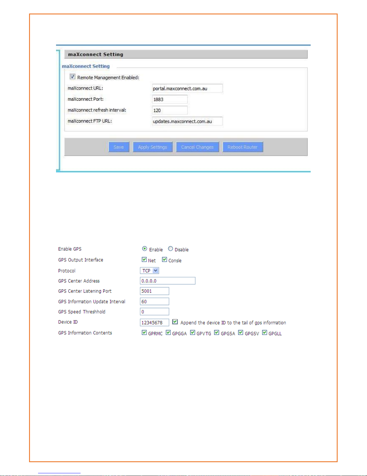
GPS
This menu allows users to enable and disable GPS function in the modem.
Enable GPS:Enable or disable GPS function
GPS Output Interface:This item selects the GPS output interface including network and serial
port
Protocol:TCP mode or UDP mode
GPS Centre Address:The GPS centre’s IP Address or domain name
GPS Centre Listening Port:The GPS centre’s listening port.
GPS Information Update Interval:The time interval between two GPS information update, unit
is second
Page 83
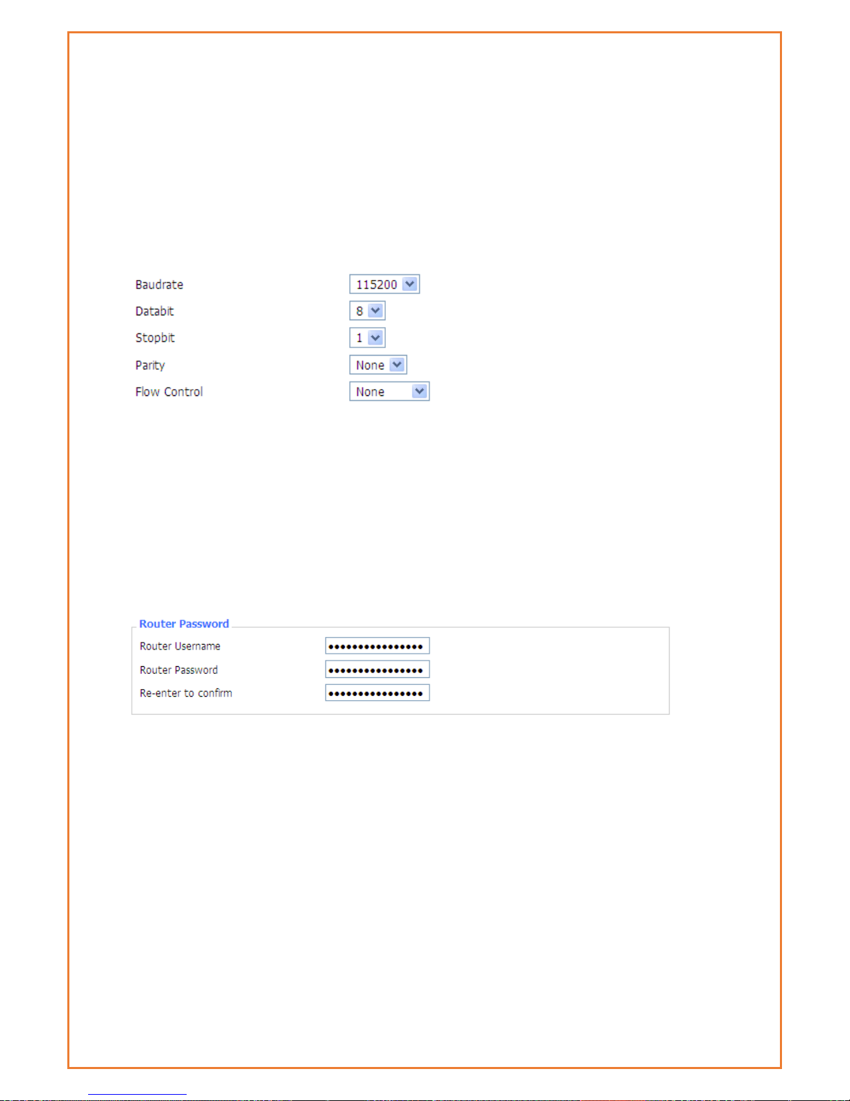
GPS Speed Threshhold:The GPS speed threshold of update GPS information
Device ID:The ID of this device
Append the device ID to the tail of GPS information: Whether append the ID to the GPS
information
GPS Information Contents: Contents selection
When GPS output interface is serial port, we should set the following serial port settings:
Administration
Management
The Management screen allows users to change the router's settings. On this page, users will find
most of the configurable items of the router code.
The new password must not exceed 32 characters in length and must not include any spaces.
Enter the new password a second time to confirm it.
Note:Default username and password is admin.
It is strongly recommended that users to change the factory default password of the router,
all users who try to access the router's web port will be prompted for the router's password.
Web Access
This feature allows you to manage the router using either HTTP protocol or the HTTPS protocol. If
users choose to disable this feature, a manual reboot will be required. You can also activate or
not the router information web page. It's now possible to password protect this page (same
username and password than above).
Page 84

Protocol:This feature allows users to manage the router using either HTTP protocol or the
HTTPS protocol
Auto-Refresh:Adjusts the Web GUI automatic refresh interval. 0 disables this feature
completely
Enable Info Site:Enable or disable the login system information page
Info Site Password Protection:Enable or disable the password protection feature of the system
information page
Remote Access: This feature allows users to manage the router from a remote location, via the
Internet. To disable this feature, keep the default setting, Disable. To enable this feature select
Enable and use the specified port (default is 8080) on your PC to remotely manage the router.
You must also change the router's default password to one of your own, if you haven't already.
To remotely manage the router, enter http://xxx.xxx.xxx.xxx:8080 (the x's represent the router's
Internet IP address, and 8080 represents the specified port) in your web browser's address field.
You will be asked for the router's password.
If users use https you need to specify the URL as https://xxx.xxx.xxx.xxx:8080 (not all firmware’s
does support this without rebuilding with SSL support).
SSH Management:You can also enable SSH to remotely access the router by Secure Shell. Note
that SSH daemon needs to be enable in Services page.
Note:
If the Remote Router Access feature is enabled, anyone who knows the router's Internet IP
address and password will be able to alter the router's settings.
Telnet Management:Enable or disable remote Telnet function
Page 85

Cron:The cron subsystem schedules execution of Linux commands. You'll need to use the
command line or start up scripts to actually use this.
Schedule Reboot & Shutdown
Modem can be scheduled to reboot and shutdown on specific day and time. Users can schedule
regular shutdown and boot for the router.
At a specific date time match the weekday or match the mon day shutdown.
At a specific date time match the weekday and the mon day boot
For date, based shutdown and boot Cron must be activated. See Management for Cron activation.
Users can schedule regular reboots of the router on regular intervals after XXX seconds, at a
specific date time, each week or every day.
Page 86

SMS Function
This function allows users to remotely retrieve modem’s signal strength, WAN IP address,
remotely reboot the modem, change APN and configure WAN username and password via SMS.
This function is enabled by default. Phone number added to the below list can only send SMS to
the modem. If no phone number is configured, modem accepts message from any phone number
and process it accordingly. Modem will send acknowledgement of SMS message. The phone
numbers must be in International format only.
Page 87

Syntax
Comment
DATAMAX.MAXON.WANIP
To retrieve WAN IP
DATAMAX.MAXON.REBOOT
To reboot modem
DATMAX.MAXON.APN=” APN name here”
To setup modem APN
DATAMAX.MAXON.RSSI
To retrieve modem’s signal strength
DATAMAX.MAXON. USERNAME=” Username
here”
TO configure WAN username
DATAMAX.MAXON. PASSWORD=” Password
here”
TO configure WAN password
Web logs
Web logs display modem debugging logs. To get more details on debugging logs please enable
console logs under Services.
Shell Commands
Run Command: Users can run command lines via the web interface. Fill the text area with your
command and click Run Commands to submit.
Startup:Users save some command lines to be executed at start-up’s router. Fill the text area
with commands (only one command by row) and click Save Start-up.
Shutdown:Users can save some command lines to be executed at shutdown's router. Fill the
text area with commands (only one command by row) and click Save Shutdown.
Firewall:Each time the firewall is started, it can run some custom iptables instructions. Fill the
text area with firewall's instructions (only one command by row) and click Save Firewall.
Custom Script Custom script is stored in /tmp/custom.sh file. Users ca run it manually or use
cron to call it. Fill the text area with script's instructions (only one command by row) and click
Save Custom Script.
Page 88

Firmware upgrade
Firmware upgrade allows users to upgrade or downgrade firmware. It may take few minutes to
upgrade the firmware therefore please be patient and keep monitoring the upgrade bar, modem
will come back online after performing upgrade. The configuration will not be erased.
Page 89

Backup and Restore
Users can backup current configuration using Backup button and restore the settings using
restore button. Restore configurations with files backed up using the same firmware and same
model of router.
Factory Default
Factory default settings allow user to revert setting to factory settings. The modem erase current
configuration and load the factory settings in the modem. It is recommended to backup setting
before performing factory settings. To perform factory reset, click on “Yes” button, Apply the
settings and reboot the modem.
Page 90

Reboot
This menu allows modem to perform soft reboot of the modem. When user change any settings,
modem should reboot.
 Loading...