

Page 1

User Manual CM70
Declaration of Conformity
We, MAXON CIC Europe Ltd, hereby declare under our sole responsibility, that the product:
CB-Radio MAXON CM10/CM70
complies with all the technical regulations applicable to the product in accordance with EU Council
Directives, European Standards and national frequency applications:
73/23/EEC, 89/336/EEC and 99/5/EC
EN 300 135-2 / EN 300 433-2
EN 301 489-1, EN 301 489-13, EN 69050-1
Due to the absence of a harmonised standard covering frequency applications, this CB radio may be used on a frequency
band allowed in the country where the product is used.
An individual licence is required for operating this radio in AM/FM on 40/40 channel in Belgium (BE), Switzerland
(CH), Spain (ES) and Italy (IT).
In Germany (DE) 80/12, 80/40, 40/12 or 40/40 FM/AM channels are allowed; Czech Republic (CZ) 80 FM only;
Estonia (ES), Finland (FI), France (FR), Ireland (IE), Latvia (LV) Netherlands (NL) Poland (PL), Portugal
(PT), and Slovakia (SK) the operation on 40/40 channels in AM/FM is licence free and free of charge.
All essential radio test suites have been carried out.
CEPT 40CH FM only may be used licence and charges free in ALL EU Member States including Norway (NO) &
Iceland (IS), except Austria, where CB radios with multi standard programmable bands are not allowed ,
and Italy and Malta, where individual licence is required.
In order to use this radio in Belgium, Spain and Switzerland, residence must have an individual licence. Users coming
from abroad to these countries may freely use the radio in FM mode, while in order to use it in AM mode, they must hold
a licence released in their own country.
In Great Britain (UK) there is no longer a requirement to possess a Wireless Telegraphy (WT) Act Licence to operate
Citizens' Band Radio equipment, providing that the equipment is operated in accordance with the WT (Exemption)
(Amendment) Regulations 2006.
In Germany, in some border areas, CB radio cannot be used as a base station from channel 41-80. (Refer to local
authority (notification office) for details. Travellers arriving in Italy must get an Italian Authorization.
travellers from Germany is necessary in Spain, Finland, Switzerland and Liechtenstein.
Maxon CIC Europe Ltd declares, under their sole responsibility that this apparatus fulfils the requirement of Directive
99/5/EC of the European Parliament and the 9 Council of March of 1999, transposed to the Spanish legislation by means
of Real Decree 1890/2000, on November 20th.
Maxon CIC Europe Ltd declara, bajo su responsabilidad, que este aparato cumple con lo dispuesto en la Directiva 99/5/EC
del Parlamento Europeo y del Consejo de 9 Marzo de 1999, transpuesta a la legislación española mediante el Real Decreto
1890/2000, de 20 de noviembre.
Maxon House, Cleveland Road
Hemel Hempstead, Herts. HP2 7EY
United Kingdom
----------------------------------------------
Hugh Han
Managing Director
June 2008
Page 68 of 68
Circulation Card for
D
D
D
e
e
e
c
c
c
l
l
l
a
a
a
r
r
r
a
a
a
t
t
t
i
i
i
o
o
o
n
n
n
o
o
o
f
f
f
C
C
C
o
o
o
n
n
n
f
f
f
o
o
o
r
r
r
m
m
m
i
i
i
t
t
t
y
y
y
Page 2

User Manual CM70
Main Schematic Drawing
Page 67 of 68
M
M
M
a
a
a
i
i
i
n
n
n
s
s
s
c
c
c
h
h
h
e
e
e
m
m
m
a
a
a
t
t
t
i
i
i
c
c
c
Page 3

User Manual CM70
Compander Circuit
Page 66 of 68
C
C
C
o
o
o
m
m
m
p
p
p
a
a
a
n
n
n
d
d
d
e
e
e
r
r
r
c
c
c
i
i
i
r
r
r
c
c
c
u
u
u
i
i
i
t
t
t
Page 4

User Manual CM70
Block Diagram
Page 65 of 68
B
B
B
l
l
l
o
o
o
c
c
c
k
k
k
D
D
D
i
i
i
a
a
a
g
g
g
r
r
r
a
a
a
m
m
m
Page 5

User Manual CM70
Diagrams (Bottom Layout)
Page 64 of 68
B
B
B
o
o
o
t
t
t
t
t
t
o
o
o
m
m
m
L
L
L
a
a
a
y
y
y
o
o
o
u
u
u
t
t
t
Page 6

User Manual CM70
Diagrams (Top Layout)
Page 63 of 68
T
T
T
o
o
o
p
p
p
L
L
L
a
a
a
y
y
y
o
o
o
u
u
u
t
t
t
Page 7

User Manual CM70
Updated Information on National Restrictions
BELGIUM, SPAIN and SWITZERLAND
In order to use this transceiver in Belgium, Spain and Switzerland, users must have an individual
licence. Users coming from abroad may freely use the radio in FM mode, while in order to use it
in AM mode they must hold a licence issued in their country of residence.
UK
As of the 8 December 2006 there is no longer a requirement to possess a WT Act licence to
operate Citizens Band Radio equipment in the UK.
ITALY
Foreigners arriving in Italy must get an Italian authorisation.
AUSTRIA
Austria does not allow using multi standard programmable CB radios. It is recommended that
users carefully follow this directive and not to use the product in the Austrian territory.
GERMANY
Along some border areas in Germany, the radio can not be used as a base station from
Channel 41 to channel 80. Refer to local authority (notification office) for details.
English
Page 62 of 68
N
N
N
a
a
a
t
t
t
i
i
i
o
o
o
n
n
n
a
a
a
l
l
l
R
R
R
e
e
e
s
s
s
t
t
t
r
r
r
i
i
i
c
c
c
t
t
t
i
i
i
o
o
o
n
n
n
s
s
s
Page 8

User Manual CM70
Table of Restrictions
The following information is only to be used as an indication. They are believed to be correct at
the time of printing this manual. It is however the user’s responsibility to check that, in the
country where radio is used, providing the regulations for the use of CB transceivers have not
been modified. It is therefore suggested that the user contact the local dealer or local authority,
in order to check the current regulations for the use of CB transceivers, before operating this
product. The manufacturer does not accept any responsibility if the product is used in violation of
the regulations of the country where the product is used.
This product is intended for use in all EU Member States and all EFTA countries see restrictions below.
Country Restrictions on use of CB transceivers Settings
Austria Not allowed NOT ALLOWED
Belgium
Czech Rep. 40/80 CH FM - Free use. AM Channels not allowed CE
Denmark 40 CH 4W FM - Free use CE
Cyprus/Estonia 40 CH 4W FM / 40 CH 1W AM - Free use CE
Finland 40 CH 4W FM / 40 CH 1W AM - Free use EU FR CE
France 40 CH 4W FM / 40 CH 1W AM - Free use EU FR CE
Germany
Lithuania
Latvia 40 CH 4W FM / 40 CH 1W AM - Free use CE
Luxembourg
Norway 40 CH 4W FM - Free use CE
Netherlands 40 CH 4W FM / 40 CH 1W AM - Free use EU FR CE
Poland/Portugal 40 CH 4W FM / 40 CH 1W AM - Free use EU FR CE
Slovakia/Slovenia 40 CH 4W FM / 40 CH 1W AM - Free use CE
Switzerland/
Liechtenstein
Page 61 of 68
40 CH 4W FM / 40 CH 1W AM - Individual licence is required;
40 CH AM is allowed under home licence.
80 CH 4W FM - Free use (restrictions for use as a base station on channels
41-80 in some border areas)
12 CH - 1W AM - Free use
40 CH 1W AM - Free use (only CH 4-15 allowed) EU
40 CH 4W FM / 12 CH 1W AM - Free use D2 CE
REGTP Vfg41 issued on September 10, 2003
40 CH 4W FM / 40 CH 4W AM - Free use CEGreece
T/R 20-02
40 CH 4W FM - Free use CEHungary/
AM Channels not allowed
40 CH 4W FM / 40 CH 4W AM - Free use SP EU FR 10 CEIreland
S.I. No. 436 of 1998. Wireless Telegraphy Act, 1926 (Sec 3) Exemption of
Citizens' Band (CB) Radios) Order, 1998
40 CH 4W FM / 40 CH 1W AM - A declaration to the Italian Ministry is
Italy
required (art. 145 - dl 259 of 10/08/2003)
34 CH - 4W FM, 1W AM (erp). Note: AM mode allowed on CH1- CH23 only.
General authorisation is required (art. 104 - dl 259 of 01/08/2003)
P.N.F. issued on DM 08.07.02 Notes: 49 A/B/C/D/E/G
40 CH 4W FM - Free use. (Following frequencies are not allowed: 29.995,
27.045, 27.095, 27.145, 27.195 MHz)
40 CH 4W FM - Individual licence is required CEMalta
AM channels not allowed
40 CH 4W FM - Licence Exempt UK CEUnited Kingdom
AM channels not allowed
40 CH 4W FM / 40 CH 4W AM - Individual licence is required SP EU FR CESpain
Ministerial decree of 18 November 2002 issued by "Secretaria de Estado de
Telecomunicaciones y para la Sociedad de la información"
40 CH 4W FM - Free use CESweden
40 CH 1W AM - Individual licence is required
40 CH 4W FM - Individual licence is required
40 CH 1W AM - Individual licence is required
EU FR CE
DE
EU FR
SP EU FR 10 CE
EU FR
EU FR CE
12
CE
T
T
T
a
a
a
b
b
b
l
l
l
e
e
e
o
o
o
f
f
f
R
R
R
e
e
e
s
s
s
t
t
t
r
r
r
i
i
i
c
c
c
t
t
t
i
i
i
o
o
o
n
n
n
s
s
s
Page 9

User Manual CM70
j
Tabela czĊstotliwoĞci
Radiotelefon CM70 jest wyposaĪony w nowoczesny ukáad programowania obsáugujący wiele standardów,
który umoĪliwia programowanie róĪnych pasm czĊstotliwoĞci, parametrów technicznych i trybów pracy
zgodnie z przepisami obowiązującymi w kraju, w którym urządzenie jest uĪywane. DostĊpnych jest 10
programowanych pasm czĊstotliwoĞci przedstawionych w poniĪszej tabeli:
OZNACZENIE
KRAJU
I0 WàOCHY 40 kanaáów AM / FM 4W
I2 WàOCHY 36 kanaáów AM / FM 4W
DE NIEMCY 80 kanaáów FM 4W – 12 kanaáów AM 1W
D2 NIEMCY 40 kanaáów FM 4W – 12 kanaáów AM 1W
EU EUROPA 40 kanaáów FM 4W – 40 kanaáów AM 1W
CE CEPT 40 kanaáów FM 4W
SP HISZPANIA
FR FRANCJA 40 kanaáów FM 4W – 40 kanaáów AM 1W
UK
PL POLSKA
Uwaga! Ten radiotelefon CB zostaá fabrycznie dostrojony do europejskiego pasma czĊstotliwoĞci (CEPT 40
kanaáów FM, 4 W), gdyĪ jest to standard obowiązujący we wszystkich krajach w Europie. ProszĊ zapoznaü
siĊ z informacjami w tabeli na stronie 1 (Ograniczenia korzystania z radiotelefonów CB w Europie).
Wyznaczanie/programowanie przedziaáu
czĊstotliwoĞci
KRAJ
WIELKA
BRYTANIA
DANE TECHNICZNE (kanaá, tryb
pracy, moc nadajnika)
40
kanaáów
AM
40 kanaáów FM 4W brytyjski zakres -40
kanaáów FM 4W europejski zakres
kanaáówAM/ FM 4W polski zakres
/ FM 4W
40
Polski
Ten radiotelefon CB musi byü zaprogramowany i dostrojony wyáącznie do pasma czĊstotliwoĞci dozwolonego
w kraju, w którym bĊdzie uĪywany. Aby dostroiü radiotelefon CB do innego pasma czĊstotliwoĞci, postĊpuj w
nastĊpujący sposób:
1) Wyáącz radiotelefon CB.
2) WciĞnij i przytrzymaj przycisk EMG podczas wáączania radiotelefonu CB za pomocą pokrĊtáa – zwolnij
przycisk gdy Ğwiecą siĊ jeszcze wszystkie symbole.
3) Kod aktualnego pasma czĊstotliwoĞci bĊdzie migaá na wyĞwietlaczu (2 znaki).
4) Teraz wybierz kod innego Īądanego pasma czĊstotliwoĞci, wciskając odpowiednio przycisk
5) WciĞnij na chwilĊ przycisk EMG, aby potwierdziü wybór i zapamiĊtaü nowe pasmo czĊstotliwoĞci.
Page 60 of 68
lubi.
T
T
T
a
a
a
b
b
b
e
e
e
l
l
l
a
a
a
C
C
C
z
z
z
e
e
e
s
s
s
t
t
t
o
o
o
t
t
t
l
l
l
i
i
i
w
w
w
o
o
o
s
s
s
c
c
c
i
i
i
Page 10

User Manual CM70
j
j
Instalacja
Przed przystąpieniem do montaĪu jednostki gáównej w samochodzie, naleĪy starannie wybraü dla niej
najlepsze miejsce. DostĊp do elementów sterujących powinien byü swobodny, a manipulacja nimi nie moĪe
utrudniaü prowadzenia pojazdu. Do zamontowania moĪe posáuĪyü obejma bĊdąca w komplecie. Obejma
powinna byü mocowana nad lub pod radiotelefonem CB, a samo urządzenie moĪna przechylaü zgodnie z
potrzebami w zaleĪnoĞci od rodzaju montaĪu (pod deską rozdzielczą lub pod sufitem kabiny pojazdu).
Wszystkie Ğruby mocujące obejmĊ muszą byü mocno dokrĊcone, aby nie poluzowaáy siĊ od wibracji podczas
jazdy.
Instalacja radiotelefonu CB
Przed podáączeniem zasilania upewnij siĊ, Īe radiotelefon CB jest wyáączony. Kabel zasilający wyposaĪony
jest w uchwyt bezpiecznika, przy czym bezpiecznik zainstalowano na przewodzie (+). Podáącz kabel
zasilający do ukáadu zasilającego samochodu, zwracając szczególną uwagĊ na wáaĞciwą polaryzacjĊ, nawet
jeĞli radiotelefon CB posiada odpowiednie zabezpieczenia. Podáącz czerwony przewód do bieguna dodatniego
(+), a czarny przewód do bieguna ujemnego (-) ukáadu zasilającego samochodu. Upewnij siĊ, Īe przewody i
záączki są solidnie przymocowane, aby kable nie wysuwaáy siĊ i nie powodowaáy zwarü.
Instalacja anteny
Polski
NaleĪy uĪyü anteny przenoĞnej pracującej w paĞmie 27 MHz. AntenĊ powinien zainstalowaü doĞwiadczony
technik lub pracownik centrum serwisowego. NaleĪy zwróciü szczególną uwagĊ na dokáadny montaĪ anteny
na samochodzie, zapewniający dobre jej uziemienie. Przed podáączeniem anteny do radiotelefonu naleĪy
sprawdziü jej wáaĞciwe dziaáanie miernikiem wspóáczynnika fali stojącej (SWR). NiewáaĞciwe dziaáanie anteny
moĪe uszkodziü ukáad odbiornika w radiotelefonie CB. AntenĊ naleĪy zamontowaü w najwyĪszym
niezasáoniĊtym punkcie pojazdu, jak najdalej od wszelkich Ĩródeá zakáóceĔ elektrycznych i
elektromagnetycznych. Przewód antenowy nie moĪe byü uszkodzony ani przyciĞniĊty na caáej dáugoĞci od
anteny do radiotelefonu CB. NaleĪy okresowo kontrolowaü pracĊ anteny i mierzyü wspóáczynnik fali stojącej
(SWR). Podáącz przewód koncentryczny do záącza antenowego umieszczonego na panelu tylnym
radiotelefonu CB.
Sprawdzenie dziaáania
Po podáączeniu radiotelefonu CB do ukáadu zasilającego pojazdu i anteny, naleĪy sprawdziü poprawnoĞü
dziaáania urządzenia. ProszĊ wykonaü nastĊpujące czynnoĞci:
41.) SprawdĨ, czy urządzenie zostaáo wáaĞciwie zainstalowane.
42.) SprawdĨ czy przewód zasilający jest wáaĞciwie podáączony.
43.) SprawdĨ, czy koncentryczny przewód antenowy jest wáaĞciwie podáączony.
44.) Podáącz mikrofon do gniazda (umieszczonego na panelu przednim radiotelefonu CB).
45.) Wáącz radiotelefon CB i wybierz pasmo czĊstotliwoĞci wykorzystywane w danym kraju (patrz str.
10)
46.) Wyreguluj automatyczną blokadĊ szumów (szum z gáoĞnika) przyciskiem MODE, wybierz blokadĊ
przeciwtrzaskową SQ i uĪyj przycisków
47.) Wybierz Īądany kanaá za pomocą przycisków
48.) WciĞnij przycisk PTT, aby nadawaü i zwolnij go, aby odbieraü.
lubi.
lub i.
Pozytywny efekt takiej kontroli oznacza, Īe radiotelefon CB dziaáa poprawnie. JeĞli zauwaĪysz
jakiekolwiek problemy, skontaktuj siĊ ze sprzedawcą.
Page 59 of 68
I
I
I
n
n
n
s
s
s
t
t
t
a
a
a
l
l
l
a
a
a
c
c
c
j
j
j
a
a
a
Page 11

User Manual CM70
i
j
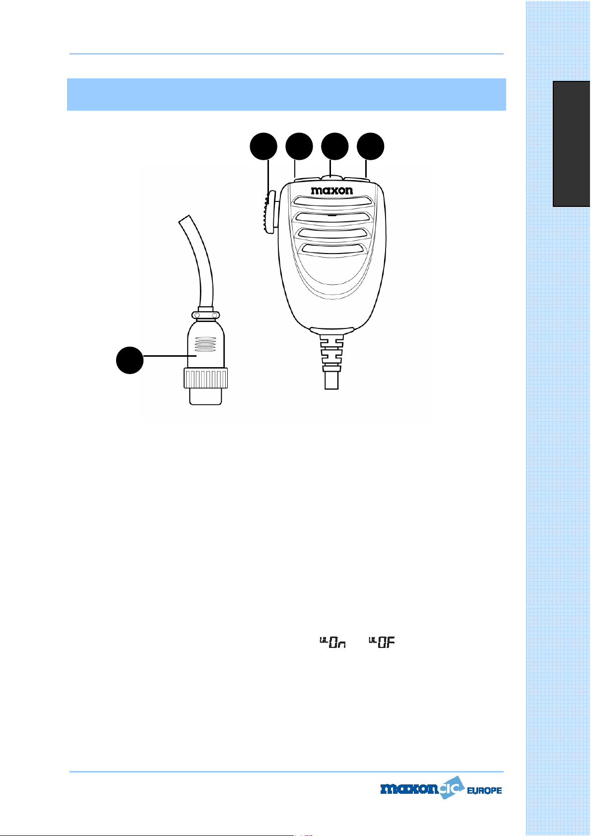
MIKROFON
1916 17 18
Polski
20
16. Przycisk wáączający nadawanie PTT
Wáącz przycisk PTT, aby rozpocząü nadawanie i wyáącz, aby powróciü do trybu odbioru.
17. Przycisk zmiany kanaáu w górĊ
Po kaĪdym naciĞniĊciu tego przycisku numer kanaáu zwiĊkszy siĊ o 1 w górĊ.
* MoĪe byü uĪywany zamiast przycisku
18. Przycisk LOCK/MODE (Blokada/Tryb pracy)
Funkcja blokowania uruchamiana po wciĞniĊciu i przytrzymaniu tego przycisku blokuje klawiaturĊ i chroni
przez przypadkowym uruchomieniem niepoĪądanych funkcji. Po wáączeniu blokady na wyĞwietlaczu pojawia
siĊ symbol LOCK.
Ten sam przycisk moĪe byü wykorzystywany w funkcji ASQ (Automatyczna blokada szumu), SQ (Blokada
przeciwtrzaskowa), BEEP TONE (Sygnaá dĨwiĊkowy), BACKLIGHT (PodĞwietlenie) i MEMORY (PamiĊü).
Przycisk ma te same moĪliwoĞci co przycisk MODE (Tryb pracy) na przednim panelu radiotelefonu CB.
* Ten sam przycisk sáuĪy do zmniejszania lub zwiĊkszania poziomu gáoĞnoĞci.
WciĞnij kilka razy przycisk LOCK/MODE, aĪ na wyĞwietlaczu pojawi siĊ symbol
Przyciskami zmiany kanaáu w dóá lub w górĊ na mikrofonie moĪna równieĪ zmniejszaü lub zwiĊkszaü poziom
gáoĞnoĞci.
19. Przycisk zmiany kanaáu w dóá
Po kaĪdym naciĞniĊciu tego przycisku numer kanaáu zmniejszy siĊ o 1 w dóá.
* MoĪe byü uĪywany zamiast przycisku
20. Wtyk mikrofonowy
6-pinowy wtyk mikrofonu (z pierĞcieniem blokującym) do podáączenia sáuchawki do gniazda mikrofonowego
na panelu przednim radiotelefonu CB.
Page 58 of 68
lub .
F
F
F
u
u
u
n
n
n
k
k
k
c
c
c
j
j
j
e
e
e
i
i
i
e
e
e
l
l
l
e
e
e
m
m
m
e
e
e
n
n
n
t
t
t
y
y
y
s
s
s
t
t
t
e
e
e
r
r
r
o
o
o
w
w
w
a
a
a
n
n
n
i
i
i
a
a
a
Page 12

User Manual CM70
12. Gniazdo EXT zewnĊtrznego gáoĞnika
To gniazdo sáuĪy do podáączenia (opcjonalnego) zewnĊtrznego gáoĞnika.
13. Gniazdo miernika poziomu sygnaáu
To gniazdo sáuĪy do podáączenia zewnĊtrznego (opcjonalnego) miernika poziomu sygnaáu.
14. Gniazdo antenowe
WiĊcej informacji na ten temat znajdziesz w sekcji Instalacja anteny.
15. Kabel zasilający 13,8 DC
WejĞcie kabla zasilającego 13,8 DC.
Polski
Page 57 of 68
F
F
F
u
u
u
n
n
n
k
k
k
c
c
c
j
j
j
e
e
e
i
i
i
e
e
e
l
l
l
e
e
e
m
m
m
e
e
e
n
n
n
t
t
t
y
y
y
s
s
s
t
t
t
e
e
e
r
r
r
o
o
o
w
w
w
a
a
a
n
n
n
i
i
i
a
a
a
Page 13

User Manual CM70
WciĞnij i przytrzymaj przycisk MODE, aĪ na wyĞwietlaczu pojawi siĊ numer kanaáu pamiĊci (M0-M9). Za
pomocą przycisków jlubi wybierz Īądany kanaá pamiĊci. WciĞnij ponownie przycisk MODE, aby wyjĞü z
trybu wywoáywania kanaáów pamiĊci.
8. Suwak +/-
Za pomocą przycisków
9. Przycisk ESP (Elektroniczny procesor mowy)
Elektroniczny procesor mowy (ESP) jest nową funkcją zastosowaną wyáącznie w radiotelefonie CB Maxon
CM70. CB radio. ESP sáuĪy jako kompresor modulacji nadawanego sygnaáu i ekspander odbieranego sygnaáu.
DziĊki tej funkcji sygnaáy audio mają wyĪszą dynamikĊ, są wyraĨniejsze i czystsze, co ma duĪe znaczenie w
zaszumionych obszarach lub przy komunikacji radiowej na dáugie odlegáoĞci przy niskich poziomach
sygnaáów. Jeszcze wyĪszą efektywnoĞü uzyskuje siĊ, gdy wszystkie komunikujące siĊ ze sobą radiotelefony
CB są wyposaĪone w funkcjĊ ESP. Aby wáączyü lub wyáączyü tĊ funkcjĊ, wciĞnij przycisk ESP. Po wáączeniu
funkcji na wy
Dziaáanie funkcji ESP
przy modulacji sygnaáu
w trybie odbioru
i nadawania
[podpis pod rysunkiem]
Modulation without ESP = Modulacja bez funkcji ESP
Modulation with ESP = Modulacja z wykorzystaniem funkcji ESP
Ğwietlaczu pojawi siĊ symbol ESP.
i moĪna zmniejszaü i zwiĊkszaü poziom gáoĞnoĞci i poziom blokady szumu.
Polski
10.
j Przycisk szybkiej zmiany kanaáów w dóá
Ten przycisk sáuĪy do zmiany kanaáu roboczego na niĪszy. Po kaĪdym naciĞniĊciu tego przycisku numer
kanaáu zmniejszy siĊ o 1 w dóá. WciĞniĊcie tego przycisku przez ok. 2 sekundy powoduje zmianĊ kanaáu o 10
w dóá.
i
Przycisk szybkiej zmiany kanaáów w górĊ
11.
Ten przycisk sáuĪy do zmiany kanaáu roboczego na wyĪszy. Po kaĪdym naciĞniĊciu tego przycisku numer
kanaáu zwiĊkszy siĊ o 1 w górĊ. WciĞniĊcie tego przycisku przez ok. 2 sekundy powoduje zmianĊ kanaáu o 10
w górĊ.
Panel tylny
F
F
F
u
u
u
n
n
n
k
k
k
c
c
c
j
j
j
e
e
e
i
i
i
e
e
e
l
l
l
e
e
e
m
m
m
e
e
e
n
n
n
t
t
t
y
y
y
Page 56 of 68
s
s
s
t
t
t
e
e
e
r
r
r
o
o
o
w
w
w
a
a
a
n
n
n
i
i
i
a
a
a
Page 14

User Manual CM70
j
j
j
Ten przycisk pozwala szybko przeáączyü siĊ na jeden z dwóch zaprogramowanych kanaáów ratunkowych (9
lub 19). Po kaĪdym naciĞniĊciu przycisku urządzenie przeáącza siĊ na kanaá 9, potem na kanaá 19, a
nastĊpnie przechodzi do kanaáu roboczego. Po wybraniu jednego z kanaáów ratunkowych na wyĞwietlaczu
pojawia siĊ symbol EMG. Tryby pracy (AM lub FM) kanaáów ratunkowych są ustawiane fabrycznie zgodnie z
poniĪszą tabelą.
KOD KRAJU I0 I2 DE D2 EU CE SP FR UK PL
CH-9 AM AM AM AM AM FM AM AM FM AM
CH-19 AM AM AM AM AM FM AM AM FM AM
4. Przeáącznik AM/FM
Ten przycisk umoĪliwia wybór emisji w modulacji amplitudy AM lub czĊstotliwoĞci FM w trybie nadawania i
odbioru. Wybór emisji AM/FM jest moĪliwy tylko wtedy, gdy rodzaj emisji zostaá przypisany do
zaprogramowanego pasma czĊstotliwoĞci.
5. Przycisk SCAN (Skanowanie)
WciĞniĊcie przycisku SCAN wáącza funkcjĊ automatycznego przeglądania kanaáów w poszukiwaniu
aktywnoĞci radiowej. Aby wáączyü funkcjĊ skanowania, ustaw najpierw poziom blokady szumów (SQUELCH),
taka by szumy táa przestaáy byü sáyszalne. NastĊpnie wciĞnij przycisk SCAN, wtedy radiotelefon CB zacznie
automatycznie przeszukiwaü wszystkie kanaáy, a na wyĞwietlaczu pojawi siĊ symbol SCAN. Automatyczne
skanowanie zostanie przerwane, jeĞli w którymĞ z kanaáów stwierdzi siĊ aktywnoĞü radiową (aby uĪytkownik
mógá usáyszeü odbierany sygnaá) i rozpocznie siĊ ponownie po zanikniĊciu sygnaáu w tym kanale. JeĞli w
niĊty przycisk PTT, urządzenie pozostanie dostrojone do tego kanaáu; w
ciągu 5 sekund zostanie wci
przeciwnym razie skaner zostanie wáączony ponownie. FunkcjĊ automatycznego przeglądania kanaáów
wyáącza siĊ wciskając na chwilĊ przycisk PTT
6. Gniazdo mikrofonowe
Tu naleĪy wáączyü wtyk mikrofonu i zablokowaü poáączenie, przekrĊcając pierĞcieĔ gniazda.
7. Przycisk MODE (Tryb pracy)
Przycisk MODE sáuĪy do programowania róĪnych funkcji radiotelefonu CB. Wciskaj ten przycisk, aby
przeglądaü dostĊpne funkcje. KolejnoĞü funkcji zaleĪy od ich dostĊpnoĞci.
- Sterowanie funkcją ASQ (Automatyczna blokada szumów)
Aby wáączyü sterowanie funkcją automatycznej blokady szumów, wciĞnij kilka razy przycisk MODE, aĪ na
wyĞwietlaczu pojawi siĊ symbol
wciĞnij na chwilĊ przycisk PTT, aby zapamiĊtaü ustawienie.
- Poziom automatycznej blokady szumów
JeĞli chcesz regulowaü poziom automatycznej blokady szumów, wciĞnij kilka razy przycisk MODE, aĪ na
wyĞwietlaczu pojawi siĊ symbol
poziom.
- Sygnaá dĨwiĊkowy
Po wciĞniĊciu przycisku usáyszysz sygnaá dĨwiĊkowy potwierdzający wybór polecenia. MoĪesz wáączyü lub
wyáączyü ten sygnaá wciskając kilka razy przycisk MODE, aĪ na wyĞwietlaczu pojawi siĊ symbol
. Za pomocą przycisków j lubi ustaw Īądany poziom i wciĞnij na chwilĊ przycisk PTT aby
zapamiĊtaü ustawienie.
- Ustawianie podĞwietlenia wyĞwietlacza
WciĞnij kilka razy przycisk MODE, aĪ na wyĞwietlaczu pojawi siĊ symbol
przycisków
Programowanie kanaáów pamiĊci (M0-M9)
Za pomocą przycisków
kilka razy przycisk MODE, aĪ na wyĞwietlaczu pojawi siĊ symbol
lubi wybierz numer kanaáu, który ma byü zapamiĊtany, wciĞnij i przytrzymaj przycisk MODE, aĪ poprzednio
wybrany numer kanaáu pojawi siĊ na wyĞwietlaczu. Wszystkie dane dotyczące tego kanaáu zostaną
zapamiĊtane (numer kanaáu, czĊstotliwoĞü, tryb AM/FM, moc nadajnika, itd.).
Wywoáywanie zapamiĊtanych kanaáów
Page 55 of 68
lubi ustaw Īądany poziom i wciĞnij na chwilĊ przycisk PTT, aby zapamiĊtaü ustawienie.
Ğ
.
lub . Za pomocą przycisków j lubi ustaw Īądany poziom i
. Za pomocą przycisków i moĪesz zmniejszyü lub zwiĊkszyü ten
lub . Za pomocą
lubi wybierz kanaá, który ma byü zaprogramowany jako kanaá pamiĊci. WciĞnij
(M0-M9). Za pomocą przycisków
lub
F
F
F
u
u
u
n
n
n
k
k
k
c
c
c
j
j
j
e
e
e
i
i
i
e
e
e
l
l
l
e
e
e
m
m
m
e
e
e
n
n
n
t
t
t
y
y
y
s
s
s
t
t
t
e
e
e
r
r
r
o
o
o
w
w
w
a
a
a
n
n
n
i
i
i
a
a
a
Polski
Page 15

User Manual CM70
jii
jii
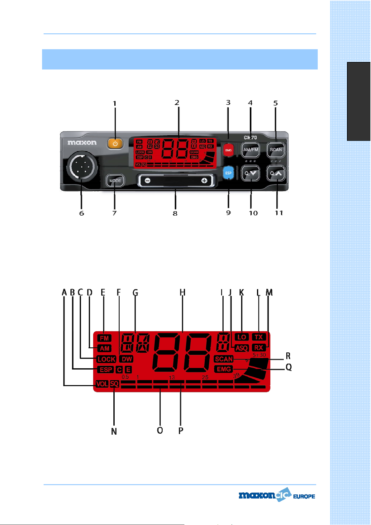
C. Symbol LOCK (Blokada kanaáów)
Symbol LOCK pojawia siĊ po wáączeniu blokady przeáączania kanaáów.
D. Symbol AM
Symbol AM pojawia siĊ, gdy radiotelefon CB nadaje i odbiera sygnaá z modulacją AM.
E. Symbol FM
Symbol FM pojawia siĊ, gdy radiotelefon CB nadaje i odbiera sygnaá z modulacją FM.
F. Symbol DW (Automatyczne monitorowanie dwóch kanaáów)
Symbol DW pojawia siĊ po wáączeniu funkcji DUAL WATCH (Automatyczne monitorowanie dwóch kanaáów).
Funkcja DW (Dual Watch) pozwala automatycznie monitorowaü dwa zaprogramowane kanaáy. Wybierz
pierwszy kanaá do nasáuchu za pomocą przycisków
Aby wáączyü funkcjĊ monitorowania dwóch kanaáów, wciĞnij i przytrzymaj przycisk EMG, aĪ pojawi siĊ i
zacznie migaü symbol DW na wyĞwietlaczu. NastĊpnie wybierz drugi kanaá do nasáuchu za pomocą
przycisków
Funkcja automatycznego monitorowania dwóch kanaáów zostaáa uruchomiona i na wyĞwietlaczu bĊdą na
przemian pojawiaáy siĊ numery obu wybranych kanaáów. Na wyĞwietlaczu pojawi siĊ teĪ symbol DW.
Monitorowanie zostanie wstrzymane po pojawieniu siĊ sygnaáu w którymĞ z dwóch nasáuchiwanych kanaáów,
tak aby uĪytkownik mógá wysáuchaü
przywrócone po stwierdzeniu zaniku sygnaáu w tym kanale. Wciskając przycisk PTT moĪna nadawaü na tym
kanale. W przypadku braku sygnaáu przez 5 sekund, monitorowanie zostanie przywrócone. Aby wyáączyü
funkcjĊ monitorowania dwóch kanaáów, wciĞnij na chwilĊ przycisk PTT.
G. H. I. WyĞwietlacz alfanumeryczny
G. Te dwa znaki przekazują informacjĊ o kodzie kraju zgodnie z zaprogramowanym pasmem czĊstotliwoĞci
(np. DE, UK, CE, itd.).
H. I. Te dwa znaki przekazują informacjĊ o numerze kanaáu roboczego (01 do 80 zgodnie z
zaprogramowanym pasmem czĊstotliwo
J. Symbol ASQ (Automatyczna blokada szumów)
Symbol ASQ pojawia siĊ po wáączeniu automatycznej blokady szumu.
lub przycisków wybierania kanaáów na mikrofonie. WciĞnij i przytrzymaj przycisk EMG.
rozmowy prowadzonej w tym kanale. Monitorowanie zostanie
Ğci), jeĞli wáączono funkcjĊ wyĞwietlania numeru kanaáu
lub przycisków wybierania kanaáów na mikrofonie.
Polski
K. Symbol LO (Nadawanie z maáą mocą)
Symbol LO pojawia siĊ po wáączeniu nadawania z maáą mocą (1 W).
L. Symbol TX (Nadawanie)
Symbol TX pojawia siĊ, gdy urządzenie jest przeáączone w tryb nadawania.
M. Symbol RX (Odbiór)
Symbol RX pojawia siĊ, gdy urządzenie jest przeáączone w tryb odbioru.
N. Symbol SQ (Blokada szumu)
Symbol SQ pojawia siĊ podczas regulacji blokady szumu.
O. Cyfrowy wskaĨnik poziomu gáoĞnoĞci i blokady szumu
Cyfrowy 10-segmentowy cyfrowy wskaĨnik poziomu gáoĞnoĞci i blokady szumu.
P. Cyfrowy wskaĨnik poziomu nadawania i odbioru
Cyfrowy 10-segmentowy cyfrowy wskaĨnik mocy odbieranego sygnaáu (od S0 do S9+30) w trybie odbioru i
mocy nadawanego sygnaáu (0 do 4 W) w trybie nadawania.
Q. Symbol EMG (Kanaá ratunkowy)
Symbol EMG pojawia siĊ po wybraniu jednego z zaprogramowanych kanaáów ratunkowych.
R. Symbol SCAN (Przeglądanie kanaáów)
Symbol SCAN pojawia siĊ po wáączeniu funkcji automatycznego przeglą
3. Przycisk EMG (Kanaáy ratunkowe)
Page 54 of 68
dania aktywnych kanaáów.
F
F
F
u
u
u
n
n
n
k
k
k
c
c
c
j
j
j
e
e
e
i
i
i
e
e
e
l
l
l
e
e
e
m
m
m
e
e
e
n
n
n
t
t
t
y
y
y
s
s
s
t
t
t
e
e
e
r
r
r
o
o
o
w
w
w
a
a
a
n
n
n
i
i
i
a
a
a
Page 16

User Manual CM70
Funkcje i elementy sterowania
Panel przedni
Polski
1. Przycisk Wà/WYà
Przycisk wáącza i wyáącza radiotelefon CB
2. Wielofunkcyjny wyĞwietlacz
DuĪy podĞwietlany na czerwono wyĞwietlacz zapewnia czytelnoĞü informacji. Na wyĞwietlaczu pojawiają siĊ
opisy wszystkich uruchomionych funkcji oraz kilka innych informacji (programowanych przez uĪytkownika),
takich jak: numer kanaáu lub peány 5-znakowy zapis czĊstotliwoĞci. 10-segmentowy wskaĨnik informuje o
poziomie nadawanego i odbieranego sygnaáu.
.
F
F
F
u
u
u
n
n
n
k
k
k
c
c
c
j
j
j
e
e
e
i
i
i
e
e
e
l
l
l
e
e
e
m
m
m
e
e
e
n
n
n
t
t
t
y
y
y
A. Symbol VOL (GáoĞnoĞü)
Symbol VOL (gáoĞnoĞü) pojawia siĊ podczas zmiany poziomu gáoĞnoĞci dĨwiĊku.
B. Symbol ESP C E
Symbol ESP pojawia siĊ po wáączeniu funkcji ESP (Elektroniczne przetwarzanie mowy).
Page 53 of 68
s
s
s
t
t
t
e
e
e
r
r
r
o
o
o
w
w
w
a
a
a
n
n
n
i
i
i
a
a
a
Page 17

User Manual CM70
q
r
P
r
Dane techniczne
Ogólne
IloĞü kanaáów………………………………………..………...……………………………...…....40 AM/FM 4W
Zakres czĊstotliwoĞci….………………………………….………….…...…………..…65 do 27,99125 MHz
Kontrola czĊstotliwoĞci……………………………………………….………..…………………tla fazowa PLL
Polski
Temperatura pracy…………………………………………..……..……..………..………………-10
Zasilanie……………………...…………………………..…………...……….............13,2 V prąd staáy
Wymiary zewnĊtrzne………….……………………………………182 (dá.) X 37 (wys.) X 139 (gá.) mm
Waga…………………………………………………………………..……..…………………...………………850 g
Odbiornik
System odbioru………………………………Superheterodyna z podwójną przemianą czĊstotliwoĞci
CzĊstotliwoĞci poĞrednie…………………..……..……..……………….…….……10,695 MHz i 455 MHZ
CzuáoĞü…………………………………..……..……..……………..…………0.5
Znieksztaácenia akustyczne…………………………………………………………………< 8% przy 1 KHz
Táumienie czĊstotliwoĞci lustrzanej………………………………………………………………………..65dB
Separacja kanaáów………….………………………………………..…………………………………………65dB
OdstĊp sygnaá/szum…………………………………………………..……………………………………….45dB
Pobór prądu podczas czuwania…………………………………..……………….……………………250 mA
V przy 20 db SINAD w FM
/ +55qC
15%
Pobór prądu przy maksymalnym poziomie wzmocnienia…….……………………………………650 mA
Nadajnik
Moc wyjĞciowa…………………………………………………………..……...4W przy 13.2 V prądu staáego
Modulacja………………………………………..………………..……………………...…FM: 1,8 KHz
Pasmo przenoszenia……………………..…..………………..…….………………..……..400 Hz do 2,5 KHz
Impedancja wyjĞciowa………………………………………...……………RF 50 Ohm niezrównowaĪona
OdstĊp sygnaá/szum……………………………………………………………….………………… min. 40 dB
Pobór prądu…………………………………………………………..………………………….…………1200 mA
Page 52 of 68
0,2 KHz
D
D
D
a
a
a
n
n
n
e
e
e
t
t
t
e
e
e
c
c
c
h
h
h
n
n
n
i
i
i
c
c
c
z
z
z
n
n
n
e
e
e
Page 18

User Manual CM70
Spis treĞci
Dane techniczne ..........................................................................................................42
Funkcje i elementy sterowania ......................................................................................42
Mikrofon Dane .............................................................................................................42
Instalacja ....................................................................................................................42
Instalacja radiotelefonu CB ...........................................................................................42
Instalacja anteny .........................................................................................................42
Sprawdzenie dziaáania ..................................................................................................42
Tabela czĊstotliwoĞci ....................................................................................................42
Wybieranie przedziaáu czĊstotliwoĞci ..............................................................................42
Ograniczenia korzystania z radiotelefonów CB w Europie .................................................61
Aktualne informacje o ograniczeniach korzystania z radiotelefonów CB .............................62
Schematy ............................................................................................................... 63-67
Deklaracja zgodnoĞci ....................................................................................................68
Polski
Page 51 of 68
S
S
S
p
p
p
i
i
i
s
s
s
t
t
t
r
r
r
e
e
e
s
s
s
c
c
c
i
i
i
Page 19

User Manual CM70
Tabella delle bande di frequenza
Il ricetrasmettitore CM70 include un circuito programmabile multi-standard avanzato, che consente di
programmare su bande di frequenza, parametri e modalità operative diversi, in conformità alle normative
vigenti nel paese in cui viene utilizzato il prodotto. Sono disponibili 10 bande di frequenza programmabili,
come indicato dalla tabella seguente:
CODICE
PAESE
I0 ITALIA 40 CH AM / FM 4 W
I2 ITALIA 36 CH AM / FM 4 W
DE GERMANIA 80 CH FM 4 W - 12 CH AM 1 W
D2 GERMANIA 40 CH FM 4 W - 12 CH AM 1 W
EU EUROPA 40 CH FM 4 W - 40 CH AM 1 W
CE CEPT 40 CH FM 4 W
SP SPAGNA 40 CH AM / FM 4 W
FR FRANCIA 40 CH FM 4 W - 40 CH AM 1 W
UK REGNO UNITO
PL POLONIA 40 CH AM /
Attenzione! Questa radio è stata pre-programmata in origine sulla banda di frequenza EC (CEPT 40 CH
FM 4 W), poiché questo standard è attualmente accettato in tutti i paesi europei. Consultare la tabella
informativa (Restrizioni sull'uso dei ricetrasmettitori CB).
PAESE
SPECIFICHE (CH, modalità operative,
potenza TX)
40 CH FM 4W FREQUENZE REGNO UNITO - 40
CH FM 4W FREQUENZE CEPT
FM 4 W FREQUENZE
POLACCHE
Programmazione/selezione della banda di
frequenza
Questa radio deve essere programmata e utilizzata esclusivamente su una banda di frequenza consentita nel
paese in cui viene impiegata. Per programmare una banda di frequenza differente, procedere come indicato
di seguito:
1) Spegnere la radio.
2) Premere e mantenere premuto il tasto EMG mentre si riaccende la radio ruotando l'apposita
manopola. Rilasciare il pulsante quando tutte le icone visualizzate sono ancora accese.
3) Il codice paese corrente lampeggia sul display LCD (2 cifre).
4) Selezionare il nuovo codice paese desiderato mediante i tasti
5) Premere brevemente il tasto EMG per confermare.
jo i.
Italiano
Page 50 of 68
Page 20

User Manual CM70
Montaggio
È opportuno individuare la posizione più comoda per il montaggio dell'unità nel veicolo, in modo che la radio
sia facile da raggiungere e da utilizzare durante la guida. Per montare la radio utilizzare la staffa e i materiali
forniti. Le viti della staffa devono essere adeguatamente fissate in modo che non si allentino a causa delle
vibrazioni del veicolo. È possibile montare la staffa di supporto per auto al di sopra o al di sotto della radio,
che può essere inclinata in base alle necessità secondo il tipo di montaggio specifico (sotto il cruscotto o il
tettuccio della cabina).
Montaggio dell'unità principale
Prima di collegare la radio al sistema elettrico del veicolo, assicurarsi che la radio sia spenta. Il cavo di
alimentazione CC della radio è dotato di un portafusibile e il fusibile è posizionato sul cavo rosso positivo (+).
Collegare il cavo di alimentazione CC al sistema elettrico del veicolo, facendo attenzione alla polarità, anche
se la radio è comunque protetta dall'inversione di polarità. Collegare il cavo rosso al polo positivo (+) e il
cavo nero al polo negativo (-) del sistema elettrico del veicolo. Assicurarsi che i cavi e i terminali siano
saldamente collegati in modo da evitare scollegamenti o cortocircuiti.
Installazione dell'antenna
È necessario utilizzare un'antenna mobile specifica regolata sulla gamma di frequenza 27 MHz. Il montaggio
dell'antenna deve essere effettuato da un tecnico specializzato o in un centro di assistenza. È necessario
prestare particolare attenzione in modo che l'antenna sia montata sul veicolo con una perfetta messa a
terra. Prima di collegare l'antenna alla radio, è necessario verificare, mediante appositi strumenti,
l'operatività corretta dell'antenna con un basso rapporto d'onda stazionaria (ROS). In caso contrario, il
circuito del trasmettitore potrebbe danneggiarsi. L'antenna deve essere montata sulla parte più alta del
veicolo, libera da ostacoli e il più lontano possibile da fonti di rumore elettrico o elettromagnetico. Prestare
attenzione a non danneggiare o schiacciare il cavo coassiale dell'antenna RF nel percorso tra l'antenna e la
radio. È necessario controllare periodicamente la corretta operatività dell'antenna e il basso rapporto d'onda
stazionaria (ROS). Collegare il cavo coassiale dell'antenna RF al connettore dell'antenna situato sulla parte
posteriore della radio.
Test di operatività
Italiano
Una volta collegata la radio al sistema di alimentazione del veicolo e installata l'antenna, è possibile
procedere con la verifica del funzionamento del sistema. Procedere come segue:
33.) Verificare che l'unità sia installata correttamente.
34.) Verificare che il cavo di alimentazione sia collegato correttamente.
35.) Verificare che il connettore coassiale dell'antenna RF sia collegato correttamente.
36.) Collegare il microfono alla presa posta sul pannello anteriore.
37.) Accendere l'unità e selezionare la banda di frequenza corretta in base al paese in cui ci si trova
(vedere a pagina 10).
38.) Regolare lo squelch in modo che sia aperto (rumorosità da diffusore) mediante il tasto MODE,
selezionare SQ e utilizzare i tasti
39.) Selezionare il canale desiderato mediante i tasti
40.) Premere il tasto PTT (Push-to-Talk) per trasmettere e rilasciarlo per ricevere.
Se il test dà risultati soddisfacenti, l'unità è pronta per essere utilizzata. In caso di problemi, contattare il
rivenditore.
j o i.
j o i.
Page 49 of 68
Page 21

User Manual CM70
MICROFONO
1916 17 18
Italiano
20
16. Tasto PTT (Push-to-Talk)
Tasto trasmettitore. Premere il tasto PTT per trasmettere e rilasciarlo per ritornare in modalità di ricezione.
17. Tasto UP (selettore canale)
Ogni volta che il tasto viene premuto, il numero di canale incrementa di uno.
* Utilizzabile al posto di
18. Tasto LOCK/MODE
La funzione LOCK viene abilitata mediante la pressione di questo tasto e consente di bloccare la tastiera per
evitare l'attivazione involontaria di funzioni indesiderate. Quando la funzione LOCK è abilitata, l'icona LOCK è
visibile sul display LCD.
Questo tasto può essere utilizzato per impostare le funzioni ASQ, SQ, SEGNALE ACUSTICO,
RETROILLUMINAZIONE e MEMORIA. Questo tasto corrisponde al tasto MODE posto sul lato anteriore della
radio.
* Utilizzare questo tasto anche per incrementare o ridurre il livello del volume.
Premere ripetutamente il tasto LOCK/MODE fino a quando sul display LCD non viene visualizzata l'icona
o . Per incrementare e ridurre il livello del volume dal microfono, è anche possibile utilizzare i
tasti UP e DOWN.
19. Tasto DOWN (selettore canale)
Ogni volta che il tasto viene premuto, il numero di canale diminuisce di uno.
* Utilizzabile al posto di
20. Presa MICROFONO
Il connettore del microfono a 6 poli (con ghiera di bloccaggio) consente di collegare il microfono alla presa
del microfono sul pannello frontale della radio.
Page 48 of 68
i
j
C
C
C
o
o
o
m
m
m
a
a
a
n
n
n
d
d
d
i
i
i
e
e
e
o
o
o
p
p
p
e
e
e
r
r
r
a
a
a
t
t
t
i
i
i
v
v
v
i
i
i
t
t
t
à
à
à
Page 22

User Manual CM70
13. Jack S-METER
Questo jack consente il collegamento di un dispositivo S-METER esterno (facoltativo).
14. Presa ANTENNA
Presa per antenna. Consultare la sezione INSTALLAZIONE DELL'ANTENNA.
15. CAVO ALIMENTAZIONE 13.8 CC
Ingresso cavo alimentazione 13.8 CC.
Italiano
Page 47 of 68
Page 23

User Manual CM70
relativi al canale vengono memorizzati (numero canale, lettura frequenza, modalità AM/FM, potenza
trasmissione, ecc.).
RICHIAMO DEI CANALI MEMORIZZATI
Premere/mantenere premuto il tasto MODE per visualizzare il numero del canale in memoria (M0-M9).
Utilizzare il tasto
per uscire dalla modalità di richiamo dei canali in memoria.
8. Barra di scorrimento Su - Giù
Utilizzare i comandi
9. Tasto ESP (Electronic Speech Processor)
La sofisticata funzione ESP (Electronic Speech Processor) è un'esclusiva della radio CB Maxon CM70. La
tecnologia ESP (Electronic Speech Processor) funge da compressore della modulazione durante la
trasmissione e da espansore della modulazione durante la ricezione. Grazie alla funzionalità ESP, è possibile
ottenere segnali audio più puliti e più chiari, in particolare in aree particolarmente disturbate e in caso di
comunicazioni a lunga distanza o segnali deboli. L'efficacia della funzione ESP è ancora maggiore se si
comunica con altre radio che utilizzano lo stesso sistema. Per abilitare o disabilitare
la funzione ESP, premere il tasto ESP. Se la funzione è abilitata, l'icona ESP è visibile sul display LCD.
Prestazioni ESP
della modulazione
in modalità RX e TX
j o i per selezionare il canale memorizzato desiderato. Premere di nuovo il tasto MODE
e per incrementare o ridurre il livello di volume e squelch.
Italiano
10. Tasto
Questo tasto consente la selezione rapida del canale operativo successivo. Ogni volta che il tasto viene
premuto, il numero di canale diminuisce di uno. Premere il tasto per circa 2 secondi per spostare il numero
di canale indietro di 10 posizioni.
11. Tasto
Questo tasto consente la selezione rapida del canale operativo in ordine crescente. Ogni volta che il tasto
viene premuto, il numero di canale incrementa di uno. Premere/mantenere premuto il tasto per per spostare
il numero di canale avanti di 10 posizioni.
Pannello posteriore
j (rapido giù)
i
(rapido su)
C
C
C
o
o
o
m
m
m
a
a
a
n
n
n
d
d
d
i
i
i
e
e
e
12. Jack diffusore EXT (esterno)
Questo jack consente il collegamento di un diffusore esterno (facoltativo).
Page 46 of 68
o
o
o
p
p
p
e
e
e
r
r
r
a
a
a
t
t
t
i
i
i
v
v
v
i
i
i
t
t
t
à
à
à
Page 24

User Manual CM70
canale operativo normale. Quando viene selezionato uno dei due canali di emergenza, sul display LCD
apparirà l'icona EMG (emergenza). La modalità operativa (AM o FM) per i canali di emergenza è preprogrammata come settaggio di fabbrica, in base alla tabella seguente.
CODICE PAESE I0 I2 DE D2 EU CE SP FR UK PL
CH-9 AM AM AM AM AM FM AM AM FM AM
CH-19 AM AM AM AM AM FM AM AM FM AM
4. Tasto AM/FM
Questo tasto consente all'utente di selezionare la modalità AM o FM sia in RX che in TX. È possibile
selezionare la modalità AM/FM solo se questa è consentita nella banda di frequenza programmata.
5. Tasto SCAN
Premendo il tasto SCAN, viene abilitata la funzione SCAN (scansione automatica dei canali occupati). Per
abilitare la funzione SCAN, regolare prima il livello di SQUELCH fino a eliminare completamente il rumore di
fondo. Quindi premere il tasto SCAN; la radio inizierà automaticamente la scansione continua di tutti i canali
e sul display LCD verrà visualizzata l'icona SCAN. La scansione automatica viene interrotta al rilevamento di
un segnale su un canale (per consentire all'utente di ascoltare il segnale in entrata) e viene ripresa quando
non viene rilevato più alcun segnale su tale canale. Se il pulsante PTT viene premuto entro 5 secondi, la
radio rimane su tale canale; in caso contrario, la scansione riprende. La scansione automatica può essere
riavviata in qualsiasi momento mediante la pressione del tasto SCAN. Per uscire dalla modalità SCAN,
premere brevemente il pulsante PTT.
6. Presa MICROFONO
Collegare il microfono dinamico fornito in dotazione a questa presa e fissarlo mediante la ghiera di
bloccaggio.
7. Tasto MODE
Utilizzare il tasto MODE per abilitare e programmare le varie funzioni della radio. Se si preme il tasto MODE
vengono fatte scorrere tutte le varie funzioni. La sequenza varia in base alle funzioni correnti selezionate.
- Comando ASQ (squelch automatico)
Per abilitare il comando ASQ, premere ripetutamente il tasto MODE fino a quando sul display LCD non viene
visualizzata l'icona
premere brevemente il tasto PTT per confermare e memorizzare l'impostazione.
o . Utilizzare il tasto j o i per impostare il livello desiderato, quindi
Italiano
- LIVELLO SQUELCH
Per regolare il livello di squelch, premere ripetutamente il tasto MODE fino a quando sul display LCD non
viene visualizzata l'icona
- SEGNALE ACUSTICO
Ogni volta che viene premuto un tasto, viene emesso un segnale acustico per confermare la selezione del
comando. Per abilitare o disabilitare tale segnale acustico, premere ripetutamente il tasto MODE fino a
quando sul display LCD non viene visualizzata l'icona
impostare il livello desiderato, quindi premere brevemente il tasto PTT per confermare e memorizzare
l'impostazione.
- IMPOSTAZIONE RETROILLUMINAZIONE DISPLAY LCD
Premere ripetutamente il tasto MODE fino a quando sul display LCD non viene visualizzata l'icona
. Utilizzare il tasto j o i per impostare il livello desiderato, quindi premere brevemente il tasto PTT
per confermare e memorizzare l'impostazione.
PROGRAMMAZIONE DEI CANALI IN MEMORIA (M0-M9)
Utilizzare il tasto
quando sul display LCD non viene visualizzata l'icona
selezionare un numero di canale da memorizzare, quindi premere e mantenere premuto il tasto MODE fino a
quando il numero di canale precedentemente selezionato non viene visualizzato sul display LCD. Tutti i dati
Page 45 of 68
j o i per selezionare il canale da memorizzare. Premere varie volte il tasto MODE fino a
. Utilizzare i tasti e per incrementare o ridurre il livello di squelch.
o . Utilizzare il tasto j o i per
o
(M0-M9). Utilizzare il tasto j o i per
C
C
C
o
o
o
m
m
m
a
a
a
n
n
n
d
d
d
i
i
i
e
e
e
o
o
o
p
p
p
e
e
e
r
r
r
a
a
a
t
t
t
i
i
i
v
v
v
i
i
i
t
t
t
à
à
à
Page 25

User Manual CM70
C. Icona LOCK
L'icona LOCK è visibile quando viene attivata la funzione di blocco.
D. Icona AM
L'icona AM è visibile quando la radio riceve e trasmette in modalità AM (onde medie).
E. Icona FM
L'icona FM è visibile quando la radio riceve e trasmette in modalità FM (modulazione di frequenza).
F. Icona DW
L'icona DW è visibile quando la funzione DUAL WATCH (monitoraggio automatico di due canali) è abilitata.
La funzione DW (Dual Watch) consente il monitoraggio automatico alternato di due canali programmabili.
Selezionare il primo canale da monitorare mediante i pulsanti
sul microfono. Per abilitare la funzione DW, premere e tenere premuto il tasto EMG fino a quando l'icona DW
non inizia a lampeggiare sul display LCD. Selezionare quindi il secondo canale da monitorare mediante i
pulsanti
EMG. La funzione DW è abilitata e sul display LCD vengono alternativamente visualizzati i numeri dei due
canali programmati. L'icona DW è visibile sul display LCD. Se viene rilevato un segnale su uno dei due canali,
il monitoraggio viene interrotto per consentire all'utente di ascoltare il segnale in entrata, quindi viene
ripreso quando non viene rilevato più alcun segnale su tale canale. Per trasmettere su tale canale è
sufficiente premere il tasto PTT. Se non viene effettuata alcuna trasmissione entro 5 secondi, il monitoraggio
inizia di nuovo. Per uscire dalla modalità DW, premere brevemente il pulsante PTT.
j e i o i tasti di selezione dei canali presenti sul microfono. Premere e mantenere premuto il tasto
j e i o i tasti di selezione dei canali presenti
Italiano
G. H. I. Cifre alfanumeriche
G. Queste due cifre alfanumeriche indicano il codice del paese, in base alla banda di frequenza programmata
(ad es. DE, UK, CE, ecc.).
H. I. Queste tre cifre alfanumeriche indicano il numero del canale operativo (da 01 a 80, in base alla banda
di frequenza programmata), quando la funzione di lettura del numero di canale è abilitata.
J. Icona ASQ
L'icona ASQ è visibile quando è abilitata la funzione Auto Squelch (silenziatore automatico).
K. Icona LO
L'icona LO è visibile quando il trasmettitore è in modalità LOW POWER (bassa potenza) (1 W).
L. Icona TX
L'icona TX è visibile quando la radio è in modalità di trasmissione.
M. Icona RX
L'icona RX è visibile quando la radio è in modalità di ricezione.
N. Icona SQ
L'icona SQ è visibile durante la regolazione del comando SQUELCH (silenziatore).
O. Icona livello digitale VOLUME/SQUELCH
Indicatore digitale a 10 barre che riporta il livello del volume e dello squelch.
P. Indicatore digitale S/RF
Indicatore digitale a 10 barre che riporta la potenza del segnale ricevuto (da S0 a S9+30) in modalità di
ricezione e la potenza RF in uscita del trasmettitore (da 0 a 4 W) in modalità di trasmissione.
Q. Icona EMG
L'icona EMG è visibile quando viene selezionato uno dei canali di emergenza pre-programmati.
C
C
C
o
o
o
m
m
m
a
a
a
n
n
n
d
d
d
i
i
i
e
e
e
R. Icona SCAN
L'icona SCAN è visibile quando la funzione SCAN (ricerca automatica dei canali occupati) è abilitata.
3. Tasto EMG (canali di emergenza)
Questo tasto consente di accedere rapidamente a uno dei due canali di emergenza pre-programmati (CH9 e
CH19). Ogni volta che si preme questo tasto, la radio selezionerà CH9, quindi CH19 e successivamente il
Page 44 of 68
o
o
o
p
p
p
e
e
e
r
r
r
a
a
a
t
t
t
i
i
i
v
v
v
i
i
i
t
t
t
à
à
à
Page 26
User Manual CM70
Comandi e operatività
Pannello frontale
Italiano
1. Accensione/Spegnimento
Utilizzare questa manopola per ACCENDERE o SPEGNERE la radio
2. Display LCD
L'ampio display retroilluminato in rosso garantisce una perfetta leggibilità. Sul display LCD sono visualizzate
tutte le funzioni abilitate oltre a numerose altre funzioni (programmabili dall'utente), quali lettura del canale
o lettura della frequenza completa a 5 cifre. Il display include inoltre un indicatore digitale S/RF a 10 barre
per monitorare la potenza dei segnali ricevuti e trasmessi.
.
C
C
C
o
o
o
m
m
m
a
a
a
n
n
n
d
d
d
i
i
i
e
e
e
A. Icona VOL
L'icona VOL è visibile quando vengono effettuate delle regolazioni del volume.
B. Icona ESP C E
L'icona ESP è visibile quando la funzione ESP (Electronic Speech Processor) è abilitata.
Page 43 of 68
o
o
o
p
p
p
e
e
e
r
r
r
a
a
a
t
t
t
i
i
i
v
v
v
i
i
i
t
t
t
à
à
à
Page 27

User Manual CM70
Specifiche
Generale
Canali………………………………………..………...……………………………......…....40 Ch AM/FM 4 W
Gamma di frequenza……………………………………………………………....da 26.565 a 27.99125 MHz
Controllo della frequenza………………………………………………………………………………………PLL
Intervallo di temperatura operativa……………………………………………..………….….-10
Voltaggio in ingresso CC…………………………...…………………...……………………13,2 V CC
Dimensioni……………………………….…………………………180 (larg.) X 37 (alt.) X 139 (prof.) mm
Peso……………………………………………………………………………………………………..……0,850 kg
Ricevitore
Sistema di ricezione………………………………………………….Supereterodina a doppia conversione
°
Frequenza intermedia……………………………………………….1
Sensibilità…………………………………………………………….0,5
Distorsione audio……………………………………………………………………Inferiore all'8% @ 1 KHz
Reiezione immagine…………………………………………………………………………………………65 dB
Reiezione immagine adiacente……………………………………………………………………………65 dB
FI: 10,695 MHz, 2° FI: 455 MHz
PV per 20 db SINAD in modalità FM
q / +55qC
r 15%
Italiano
Rapporto segnale/ rumore………………………………………………………………………………45 dB
Consumo di corrente in standby..……………………………………………………………………250 mA
Consumo di corrente con l'audio al massimo…………………………………………………650 mA
Trasmettitore
Potenza in uscita…………………………………………………………………………………4 W @ 13,2 V CC
Modulazione…………………………………………………………………………………FM: 1,8 KHz
Risposta in frequenza………………………………………………………………………Da 400 Hz a 2,5 KHz
Impedenza di uscita…………………………………………………………………RF 50 ohm non bilanciata
Rapporto segnale/ rumore……………………………………………………………………………40 dB MIN
Consumo di corrente………………………………………………………………………………………1200 mA
Page 42 of 68
r0,2 KHz
S
S
S
p
p
p
e
e
e
c
c
c
i
i
i
f
f
f
i
i
i
c
c
c
h
h
h
e
e
e
Page 28

User Manual CM70
Sommario
Specifiche ....................................................................................................................42
Comandi e operatività .................................................................................................4-8
Microfono ...................................................................................................................48
Installazione ................................................................................................................49
Installazione dell'unità principale ...................................................................................49
Installazione dell'antenna .............................................................................................49
Test di operatività ........................................................................................................49
Tabella delle bande di frequenza ...................................................................................50
Selezione delle bande di frequenza.................................................................................50
Italiano
Tabella delle limitazioni ................................................................................................61
Informazioni aggiornate sulle restrizioni nazionali ...........................................................62
Schemi ................................................................................................................... 63-67
Dichiarazione di conformità ...........................................................................................68
Page 41 of 68
S
S
S
o
o
o
m
m
m
m
m
m
a
a
a
r
r
r
i
i
i
o
o
o
Page 29

User Manual CM70
Frequenzbandtabelle
Der CM70-Transceiver verfügt über eine fortgeschrittene Multistandard-Schaltung, die eine Programmierung
des Funkgeräts in Bezug auf verschiedene Frequenzbänder, Spezifikationen und Betriebsarten ermöglicht (in
Übereinstimmung mit den Vorschriften des Landes, in dem das Produkt verwendet wird). Es sind 10
verschiedene Frequenzbänder verfügbar, die in der folgenden Tabelle aufgeführt sind:
LÄNDERCODE
I0 ITALIEN 40 Kanäle AM / FM 4 W
I2 ITALIEN 36 Kanäle AM / FM 4 W
DE
D2
EU EUROPA 40 Kanäle FM 4 W - 40 Kanäle AM 1 W
CE CEPT-LÄNDER 40 Kanäle FM 4 W
SP SPANIEN 40 Kanäle AM / FM 4 W
FR FRANKREICH 40 Kanäle FM 4 W - 40 Kanäle AM 1 W
GB
PL POLEN 40 Kanäle AM
Achtung! Ab Werk ist dieses Funkgerät auf das CE-Frequenzband (CEPT, 40 Kanäle, FM, 4 W)
vorprogrammiert, da diese Einstellung zurzeit in allen europäischen Ländern zugelassen ist. Näheres finden
Sie in der Tabelle (Einschränkungen beim Betrieb von CB-Funkgeräten in einzelnen Ländern).
Frequenzbandauswahl/Programmierung
LAND
DEUTSCHLAN
D
DEUTSCHLAN
D
GROSSBRITAN
NIEN
SPEZIFIKATIONEN (Kanäle,
Betriebsarten, Sendeleistung)
80 Kanäle FM 4 W - 12 Kanäle AM 1 W
40 Kanäle FM 4 W - 12 Kanäle AM 1 W
40 Kanäle FM 4 W GB-FREQUENZEN - 40 Kanäle
FM 4 W CEPT-FREQUENZEN
/ FM 4 W POLNISCHE
FREQUENZEN
Deutsch
Bei diesem Funkgerät darf nur ein Frequenzband eingestellt und verwendet werden, das in dem Land
zugelassen ist, in dem das Produkt eingesetzt wird. Um die Frequenzbandeinstellung zu ändern, gehen Sie
wie folgt vor:
1) Schalten Sie das Funkgerät aus.
2) Drücken und halten Sie die EMG-Taste gedrückt, während Sie das Funkgerät mit dem Ein/Aus-Knopf
einschalten. Lassen Sie die Taste los, während alle angezeigten Symbole noch aufleuchten.
3) Der aktuelle Ländercode blinkt jetzt am LCD-Display (zwei Stellen).
4) Wählen Sie jetzt mit j oder i den gewünschten neuen Ländercode.
5) Drücken Sie kurz die EMG-Taste zur Bestätigung.
Page 40 of 68
F
F
F
r
r
r
e
e
e
q
q
q
u
u
u
e
e
e
n
n
n
z
z
z
b
b
b
a
a
a
n
n
n
d
d
d
t
t
t
a
a
a
b
b
b
e
e
e
l
l
l
l
l
l
e
e
e
Page 30

User Manual CM70
j
j
Installation
Suchen Sie vor dem Einbau des Hauptgeräts im Fahrzeug zuerst den besten Einbauort, damit das Funkgerät
gut zugänglich und leicht zu bedienen ist, aber trotzdem kein Sicherheitsrisiko für Fahrer und Beifahrer
darstellt. Benutzen Sie die mitgelieferte Halterung und das Montagematerial für den Einbau des Funkgeräts.
Die Schrauben der Halterung müssen fest angezogen werden, damit sie sich durch die Vibrationen während
der Fahrt nicht lockern können. Die Kfz-Montagehalterung kann über oder unter dem Funkgerät befestigt
werden, und das Funkgerät kann auch je nach Installationsart (unter dem Armaturenbrett oder am
Führerhausdach des LKW) wie gewünscht gekippt werden.
Installation des Hauptgeräts
Bevor Sie das Funkgerät an das Kfz-Bordnetz anschließen, stellen Sie sicher, dass das Funkgerät
ausgeschaltet ist. Das Gleichstromkabel ist mit einem Sicherungshalter ausgestattet (Sicherung befindet sich
am roten Plusdraht (+)). Schließen Sie das Gleichstromkabel an das Kfz-Bordnetz an, und achten Sie dabei
unbedingt auf die korrekte Polarität, selbst wenn das Funkgerät gegen eine mögliche Verpolung geschützt
ist. Schließen Sie den roten Draht an den Pluspol (+) und den schwarzen Draht an den Minuspol (-) des KfzBordnetzes an. Überprüfen Sie die Geräte und Anschlüsse auf festen Sitz und guten Kontakt, damit sich die
Kabel nicht lösen und Kurzschlüsse verursachen können.
Installation der Antenne
Verwenden Sie ausschließlich eine mobile Antenne, die auf den 27-MHz-Frequenzbereich abgestimmt ist. Die
Antenneninstallation muss von einem Fachmann oder in einer Fachwerkstatt durchgeführt werden. Bitte
achten Sie besonders darauf, dass die Antenne vollständig auf dem Fahrzeug installiert wird und über eine
einwandfreie Masseverbindung verfügt. Überprüfen Sie vor dem Anschluss der Antenne an das Funkgerät
unter Verwendung geeigneter Messgeräte, ob die Antenne ordnungsgemäß funktioniert und das korrekte
Stehwellenverhältnis (SWR) aufweist. Andernfalls kann die Sendeschaltung des Funkgeräts beschädigt
werden. Die Antenne wird normalerweise am höchsten Punkt des Fahrzeugs installiert, an dem der Empfang
nicht behindert wird, möglichst weit entfernt von elektrischen oder elektromagnetischen Rauschquellen. Das
HF-Koaxialkabel der Antenne darf nicht beschädigt sein, und es darf nicht zwischen Antenne und Funkgerät
eingeklemmt werden. Die Funktionsfähigkeit der Antenne und das Stehwellenverhältnis (SWR) müssen in
regelmäßigen Abständen überprüft werden. Schließen Sie das HF-Koaxialkabel der Antenne an die
Antennenbuchse auf der Rückseite des Funkgeräts an.
Deutsch
Funktionsprüfung
Wenn das Funkgerät an das Kfz-Bordnetz angeschlossen und die Antenne installiert wurde, kann die
korrekte Funktion des Systems überprüft werden. Gehen Sie bitte wie folgt vor:
Stellen Sie sicher, dass das Gerät korrekt installiert wurde.
Prüfen Sie, ob das Stromkabel richtig angeschlossen ist.
Prüfen Sie, ob das HF-Koaxialkabel der Antenne richtig angeschlossen ist.
Schließen Sie das Mikrofon an die Buchse auf der Vorderseite an.
Schalten Sie das Gerät ein und wählen Sie das korrekte Frequenzband für das Land, in
dem es verwendet wird (siehe Seite 10).
Öffnen Sie die Rauschsperre (Hintergrundrauschen vom Lautsprecher) mit der MODE-Taste, wählen
Sie SQ (Rauschsperre) und verwenden Sie
Wählen Sie den gewünschten Kanal mit
Drücken Sie die PTT-Taste (Push-To-Talk), um zu senden, und lassen Sie sie los, um auf
Empfang zu schalten.
Wenn diese Überprüfung erfolgreich ist, ist das Gerät einsatzbereit. Wenden Sie sich bei Problemen an
Ihren Fachhändler.
Page 39 of 68
oderi.
oderi.
I
I
I
n
n
n
s
s
s
t
t
t
a
a
a
l
l
l
l
l
l
a
a
a
t
t
t
i
i
i
o
o
o
n
n
n
Page 31
User Manual CM70
j
MIKROFON
20
1916 17 18
Deutsch
16. PTT-(Push-to-Talk)-Taste
Das ist die Sendetaste. Drücken Sie die PTT-Taste, solange Sie senden (sprechen) wollen. Bei Loslassen der
Taste wird wieder in den Empfangsmodus geschaltet.
17. Aufwärts-Taste (für die Kanalwahl)
Bei jedem Drücken dieser Taste gehen Sie eine Kanalnummer nach oben.
* Kann anstelle von iverwendet werden.
18. LOCK/MODE-Taste
Durch Drücken dieser Taste wird die LOCK-Funktion aktiviert. Dadurch wird die Tastatur verriegelt und eine
versehentliche Aktivierung von Funktionen verhindert. Wenn die LOCK-Funktion aktiviert ist, erscheint das
LOCK-Symbol am LCD-Display.
Mit dieser Taste können auch die automatische Rauschsperre (ASQ), die Rauschsperre (SQ), der Piepton, die
Hintergrundbeleuchtung und die Speicherkanäle eingestellt werden. Diese Taste hat die gleiche Funktion wie
die MODE-Taste auf der Vorderseite des Funkgeräts.
* Mit dieser Taste kann auch die Lautstärke erhöht oder reduziert werden.
Drücken Sie die LOCK/MODE-Taste mehrmals, bis das Symbol
Die Aufwärts- oder Abwärts-Taste am Mikrofon kann auch zum Erhöhen oder Verringern der Lautstärke
verwendet werden.
19. Abwärts-Taste für die Kanalwahl
Bei jedem Drücken dieser Taste gehen Sie eine Kanalnummer nach unten.
* Kann anstelle von
20. Mikrofonstecker
6-poliger Mikrofonstecker mit Sicherungsring, zum Anschluss des Handmikrofons an die Mikrofonbuche auf
der Vorderseite des Funkgeräts.
Page 38 of 68
verwendet werden.
oder am LCD-Display erscheint.
S
S
S
t
t
t
e
e
e
u
u
u
e
e
e
r
r
r
u
u
u
n
n
n
g
g
g
u
u
u
n
n
n
d
d
d
B
B
B
e
e
e
d
d
d
i
i
i
e
e
e
n
n
n
u
u
u
n
n
n
g
g
g
Page 32

User Manual CM70
12. Buchse für externen Lautsprecher (EXT)
Diese Buchse dient zum Anschluss eines (optionalen) externen Lautsprechers.
13. Buchse für Signalpegelmessgerät (S-METER)
Diese Buchse dient zum Anschluss eines (optionalen) externen Signalpegelmessgeräts.
14. Antennenbuchse
Antennenbuchse - siehe Abschnitt INSTALLATION DER ANTENNE.
15. Stromanschlusskabel (13,8 V Gleichstrom)
Anschluss für Stromversorgungskabel mit 13,8 V Gleichspannung.
Deutsch
Page 37 of 68
S
S
S
t
t
t
e
e
e
u
u
u
e
e
e
r
r
r
u
u
u
n
n
n
g
g
g
u
u
u
n
n
n
d
d
d
B
B
B
e
e
e
d
d
d
i
i
i
e
e
e
n
n
n
u
u
u
n
n
n
g
g
g
Page 33

User Manual CM70
j
PROGRAMMIERUNG DER SPEICHERKANÄLE (M0 - M9)
Mit der Taste joderi können Sie den Kanal wählen, der als Speicherkanal programmiert werden soll.
Drücken Sie die MODE-Taste mehrmals, bis das Symbol
Verwenden Sie die Taste
halten Sie die MODE-Taste gedrückt, bis die zuvor gewählte Kanalnummer am LCD-Display erscheint. Es
werden alle Daten dieses Kanals gespeichert (Kanalnummer, Frequenzwert, AM/FM-Modus, Sendeleistung
usw.).
ABRUFEN VON KANÄLEN
Wenn Sie die MODE-Taste drücken und gedrückt halten, erscheint die Speicherkanalnummer (M0-M9) am
LCD-Display. Wählen Sie den gewünschten Speicherkanal mit der Taste joderi. Drücken Sie nochmals
die MODE-Taste, um den Speicherkanal-Abrufmodus zu verlassen.
8. SCHIEBEREGLER (hoch - niedrig)
Verwenden Sie
9. ESP-Taste (elektronischer Sprachprozessor)
Der elektronische Sprachprozessor (ESP) ist eine spezielle erweiterte Funktion des Maxon CM70 CBFunkgeräts. Der ESP fungiert beim Senden als Modulationskompressor und im Empfangsmodus als
Modulationsverstärker. Der ESP erzeugt stärkere, sauberere und klarere Audiosignale, was bei
Störeinflüssen, vor allem bei der Kommunikation über weite Entfernungen oder bei schwachen Signalen sehr
hilfreich ist. Die Wirkung des ESP verbessert sich noch mehr, wenn beide Funkgeräte das gleiche System
benutzen. Um die ESP-Funktion zu aktivieren oder deaktivieren, drücken Sie die ESP-Taste. Wenn die
Funktion aktiviert ist, erscheint das ESP-Symbol am LCD-Display.
und , um die Lautstärke und den Rauschpegel zu erhöhen oder zu reduzieren.
oderi, um die Nummer des zu speichernden Kanals zu wählen. Drücken und
(M0-M9) am LCD-Display erscheint.
Deutsch
ESP-Wirkung auf
die Modulation im
Empfangs- und Sendemodus
10.
j (Abwärts-) Schnelltaste
Mit dieser Taste wird der Betriebskanal schnell in Abwärtsrichtung gewählt. Bei jedem Drücken dieser Taste
gehen Sie eine Kanalnummer nach unten. Wenn diese Taste ungefähr 2 Sekunden lang gedrückt wird,
springt die Kanalnummer um jeweils 10 Kanäle nach unten.
i
(Aufwärts-) Schnelltaste
11.
Mit dieser Taste wird der Betriebskanal schnell gewählt; wobei die Kanalnummer schrittweise erhöht wird.
Bei jedem Drücken dieser Taste gehen Sie eine Kanalnummer nach oben. Wenn diese Taste gedrückt
gehalten wird, springt die Kanalnummer um jeweils 10 Kanäle nach oben.
Rückseite
Page 36 of 68
S
S
S
t
t
t
e
e
e
u
u
u
e
e
e
r
r
r
u
u
u
n
n
n
g
g
g
u
u
u
n
n
n
d
d
d
B
B
B
e
e
e
d
d
d
i
i
i
e
e
e
n
n
n
u
u
u
n
n
n
g
g
g
Page 34

User Manual CM70
j
Das SCAN-Symbol ist sichtbar, wenn die SCAN-Funktion (automatischer Suchlauf nach belegten Kanälen)
aktiviert ist.
3. EMG-Taste (Notrufkanäle)
Diese Taste ermöglicht den schnellen Zugriff auf die beiden vorprogrammierten Notrufkanäle (Kanal 9 oder
19). Beim ersten Drücken der Taste schaltet das Funkgerät auf Kanal 9, beim nächsten Drücken auf Kanal
19 und dann wieder auf den normalen Betriebskanal. Ist einer der Notrufkanäle aktiviert, erscheint das EMGSymbol am LCD-Display. Die Modulationsart (AM oder FM) für die Notrufkanäle wird entsprechend der
nachstehenden Tabelle im Werk vorprogrammiert.
LÄNDERCODE I0 I2 DE D2 EU CE SP FR UK PL
Kanal 9 AM AM AM AM AM FM AM AM FM AM
Kanal 19 AM AM AM AM AM FM AM AM FM AM
4. AM/FM-Taste
Mit dieser Taste können Sie im Empfangs- und Sendemodus zwischen den Betriebsarten AM und FM
umschalten. Die AM/FM-Umschaltung ist nur möglich, wenn sie bei dem eingestellten Frequenzband zulässig
ist.
5. SCAN-Taste
Bei Drücken der SCAN-Taste wird die SCAN-Funktion (automatischer Suchlauf nach belegten Kanälen)
aktiviert. Um die SCAN-Funktion zu aktivieren, stellen Sie zuerst die Rauschsperre ein, bis das
Hintergrundrauschen verschwindet. Drücken Sie dann die SCAN-Taste. Das Funkgerät sucht jetzt
automatisch alle Kanäle nach Aktivität ab, und das SCAN-Symbol erscheint am LCD-Display. Der
automatische Suchlauf wird beendet, wenn auf einem Kanal ein Signal erkannt wird (damit der Benutzer das
empfangene Signal hören kann), und wird fortgesetzt, sobald das Signal auf diesem Kanal wieder
verstummt. Wird die PTT-Taste innerhalb von 5 Sekunden gedrückt, bleibt das Funkgerät auf diesem Kanal,
ansonsten wird der Suchlauf fortgesetzt. Der automatische Suchlauf kann auch jederzeit durch Drücken der
SCAN-Taste erneut gestartet werden.
Taste.
Um den SCAN-Modus zu verlassen, drücken Sie kurz die PTT-
Deutsch
6. Mikrofonbuchse
Schließen Sie das mitgelieferte dynamische Mikrofon an diesen Anschluss an, und arretieren Sie es mit dem
Sicherungsring.
7. MODE-Taste
Mit der MODE-Taste können die verschiedenen Funktionen des Funkgeräts aktiviert und eingestellt werden.
Durch Drücken der MODE-Taste können Sie durch die verschiedenen Funktionen gehen. Die Reihenfolge der
einzelnen Funktionen kann variieren.
- AUTOMATISCHE RAUSCHSPERRE (ASQ)
Um die automatische Rauschsperre zu aktivieren, drücken Sie mehrmals die MODE-Taste, bis das Symbol
oder am LCD-Display erscheint. Verwenden Sie die Tasten joderi, um den gewünschten
Pegel einzustellen und drücken Sie kurz die PTT-Taste, um die Auswahl zu bestätigen und zu speichern.
- RAUSCHSPERRE (SQUELCH LEVEL)
Um den Rauschpegel abzustimmen, drücken Sie mehrmals die MODE-Taste, bis das Symbol am LCDDisplay erscheint. Verwenden Sie
- PIEPTON (BEEP TONE)
Wenn eine Taste gedrückt wird, ertönt zur Bestätigung Ihres Befehls ein Piepton. Sie können diesen Piepton
aktivieren oder deaktivieren, indem Sie die MODE-Taste mehrmals drücken, bis das Symbol
am LCD-Display erscheint. Stellen Sie die gewünschte Lautstärke mit der Taste joderi ein, und
drücken Sie kurz die PTT-Taste, um Ihre Auswahl zu bestätigen und zu speichern.
- EINSTELLUNG DER HINTERGRUNDBELEUCHTUNG DES LCD-DISPLAYS
Drücken Sie die MODE-Taste mehrmals, bis das Symbol
Stellen Sie den gewünschten Wert mit der Taste
Ihre Auswahl zu bestätigen und zu speichern.
Page 35 of 68
und , um den Rauschpegel zu erhöhen oder zu reduzieren.
oder
oder am LCD-Display erscheint.
oderi ein, und drücken Sie kurz die PTT-Taste, um
S
S
S
t
t
t
e
e
e
u
u
u
e
e
e
r
r
r
u
u
u
n
n
n
g
g
g
u
u
u
n
n
n
d
d
d
B
B
B
e
e
e
d
d
d
i
i
i
e
e
e
n
n
n
u
u
u
n
n
n
g
g
g
Page 35

User Manual CM70
j
i
C. LOCK-Symbol
Das LOCK-Symbol ist sichtbar, wenn die LOCK-Funktion aktiviert wurde.
D. AM-Symbol
Das AM-Symbol ist sichtbar, wenn das Funkgerät im AM-Modus (Amplitudenmodulation) empfängt und
sendet.
E. FM-Symbol
Das FM-Symbol ist sichtbar, wenn das Funkgerät im FM-Modus (Frequenzmodulation) empfängt und sendet.
F. DW-Symbol
Das DW-Symbol ist sichtbar, wenn die DUAL WATCH-Funktion (automatische Überwachung von zwei
Kanälen) aktiviert ist.
Die DW-(Dual Watch)-Funktion ermöglicht eine automatische abwechselnde Überwachung von zwei
programmierbaren Kanälen. Wählen Sie mit den Tasten jund i oder den Kanalwahltasten am Mikrofon
den ersten Kanal, der überwacht werden soll. Um die DW-Funktion zu aktivieren, drücken und halten Sie die
EMG-Taste gedrückt, bis das DW-Symbol am LCD-Display blinkt. Wählen Sie jetzt mit den Tasten
oder den Kanalwahltasten am Mikrofon den zweiten Kanal, der überwacht werden soll. Drücken und halten
Sie die EMG-Taste gedrückt. Die DW-Funktion ist jetzt aktiviert, und am LCD-Display wird abwechselnd die
Kanalnummer der beiden programmierten Kanäle angezeigt. Das DW-Symbol ist am LCD-Display sichtbar.
Die Überwachung hört auf, wenn auf einem der beiden Kanäle ein Signal erkannt wird, damit der Benutzer
das Signal hören kann. Die Überwachung wird fortgesetzt, wenn auf diesem Kanal kein Signal mehr erkannt
wird. Sie können auf diesem Kanal senden, indem Sie einfach die PTT-Taste drücken. Wenn 5 Sekunden
lang nichts gesendet wird, wird die Überwachung fortgesetzt. Um den DW-Modus zu verlassen, drücken Sie
kurz die PTT-Taste.
und
Deutsch
G. H. I. Alphanumerische Anzeige
G. Diese beiden alphanumerischen Displayelemente geben den Ländercode entsprechend dem
programmierten Frequenzband (d. h. DE, UK, CE usw.) an.
H. I. Diese drei alphanumerischen Displayelemente zeigen die Betriebskanalnummer (01 bis 80, je nach
programmiertem Frequenzband), wenn die Kanalanzeige-Funktion aktiviert wurde.
J. ASQ-Symbol
Das ASQ-Symbol ist sichtbar, wenn die automatische Rauschsperre (Auto Squelch) aktiviert ist.
K. LO-Symbol
Das LO-Symbol ist sichtbar, wenn sich der Sender im LOW POWER-Modus (niedrige Leistung, 1 W) befindet.
L. TX-Symbol
Das TX-Symbol ist sichtbar, wenn sich das Funkgerät im Sendemodus befindet.
M. RX-Symbol
Das RX-Symbol ist sichtbar, wenn sich das Funkgerät im Empfangsmodus befindet.
N. SQ-Symbol
Das SQ-Symbol ist sichtbar, wenn die Rauschsperre (Squelch) eingestellt wird.
O. Digitale Anzeige von Lautstärke/Rauschsperrenpegel
Ein digitaler zehnstufiger Anzeigebalken gibt die Lautstärke und den Rauschsperrenpegel an.
P. Digitales Signalpegel-/HF-Messgerät
Ein digitales zehnstufiges Signalpegel-/HF-Messgerät gibt die Stärke des empfangenen Signals (von S0 bis
S9+30) im Empfangsmodus und die HF-Ausgangsleistung des Senders (0 bis 4 W) im Sendemodus an.
Q. EMG-Symbol
Das EMG-Symbol ist sichtbar, wenn einer der vorprogrammierten Notrufkanäle gewählt wurde.
R. SCAN-Symbol
Page 34 of 68
S
S
S
t
t
t
e
e
e
u
u
u
e
e
e
r
r
r
u
u
u
n
n
n
g
g
g
u
u
u
n
n
n
d
d
d
B
B
B
e
e
e
d
d
d
i
i
i
e
e
e
n
n
n
u
u
u
n
n
n
g
g
g
Page 36

User Manual CM70
Steuerung und Bedienung
Vorderseite
1. Strom Ein/Aus
Mit diesem Knopf wird das Funkgerät ein- und ausgeschaltet.
Deutsch
2. LCD-Display
Dieses große, rote Display mit Hintergrundbeleuchtung bietet eine gute Lesbarkeit. Das LCD-Display zeigt
alle aktivierten Funktionen sowie mehrere andere Merkmale (vom Benutzer programmierbar), wie z. B. die
Kanalnummer oder den vollständigen fünfstelligen Frequenzwert. Ein digitales zehnstufiges Signalpegel-/HFMessgerät zur Überwachung der Stärke/Leistung empfangener und gesendeter Signale ist ebenfalls
vorhanden.
A. VOL-Symbol
Das VOL-Symbol ist sichtbar, wenn die Lautstärke geändert wird.
B. ESP C E-Symbol
Das ESP-Symbol ist sichtbar, wenn die ESP-Funktion (elektronischer Sprachprozessor) aktiviert ist.
Page 33 of 68
S
S
S
t
t
t
e
e
e
u
u
u
e
e
e
r
r
r
u
u
u
n
n
n
g
g
g
u
u
u
n
n
n
d
d
d
B
B
B
e
e
e
d
d
d
i
i
i
e
e
e
n
n
n
u
u
u
n
n
n
g
g
g
Page 37

User Manual CM70
Allgemeine Daten
Kanäle………………………………………..………...…………………………….........40 Kanäle AM/FM 4 W
Frequenzbereich………………………………...………………………………..….26,565 bis 27,99125 MHz
Frequenzsteuerung……………………………………..………………………………………………….……PLL
Betriebstemperaturbereich……………………..……………………………………..…….….-10 qC/+55qC
Eingangsgleichspannung………...…………………………………………….…13,2 V Gleichstrom r15 %
Größe……………………………………….……………………………...……182 (L) x 37 (H) x 139 (T) mm
Gewicht…………………………………………………………………………………………………..……0,850 kg
Empfänger
Empfangssystem…………………………………………...…………...….Doppelüberlagerungsempfänger
Zwischenfrequenzen…………………………………………………….1. ZF: 10,695 MHz, 2. ZF: 455 MHZ
Empfindlichkeit ………………………………………….…………...………….0,5 PV bei 20 db SINAD (FM)
Audioverzerrung………………………………………………………..…………....weniger als 8 % @ 1 KHz
Deutsch
Spiegelfrequenzunterdrückung…………………………………………………………………………...65 dB
Nachbarkanaltrennung……………………………………………………………………………………...65 dB
Rauschabstand………………………………………………….………………………………………..min. 40 dB
Stromverbrauch bei Standby…………………………………………………………………………....250 mA
Stromverbrauch bei maximaler Audioleistung………………………………………………….....650 mA
Sender
Ausgangsleistung………………………………………………………..……...….4 W @ 13,2 V Gleichstrom
Modulation……………………………………………………..……………………...……FM: 1,8 KHz r0,2 KHz
Frequenzgang…………………………………………………………………………...von 400 Hz bis 2,5 KHz
Ausgangsimpedanz……………………………………….…..…………………HF 50 Ohm, unsymmetrisch
Rauschabstand………………………………………………….………………………………………..min. 40 dB
Stromverbrauch………………………………….……………………………………………………....1200 mA
T
T
T
e
e
e
c
c
c
h
h
h
n
n
n
i
i
i
s
s
s
c
c
c
h
h
h
e
e
e
D
D
D
a
a
a
t
t
t
e
e
e
n
n
n
Page 32 of 68
Page 38

User Manual CM70
Inhalt
Technische Daten ........................................................................................................32
Steuerung und Bedienung ....................................................................................... 33-37
Mikrofon .....................................................................................................................38
Installation ..................................................................................................................39
Installation des Hauptgeräts .........................................................................................39
Installation der Antenne ................................................................................................39
Funktionsprüfung .........................................................................................................39
Frequenzbandtabelle ....................................................................................................40
Frequenzbandauswahl ..................................................................................................61
Einschränkungstabelle ..................................................................................................62
Aktuelle Informationen zu nationalen Einschränkungen ...................................................63
Deutsch
Schaltpläne ............................................................................................................63-67
Konformitätserklärung ..................................................................................................68
Page 31 of 68
I
I
I
n
n
n
h
h
h
a
a
a
l
l
l
t
t
t
Page 39
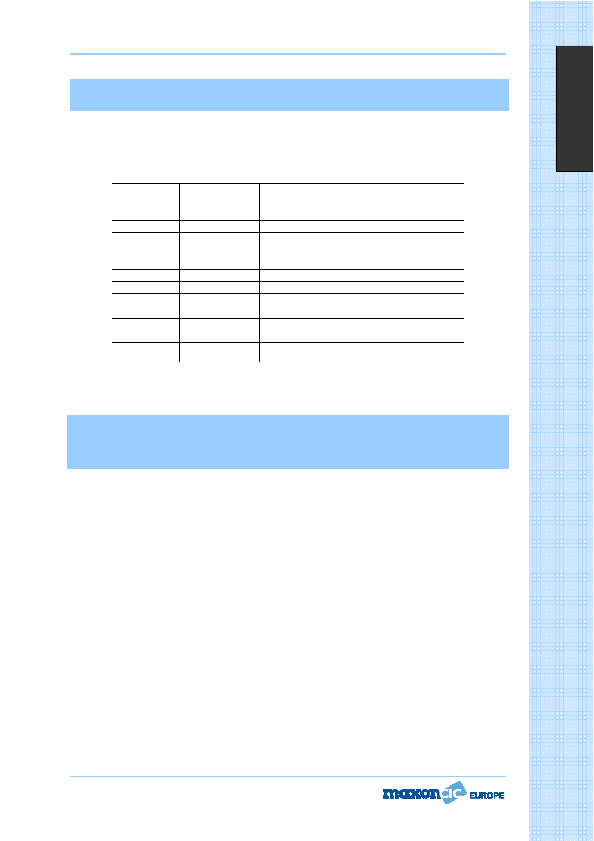
User Manual CM70
Table des bandes de fréquences
L'émetteur/récepteur CM70 inclut un circuit multistandard programmable avancé qui permet la
programmation de différentes bandes de fréquences, spécifications et modes de fonctionnement, en
conformité avec les réglementations du pays dans lequel il est utilisé. Dix bandes de fréquences
programmables sont disponibles, comme l'indique le tableau suivant :
Français
CODE
PAYS
I0 ITALIE 40 V AM / FM 4W
I2 ITALIE 36 V AM / FM 4W
DE ALLEMAGNE 80 V FM 4W - 12 V AM 1W
D2 ALLEMAGNE 40 V FM 4W - 12 V AM 1W
EU EUROPE 40 V FM 4W - 40 V AM 1W
CE CEPT 40 V FM 4W
SP ESPAGNE 40 V AM / FM 4W
FR FRANCE 40 V FM 4W - 40 V AM 1W
UK UK
PL POLOGNE 40 V AM /
Attention ! Cette radio a été préprogrammée en usine sur la bande de fréquences CE (CEPT 40 V FM
4W), puisque cette norme est actuellement acceptée dans tous les pays d'Europe. Consulter la table
d'informations à la page 1 (restrictions sur l'utilisation des émetteurs-récepteurs CB).
Sélection/Programmation des bandes de
fréquesnce
Cette radio doit être programmée et utilisée exclusivement sur une bande de fréquences permise dans le
pays dans lequel elle est utilisée. Pour programmer une bande de fréquences différente, procéder comme
suit :
1) Éteindre la radio.
2) Maintenir enfoncée la touche EMG tout en allumant la radio à l'aide du bouton de marche/arrêt. Relâcher
alors que toutes les icônes sont encore affichées.
3) Le code du pays clignote à l'écran (2 caractères).
4) Sélectionner le nouveau code de pays à l'aide des touches j ou i.
5) Appuyer brièvement sur la touche EMG pour confirmer.
PAYS
SPÉCIFICATIONS (voie, mode de
fonctionnement, puissance de
transmission)
40 V FM 4W FRÉQUENCES DU ROYAUME-UNI 40 V FM 4W FRÉQUENCES DE LA CEPT
FM 4W FRÉQUENCES
POLONAISES
T
T
T
a
a
a
b
b
b
l
l
l
e
e
e
d
d
d
e
e
e
s
s
s
b
b
b
a
a
a
n
n
n
d
d
d
e
e
e
s
s
s
d
d
d
e
e
e
Page 30 of 68
f
f
f
r
r
r
é
é
é
q
q
q
u
u
u
e
e
e
n
n
n
c
c
c
e
e
e
s
s
s
Page 40

User Manual CM70
Installation
Avant d'installer l'unité principale dans un véhicule, vérifier et sélectionner l'emplacement le plus approprié,
pour que la radio soit facile d'accès et d'utilisation confortable, sans toutefois gêner le conducteur ni
interférer avec la conduite. Utiliser le support et le matériel fournis pour l'installation. Serrer fermement les
vis, pour que le support ne se relâche pas sous l'effet des vibrations du véhicule. Le support de montage
dans le véhicule peut être installé au-dessus ou au-dessous de la radio et celle-ci peut être inclinée comme
désiré, selon le type d'installation (sous le tableau de bord ou sous le toit de la cabine).
Installation de l'unité principale
Avant de brancher la radio au circuit électrique du véhicule, vérifier qu'elle est éteinte. Le câble
d'alimentation CC est fourni avec un porte-fusible, le fusible étant situé sur le fil rouge du positif (+).
Connecter ce câble au circuit électrique du véhicule, en faisant particulièrement attention de respecter la
polarité, même si la radio est protégée contre l'inversion de polarité. Connecter le fil rouge au pôle positif
(+) et le fil noir au pôle négatif (-) du circuit électrique du véhicule. Vérifier que les fils et les bornes sont
fermement connectés, afin de prévenir toute déconnexion des câbles ou tout court-circuit.
Installation de l'antenne
Français
Utiliser une antenne mobile spécifiquement réglée pour la plage de fréquences de 27 MHz. Cette antenne
doit être installée par un technicien spécialisé ou un centre de maintenance. Lors de l'installation sur le
véhicule, veiller à relier parfaitement l'antenne à la masse. Avant de connecter l'antenne à la radio, vérifier le
fonctionnement correct de l'antenne avec un faible rapport d'onde stationnaire, en utilisant les instruments
appropriés. Dans le cas contraire, le circuit de transmission de la radio risque d'être endommagé. L'antenne
s'installe habituellement sur la section la plus haute du véhicule, à distance des obstacles et aussi loin que
possible de toute source d'électricité et d'interférence électromagnétique. Le câble coaxial d'antenne RF ne
doit pas être endommagé ni compressé lors de son acheminement entre l'antenne et la radio. Le
fonctionnement correct de l'antenne et le faible rapport d'onde stationnaire doivent être vérifiés
régulièrement. Brancher le câble coaxial d'antenne RF dans le connecteur d'antenne situé sur la face arrière
de la radio.
Essai fonctionnel
Une fois la radio connectée au circuit électrique du véhicule et l'antenne installée, vérifier le fonctionnement
du système. Pour ce faire, procéder comme suit :
17.) Vérifier que l'unité est correctement installée.
18.) Vérifier que le câble d'alimentation est correctement branché.
19.) Vérifier que le connecteur coaxial d'antenne est correctement branché.
20.) Brancher le microphone dans le connecteur du panneau avant.
21.) Allumer l'unité et sélectionner la bande de fréquences correspondant au pays. (Voir page 10.)
22.) Régler le silencieux en position ouverte (bruit du haut-parleur) à l'aide de la touche de mode,
sélectionner la fonction SQ et utiliser les touches
23.) Sélectionner la voie désirée à l'aide des touches
24.) Appuyer sur la touche PTT (interrupteur d'émission) pour transmettre et la relâcher pour recevoir.
j ou i.
j ou i.
Si l'essai réussit, l'unité est prête à l'emploi. En cas de problème, contacter le revendeur.
Page 29 of 68
I
I
I
n
n
n
s
s
s
t
t
t
a
a
a
l
l
l
l
l
l
a
a
a
t
t
t
i
i
i
o
o
o
n
n
n
Page 41

User Manual CM70
MICROPHONE
20
1917 18
Français
16. Touche PTT
Interrupteur d'émission. Chaque pression sur la touche PTT (
de transmettre. Relâcher la touche pour passer en mode de réception.
17. Sélecteur de voie supérieure
Chaque fois que cette touche est actionnée, le numéro de voie monte d'une unité.
* Peut être utilisée au lieu de la touche
18. Touche de mode et de verrouillage
Maintenir cette touche enfoncée pour sélectionner la fonction de verrouillage (LOCK) du clavier et prévenir
toute activation de fonctions indésirables. Lorsque la fonction de verrouillage est activée, l'icône LOCK
s'affiche à l'écran.
Utiliser cette touche pour régler les fonctions de silencieux automatique (ASQ), de silencieux (SQ), de
sonorité des touches (BEEP), de rétroéclairage (BACKLIGHT) et de mémoire (MEMORY). Cette touche est
identique à la touche MODE qui se trouve sur l'avant de la radio.
* Utiliser cette touche également pour augmenter ou diminuer le niveau de volume.
Appuyer plusieurs fois sur la touche de verrouillage et de mode, jusqu'à ce que l'icône
s'affiche à l'écran. Les touches Haut et Bas du microphone permettent également d'augmenter ou de
diminuer le volume.
19. Sélecteur de voie inférieure
Chaque fois que cette touche est actionnée, le numéro de voie baisse d'une unité.
* Peut être utilisée au lieu de la touche
20. Prise de microphone
La prise de microphone à 6 broches et écrou de serrage se branche dans le connecteur de micro à l'avant de
la radio.
Page 28 of 68
i
j
Push-To-Talk
- Appuyer pour émettre) permet
ou
M
M
M
i
i
i
c
c
c
r
r
r
o
o
o
p
p
p
h
h
h
o
o
o
n
n
n
e
e
e
Page 42

User Manual CM70
13. Prise S-METER
Cette prise permet de connecter un dispositif S-METER externe en option.
14. Connecteur d'antenne
Prise permettant le raccordement d'une antenne. Consulter la section relative à l'installation de l'antenne.
15. Cordon d'alimentation 13,8 V CC
Cordon électrique de 13,8 volts CC.
Français
Page 27 of 68
C
C
C
o
o
o
m
m
m
m
m
m
a
a
a
n
n
n
d
d
d
e
e
e
s
s
s
e
e
e
t
t
t
Page 43

User Manual CM70
sélectionnée s'affiche à l'écran. Toutes les données de cette voie sont mémorisées (numéro de voie, relevé
de fréquence, mode AM/FM, puissance de transmission, etc.).
Rappel mémoire
Appuyer sur la touche MODE. Le numéro de voie en mémoire (M0-M9) s'affiche à l'écran. À l'aide des
touches
mode de rappel des voies en mémoire.
8. Glissière Haut et Bas
Les touches
j ou i, sélectionner la voie désirée en mémoire. Rappuyer sur la touche MODE pour quitter le
et permettent d'augmenter et de diminuer le niveau de volume et de silencieux.
Français
9. Touche ESP (
La touche ESP (
exclusive de la radio CB Maxon CM70. Le traitement électronique de la voix agit comme un compresseur de
modulation en mode de transmission, et comme un expanseur de modulation en mode de réception. La
fonction ESP permet d'obtenir des signaux sonores plus puissants et plus clairs dans les zones bruyantes,
particulièrement pour les communications longue distance ou en présence de faibles signaux. L'efficacité de
cette fonction est encore plus impressionnante lors de la communication avec d'autres radios utilisant le
même système. Pour activer ou désactiver
la fonction ESP, appuyer sur la touche ESP. Lorsque la fonction est activée, l'icône ESP s'affiche à l'écran.
Performance de la fonction ESP
sur la modulation
en modes RX et TX
10.
j Touche de défilement rapide vers le bas
Cette touche permet de sélectionner une voie inférieure. Chaque fois qu'elle est actionnée, le numéro de
voie baisse d'une unité. Appuyer sur cette touche pendant environ 2 secondes, et le numéro de voie diminue
de 10 unités.
i Touche de défilement rapide vers le haut
11.
Cette touche permet de sélectionner une voie supérieure. Chaque fois qu'elle est actionnée, le numéro de
voie monte d'une unité. Appuyer sur cette touche pendant environ 2 secondes, et le numéro de voie
augmente de 10 unités.
Electronic Speech Processor
Electronic Speech Processor
)
- Traitement électronique de la voie) est une fonction avancée
Panneau arrière
12. Prise EXT de haut-parleur externe
Cette prise permet de connecter un haut-parleur en option.
Page 26 of 68
C
C
C
o
o
o
m
m
m
m
m
m
a
a
a
n
n
n
d
d
d
e
e
e
s
s
s
e
e
e
t
t
t
Page 44
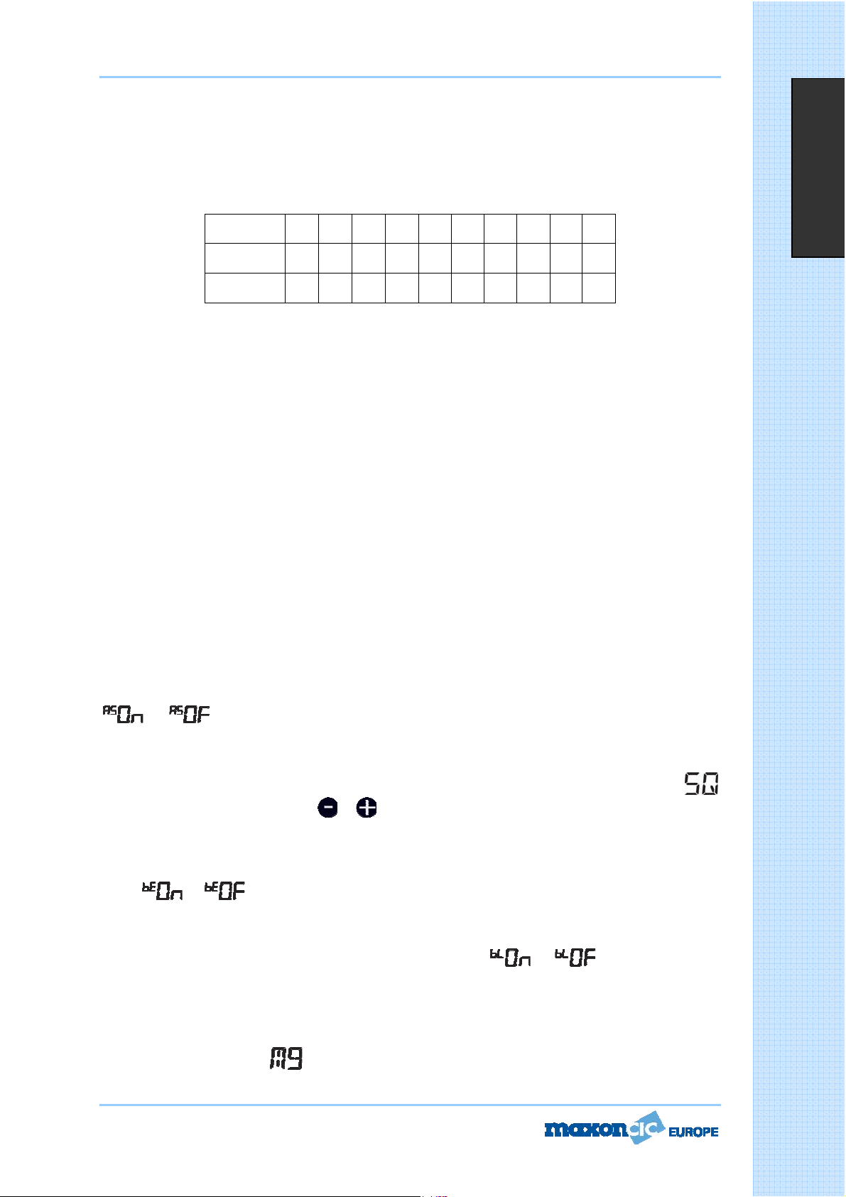
User Manual CM70
3. Touche EMG (voies d'urgence)
Cette touche permet d'accéder rapidement à l'une des deux voies d'urgence préprogrammées (voie 9 ou
voie 19). Chaque fois que la touche est actionnée, la radio sélectionne la voie 9 puis la voie 19 et, de
nouveau, la voie de communication normale. Lorsque l'une des voies d'urgence est sélectionnée, l'icône EMG
s'affiche à l'écran. Le mode de fonctionnement (AM ou FM) des voies d'urgence est programmé en usine,
selon le tableau suivant.
CODE PAYS I0 I2 DE D2 EU CE SP FR UK PL
V 9 AM AM AM AM AM FM AM AM FM AM
V 19 AM AM AM AM AM FM AM AM FM AM
4. Touche AM/FM
Cette touche permet de sélectionner le mode de fonctionnement AM ou FM en réception et en transmission.
Cette sélection de mode n'est possible que si elle est permise sur la bande de fréquences programmée.
5. Touche SCAN
Toute action sur la touche SCAN active la fonction de recherche automatique des voies occupées. Pour
activer la fonction SCAN, commencer par régler le niveau de silencieux (SQUELCH) pour supprimer le bruit
de fond. Ensuite, appuyer sur la touche SCAN. La radio parcourt alors automatiquement toutes les voies
continuellement, et l'icône SCAN s'affiche à l'écran. La recherche automatique s'arrête si un signal est
détecté sur une voie, pour que l'utilisateur puisse entendre le signal entrant. Elle reprend lorsqu'aucun signal
n'est détecté sur cette voie. Si la touche PTT est actionnée dans les cinq secondes, la radio reste sur cette
voie. Dans le cas contraire, la recherche reprend. La recherche automatique peut être reprise à tout
moment. Il suffit pour cela d'appuyer sur la touche SCAN. Pour quitter le mode SCAN, appuyer brièvement
sur la touche PTT
6. Connecteur de microphone
Connecter le microphone dynamique fourni à l'aide de ce connecteur et verrouiller à l'aide de l'écrou.
7. Touche MODE
La touche MODE permet d'activer et de programmer les différentes fonctions de la radio. Toute pression sur
la touche MODE fait défiler les différentes fonctions. La séquence de ces fonctions peut varier selon les
fonctions disponibles.
.
Français
- Commande de silencieux automatique (ASQ)
Pour activer le silencieux automatique, appuyer plusieurs fois sur la touche MODE, jusqu'à ce que l'icône
ou s'affiche à l'écran. À l'aide de la touche j ou i, régler le niveau désiré et appuyer
brièvement sur la touche PTT pour confirmer et mémoriser la sélection.
- Niveau de silencieux
Pour régler le niveau de silencieux, appuyer plusieurs fois sur la touche MODE, jusqu'à ce que l'icône
s'affiche à l'écran. Utiliser les touches et pour augmenter ou diminuer le niveau de silencieux.
- Sonorité des touches
Chaque fois qu'une touche est actionnée, un son est émis, pour confirmer la commande. Il est possible de
désactiver la sonorité des touches. Pour ce faire, appuyer plusieurs fois sur la touche MODE, jusqu'à ce que
l'icône
brièvement sur la touche PTT pour confirmer et mémoriser la sélection.
- Réglage du rétroéclairage de l'écran
Appuyer plusieurs fois sur la touche MODE, jusqu'à ce que l'icône
l'aide de la touche
et mémoriser la sélection.
Programmation de la mémoire (M0 à M9)
Utiliser les touches
MODE, pour afficher l'icône
mémoriser et maintenir enfoncée la touche MODE jusqu'à ce que le numéro de la voie précédemment
Page 25 of 68
ou s'affiche à l'écran. À l'aide de la touche j ou i, régler le niveau désiré et appuyer
ou s'affiche à l'écran. À
j ou i, régler le niveau désiré et appuyer brièvement sur la touche PTT pour confirmer
j ou i pour sélectionner la voie à mémoriser. Appuyer plusieurs fois sur la touche
(M0-M9) à l'écran. À de la touche j ou i, sélectionner une voie à
C
C
C
o
o
o
m
m
m
m
m
m
a
a
a
n
n
n
d
d
d
e
e
e
s
s
s
e
e
e
t
t
t
Page 45

User Manual CM70
C. Icône LOCK
L'icône LOCK s'affiche lorsque la fonction de verrouillage est activée.
D. Icône AM
L'icône AM s'affiche lorsque la radio reçoit et transmet en mode AM (modulation d'amplitude).
E. Icône FM
L'icône FM s'affiche lorsque la radio reçoit et transmet en mode FM (modulation de fréquence).
F. Icône DW
L'icône DW s'affiche lorsque la fonction de surveillance automatique de deux voies (
activée.
La fonction DW permet de surveiller en alternance deux voies programmables. Sélectionner la première voie
à surveiller à l'aide des touches
activer la fonction DW, maintenir enfoncée la touche EMG jusqu'à ce que l'icône DW s'affiche et clignote à
l'écran. Sélectionner ensuite la seconde voie à surveiller à l'aide des touches
de sélection de voie du microphone. Maintenir enfoncée la touche EMG. La fonction DW est alors activée, et
l'écran LCD affiche alternativement le numéro de voie de chacune des voies programmées. L'icône DW
s'affiche à l'écran LCD. La surveillance s'interrompt si un signal est détecté sur l'une des deux voies, pour
que l'utilisateur puisse écouter le signal entrant, et elle reprend dès qu'aucun signal n'est détecté sur cette
voie. Il est possible de transmettre sur cette voie, en appuyant simplement sur la touche PTT. En l'absence
de transmission dans les 5 secondes, la surveillance reprend. Pour quitter le mode DW, appuyer brièvement
sur le bouton PTT.
G. Code alphanumérique international
G. Ces deux caractères indiquent le code du pays, conformément à la bande de fréquences programmée
(par exemple, FR, DE, UK, CE, etc.).
H. et I. Ces trois chiffres indiquent le numéro de voie en cours d'utilisation (de 01 à 80, selon la bande de
fréquences programmée), lorsque la fonction de lecture du numéro de voie est activée.
j et i, ou à l'aide des touches de sélection de voie du microphone. Pour
j et i, ou à l'aide des touches
DUAL WATCH
- DW) est
Français
J. Icône ASQ
L'icône ASQ s'affiche lorsque la fonction de silencieux automatique (
K. Icône LO
L'icône LO s'affiche lorsque l'émetteur fonctionne en mode basse puissance (
1W.
L. Icône TX
L'icône TX s'affiche lorsque la radio fonctionne en mode de transmission.
M. Icône RX
L'icône RX s'affiche lorsque la radio fonctionne en mode de réception.
N. Icône SQ
L'icône SQ s'affiche lors du réglage de la commande de silencieux (
O. Indicateur numérique de volume et de silencieux
Cet indicateur numérique à 10 barrettes affiche le niveau de volume et de silencieux.
P. Indicateur numérique de signal
L'indicateur numérique de signal à 10 barrettes montre la puissance du signal reçu (de S0 à S9+30) en
mode de réception, et du signal transmis (0 à 4W) en mode de transmission.
Q. Icône EMG
L'icône EMG s'affiche lorsque l'une des voies d'urgence (
sélectionnée.
R. Icône SCAN
L'icône SCAN s'affiche lorsque la fonction de recherche automatique de voies occupées est activée.
Page 24 of 68
Auto Squelch
Squelch
EMERGENCY
- SQ).
- ASQ) est activée.
LOW POWER
- EMG) préprogrammée est
- LO), à savoir
C
C
C
o
o
o
m
m
m
m
m
m
a
a
a
n
n
n
d
d
d
e
e
e
s
s
s
e
e
e
t
t
t
Page 46

User Manual CM70
Commandes et fonctionnement
Panneau avant
Français
1. Marche/Arrêt
Ce bouton allume et éteint la radio
2. Écran LCD
Ce grand écran rétroéclairé rouge permet une bonne lisibilité. Il affiche toutes les fonctions activées ainsi
que d'autres caractéristiques programmées par l'utilisateur, telles que la voie ou la fréquence à cinq chiffres.
Le système inclut également un indicateur de puissance des signaux reçus et transmis à 10 barrettes.
.
C
C
C
o
o
o
m
m
m
A. Icône VOL
L'icône VOL s'affiche lorsque le volume est réglé.
B. Icône ESP C E
L'icône ESP s'affiche lorsque la fonction de traitement électronique de la voix (
ESP) est activée.
Page 23 of 68
Electronic Speech Processor
-
m
m
m
a
a
a
n
n
n
d
d
d
e
e
e
s
s
s
e
e
e
t
t
t
Page 47

User Manual CM70
Spécifications
Généralités
Voies .................................................................................................................40, AM/FM 4W
Plage de fréquences............................................................................26.565 à 27.99125 MHz
Commande de fréquences .................................................................................................. PLL
Température de fonctionnement........................................................................ -10
Tension CC en entrée ......................................................................................13,2 V CC
Dimensions ..............................................................................182 (L) X 37 (H) X 139 (P) mm
Poids ........................................................................................................................... 0,850 kg
Récepteur
Système récepteur...................................................... Super hétérodyne à double conversion
e
Fréquence intermédiaire.................................................. 1
Sensibilité .................................................................... 0,5
Distorsion audio................................................................................ Inférieure à 8 % à 1 KHz
FI : 10.695 MHz, 2e FI : 455 MHZ
PV pour 20 db SINAD en mode FM
q / +55qC
r15%
Français
Affaiblissement sur fréquence image ..............................................................................65 dB
Sélectivité pour la voie adjacente....................................................................................65 dB
Rapport Signal/ bruit.......................................................................................................45 dB
Débit de courant en veille..........................................................................................0,250 mA
Débit de courant en audio max.....................................................................................650 mA
Émetteur
Puissance en sortie .......................................................................................... 4W à 13,2 V CC
Modulation.............................................................................................FM : 1,8 KHz
Réponse en fréquence ............................................................................. De 400 Hz à 2,5 KHz
Impédance en sortie........................................................................ RF 50 ohm dissymétrique
Rapport Signal/ bruit............................................................................................... 40 dB MIN
Débit de courant ........................................................................................................1 200 mA
r0,2 KHz
S
S
S
p
p
p
é
é
é
c
c
c
i
i
i
f
f
f
i
i
i
c
c
c
a
a
a
t
t
t
i
i
i
o
o
o
n
n
n
s
s
s
Page 22 of 68
Page 48

User Manual CM70
Sommaire
Spécifications ...............................................................................................................22
Commandes et fonctionnement................................................................................. 23-27
Microphone ..................................................................................................................28
Installation...................................................................................................................29
Installation de l'unité principale......................................................................................29
Installation de l'antenne ................................................................................................29
Essai fonctionnel...........................................................................................................29
Table des bandes de fréquences ....................................................................................30
Sélection des bandes de fréquences ...............................................................................30
Table de restrictions......................................................................................................61
Informations à jour sur les restrictions nationales ............................................................62
Diagrammes............................................................................................................ 63-67
Déclaration de conformité..............................................................................................68
Français
Page 21 of 68
S
S
S
o
o
o
m
m
m
m
m
m
a
a
a
i
i
i
r
r
r
e
e
e
Page 49

User Manual CM70
joi
Tabla de bandas de frecuencia
El transceptor CM70 incluye un circuito programable multiestándar avanzado que permite al usuario
programar diferentes bandas de frecuencia, especificaciones y modos de funcionamiento (de conformidad
con la normativa del país en que se utilice el producto). Hay disponibles 10 bandas de frecuencias
programables, conforme a la siguiente tabla:
CÓDIGO
DE PAÍS
I0 ITALIA 40CH AM / FM 4W
I2 ITALIA 36CH AM / FM 4W
DE ALEMANIA 80CH FM 4W - 12CH AM 1W
D2 ALEMANIA 40CH FM 4W - 12CH AM 1W
EU EUROPA 40CH FM 4W - 40CH AM 1W
CE CEPT 40CH FM 4W
SP ESPAÑA 40CH AM / FM 4W
FR FRANCIA 40CH FM 4W - 40CH AM 1W
UK REINO UNIDO
PL POLONIA 40CH AM /
¡Atención! Esta radio se ha preprogramado en fábrica en la banda de frecuencias CE (CEPT 40CH FM
4W), ya que este estándar es aceptado actualmente por todos los países europeos. Consulte la tabla
informativa (Restricciones al uso de transceptores CB).
PAÍS
ESPECIFICACIONES (Canales, modos
operativos, potencia de TX)
40CH FM 4W FRECUENCIAS DE RU -40CH FM
4W FRECUENCIAS CEPT
FM 4W FRECUENCIAS
POLACAS
Español
Selección/programación de bandas de
frecuencia
La radio debe programarse y utilizarse exclusivamente en una banda de frecuencias permitida en el país en
el que se utiliza. Es posible programar otra banda de frecuencias diferente siguiendo este procedimiento:
1) Apague la radio.
2) Mantenga pulsado el botón EMG mientras enciende la radio, empleando el control de potencia. Suéltelo
mientras están todavía iluminados todos los iconos mostrados.
3) El código de país actual parpadeará en la pantalla LCD (2 dígitos).
4) Seguidamente, seleccione el nuevo código de país que desee mediante
5) Pulse brevemente el botón EMG para confirmar.
Page 20 of 68
.
T
T
T
a
a
a
b
b
b
l
l
l
e
e
e
d
d
d
e
e
e
b
b
b
a
a
a
n
n
n
d
d
d
a
a
a
s
s
s
d
d
d
e
e
e
f
f
f
r
r
r
e
e
e
c
c
c
u
u
u
e
e
e
n
n
n
c
c
c
i
i
i
a
a
a
Page 50

User Manual CM70
joi
joi
Instalación
Antes de instalar la unidad principal en un vehículo, compruebe y seleccione el lugar más cómodo, de
manera que la radio sea fácilmente accesible y se pueda operar con ella con comodidad y sin interferir en la
conducción del vehículo. Utilice el soporte y el material suministrados para instalar la radio. Los tornillos del
soporte deben apretarse bien para evitar que se suelten con las vibraciones del vehículo. El soporte para
montaje en vehículo puede instalarse encima o debajo de la radio. La radio puede inclinarse como se desee
para adaptarla al tipo de instalación de que se trate (instalación debajo del salpicadero o en el techo de la
cabina de un camión).
Instalación de la unidad principal
Antes de conectar la radio al sistema eléctrico del vehículo, asegúrese de que la radio está apagada. El cable
de alimentación de CC está provisto de un portafusible (el fusible está situado en el hilo rojo positivo (+)).
Conecte el cable de alimentación de CC al sistema eléctrico del vehículo. Preste especial atención a la
polaridad aunque la radio disponga de protección contra inversiones de polaridad. Conecte el hilo rojo al
polo positivo (+) y el hilo negro, al polo negativo (-) del sistema eléctrico del vehículo. Asegúrese de que los
hilos y terminales están conectados de manera firme para evitar que los cables se desconecten o provoquen
cortocircuitos.
Instalación de la antena
Debe utilizarse una antena móvil específica ajustada al rango de frecuencias de 27 MHz. La instalación de la
antena deberá realizarla un técnico o centro de servicio especializado. Tenga especial cuidado al instalar la
antena en el vehículo para que ésta esté perfectamente conectada a tierra. Antes de conectar la antena a la
radio, es necesario comprobar el correcto funcionamiento de la antena con baja relación de onda
estacionaria (S.W.R.) mediante el uso de los instrumentos adecuados. De no ser así, podría dañarse el
circuito del transmisor de la radio. La antena suele instalarse en la parte más alta del vehículo, libre de
obstáculos y lo más alejada posible de cualquier fuente de electricidad o ruido electromagnético. El cable
coaxial de la antena RF no debe dañarse ni presionarse en su tendido desde la antena hasta la radio. El
correcto funcionamiento de la antena y la baja relación de onda estacionaria (S.W.R.) deberán comprobarse
periódicamente. Conecte el cable coaxial de la antena RF al conector de antena, situado en la parte posterior
de la radio.
Español
Prueba de funcionamiento
Una vez que la radio esté conectada a la fuente de alimentación del vehículo y que la antena esté instalada,
podrá comprobarse el correcto funcionamiento del sistema. Proceda del siguiente modo:
9.) Asegúrese de que la unidad está correctamente instalada.
10.) Compruebe que el cable de alimentación esté correctamente conectado.
11.) Compruebe que el conector coaxial de antena RF esté correctamente ajustado.
12.) Conecte el micrófono al conector del panel delantero.
13.)Encienda la unidad y seleccione la banda de frecuencias correcta para el país en el que se va a
utilizar. (véase la página 10)
14.) Abra el silenciador (para que se reciba ruido del altavoz) mediante el botón MODE, seleccione SQ y
.
.
utilice
15.) Seleccione el canal deseado mediante
16.)Pulse el botón PTT (Push To Talk: pulsar para hablar) para transmitir y suéltelo para recibir.
Si la prueba es correcta, la unidad está lista para ser utilizada. Si se produce algún problema, póngase
en contacto con su distribuidor.
Page 19 of 68
I
I
I
n
n
n
s
s
s
t
t
t
a
a
a
l
l
l
a
a
a
c
c
c
i
i
i
ó
ó
ó
n
n
n
Page 51

User Manual CM70
i
j
MICRÓFONO
1916 17 18
Español
20
16. Botón PTT (Push-to-Talk)
Botón de transmisor. Pulse el botón PTT para transmitir y suéltelo para regresar al modo de recepción.
17. Botón Arriba (selector de canal)
Cada vez que se pulsa este botón, aumenta en 1 el número de canal.
* Se puede utilizar en lugar de
18. Botón LOCK/MODE
La función LOCK (bloqueo) se activa manteniendo pulsado este botón, con lo que se bloquea el teclado y se
impide la activación no deseada de funciones. Cuando esté activada la función LOCK, aparecerá el icono
LOCK en la pantalla LCD.
Puede utilizar este botón para establecer ASQ (silenciador automático), SQ (nivel de silenciador), el tono de
pitido, la iluminación posterior y la memoria. Este botón es el mismo que el botón MODE situado en la parte
delantera de la radio.
* También puede utilizar este botón para aumentar o reducir el nivel de volumen.
Pulse el botón LOCK/MODE repetidamente hasta que aparezca el icono
También se pueden utilizar los botones UP o DN del micrófono para aumentar o reducir el nivel de volumen.
o en la pantalla LCD.
19. Botón Abajo (selector de canal)
Cada vez que se pulsa este botón, se reduce en 1 el número de canal.
* Se puede utilizar en lugar de
20. Conector para MICRÓFONO
El conector para micrófono de 6 patillas con tuerca de anillo para bloqueo se conecta al conector para
micrófono situado en la parte delantera de la radio.
Page 18 of 68
M
M
M
i
i
i
c
c
c
r
r
r
o
o
o
f
f
f
ó
ó
ó
n
n
n
o
o
o
Page 52

User Manual CM70
12. Conector (de altavoz externo) EXT
Este conector permite la conexión de un altavoz externo (opcional).
13. Conector S-METER
Este conector permite la conexión de un S-METER externo (opcional).
14. Conector de antena (ANTENNA)
Conector de antena. Consulte la sección INSTALACIÓN DE LA ANTENA.
15. CABLE DE CORRIENTE DE 13,8 VCC
Entrada de cable de corriente de 13,8 VCC.
Español
Page 17 of 68
C
C
C
o
o
o
n
n
n
t
t
t
r
r
r
o
o
o
l
l
l
y
y
y
u
u
u
t
t
t
i
i
i
l
l
l
i
i
i
z
z
z
a
a
a
c
c
c
i
i
i
ó
ó
ó
n
n
n
Page 53

User Manual CM70
i
joi
PROGRAMACIÓN DE CANALES DE MEMORIA (M0-M9)
Utilice el botón joipara seleccionar el canal que debe almacenarse como canal de memoria. Pulse el
botón MODE repetidamente hasta que aparezca el icono
para seleccionar el número de canal que desea almacenar en la memoria, mantenga pulsado el botón MODE
hasta que aparezca en la pantalla LCD el número del canal previamente seleccionado. Se guardarán todos
los datos de dicho canal (número de canal, lectura de frecuencia, modo AM/FM, potencia de transmisor,
etc.).
RECUPERACIÓN DE CANALES DE LA MEMORIA
Pulse la tecla MODE para que aparezca el número de canal de la memoria (M0-M9) en la pantalla LCD.
Utilice
modo de recuperación de canales de la memoria.
8. BARRA DESLIZANTE ARRIBA - ABAJO
Utilice
9. Botón ESP (Electronic Speech Processor: procesador electrónico de voz)
ESP (procesador electrónico de voz) es una función avanzada exclusiva de la radio Maxon CM70 CB. ESP
funciona como compresor de modulación durante la transmisión y como expansor de modulación durante el
modo de recepción. ESP obtiene señales de audio más potentes, limpias y claras, lo que es de gran ayuda
en lugares ruidosos, y particularmente en el caso de comunicaciones a larga distancia o de señales débiles.
La eficiencia de ESP es aun mayor al comunicar con otras radios que utilizan el mismo sistema. Para activar
o desactivar la función ESP, pulse el botón ESP. Cuando esté activada, aparecerá el icono ESP en la pantalla
LCD.
para seleccionar el canal de memoria deseado. Pulse el botón MODE de nuevo para salir del
y para aumentar o reducir el nivel de volumen y de silenciador.
(M0-M9) en la pantalla LCD. Utilice jo
Español
Rendimiento ESP
de la modulación
en modos RX y TX
10. Botón
Este botón permite la selección rápida del canal de funcionamiento hacia abajo. Cada vez que se pulsa este
botón, se reduce en 1 el número de canal. Pulse este botón durante 2 segundos para bajar 10 canales.
Botón i (aumento rápido)
11.
Este botón permite la selección rápida del canal de funcionamiento en incrementos. Cada vez que se pulsa
este botón, aumenta en 1 el número de canal. Mantenga pulsado este botón para cambiar de 10 en 10 el
número de canal.
Panel posterior
j (descenso rápido)
C
C
C
o
o
o
n
n
n
t
t
t
r
r
r
o
o
o
l
l
l
y
y
y
Page 16 of 68
u
u
u
t
t
t
i
i
i
l
l
l
i
i
i
z
z
z
a
a
a
c
c
c
i
i
i
ó
ó
ó
n
n
n
Page 54

User Manual CM70
j
3. Botón EMG (canales de emergencia)
Este botón permite un acceso rápido a uno de los dos canales de emergencia preprogramados (CH9 o
CH19). Cada vez que se pulsa este botón, la radio selecciona CH9, luego CH19 y, después, de nuevo el canal
de funcionamiento normal. Cuando se selecciona uno de los canales de emergencia, aparece el icono EMG
en la pantalla LCD. El modo de funcionamiento (AM o FM) para los canales de emergencia está
preprogramado en fábrica conforme a la siguiente tabla.
Español
CÓDIGO DE
PAÍS
CH-9 AM AM AM AM AM FM AM AM FM AM
CH-19 AM AM AM AM AM FM AM AM FM AM
4. Botón AM/FM
Este botón permite al usuario seleccionar el modo de funcionamiento en AM o FM tanto en RX como en TX.
La selección de modo de funcionamiento AM/FM sólo es posible si se permite en la banda de frecuencias
programada.
5. Botón SCAN
Al pulsar el botón SCAN, se activa la función SCAN (búsqueda automática de canales ocupados). Para activar
la función SCAN, ajuste en primer lugar el nivel de SQUELCH (silenciador) hasta que se corte el ruido de
fondo. Seguidamente, pulse el botón SCAN, tras lo cual la radio comenzará a buscar automáticamente todos
los canales de manera continua y se mostrará el icono SCAN en el LCD. La búsqueda automática se
detendrá si se detecta una señal en un canal (con el fin de permitir al usuario escuchar la señal entrante) y
comenzará de nuevo cuando no se detecte ninguna señal en dicho canal. Si se pulsa el botón PTT antes de
que transcurran 5 segundos, la radio permanecerá en dicho canal. De lo contrario, la búsqueda comenzará
de nuevo. La búsqueda automática también puede reiniciarse en cualquier momento pulsando el botón
SCAN. Para salir del modo SCAN, pulse brevemente el botón PTT
6. Conector para micrófono
Conecte el micrófono dinámico suministrado a través de este conector y bloquéelo mediante la tuerca de
anillo.
I0 I2 DE D2 EU CE SP FR UK PL
.
7. Botón MODE
Utilice el botón MODE para activar y programar las diversas funciones de la radio. Pulsando la tecla MODE,
se desplazará entre las distintas funciones. La secuencia de las funciones puede variar en función de las
funciones actuales.
- Control de silenciador automático ASQ
Para activar el control de silenciador automático (Auto Squelch), pulse la tecla MODE repetidamente hasta
que aparezca el icono
pulse brevemente el botón PTT para confirmar y guardar la selección.
- NIVEL DE SILENCIADOR
Cuando desee ajustar el nivel de silenciador, pulse la tecla MODE repetidamente hasta que aparezca el icono
en la pantalla LCD. Utilice y para aumentar o reducir el nivel de silenciador.
- TONO DE PITIDO
Al pulsar un botón, suena un pitido para confirmar la orden. Puede activar o desactivar este tono de pitido
pulsando la tecla MODE repetidamente hasta que aparezca el icono
Utilice joi para establecer el nivel deseado y pulse brevemente el botón PTT para confirmar y guardar la
selección.
- AJUSTE DE LA ILUMINACIÓN POSTERIOR DE LA PANTALLA LCD
Pulse la tecla MODE repetidamente hasta que aparezca el icono
oi para establecer el nivel deseado y pulse brevemente el botón PTT para confirmar y guardar la
selección.
Page 15 of 68
o en la pantalla LCD. Utilice joi para establecer el nivel deseado y
o en la pantalla LCD.
o en la pantalla LCD. Utilice
C
C
C
o
o
o
n
n
n
t
t
t
r
r
r
o
o
o
l
l
l
y
y
y
u
u
u
t
t
t
i
i
i
l
l
l
i
i
i
z
z
z
a
a
a
c
c
c
i
i
i
ó
ó
ó
n
n
n
Page 55

User Manual CM70
j
j
C. Icono LOCK
El icono LOCK está visible cuando está activada la función LOCK (bloqueo).
D. Icono AM
El icono AM está visible cuando la radio recibe y transmite en modo AM (modulación de amplitud).
E. Icono FM
El icono FM está visible cuando la radio recibe y transmite en modo FM (frecuencia modulada).
F. Icono DW
El icono DW está visible cuando está activada la función DUAL WATCH (supervisión dual: supervisión
automática de dos canales).
La función DW permite la supervisión alterna automática de dos canales programables. Seleccione el primer
canal que debe supervisarse mediante
activar la función DW, mantenga pulsado el botón EMG hasta que el icono DW aparezca y parpadee en la
pantalla LCD. Seguidamente, seleccione el segundo canal que debe supervisarse mediante
botones de selección de canal del micrófono. Mantenga pulsado el botón EMG. La función DW quedará
activada y la pantalla LCD mostrará de forma alterna los números de los dos canales programados. El icono
DW estará visible en la pantalla LCD. La supervisión se detiene si se detecta una señal en uno de los dos
canales, con el fin de permitir al usuario escuchar la señal entrante, y comenzará de nuevo cuando no se
detecte ninguna señal en dicho canal. Es posible transmitir en dicho canal simplemente pulsando el botón
PTT. Si no hay transmisión en 5 segundos, se reiniciará la supervisión. Para salir del modo DW, pulse
brevemente el botón PTT.
G. H. I. Dígito alfanumérico
G. Estos dos dígitos alfanuméricos indican el código de país conforme a la banda de frecuencias programada
(es decir, DE, UK, CE, etc.).
y i o los botones de selección de canal del micrófono. Para
y i o los
Español
H. I. Estos tres dígitos alfanuméricos indican el número del canal operativo (de 01 a 80, en función de la
banda de frecuencias programada), cuando está activada la función de lectura del número de canal.
J. Icono ASQ
El icono ASQ está visible cuando está activada la función Auto Squelch (silenciador automático).
K. Icono LO
El icono LO está visible cuando el transmisor está en modo LOW POWER (baja potencia: 1W).
L. Icono TX
El icono TX está visible cuando la radio está en modo de transmisión.
M. Icono RX
El icono RX está visible cuando la radio está en modo de recepción.
N. Icono SQ
El icono SQ está visible al ajustar el control de silenciador.
O. Icono de nivel digital de volumen / silenciador
Indicador digital de 10 barras que muestra el nivel del volumen y el silenciador.
P. Medidor digital de S/RF
Medidor S/RF digital de 10 barras que indica la potencia de la señal recibida (de S0 a S9+30) en modo de
recepción y la potencia de salida RF del transmisor (de 0 a 4W) en modo de transmisión.
Q. Icono EMG
El icono EMG está visible cuando se selecciona uno de los canales de emergencia preprogramados.
R. Icono SCAN
El icono SCAN está visible cuando está activada la función SCAN (búsqueda automática de canales
ocupados).
Page 14 of 68
C
C
C
o
o
o
n
n
n
t
t
t
r
r
r
o
o
o
l
l
l
y
y
y
u
u
u
t
t
t
i
i
i
l
l
l
i
i
i
z
z
z
a
a
a
c
c
c
i
i
i
ó
ó
ó
n
n
n
Page 56

User Manual CM70
Control y utilización
Panel delantero
Español
1. Encendido/apagado
Este control enciende y apaga la radio
2. Pantalla LCD
Esta pantalla grande y con iluminación posterior resulta fácilmente legible. La pantalla LCD muestra todas las
funciones activadas, así como otras funciones (programables por el usuario), como la lectura de canales o la
lectura de frecuencias completa de 5 dígitos. También incluye un medidor S/RF digital de 10 barras para
supervisar la potencia de las señales recibida y transmitida.
.
C
C
C
o
o
o
n
n
n
t
t
t
r
r
r
o
o
o
l
l
l
y
y
y
A. Icono VOL
El icono VOL está visible cuando se realizan ajustes en el control de volumen.
B. Icono ESP C E
El icono ESP está visible cuando está activada la función ESP (Electronic Speech Processor: procesador
electrónico de voz).
Page 13 of 68
u
u
u
t
t
t
i
i
i
l
l
l
i
i
i
z
z
z
a
a
a
c
c
c
i
i
i
ó
ó
ó
n
n
n
I
Page 57

User Manual CM70
q
r
P
r
Especificaciones
Generales
Canales………………………………………..…………...……………………………....40 canales AM/FM 4W
Rango de frecuencias….……………………………………….………….…...…………..26.565 a 27.99125
MHz
Control de frecuencia……………………………………………….……………………………..……………PLL
Español
Rango de temperaturas de funcionamiento………………………………………..……….-10
Tensión de entrada de CC……………………...………………………………...……......…13,2 V CC
Tamaño…………………………………….……………………………………….182(L) X 37(A) X 139(P) mm
Peso………………………………………………………………………………………...…………………0,850 kg
Receptor
Sistema de recepción………………………………………………….Superheterodino de conversión dual
Frecuencia intermedia …………………………………………….….1ª IF: 10.695 MHz, 2ª IF: 455 MHz
Sensibilidad………………………………………………..………….0,5
Distorsión de sonido……………………………………………………………………Inferior al 8% @ 1 KHz
Rechazo de imagen…………………………………………………………………………………………..65 dB
Rechazo de canal adyacente……………………………………………………………………………….65 dB
Relación señal/ruido………………………………………………………………………………………….45 dB
Consumo de corriente en standby……………………………………..…………….…………………250 mA
V para 20 db SINAD en modo FM
/ +55qC
15%
Consumo de corriente con máximo nivel de audio…………………………….……………………650 mA
Transmisor
Potencia de salida…………………………………………………………………………..…….4W @ 13,2 V CC
Modulación……………………………………………………..……………………...……FM: 1.8 KHz
Respuesta de frecuencia……………………..……………………..…….……………...De 400 Hz a 2.5 KHz
Impedancia de salida…………………………………………………...………RF 50 ohmios, desequilibrio
Relación señal/ruido………………………………………………………………….………………..40 dB MÍN
Consumo de corriente………………………………………………………………………….……….1200 mA
Page 12 of 68
0.2 KHz
E
E
E
s
s
s
p
p
p
e
e
e
c
c
c
i
i
i
f
f
f
i
i
i
c
c
c
a
a
a
c
c
c
i
i
i
o
o
o
n
n
n
e
e
e
s
s
s
Page 58

User Manual CM70
Contenido
Especificaciones ...........................................................................................................12
Control y utilización ................................................................................................. 13-17
Microfóno ....................................................................................................................18
Instalación ..................................................................................................................19
Instalación de la unidad principal ..................................................................................19
Instalación de la antena ...............................................................................................19
Prueba de funcionamiento ............................................................................................19
Tabla de bandas de frecuencia.......................................................................................20
Selección de bandas de frecuencia ................................................................................20
Tabla de restricciones ...................................................................................................61
Información actualizada sobre restricciones nacionales ....................................................62
Diagramas .............................................................................................................. 63-67
Español
Declaración de conformidad ..........................................................................................68
Page 11 of 68
C
C
C
o
o
o
n
n
n
t
t
t
e
e
e
n
n
n
i
i
i
d
d
d
o
o
o
Page 59

User Manual CM70
Frequency Bands Table
The CM70 transceiver includes an advanced multi-standard programmable circuit, which allows the user to
program different frequency bands, specifications and operating modes (in conformity with the regulations
in the country where the product is being used). 10 programmable frequency bands are available, as per the
below table:
English
COUNTRY
CODE
I0 ITALY 40CH AM / FM 4W
I2 ITALY 36CH AM / FM 4W
DE GERMANY 80CH FM 4W - 12CH AM 1W
D2 GERMANY 40CH FM 4W - 12CH AM 1W
EU EUROPE 40CH FM 4W - 40CH AM 1W
CE CEPT 40CH FM 4W
SP SPAIN 40CH AM / FM 4W
FR FRANCE 40CH FM 4W - 40CH AM 1W
UK UK
PL POLAND 40CH AM / FM 4W POLISH FREQUENCIES
Attention! This radio has been factory pre-programmed on the CE frequency band (CEPT 40CH FM 4W),
since this standard is currently accepted in all the European countries. Please refer to the information table
(Restrictions on the use of CB transceivers).
Frequency Band Selection/Programming
The radio must be programmed and used exclusively on a frequency band allowed in the country where the
product is used. It is possible to program a different frequency band, as per the following procedures:
1) Switch off the radio.
2) Press and hold the EMG key while turning on the radio, using the Power knob – Release while
all displayed icons are still lit.
3) The current country code will blink on the LCD display (2 digits).
4) Now select the desired new country code, using the jori.
5) Shortly press the EMG key to confirm.
COUNTRY
SPECIFICATIONS (CH, operating
modes, TX power)
40CH FM 4W UK FREQUENCIES -40CH FM 4W
CEPT FREQUENCIES
Page 10 of 68
F
F
F
r
r
r
e
e
e
q
q
q
u
u
u
e
e
e
n
n
n
c
c
c
y
y
y
b
b
b
a
a
a
n
n
n
d
d
d
T
T
T
a
a
a
b
b
b
l
l
l
e
e
e
Page 60

User Manual CM70
jori
jori
Installation
Before installing the main unit in a vehicle, check and select the most convenient location, so the radio will
be easy to reach and comfortable to operate, without disturbing or interfering with operating the vehicle.
Use the supplied bracket and hardware to install the radio. The bracket screws must be well tightened in
order not to become loose with vehicle vibrations. The car mounting bracket can be installed above or below
the radio and the radio may be tilted as desired according to the specific type of installation (under
dashboard or track cabin roof installation).
Installation of Main Unit
Before connecting the radio to the vehicles electrical system, ensure that radio is switched off. The DC
power cable is complete with a fuse holder (fuse located on the red positive (+) wire). Connect the DC
power cable to the vehicles electrical system, pay special attention to correct polarity, even if the radio is
protected against polarity inversion. Connect the red wire to the positive (+) pole and the black wire to the
negative (-) pole of the vehicles electrical system. Ensure that wires and terminals are firmly connected, in
order to prevent cables from disconnecting or causing short circuits.
Installation of the Antenna
A specific mobile antenna adjusted for 27 MHz frequency range must be used. The antenna installation must
be carried out by a specialist technician or service centre. Please take special care to fully install the antenna
on the vehicle with a perfect connection to ground. Before connecting the antenna to the radio, it is
necessary to check the correct operation of the antenna with low standing wave ratio (S.W.R.), using
adequate instruments. If not, the transmitter circuit of the radio could be damaged. The antenna is usually
installed on the highest part of the vehicle, free from obstacles and as far away as possible from any source
of electric or electromagnetic noise. The RF antenna coaxial cable must not be damaged or pressed on its
way between antenna and the radio. The correct operation of the antenna and the low standing wave ratio
(S.W.R.) must be checked periodically. Connect the RF antenna coaxial cable to the antenna Connector,
located on the rear side of the radio.
English
Operational Test
Once the radio has been connected to the vehicles power supply and the antenna is installed, the operation
of the system can be check and tested. Please proceed as follows:
1.) Make sue the unit is installed correctly.
2.) Check that the power cable is fitted correctly.
3.) Check that RF antenna coaxial connector is correctly fitted.
4.) Fit the microphone to the front panel connector.
5.) Power on the unit and select correct Frequency band for country of use. (see page 10)
6.) Adjust the squelch to be open (noise from speaker) via mode key, select SQ and use
7.) Select desired channel using
8.) Press PTT (Push To Talk) to transmit and release to receive.
If the test is successful the unit is ready to use. If you incur any problems please contact your dealer.
Page 9 of 68
.
.
I
I
I
n
n
n
s
s
s
t
t
t
a
a
a
l
l
l
l
l
l
a
a
a
t
t
t
i
i
i
o
o
o
n
n
n
Page 61

User Manual CM70
i
j
MICROPHONE
1916 17 18
English
20
16. PTT (Push-to-Talk) Key
Transmitter key. Press the PTT key to transmit and release it to return to the receive mode.
17. UP (Channel Selector) Key
Each time this key is pressed, the channel number will move upward by one channel.
* Can be used instead of
18. LOCK/MODE Key
The LOCK function is enabled by a press/hold of this key locks the keypad and prevents the activation of
unwanted features. When the LOCK function is enabled, the LOCK icon appears on the LCD display.
You can use this key to set ASQ, SQ, BEEP TONE, BACKLIGHT and MEMORY. This key is the same as the
MODE Key on the front of the radio.
* You can also use this key for increasing or decreasing volume level.
Pressing the LOCK/MODE key several times, until the icon
KEY or DN Key on microphone can also be used to increase or decrease the volume level.
19. DOWN (Channel Selector) Key
Each time this key is pressed, the channel number will move downward by one channel.
* Can be used instead of
20. MICROPHONE Plug
The 6-pin microphone plug with locking ring nut is connected to the microphone connector located on the
front of the radio.
Page 8 of 68
or appears on the LCD. The UP
C
C
C
o
o
o
n
n
n
t
t
t
r
r
r
o
o
o
l
l
l
a
a
a
n
n
n
d
d
d
O
O
O
p
p
p
e
e
e
r
r
r
a
a
a
t
t
t
i
i
i
o
o
o
n
n
n
Page 62

User Manual CM70
8. UP – Down SLIDE BAR
Use the
9. ESP (Electronic Speech Processor) Key
The ESP (Electronic Speech Processor) is an exclusive advanced feature of the Maxon CM70 CB radio. ESP
(Electronic Speech Processor), works as a modulation compressor during transmission and as a modulation
expander during receive mode. The ESP obtains stronger, cleaner and clearer audio signals, great help in
noisy areas especially in the case of long distance communication or weak signals. The efficiency of ESP is
even greater when communicating with other radios using the same system. To enable or disable
the ESP function, press the ESP key. When enabled, the ESP icon appears on the LCD display.
ESP performance
of the modulation
in RX and TX modes
10.
This key allows fast selection of the operating channel downward. Each time this key is pressed, the channel
number moves down by 1 channel. Press this key for about 2 seconds, the channel number moves down by
10 channels.
11.
This key allows fast selection of the operating channel in increments. Each time this key is pressed, the
channel number moves up by 1 channel. Press/hold this key to move the channel number in groups of 10.
and to increase or decrease Volume and Squelch level.
j (Quick Down) Key
i (Quick UP) Key
English
Rear Panel
12. EXT (External Speaker) Jack
This jack is for connecting an external speaker (optional).
13. S-METER Jack
This jack is for connecting an external S-METER (optional).
14. ANTENNA Connector
Antenna connector. Refer to the section INSTALLATION OF THE ANTENNA.
15. 13.8DC POWER CORD
13.8 DC power cord input.
Page 7 of 68
C
C
C
o
o
o
n
n
n
t
t
t
r
r
r
o
o
o
l
l
l
a
a
a
n
n
n
d
d
d
O
O
O
p
p
p
e
e
e
r
r
r
a
a
a
t
t
t
i
i
i
o
o
o
n
n
n
Page 63
User Manual CM70
jori
i
jori
jori
one of the emergency channels is selected, the EMG icon will appear on the LCD display. The operating
mode (AM or FM) for the emergency channels are factory pre-programmed as per the following table.
COUNTRY CODE I0 I2 DE D2 EU CE SP FR UK PL
CH-9 AM AM AM AM AM FM AM AM FM AM
CH-19 AM AM AM AM AM FM AM AM FM AM
4. AM/FM Key
This key allows the user to select the AM or FM operating mode in both RX and TX. The AM/FM operating
mode selection is possible only if it is allowed in the programmed frequency band.
5. SCAN Key
By pressing the SCAN key, the SCAN (automatic scanning of busy channels) function is enabled. To enable
the SCAN function, first adjust the SQUELCH level, until the background noise is cut out. Then press the
SCAN key, radio will automatically start scanning all channels continuously and the SCAN icon will appear on
the LCD. Auto-scan stops if a signal is detected on a channel, (in order for the user to hear the incoming
signal) and will start again when no signal is detected on that channel. If the PTT Key is pressed within 5
seconds, the radio will remain on that channel, otherwise scanning will start again. Auto-scan may be also
re-started at any time by pressing the SCAN key. To exit SCAN mode, short press the PTT button
6. MICROPHONE Connector
Connect the supplied dynamic microphone via this connector, locking it via the ring nut.
.
English
7. MODE Key
Use the MODE key to enable and program the various function of the radio. Pressing the MODE key will
scroll through the various functions. The sequence of the various functions may vary depending on current
functions.
- ASQ Auto squelch control
To enable Auto Squelch control, press the MODE key repeatedly, until the icon
the LCD. Use the
selection.
- SQUELCH LEVEL
When you want to adjust the Squelch level, press the MODE key repeatedly, until the icon
the LCD. Use the
- BEEP TONE
When a key is pressed, a beep tone is heard to confirm your command. You may enable or disable this beep
tone, by pressing the MODE key repeatedly, until the icon
to set the desired level and short press the PTT key to confirm and store your selection.
- LCD DISPLAY BACKLIGHT SETING
Press the MODE key repeatedly, until the icon
the desired level and short press the PTT key to confirm and store your selection.
MEMORY CHANNELS (M0-M9) PROGRAMMING
Use the
times, until the icon
number to be stored in the memory, press/hold the MODE key, until the previously selected channel number
appears on the LCD. All data of that channel will be stored (Channel number, frequency readout, AM/FM
mode, transmitter power, etc.).
MEMORY CHANNELS RECALL
Press/hold the MODE key, the memory channel number (M0-M9) will appear on the LCD. Using the
to select the desired memory channel. Press the MODE key again to exit memory channels recall mode.
Page 6 of 68
key to select the channel to be stored as a memory channel. Pressing the MODE key several
to set the desired level and short press the PTT key to confirm and store your
and to increase or decrease the Squelch level.
or appears on the LCD. Use the jor
or appears on the LCD. Use the jori to set
(M0-M9) appears on the LCD display. Using the jori to select a channel
or appears on
appears on
C
C
C
o
o
o
n
n
n
t
t
t
r
r
r
o
o
o
l
l
l
a
a
a
n
n
n
d
d
d
O
O
O
p
p
p
e
e
e
r
r
r
a
a
a
t
t
t
i
i
i
o
o
o
n
n
n
Page 64

User Manual CM70
j
j
C. LOCK Icon
The LOCK icon is visible when the LOCK function has been enabled.
D. AM Icon
The AM icon is visible when the radio receives and transmits in AM mode (amplitude modulation).
E. FM Icon
The FM icon is visible when radio receives and transmits in FM mode (frequency modulation).
F. DW Icon
The DW icon is visible when the DUAL WATCH function (automatic monitoring of two channels) is enabled.
The DW (Dual Watch) function allows automatic alternate monitoring of two programmable channels. Select
the first channel to be monitored using the
enable the DW function, press/hold the EMG key until the DW icon appears and blinks on the LCD display.
Now select the second channel to monitor using the
microphone. Press/hold the EMG key. The DW function is now enabled and the LCD display will alternately
show the channel number of the two programmed channels. The DW icon will be visible on the LCD display.
Monitoring stops if a signal is detected on one of the two channels, in order to let the user listen to the
incoming signal and will start again when no signal is detected on that channel. It is possible to transmit on
that channel by simply pressing the PTT key. If there is no transmission within 5 seconds, monitoring will restart. To exit the DW mode, short press the PTT button.
G. H. I. Alphanumeric Digit
andi or the channel selection keys on the microphone. To
and i or the channel selection keys on the
English
G. These two alphanumeric digits indicate the country code, in accordance with the programmed frequency
band (i.e. DE, UK, CE, etc.).
H. I. These three alphanumeric digits indicate the operating channel number (01 to 80, according to the
programmed frequency band), when the channel number readout function is enabled
J. ASQ Icon
The ASQ icon is visible when Auto Squelch enabled.
K. LO Icon
The LO icon is visible when the transmitter is in LOW POWER (1W) mode.
L. TX Icon
The TX icon is visible when radio is in transmit mode.
M. RX Icon
The RX icon is visible when radio is in receive mode.
N. SQ Icon
The SQ icon is visible when adjusting the squelch control.
O. VOLUME / SQUELCH Digital Level Icon
A digital 10-bar indicator displays the level of the volume and squelch.
P. S/RF Digital meter
A digital 10-bar S/RF METER indicates the strength of the received signal (from S0 to S9+30) in receive
mode and transmitter RF output power (0 to 4W) in transmit mode.
Q. EMG Icon
The EMG icon is visible when one of the pre-programmed emergency channels has been selected.
C
C
C
o
o
o
n
n
n
t
t
t
r
r
r
o
o
o
l
l
l
a
a
a
n
n
n
d
d
d
R. SCAN Icon
The SCAN icon is visible when the SCAN function (automatic search of busy channels) is enabled.
3. EMG (Emergency Channels) Key
This key allows quick access to one of the two pre-programmed emergency channels (CH9 or CH19). Each
time this key is pressed, radio will select CH9, then CH19, then again the normal operating channel. When
Page 5 of 68
O
O
O
p
p
p
e
e
e
r
r
r
a
a
a
t
t
t
i
i
i
o
o
o
n
n
n
Page 65

User Manual CM70
Control and Operation
Front Panel
English
1. Power On/Off
This Button switches the radio ON and OFF
2. LCD Display
This large, red backlit system allows clear readability. The LCD display shows all enabled functions as well as
several other features (programmable by the user), such as the channel readout or the full 5-digit frequency
readout. It also includes a digital 10-bar S/RF Meter to monitor the strength/power of received and
transmitted signals.
.
C
C
C
o
o
o
n
n
n
t
t
t
r
r
r
o
o
o
l
l
l
a
a
a
n
n
n
d
d
d
A. VOL Icon
The VOL icon is visible when adjustments are made to the volume control.
B. ESP C E Icon
The ESP icon is visible when the ESP (Electronic Speech Processor) function is enabled.
Page 4 of 68
O
O
O
p
p
p
e
e
e
r
r
r
a
a
a
t
t
t
i
i
i
o
o
o
n
n
n
Page 66

User Manual CM70
q
r
P
r
Specifications
General
Channels………………………………………..………...……………………………......…. 40 Ch AM/FM 4W
Frequency Range….………………………………….………….…...…………..….26.565 to 27.99125 MHz
Frequency Control……………………………………………….……………………………..…………………PLL
English
Operating Temperature Range……………………………………………..………………….….-10
DC Input Voltage……………………...…………………………………...………..............…13.2 V DC
Size…………………………………….………………………………………..….182(L) X 37(H) X 139(D) mm
Weight…………………………………………………………………………………...……………………0.850 kg
Receiver
Receiving System…………………………………………………….….Dual Conversion Super Heterodyne
st
Intermediate Frequency……………………………….…….……….1
Sensitivity………………………………………………..……………….0.5
Audio Distortion………………………………………………………………………….Less than 8% @ 1 KHz
Image Rejection………………………………………………………………………………………………...65dB
Adjacent Channel Rejection………………………………………………………………………………….65dB
Signal/ Noise Ratio……………………………………………………………………………………………..45dB
Current Drain at standby……………………………………..……………….……………………….....250 mA
IF: 10.695 MHz, 2nd IF: 455 MHZ
V for 20 db SINAD in FM mode
/ +55qC
15%
Current Drain at maximum audio…………………………….…………………………………………650 mA
Transmitter
Output Power…………………………………………………………………………..……...….4W @ 13.2 V DC
Modulation…………………………………………………..……………………...………FM: 1.8 KHz
Frequency response……………………..……………..…….………………..……...From 400 Hz to 2.5 KHz
Output impedance……………………………………………………...…………………RF 50 ohm Unbalance
Signal/ Noise Ratio……………………………………………………………….……………………..40 dB MIN
Current Drain……………………………………………………………………………….……………….1200 mA
Page 3 of 68
0.2 KHz
S
S
S
p
p
p
e
e
e
c
c
c
i
i
i
f
f
f
i
i
i
c
c
c
a
a
a
t
t
t
i
i
i
o
o
o
n
n
n
Page 67

User Manual CM70
Contents
Specifications ................................................................................................................3
Control and Operation .................................................................................................4-7
Microphone ...................................................................................................................8
Installation ....................................................................................................................9
Installation of Main Unit ..................................................................................................9
Antenna Installation .......................................................................................................9
Operational test .............................................................................................................9
Frequency Bands Table ................................................................................................10
Frequency Band Selection .............................................................................................10
English
Table of Restrictions .....................................................................................................61
Updated Information on National Restrictions .................................................................62
Diagrams ...............................................................................................................63-67
Declaration of Conformity .............................................................................................68
Language Pages
Page 2-10 English
Page 11-20 Español
Page 21-30 Français
Page 31-40 Deutsch
Page 41-50 Italiano
Page 51-60 Polski
Page 2 of 68
Page 68

 Loading...