

Page 1
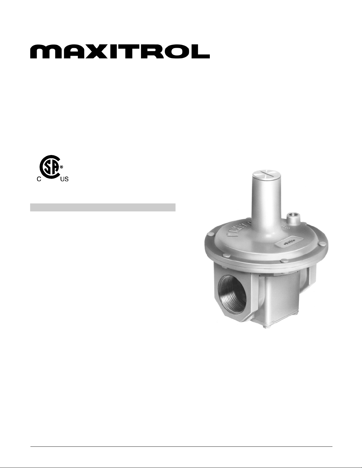
Gas Appliance Pressure Regulators
Straight-Thru-Flow Design
RV52, RV53, RV61, RV81, RV91, RV111, and RV131
1/2", 3/4", 1", 1¼", 1½", 2", 2½", 3" & 4"
design certified
Maximum Pressure
CSA Rated (except RV131) ............ 1/2 psi (35 mbar)
Maxitrol Tested*
RV52 & RV53 .................................. 1/2 psi (35 mbar)
RV61, RV81, RV91, & RV111 .......... 1 psi (70 mbar)
RV131 .............................................. 2 psi (140 mbar)
* Do not use if inlet pressure is more than 10 times
desired outlet pressure
EMERGENCY EXPOSURE LIMITS (Maxitrol Tested)
RV52 & RV53 .................................. 3 psi (210 mbar)
RV61, RV81, RV91 & RV111 ........... 5 psi (350 mbar)
RV131 .............................................. 15 psi (1050 mbar)
GAS CONTAINMENT EXPOSURE LIMITS*
RV 52 & RV53 ................................. 15 psi (1050 mbar)
RV61, RV81, RV91, RV111,
& RV131 .......................................... 25 psi (1750 mbar)
* Please note that internal damage may occur when
exposed to these pressures.
AMBIENT TEMPERATURE LIMITS
RV52, RV53, RV61, RV81,
RV91 & RV111 .................... -40° to 205° F (-40° to 96° C)
RV131 ................................. -40 to 125° F (-40 to 52° C)
........................................................
GASES: Suitable for application in natural, manufactured,
mixed gases, liquefied petroleum gases and LP gas-air mixture
piping systems.
S-T-F Series
© 2008, Maxitrol Company, All Rights Reserved
1
Page 2
Straight-Thru-Flow Design
RV series
All models except RV131 are CSA design certified for
1/2 psi rated pressure under the ANSI standard for gas
pressure regulators; and CSA listed to certify
compliance with nationally published safety,
construction, and performance standards.
They are main burner only, non-lockup type. They
should not be used as a line gas pressure regulator
ahead of low pressure controls. Use only where
downstream controls can operate at line pressure.
Refer to other Maxitrol sales bulletins for proper types.
RV52, RV53, RV61, RV81,
RV91, RV111, and RV131
FEATURES
• Greater accuracy—higher pressure drop capacity
• Outlet pressures available to 42” w.c.
• Available in full range of pipe sizes from 1/2"
to 4"
• All models tapped with NPT vent bosses
• CSA Design Certified (except RV131)
BENEFITS
• Unique conical valve design fills need of combining
good regulation with high capacity in low to
intermediate pressure range
• Allows more pressure drop to be assigned to piping
and valves—permits reduction in manifold size
• Provides accurate, sensitive regulation at inlet
pressures as low as 3” w.c.
• RV131 only, provides bonus benefits of high capacity
and good performance at pressures of 1 psi or higher
• Ease of installation and replacement
valves are coated with Teflon® for long life. Diaphragm
material is cut from the finest synthetic coated fabrics
available. All other parts are carefully specified corrosionresistant or plated material.
Pipe sizes of 1/2”, 3/4”, 1”, 1-1/4”, 1-1/2”, 2”, 2-1/2", 3”,
and 4” are available. Models through the 3" size are
threaded, the 4" RV131 is flanged.
The RV52, RV53, & RV61 are suitable for multipoise
mounting. The RV81, RV91, RV111, & RV131 are
recommended for normal horizontal position only.
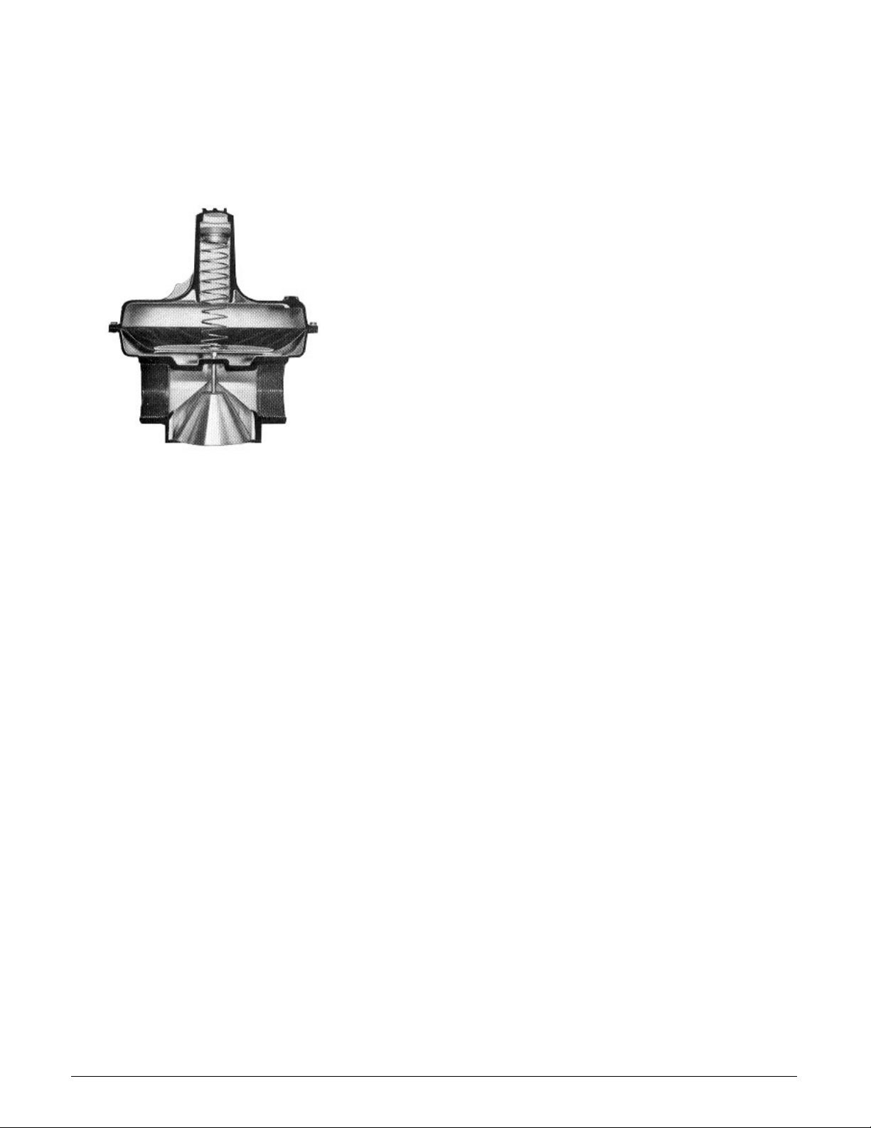
Maxitrol's original Straight-Thru-Flow design meets your
needs for high capacities at low inlet pressures. The
basic difference between S-T-F design and other type
regulators lies in the conical valve. The cone principal
permits gas to flow straight through the regulator
without changing directions. Frictional flow resistance is
reduced, resulting in greater capacity.
The improved flow pattern provides accurate sensitive
regulation at extremely low pressure differentials. The
ability of the regulator to handle large capacity
appliances with limited supply pressure offers a definite
advantage to designers of commercial and industrial
gas-fired equipment.
Models up to the three inch pipe size have high
strength pressure cast aluminum housings. The RV131
four inch model is of cast iron and steel construction.
RV61, RV81, RV91, RV111, & RV131 internal conical
© 2008, Maxitrol Company, All Rights Reserved
At the emergency exposure limits, there may be no
regulation, but all models will contain gas. They will suffer
no internal damage and will resume regulation when
normal pressure is restored.
Straight-Thru-Flow appliance regulators are intended for
use with all fuel gases, and may also be used with air or
other noncorrosive gases within their pressure limits.
Typical applications include all types of residential,
commercial and industrial gas-fired appliances and
equipment used on low pressure gas supply. See
Maxitrol’s ”Spring Selection Chart“ for part numbers, color
and size of springs.
Teflon is a registered trademark of DuPont Corporation.
NOTE: All Maxitrol appliance regulators should be installed in
accordance with Maxitrol’s “Safety Warning” bulletin.
2
Page 3

Capacities and Pressure Drop
CAPACITIES—expressed in CFH (m3/h)—0.64 sp gr gas
Model
Number and Pipe Size
RV52
1/ 2 x 1/ 2
3/ 4 x 3/ 4
A.G.A.
CSA
MAX
450
(12.7)
0.1 0.2 0. 3 0.4 0.5 0.6 0. 7 0. 8 0.9 1 2 3 4
151
214
262
(4.2)
(6.1)
(7.4)
302
(8.5)
Pressure DropÑinches w.c. (mbar)
338
(9.5)
370
(10.5)
400
(11.3)
427
(12.1)
453
(12.8)
478
(13.5)
676
(19.1)
828
(23.4)
956
(27.1)
RV53
RV61
RV81
RV91
RV111
RV131 4 x 4 --
3/ 4 x 3/ 4
1 x 1
1 x 1
1- 1/ 4 x 1 -1/ 4
1- 1/ 4 x 1 -1/ 4
1- 1/ 2 x 1 -1/ 2
2 x 2
2- 1/ 2 x 2 -1/ 2
2- 1/ 2 x 2 -1/ 2
3 x 3
710
(20.1)
1100
(31.1)
2500
(70.8)
3275
(92.7)
7500
(212)
217
(6.1)
379
(10.7)
780
(22.1)
1212
(34.3)
2742
(78)
4734
(134)
306
(8.6)
536
(15.1)
1102
(31.2)
1714
(48.5)
3878
(110)
6695
(190)
375
(10.6)
675
(19.1)
1350
(38.2)
2100
(59.4)
4750
(134)
8200
(232)
433
(12.2)
759
(21.5)
1559
(44.1)
2424
(68.6)
5485
(155)
9468
(268)
484
(13.7)
848
(24)
1743
(49.5)
2711
(76.7)
6132
(175)
10586
(300)
Sizing Instructions
In order to select the proper size regulator, you must know
the available inlet pressure, desired outlet pressure, and
the required maximum flow rate.
Example No. 1—To select a regulator of ample capacity to
handle flow.
KNOWN:
Pipe size 2-1/2", flow rate 8,000 CFH (0.64 sp gr), inlet
pressure 9" w.c., desired outlet pressure 5" w.c.
530
573
612
650
(15)
929
(26.3)
1909
(54)
2969
(84.1)
6718
(190)
11596
(328)
(16.2)
1004
(28.4)
2062
(58.4)
3208
(90.8)
7256
(205)
12525
(354)
(17.3)
1073
(30.4)
2204
(62.4)
3429
(97.1)
7757
(219)
13390
(380)
(18.4)
1138
(32.2)
2339
(66.2)
3637
(103)
8227
(233)
14202
(402)
684
(19.3)
1200
(34.0)
2465
(69.8)
3834
(108)
8572
(243)
14971
(424)
968
(27.4)
1742
(49.3)
3485
(98.7)
5422
(153)
12134
(343)
21172
(600)
1185
(33.5)
2134
(60.4)
4269
(120)
6640
(188)
14862
(420)
25930
(734)
SOLUTION:
1. Check capacity Chart above for 4" regulator,
RV131.
2. Note that at a flow rate of 21,172 CFH the
pressure drop is 2" w.c.
3. Multiply this by two to obtain recommended
differential pressure (4" w.c.).
4. Subtract 4" differential pressure from 10" w.c.
inlet pressure to obtain maximum recommended
outlet pressure setting of 6" w.c.
1369
(38.7)
2464
(69.8)
4929
(139)
7668
(217)
17161
(486)
29942
(848)
SOLUTION:
1. Determine differential pressure available:
Inlet pressure 9" w.c.
Subtract outlet pressure - 5" w.c.
Available differential pressure 4" w.c.
2. When determining capacity Maxitrol
recommends that the pressure drop not exceed
1/2 of available differential pressure (1/2 of 4"
w.c. = 2" w.c.).
3. Check Capacity Chart to determine which
regulator has a pressure drop of 2" w.c. or less at
a flow rate of 8,000 CFH.
4. The RV111 meets these standards with a
flow rate of 12,134 CFH for the 2-1/2" pipe size at
2" w.c. pressure drop. The 2-1/2" RV91 flows
5422 CFH at 2" w.c. pressure drop. Therefore, the
RV111—2-1/2" is the correct regulator to use.
Example No. 2—To determine maximum recommended
operating outlet pressure.
KNOWN:
Pipe size 4", flow rate 21,000 CFH, inlet pressure
10" w.c.
Pressure Drop Chart
© 2008, Maxitrol Company, All Rights Reserved
3
Page 4

Dimensions and Spring Ranges
RV52 & 53
A
RV61
RV81 & 91
A
A
C
D
B
C
D
B
DIMENSIONS*—inches (millimeters)
Model &
Illustration
Number
RV52
RV53
RV61
RV81
RV91
2" pipe
RV91
2.5" pipe
RV111
RV131
Vent
Tap
1/8"
NPT
1/8"
NPT
1/8"
NPT
3/8"
NPT
1/2"
NPT
1/4"
NPT
3/4"
NPT
3/4"
NPT
Swing
Radius
3.6
(91)
3.9
(99)
4.8
(122)
6.4
(162)
8.5
(216)
8.3
(212)
11.5
(284)
18.2
(462)
ABCD
4.9
(124)
5.2
(132)
6.4
(164)
8.4
(213)
10.8
(275)
10.5
(267)
15.1
(373)
23.25
(590)
* Dimensions are to be used only as an aid in designing clearance for the valve.
Actual production dimensions may vary somewhat from those shown.
3.2
(81)
3.75
(95)
4.4
(111)
6
(153)
6.5
(165)
7.1
(181)
9
(229)
13.9
(353)
Call-Outs
3.25
(83)
3.9
(99)
5.4
(138)
7
(178)
9.1
(232)
9.1
(232)
13.4
(324)
18
(458)
1.25
(32)
1.3
(33)
1.6
(41)
2
(51)
2.3
(60)
2.4
(62)
3.5
(89)
5.1
(129)
C
RV111
RV131
C
D
C
D
D
B
A
B
A
SPRING SELECTION CHART—inches w.c. (mbar)
Model
Number
RV52
RV53
RV61
RV81
RV91
RV111
RV131
A.G.A. Cert ified Springs Other Springs Available
CSA
3 to 6
(7.5-15)
3 to 6
(7.5-15)
3 to 6
(7.5-15)
3 to 6
(7.5-15)
3 to 6
(7.5-15)
3 to 6
(7.5-15)
3 to 6
(7.5-15)
4-8
(10-20)
4-8
(10-20)
4-8
(10-20)
4-8
(10-20)
4-8
(10-20)
4-8
(10-20)
--
5-12
(12.5-30)
5-12
(12.5-30)
5-12
(12.5-30)
5-12
(12.5-30)
5-12
(12.5-30)
5-12
(12.5-30)
5-12
(12.5-30)
1-3.5
(2.5-9)
1-3.5
(2.5-9)
1-3.5
(2.5-9)
1-3.5
(2.5-9)
1-3.5
(2.5-9)
1-3.5
(2.5-9)
--
2-5
(5-12.5)
2-5
(5-12.5)
2-5
(5-12.5)
2-5
(5-12.5)
2-5
(5-12.5)
2-5
(5-12.5)
2-5
(5-12.5)
3-8
(7.5-20)
3-8
(7.5-20)
3-8
(7.5-20)
3-8
(7.5-20)
3-8
(7.5-20)
3-8
(7.5-20)
3-8
(7.5-20)
NOTE: The area within the heavy line indicates CSA certified springs.
4-12
(10-30)
4-12
(10-30)
-- --
4-12
(10-30)
4-12
(10-30)
4-12
(10-30)
4-12
(10-30)
B
-- -- -- --
-- -- -- --
5-15
(12.5-38)
5-15
(12.5-38)
5-15
(12.5-38)
--
10- 22
(25-55)
10- 22
(25-55)
10- 22
(25-55)
10- 22
(25-55)
10- 22
(25-55)
-- --
-- --
-- --
-- --
15- 30
(38-75)
20- 42
(50-105)
Maxitrol Company
23555 Telegraph Rd., PO Box 2230
Southfield, MI 48037-2230 U.S.A.
RVSTF_MS_EN_03.2008
Replaced MS2056
4
© 2008, Maxitrol Company,
All Rights Reserved
 Loading...