

Page 1
Gas Pressure reGulators
CataloG
rd
3
edition
Page 2
Service and installation must be performed by a trained/experienced service technician.
All products used with combustible gas must be installed and used strictly in accordance
with the instructions of the Original Equipment Manufacturer (OEM) and with all
applicable government codes and regulations, e.g. plumbing, mechanical, and electrical
codes and practices. Maxitrol products should be installed and operated in accordance
with Maxitrol Safety Warning Instructions.
Maxitrol Company is NOT responsible for any errors or omissions in reliance by anyone of
any information set forth in this catalog without additional reference to local requirements
and applicable ordinances or codes.
Other worldwide approvals and certifications available upon inquiry.
2
®
C
US
UA.TR.012-13
© 2017, Maxitrol Company. All Rights Reserved.
Page 3
Gas Pr essure reGul a tor Ca t aloG
Appliance Regulators
RV Series Appliance Regulators: Rubber Seat Poppet Design.....................................................4-9
RV Series Appliance Regulators: Straight-Thru-Flow Design...................................................10-13
325 Series Appliance Regulators: Lever Acting Design..........................................................14-17
R/RS Series Appliance Regulators: Balanced Valve Design......................................................18-21
210 Series Appliance Regulators: Balanced Valve Design....................................................22-31
RZ and 210Z Series Appliance Regulators: Zero Governor Design.........................................32-37
220 Series Appliance Regulators: Pilot Loaded Design..........................................................38-41
SR Series Appliance Regulators: Two-Stage Design..............................................................42-45
Line Regulators
325L Series Line Regulators for 2PSI: Lever Acting Design.....................................................46-49
325L Series Line Regulators for 5PSI: Lever Acting Design.....................................................50-55
Spring Selection Chart .............................................................................................................56-57
Sizing a Regulator .......................................................................................................................58-59
Accessories
Pressure Tap Connector...........................................................................................................61
Dust Cap................................................................................................................................61
Tamper Proof Seals..................................................................................................................61
Choosing a Vent Accessory.....................................................................................................62
Venting.......................................................................................................................60-61
Definitions .....................................................................................................................................63
Gas and Air Filters ...................................................................................................................64-67
3
Page 4
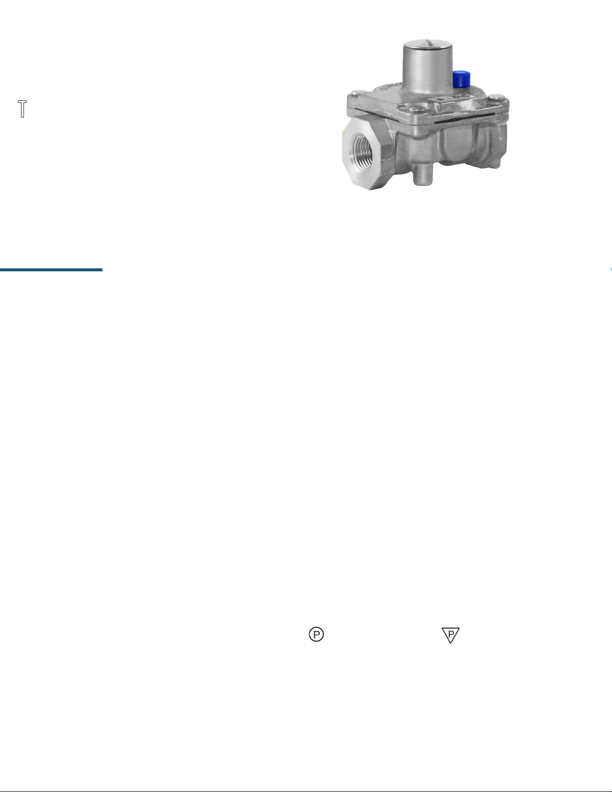
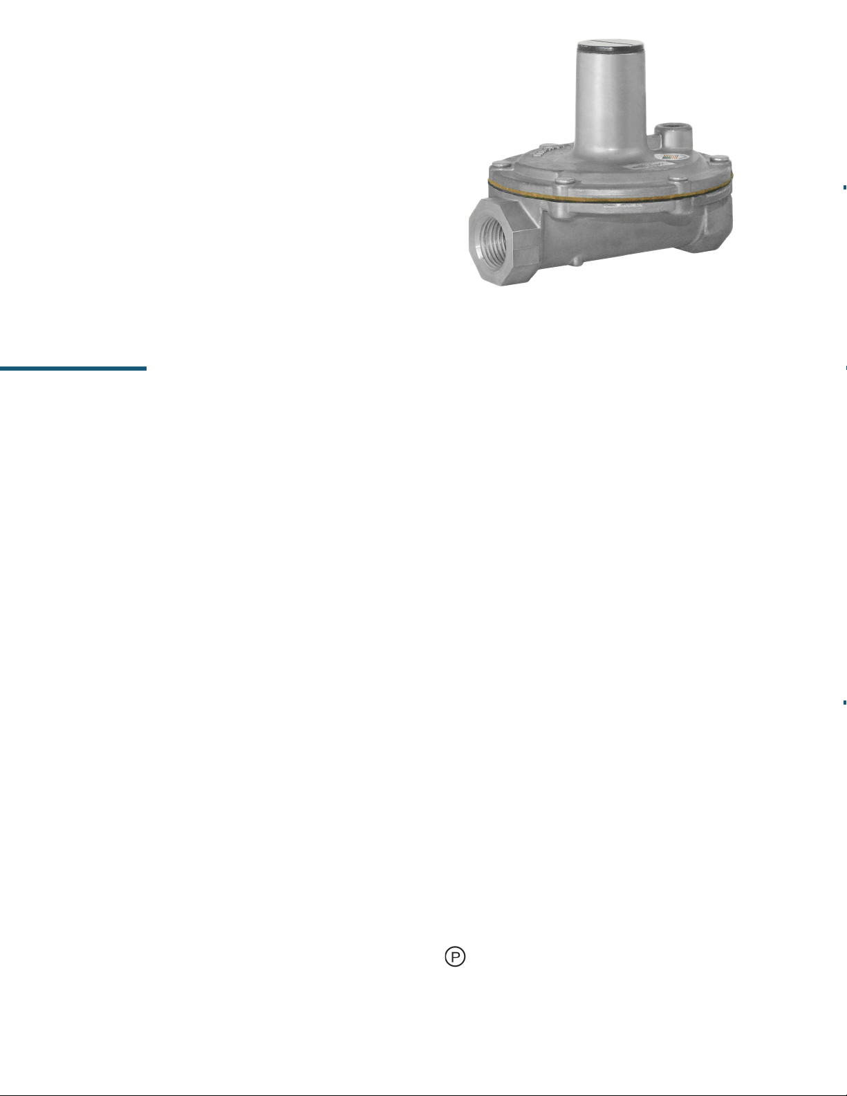
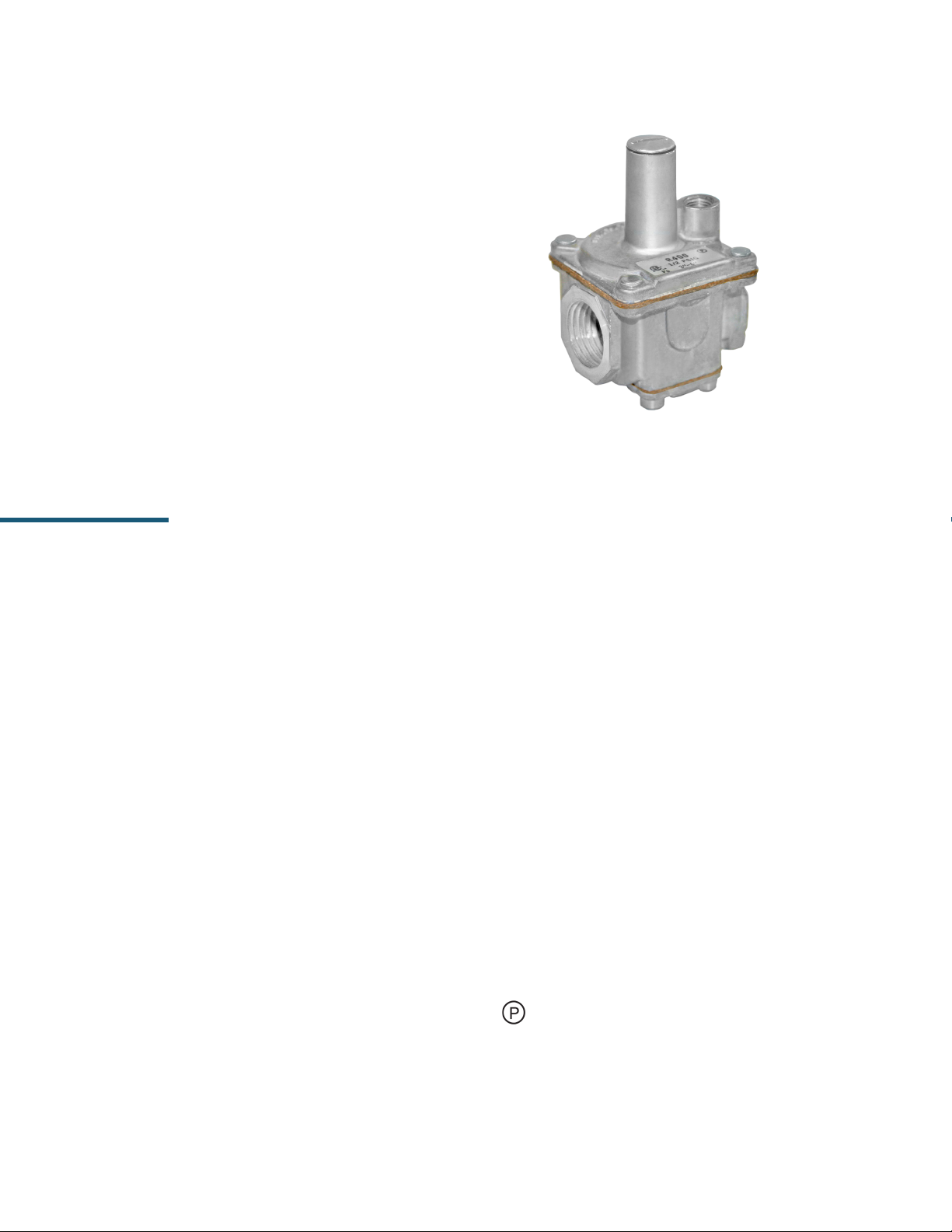
RV SERIES
Rubber Seat Poppet Design
The compact RV poppet regulators are designed primarily for main
burner and pilot load applications. Typical applications include
residential and commercial cooking appliances, barbecues, hearth
products, and pilot lines. Maxitrol rubber seat poppet models offer
the ultimate in design features and performance capabilities to
meet your specific appliance or utility requirements.
RV47
Specications
Pipe Sizes .....................................1/8” thru 3/4” threaded connections with NPT or ISO7-1 threads.
(Other connections available, please consult Maxitrol Company.)
Housing Material ..................... RV12, RV20, RV47, RV48, CV47: aluminum.
Mounting ................................. All models, with the exception of “D” sufx models, are suitable for multi-positional mounting.
Other than upright position will result in a slight difference in outlet pressure. “D” sufx
models are to be mounted upright only. If ball check vent limiting device is installed, mount in
an upright position only.
NOTE: All Maxitrol gas pressure regulators should be installed and operated in accordance
with Maxitrol Safety Warning Instructions (see GPR_MI_EN.ES or GPR_CSA_MI_EN.FR).
Certications ........................... RV Series: ANSI Z21.18/CSA 6.3 Gas Appliance Pressure Regulators.
CV47 Series: ANSI Z21.78/CSA 6.20 Combination Gas Controls for Gas Appliances.
Gas Types (RV Series) ............... Suitable for natural, manufactured, mixed gases, liqueed petroleum gases, and
LP gas-air mixtures.
Gas Types (CV47 Series) ........... Suitable for natural or liqueed petroleum gases.
Rated Inlet Pressure ................. 1/2 psi (3.4 kPa)
Emergency Exposure Limits ...... 2.5 psi (17.2 kPa)
Ambient Temperature Ranges ... RV20, RV47, RV48, CV47: 32° to 225°F (0° to 107°C)
RV12: -40° to 225°F (-40° to 107°C)
RV12T: -40° to 275°F (-40° to 135°C)
RV20T: -40° to 300°F (-40° to 148°C)
RV48T: 32° to 275°F (0° to 135°C)
Minimum Regulation ................ Suitable for pilot ow applications. (Circle P) (0.15 CFH NG), (Delta P)
(0.50 CFH NG), None (1.5 CFH NG), N Models (3 CFH NG).
4
© 2017, Maxitrol Company. All Rights Reserved.
Page 5
APPLIANCE REGULATORS
C
US
®
UA.TR.012-13
Model Designations
Models having a sufx letter or a combination of sufx letters listed below indicates the design modications described.
A ............Limited spring adjustment (RV47A & CV47A**, short stack*).
C ............Convertible regulators***; preset to deliver outlet pressures for either natural or LP gases.
(RV20, RV47, RV48, CV47)
D ............Integral ball check limiting device; permits higher maximum individual load.
(see Capacities and Pressure Drop, page 6)
E .............Excessive pressure rated.
F .............Factory-set; xed/non-adjustable regulator.
I .............Left side integral manual valve; outlet faces main inlet (CV47).
L .............Integral vent limiting orice as the breather hole - with dust cap.
M ...........B.S.P. - PL parallel thread - conforms to ISO 7-1, where pressure tight joints are made on the threads.
N ............Internal by-pass orice to prevent lockup. Main burner only (RV20, RV47, RV48, CV47).
R ............Right side+ integral manual valve; outlet faces main outlet (CV47).
SR ...........Side pressure tap; right side+ 1/8” NPT (RV20, RV47, RV48, CV47I).
S .............Side pressure tap; left side+ 1/8” NPT (RV20, RV47, RV48, CV47R).
T.............Higher ambient temperature range.
V ............Threaded vent connector, 5/16-24 for 1/8” tubing connection (RV20) - with dust cap.
* Short stack models have an adjustment range of less than 2” w.c. (0.5 kPa); these models are advantageous
where installation must be made in a limited space.
** CV47 is best described as a RV47 with an extra regulated outlet. This outlet contains an integral manual valve
located on the valve body’s side.
*** Convertible regulators are designed to deliver either of two xed outlet pressures for natural or LP gases.
RV20C: NAT GAS: 4.0” w.c. (1.0 kPa); LP: 10” w.c. (2.5 kPa)
RV47C, RV48C, CV47C: NAT GAS: 4.0”, 5.0” or 6.0” w.c. (1.0, 1.3, or 1.5 kPa); LP: 10” or 11” w.c. (2.5 or
2.8 kPa)
+ Left and right is determined when viewing regulator from outlet side with stack up.
NOTE: The RV48 model may be used with either a 12A04 ball check device, or a 12A06 xed orice vent limiting device.
See page 62 for vent accessory options.
5
Page 6
RV SERIES
Rubber Seat Poppet Design
Capacities and Pressure Drop
Capacities expressed in Btu/h (m3/h) @ 0.64 sp gr gas
Range of Regulation Individual Load
Main Burner
30,000 (0.85)
125,000 (3.5) 90,000 (2.5) 40,000 (1.1) 125,000 (3.5)
125,000 (3.5) 125,000 (3.5) 40,000 (1.1) 125,000 (3.5)
400,000 (11.3)
Main Burner
& Pilot
25,000 (0.71)
275,000
275,000
(7.8) Nat
(3.1) LP
Fixed Orice
20,000 (0.56) ---
40,000 (1.1) 160,000 (4.5)
40,000 (1.1) 160,000 (4.5)
Ball Check
Device
Model Pipe Size
RV12
RV20
RV20C
CV47
RV47
CV47A or C
RV47A or C
RV48
RV48C
1/8” x 1/8”* 14,800 (0.42)
3/16” x 3/16”Loxit 8,800 (0.25) 15,000 (0.43)
1/4” x 1/4”
3/8” x 3/8”*
1/4” x 1/4”
3/8” x 3/8”
3/8”x 3/8” 55,000 (1.5)
1/2” x 1/2”* 60,000 (1.7)
3/8” x 3/8” 55,000 (1.5)
1/2” x 1/2” 60,000 (1.7)
1/2” x 1/2” 130,000 (3.7) 230,000 (6.5) 230,000 (6.5)
3/4” x 3/4” 150,000 (4.2) 250,000 (7.1) 250,000 (7.1)
1/2” x 1/2” 130,000 (3.7)
3/4” x 3/4” 150,000 (4.2)
Pressure Drop
@ 0.3” w.c.
or (0.07 kPa)
30,000 (0.85) 65,000 (1.84) 50,000 (1.4) 30,000 (0.85) ---
30,000 (0.85) 75,000 (2.11) 50,000 (1.4) 15,000 (0.42) ---
*Also available as Loxit connection.
NOTE: CSA maximum capacities vary with spring range and pipe size. Please contact Maxitrol directly for CSA maximums.
Minimum main burner regulation capacity for all models (except “N”) is 150 Btu/hr (0.0042 m3/h). See pages 58-59
for Regulator Sizing Requirements and Examples.
6
© 2017, Maxitrol Company. All Rights Reserved.
Page 7
Spring Selection Chart: inches w.c. (kPa)
Model Available Springs
APPLIANCE REGULATORS
RV12
RV20
RV47
CV47
RV48
1.5 to 3*
(0.37 to 0.75)
Brown
1 to 3.5*
(0.25 to 0.9)
Brown
1 to 3.5*
(0.25 to 0.9)
Brown
1 to 3.5*
(0.25 to 0.9)
Brown
2.8 to 5.2
(0.69 to 1.3)
Plated
2.8 to 5.2
(0.69 to 1.3)
Plated
2.8 to 5.2
(0.69 to 1.3)
Plated
3.0 to 6.0
(0.75 to 1.5)
Plated
---
---
3.8 to 4.3
(0.95 to 1.08)
Black
---
4 to 8
(1 to 2)
Orange
4 to 8
(1 to 2)
Orange
4 to 8
(1 to 2)
Orange
4 to 8
(1 to 2)
Orange
*Uncertied Spring
**Certied at inlet pressure of 2 psi
Model Available Springs
RV20CL
4 / 10
(1 / 2.5)
--- --- --- --- ---
--- --- --- ---
--- --- --- ---
4 to 12*
(1 to 3)
Violet
--- ---
4.7 to 5.3
(1.18 to 1.33)
Green
---
5 to 12
(1.25 to 3)
Blue
5.6 to 6.4
(1.4 to 1.6)
Red
---
6 to 10
(1.5 to 2.5)
Red
6 to 10
(1.5 to 2.5)
Red
6 to 10
(1.5 to 2.5)
Red
6 to 10
(1.5 to 2.5)
Red
8 to 12
(2 to 3)
Blue
8 to 12
(2 to 3)
Blue
8 to 12
(2 to 3)
(2.42 to 2.83)
Blue
--- ---
---
9 to 12**
(2.25 to 3)
Plated
9.7 to 11.3
Plated
RV47CL
CV47CL
RV48C
4 / 10
(1 / 2.5)
4 / 10
(1 / 2.5)
4 / 10
(1 / 2.5)
4 / 11
(1 / 2.75)
4 / 11
(1 / 2.75)
4 / 11
(1 / 2.75)
5 / 10
(1.25 / 2.5)
5 / 10
(1.25 / 2.5)
5 / 10
(1.25 / 2.5)
5 / 11
(1.25 / 2.75)
5 / 11
(1.25 / 2.75)
5 / 11
(1.25 / 2.75)
NOTE: See pages 56-57 for complete Spring Selection Chart.
6 / 10
(1.5 / 2.5)
6 / 10
(1.5 / 2.5)
6 / 10
(1.5 / 2.5)
6 / 11
(1.5 / 2.75)
6 / 11
(1.5 / 2.75)
6 / 11
(1.5 / 2.75)
7
Page 8
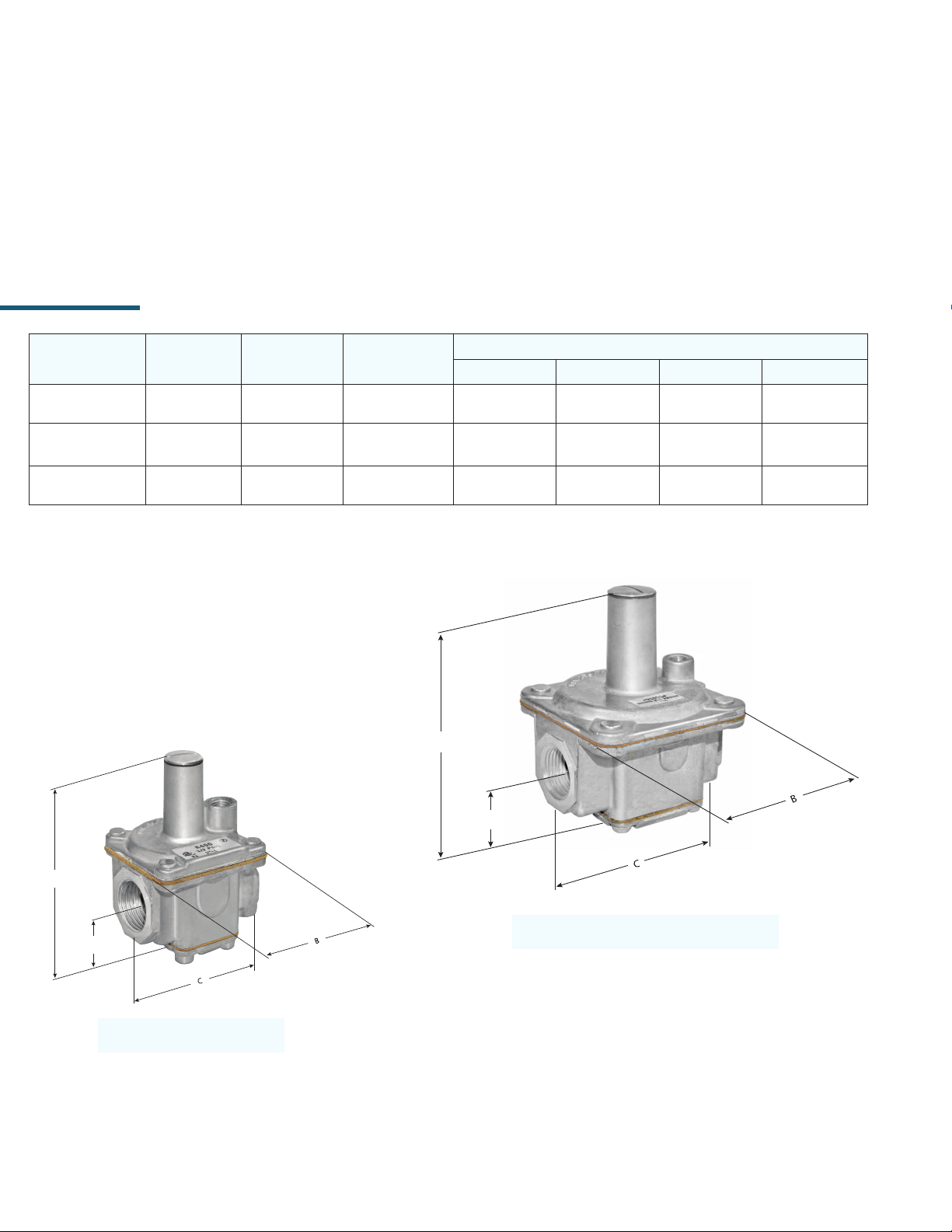
RV SERIES
Rubber Seat Poppet Design
Dimensions
0.4”
(10 mm)
0.5”
(13 mm)
0.6”
(16 mm)
0.8”
(19 mm)
Dimensions
(43 mm)
(61 mm)
(75 mm)
(86 mm)
Model Pipe Size Vent Swing Radius
RV12
RV20 1/4”, 3/8”
RV47
CV47
RV47A
CV47A
RV48 1/2”, 3/4”
1/8”
3/16”Loxit
3/8”, 1/2”
12A04 or 12A06 vent limiting
Integral Vent
Limiting Orice “L”
Integral Vent
Limiting Orice “L”
or 5/16-24 “V”
Integral Vent
Limiting Orice “D” or “L”
sufx
Integral “L” or 1/8” NPT,
device
1.4”
(35 mm)
1.6”
(41 mm)
1.9”
(48 mm)
1.6”
(41 mm)
2”
(51 mm)
A B C D
1.7”
(43 mm)
2.1”
(54 mm)
2.5”
(64 mm)
2.3”
(57 mm)
2.8”
(70 mm)
NOTE: Dimensions are maximums and to be used only as an aid in designing clearance for the valve.
Actual production dimensions may vary somewhat from those shown.
A
B
A
B
1.7”
2.4“
2.9”
3.4”
1.4”
(35 mm)
1.8”
(45 mm)
2.3”
(57 mm)
3”
(76 mm)
A
B
8
RV12
RV20 RV47, RV47A
A
B
CV47, CV47A RV48
A
B
© 2017, Maxitrol Company. All Rights Reserved.
Page 9
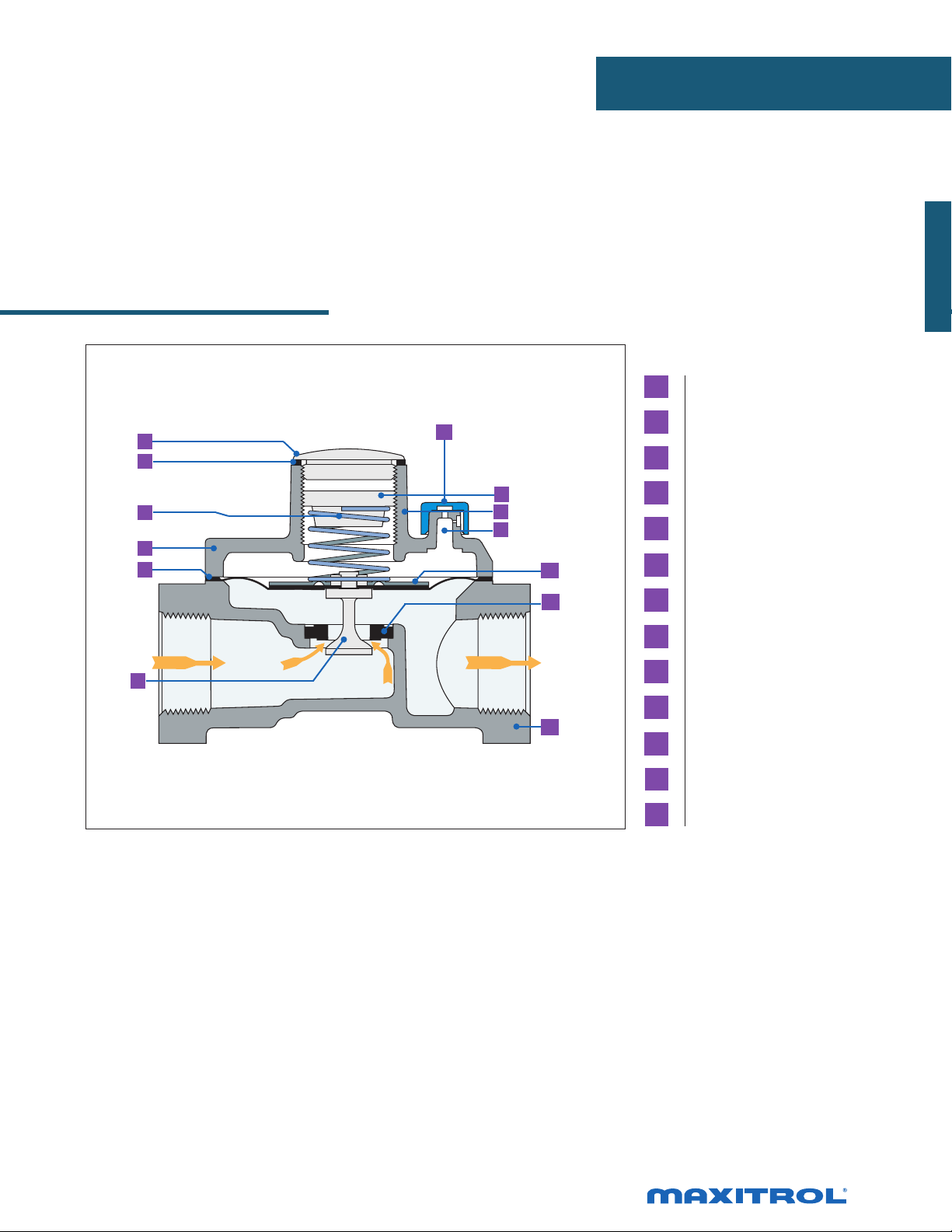
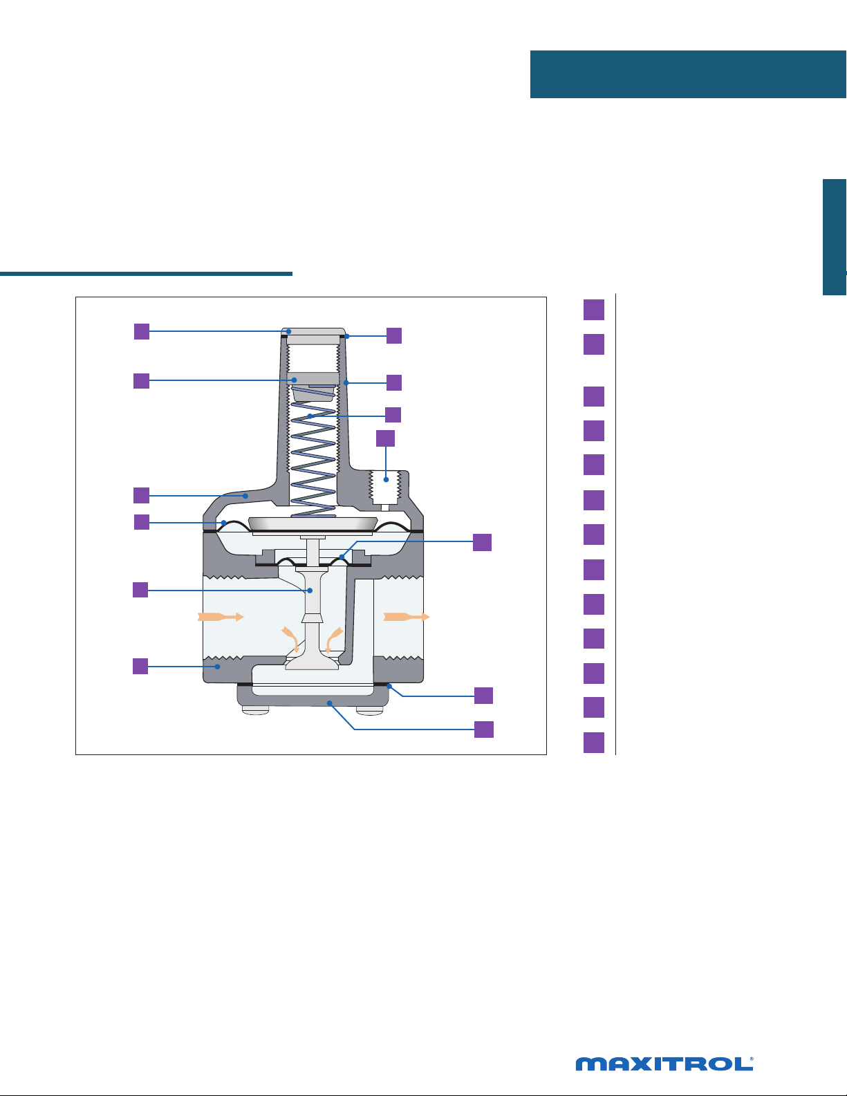
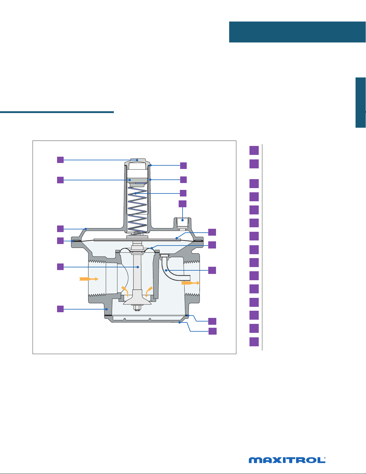
Rubber Seat Poppet Design
APPLIANCE REGULATORS
1 Seal Cap
1
2
3
4
5
13
7
8
9
10
11
2 Seal Cap Gasket
3 Spring
4 Top Housing
5 Diaphragm
6 Stem & Valve
7 Adjusting Screw
8 Stack
6
9 Vent
10 Diaphragm Plate
12
11 Rubber Seat
12 Bottom Housing
13 Dust Cap
NOTE: Diagrams are graphical representations only and may differ from actual product.
9
Page 10
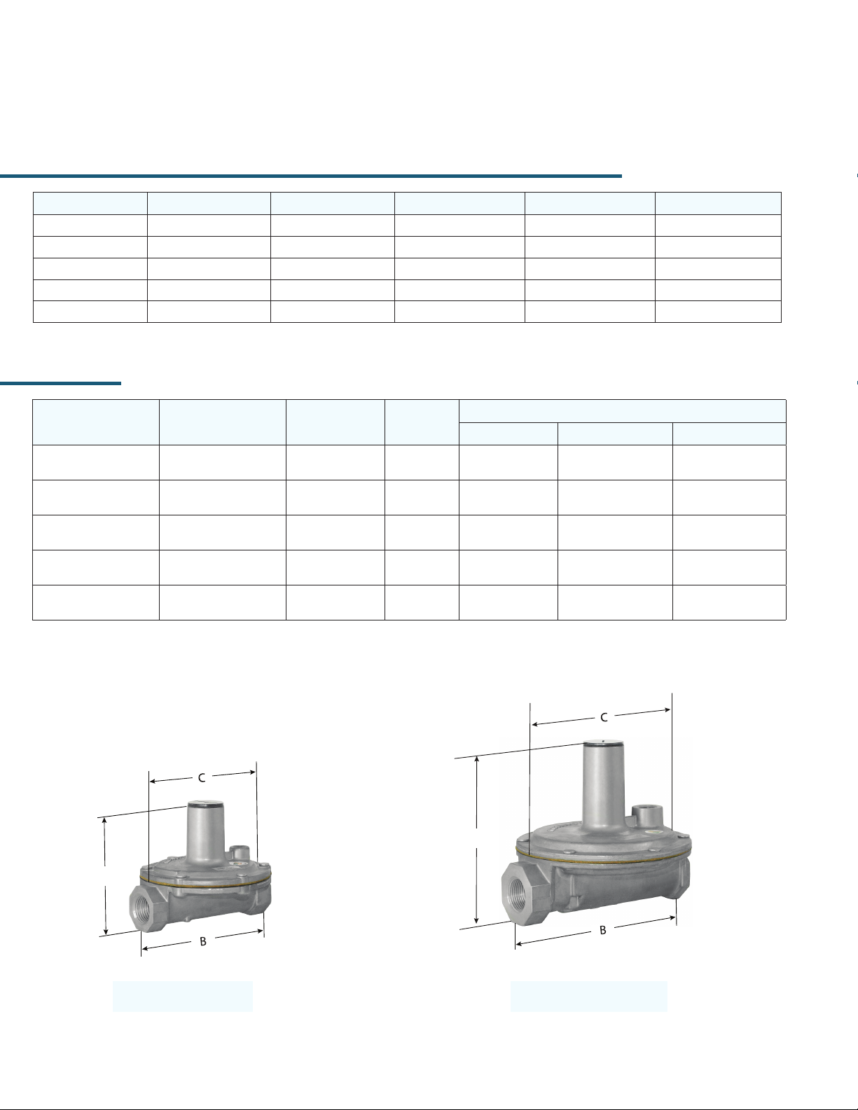
RV SERIES
Straight-Thru-Flow Design
Maxitrol’s original straight-thru-ow (STF) design regulators
are non-lockup type regulators for high capacities at low inlet
pressures. The difference between STF design and other type
regulators is the conical valve. The cone principal permits gas to
ow straight through the regulator without changing directions.
Frictional ow resistance is reduced, resulting in greater
capacity. An improved ow pattern provides accurate, sensitive
regulation at extremely low pressure differentials. Typical
applications include residential, commercial, and industrial
gas-red appliances and equipment used on low or medium
pressure gas supplies.
Specications
Pipe Sizes ................................. 1/2” to 3” threaded connections with NPT or ISO7-1 threads. 4” 150lb. ange (RV131 only).
RV81
Housing Material .....................RV52, RV53, RV61, RV81, RV91, RV111: aluminum; RV131: cast iron.
Mounting .................................RV52, RV53, RV61 are suitable for multi-positional mounting. If ball check vent limiting
device is installed, mount in an upright position only. RV81, RV91, RV111, RV131, upright
position only.
NOTE: All Maxitrol gas pressure regulators should be installed and operated in accordance
with Maxitrol Safety Warning Instructions (see GPR_MI_EN.ES or GPR_CSA_MI_EN.FR).
Certications ...........................RV52, RV53, RV61, RV81, RV91, RV111: ANSI Z21.18/CSA6.3 Gas Appliance Pressure
Regulators.
Gas Types .................................Suitable for natural, manufactured, mixed gases, liqueed petroleum gases, and LP gas-air
mixtures.
Rated Inlet Pressure .................CSA Certied: RV52, RV53, RV61, RV81, RV91, RV111: 1/2 psi (3.4 kPa)
Maxitrol Tested* .......................RV52, RV53: 1/2 psi (3.4 kPa)
RV61, RV81, RV91, RV111: 1 psi (6.9 kPa)
RV131: 2 psi (13.8 kPa)
*Do not use if inlet pressure is more than 10 times desired outlet pressure.
Emergency Exposure Limits ......RV52, RV53: 3 psi (21 kPa)
RV61, RV81, RV91, RV111: 5 psi (34 kPa)
RV131: 15 psi (103 kPa)
Gas Containment Limits ........... RV52, RV53: 15 psi (103 kPa)
RV61, RV81, RV91, RV111, RV131: 25 psi (172 kPa)
NOTE: Internal damage may occur when exposed to these pressures.
Ambient Temperature Ranges ...RV52, RV53, RV61, RV81, RV91, RV111: -40° to 205°F (-40° to 96°C)
RV131: -40° to 125°F (-40° to 52°C)
Minimum Regulation ................RV52, RV53: 20 CFH; RV61: 25 CFH; RV81, RV91: 50 CFH; RV111, RV131: 250 CFH.
Expressed in CFH @ 0.64 sp gr gas.
10
© 2017, Maxitrol Company. All Rights Reserved.
Page 11
Capacities and Pressure Drop
C
US
®
Capacities expressed in CFH (m3/h) @ 0.64 sp gr gas
Model
RV52
RV53
RV61
RV81
RV91
RV111
RV131 4” x 4” ---
Pipe
Size
1/2” x 1/2”
3/4” x 3/4”
3/4” x 3/4”
1” x 1”
1” x 1”
1 1/4” x 1 1/4”
1 1/4” x 1 1/4”
1 1/2” x 1 1/2”
2” x 2”
2 1/2” x 2 1/2”
2 1/2” x 2 1/2”
3” x 3”
CSA
MAX
450
(12.7)
690
(19.5)
900
(24.5)
2500
(70.8)
3275
(92.7)
7500
(212)
0.1
(0.02)
151
(4.2)
217
(6.1)
379
(10.7)
780
(22.1)
1212
(34.3)
2742
(78.0)
4734
(134)
0.2
(0.04)
214
(6.1)
306
(8.6)
536
(15.1)
1102
(31.2)
1714
(48.5)
3878
(110)
6695
(190)
0.3
(0.07)
262
(7.4)
375
(10.6)
675
(19.1)
1350
(38.2)
2100
(59.4)
4750
(134)
8200
(232)
0.4
(0.10)
302
(8.5)
433
(12.2)
759
(21.5)
1559
(44.1)
2424
(68.6)
5485
(155)
9468
(268)
APPLIANCE REGULATORS
Pressure Drop - inches w.c. (kPa)
0.5
(0.12)
338
(9.5)
484
(13.7)
848
(24.0)
1743
(49.5)
2711
(76.7)
6132
(175)
10586
(300)
0.6
(0.15)
370
(10.5)
530
(15)
929
(26.3)
1909
(54.0)
2969
(84.1)
6718
(190)
11596
(328)
0.7
(0.17)
400
(11.3)
573
(16.2)
1004
(28.4)
2062
(58.4)
3208
(90.8)
7256
(205)
12525
(354)
0.8
(0.20)
427
(12.1)
612
(17.3)
1073
(30.4)
2204
(62.4)
3429
(97.1)
7757
(219)
13390
(380)
0.9
(0.22)
453
(12.8)
650
(18.4)
1138
(32.2)
2339
(66.2)
3637
(103)
8227
(233)
14202
(402)
1.0
(0.25)
478
(13.5)
684
(19.3)
1200
(34.0)
2465
(69.8)
3834
(108)
8572
(243)
14971
(424)
UA.TR.012-13
(19.1)
(27.4)
(49.3)
(98.7)
12134
21172
2.0
(0.5)
676
968
1742
3485
5422
(153)
(343)
(600)
3.0
(0.75)
828
(23.4)
1185
(33.5)
2134
(60.4)
4269
(120)
6640
(188)
14862
(420)
25930
(734)
4.0
(1.0)
956
(27.1)
1369
(38.7)
2464
(69.8)
4929
(139)
7668
(217)
17161
(486)
29942
(848)
NOTE: See pages 58-59 for Regulator Sizing Requirements and Examples.
Spring Selection Chart: inches w.c. (kPa)
Model CSA Certied Springs Other Springs Available
RV52
RV53
RV61
RV81
RV91
RV111
RV131
3 to 6
(0.75 to 1.5)
Plated
3 to 6
(0.75 to 1.5)
Plated
3 to 6
(0.75 to 1.5)
Plated
3 to 6
(0.75 to 1.5)
Plated
3 to 6
(0.75 to 1.5)
Plated
3 to 6
(0.75 to 1.5)
Plated
3 to 6
(0.75 to 1.5)
Plated
4 to 8
(1 to 2)
Orange
4 to 8
(1 to 2)
Orange
4 to 8
(1 to 2)
Orange
4 to 8
(1 to 2)
Orange
4 to 8
(1 to 2)
Orange
4 to 8
(1 to 2)
Orange
---
5 to 12
(1.25 to 3)
Blue
5 to 12
(1.25 to 3)
Blue
5 to 12
(1.25 to 3)
Blue
5 to 12
(1.25 to 3)
Blue
5 to 12
(1.25 to 3)
Blue
5 to 12
(1.25 to 3)
Blue
5 to 12
(1.25 to 3)
Blue
1 to 3.5
(0.25 to 0.9)
Brown
1 to 3.5
(0.25 to 0.9)
Brown
1 to 3.5
(0.25 to 0.9)
Brown
1 to 3.5
(0.25 to 0.9)
Brown
1 to 3.5
(0.25 to 0.9)
Brown
1 to 3.5
(0.25 to 0.9)
Brown
---
2 to 5
(0.5 to 1.25)
Plated
2 to 5
(0.5 to 1.25)
Plated
2 to 5*
(0.5 to 1.25)
Plated
2 to 5
(0.5 to 1.25)
Plated
2 to 5
(0.5 to 1.25)
Plated)
2 to 5
(0.5 to 1.25)
Plated
2 to 5
(0.5 to 1.25)
Plated
3 to 8
(0.75 to 2)
Pink
3 to 8
(0.75 to 2)
Pink
3 to 8
(0.75 to 2)
Pink
3 to 8
(0.75 to 2)
Pink
3 to 8
(0.75 to 2)
Pink
3 to 8
(0.75 to 2)
Pink
3 to 8
(0.75 to 2)
Pink
4 to 12
(1 to 3)
Violet
4 to 12
(1 to 3)
Violet
--- ---
4 to 12
(1 to 3)
Violet
4 to 12
(1 to 3)
Violet
4 to 12
(1 to 3)
Violet
4 to 12
(1 to 3)
Violet
(1.25 to 3.7)
(1.25 to 3.7)
(1.25 to 3.7)
--- --- --- ---
--- --- --- ---
5 to 15
Green
5 to 15
Green
5 to 15
Green
---
10 to 22
(2.5 to 5.5)
Red
10 to 22
(2.5 to 5.5)
Red
10 to 22
(2.5 to 5.5)
Red
10 to 22
(2.5 to 5.5)
Red
10 to 22
(2.5 to 5.5)
Red
--- ---
--- ---
--- ---
--- ---
15 to 30
(3.7 to 7.5)
Yellow
20 to 42
(5 to 10.5)
Black
NOTE: The area within the heavy line indicates CSA certied springs. See pages 56-57 for complete Spring Selection Chart.
* The 2 to 5 inches w.c. (0.5 to 1.25 kPa) spring is also CSA certied for the RV61
11
Page 12

RV SERIES
Straight-Thru-Flow Design
Dimensions
Model Pipe Size
RV52 1/2”, 3/4” 1/8” NPT 3.6” (91 mm) 4.9” (124 mm) 3.2” (81 mm) 3.3” (83 mm) 1.3” (32 mm)
RV53 3/4”, 1” 1/8” NPT 3.9” (99 mm) 5.2” (132 mm) 3.8” (95 mm) 3.9” (99 mm) 1.3” (33 mm)
RV61 1”, 1 1/4” 1/8” NPT 4.8” (122 mm) 6.4” (164 mm) 4.4” (111 mm) 5.4” (138 mm) 1.6” (41 mm)
RV81 1 1/4”, 1 1/2” 3/8” NPT 6.4” (162 mm) 8.4” (213 mm) 6” (153 mm) 7” (178 mm) 2” (51 mm)
2” 1/2” NPT 8.5” (216 mm) 10.8” (275 mm) 6.5” (165 mm) 9.1” (232 mm) 2.3” (60 mm)
RV91
2 1/2” 1/4” NPT 8.3” (212 mm) 10.5” (267 mm) 7.1” (181 mm) 9.1” (232 mm) 2.4” (62 mm)
RV111 2 1/2”, 3” 3/4” NPT 11.5” (284 mm) 15.1” (373 mm) 9” (229 mm) 13.4” (324 mm) 3.5” (89 mm)
RV131 4” 3/4” NPT 18.2” (462 mm) 23.3” (592 mm) 13.9” (353 mm) 18” (457 mm) 5.1” (130 mm)
Vent
Connection
Swing Radius
A B C D
Dimensions
NOTE: Dimensions are maximums and to be used only as an aid in designing clearance for the valve.
Actual production dimensions may vary somewhat from those shown.
A
D
A
D
12
A
RV61RV52, RV53
D
A
RV131
D
RV81, RV91
A
D
RV111
© 2017, Maxitrol Company. All Rights Reserved.
Page 13
Straight-Thru-Flow Design
APPLIANCE REGULATORS
1 Welch Plug/Seal Cap
1
2
3
4
5
6
7
8
9
10
11
12
13
14
2 Vibration Resistant
Adjusting Screw
3 Top Housing
4 Diaphragm
5 Stem
6 Bottom Housing
7 Seal Cap Gasket
8 Stack
9 Spring
10 Vent Connection
11 Diaphragm Plates
12 Valve
13 Bottom Plate Gasket
14 Bottom Plate
NOTE: Diagrams are graphical representations only and may differ from actual product.
13
Page 14
325 SERIES
Lever Acting Design
Maxitrol’s 325 Series pounds to inches regulators are for use on
residential, commercial, and industrial applications.
The 325 Series features a high leverage valve linkage assembly
to deliver positive dead-end lockup. The regulators are capable
of precise control from full ow down to pilot ow.
325-3
Specications
Pipe Sizes ..................................... 3/8” to 2” threaded connections with NPT or ISO7-1 threads.
Housing Material ......................... 325-3, 325-5, 325-7A, 325-9, 325-11: aluminum.
Mounting ..................................... Suitable for multi-positional mounting. If ball check vent limiting device is installed, mount
in an upright position only.
NOTE: All Maxitrol gas pressure regulators should be installed and operated in accordance
with Maxitrol Safety Warning Instructions (see GPR_MI_EN.ES or GPR_CSA_MI_EN.FR).
Certications ............................... 325-3, 325-5: ANSI Z21.18/CSA 6.3 Gas Appliance Pressure Regulators.
Gas Types ..................................... Suitable for natural, manufactured, mixed gases, liqueed petroleum gases, and LP gas-air
mixtures.
Rated Inlet Pressure ..................... CSA Certied: 325-3, 325-5: 2 psi (13.8 kPa), 5 psi (34.5 kPa)
Maxitrol Tested ............................ 325-3, 325-5, 325-7A, 325-9: 10 psi (69 kPa)
With Vent Limiter 12A09, 12A39, or 12A49 Installed:
325-3, 325-5, 325-7A, 325-9: 5 psi (34.5 kPa) - Natural, 2 psi (13.8 kPa) - LP
Emergency Exposure Limits .......... 65 psi (450 kPa) (inlet side only)
Maximum Individual Load ........... Largest single appliance served by the regulator: 325-3: 100,000 Btu/h;
325-5: 325,000 Btu/h; 325-7A: 1,250,000 Btu/h, 325-9: 2,250,000 Btu/h; 325-11:
4,500,000 Btu/h
Capacity ......................................Total load of multiple appliances combined: 325-3: 150,000 Btu/h;
..................................................... 325-5: 325,000 Btu/h; 325-7A: 1,250,000 Btu/h; 325-9: 2,250,000 Btu/h;
325-11: 4,500,000 Btu/h
NOTE: Capacities are used to determine the maximum multiple appliance load. The
largest single appliance served by the regulator should not exceed the maximum
individual load specied above.
Ambient Temperature Ranges .......-40 to 205°F (-40 to 96°C)
Minimum Regulation .................... Suitable for pilot ow applications. (Circle P) (0.15 CFH NG), None (1.5 CFH NG).
14
© 2017, Maxitrol Company. All Rights Reserved.
Page 15
APPLIANCE REGULATORS
C
US
®
UA.TR.012-13
Capacities: based on 1” w.c. pressure drop, from set point**
Capacities expressed in CFH (m3/h) @ 0.64 sp gr gas
Model Pipe Size
325-3
325-5
325-7A
325-9
325-11
NOTE: Maximum Individual Load: 325-3(B) is 100 CFH (2.8 m3/h); 325-5(B) is 325 CFH (9.2 m3/h); 325-7A(B) is 1250 CFH (35.4 m3/h); 325-9(B) is 2250 CFH (63.7).
Approval based on use as an appliance regulator. **Set points (in CFH): 325-3(B) = 50; 325-5(B) = 150; 325-7A(B) = 500; 325-9(B) = 1000; 325-11(B) = 2000.
See pages 58-59 for Regulator Sizing Requirements and Examples.
3/8” x 3/8”
1/2” x 1/2”
1/2” x 1/2”
3/4” x 3/4”
1” x 1”
1 1/4” x 1 1/4”
1 1/2” x 1 1/2”
1 1/2” x 1 1/2”
2” x 2”
1 1/2” x 1 1/2”
2” x 2”
Outlet Pressure
Set Point
4.0” w.c. (1.0 kPa) 150 (4.2) 160 (4.5) 190 (5.4) 220 (6.2) 220 (6.2) 300 (8.5) 320 (9.1)
7.0” w.c. (1.7 kPa) 150 (4.2) 120 (3.4) 150 (4.2) 180 (5.1) 220 (6.2) 290 (8.2) 320 (9.1)
10.0” w.c. (2.5 kPa) 150 (4.2) 100 (2.8) 120 (3.4) 150 (4.2) 220 (6.2) 280 (7.9) 320 (9.1)
4.0” w.c. (1.0 kPa) 325 (9.2) 340 (9.6) 390 (11.0) 450 (12.7) 560 (15.9) 680 (19.3) 750 (21.2)
7.0” w.c. (1.7 kPa) 325 (9.2) 260 (7.4) 360 (10.2) 410 (11.6) 530 (15.0) 680 (19.3) 750 (21.2)
10.0” w.c. (2.5 kPa) 325 (9.2) 240 (6.8) 320 (9.1) 360 (10.2) 500 (8.5) 650 (18.4) 750 (21.2)
4.0” w.c. (1.0 kPa) — 850 (24.0) 1060 (30.0) 1190 (33.7) 1600 (45.3) 2090 (59.2) 2190 (62.0)
7.0” w.c. (1.7 kPa) — 780 (22.0) 950 (26.9) 1060 (30.0) 1500 (42.5) 1860 (52.7) 2060 (58.3)
10.0” w.c. (2.5 kPa) — 650 (18.4) 860 (24.4) 990 (28.0) 1300 (36.8) 1620 (45.9) 2060 (58.3)
4.0” w.c. (1.0 kPa) — 1815 (51.4) 2075 (58.8) 2250 (63.7) 2660 (75.3) 3550 (100.5) 3750 (106.2)
7.0” w.c. (1.7 kPa) — 1430 (40.5) 1660 (47.0) 1960 (55.5) 2570 (72.8) 3420 (96.8) 3750 (106.2)
10.0” w.c. (2.5 kPa) — 1275 (36.1) 1450 (41.1) 1720 (48.7) 2160 (61.2) 3150 (89.2) 3750 (106.2)
4.0” w.c. (1.0 kPa) — 2650 (75.0) 3400 (96.3) 4020 (113.8) 5370 (152.1) 7950 (225.1) 11900 (337.0)
7.0” w.c. (1.7 kPa) — 1800 (51.0) 2770 (78.4) 3460 (98.0) 5040 (142.7) 7700 (218.0) 11600 (328.5)
10.0” w.c. (2.5 kPa) — 1450 (41.1) 2400 (68.0) 3190 (90.3) 4800 (135.9) 7500 (212.4) 11400 (322.8)
CSA
MAX
CFH
0.5 psi
(3.4 kPa)
0.75 psi
(5.2 kPa)
Operating Inlet Pressure
1 psi
(6.9 kPa)
2 psi
(13.8 kPa)
5 psi
(34.5 kPa)
10 psi
(69.0 kPa)
Spring Selection Chart: inches w.c. (kPa) unless noted
Model
Number
325-3
325-5
325-7A — — — —
325-9 — — — —
325-11 — — — —
2 psi (13.8 kPa) 5 psi (34.5 kPa)
5 to 9
(1.25 to 2.25)
Plated
5 to 9
(1.25 to 2.25)
Plated
NOTE: See pages 56-57 for complete Spring Selection Chart.
CSA Certied
7 to 11
(1.7 to 2.7)
White
7 to 11
(1.7 to 2.7)
White
6 to 10
(1.5 to 2.5)
Plated
6 to 10
(1.5 to 2.5)
Plated
7 to 11
(1.7 to 2.7)
White
7 to 11
(1.7 to 2.7)
White
Standard
Spring
4 to 12
(1.0 to 3.0)
Violet
4 to 12
(1.0 to 3.0)
Violet
4 to 12
(1.0 to 3.0)
Violet
4 to 12
(1.0 to 3.0)
Violet
4 to 12
(1.0 to 3.0)
Violet
2 to 6
(0.5 to 1.5)
Plated
2 to 6
(0.5 to 1.5)
Plated
2 to 5
(0.5 to 1.5)
Plated
2 to 5
(0.5 to 1.5)
Plated
2 to 5
(0.5 to 1.5)
Plated
Other Springs Available
10 to 22
(2.5 to 5.5)
Red
10 to 22
(2.5 to 5.5)
Red
10 to 22
(2.5 to 5.5)
Red
10 to 22
(2.5 to 5.5)
Red
10 to 22
(2.5 to 5.5)
Red
15 to 30
(3.7 to 7.5)
Yellow
15 to 30
(3.7 to 7.5)
Yellow
15 to 30
(3.7 to 7.5)
Yellow
15 to 30
(3.7 to 7.5)
Yellow
15 to 30
(3.7 to 7.5)
Yellow
1 to 2 psi
(6.9 to 13.9)
Tagged
1 to 2 psi
(6.9 to 13.9)
Tagged
20 to 42
(5.0 to 10.4)
Black
20 to 42
(5.0 to 10.4)
Black
20 to 42
(5.0 to 10.4)
Black
15
Page 16
325 SERIES
Lever Acting Design
Pressure Drop: 0.64 sp gr gas expressed in CFH (m
Model 7.0” w.c. (1.7 kPa) 0.5 psi (3.4 kPa) 0.75 psi (5.2 kPa) 1 psi (6.9 kPa) 2 psi (13.8 kPa)
325-3 145 (4.0) 204 (5.8) 250 (7.0) 289 (8.2) —
325-5 400 (11.3) 550 (15.6) 670 (19.0) 770 (21.8) —
325-7A 815 (23.1) 1149 (32.5) 1405 (39.8) 1624 (46.0) 2305 (65.3)
325-9 1360 (38.5) 2113 (59.8) 2557 (72.4) 2949 (83.5) 4059 (114.8)
325-11 3000 (85.0) 4220 (119.5) 5170 (146.4) 6000 (170.0) 8485 (240.3)
Dimensions
Model Pipe Size
325-3 3/8”, 1/2” 1/8” NPT
325-5 1/2”, 3/4”, 1” 3/8” NPT
325-7A 1 1/4”, 1 1/2” 1/2” NPT
325-9 1 1/2”, 2” 1/2” NPT
325-11 2”, 2 1/2” 3/4” NPT
Vent
Connection
3
/h) (for system pressure drop calculations)
Swing
Radius
3”
(76 mm)
4.9”
(124 mm)
6.1”
(156 mm)
7.8”
(198 mm)
11.0”
(279 mm)
A B C
3.5”
(89 mm)
5.3”
(133 mm)
7.3”
(184 mm)
9.4”
(239 mm)
13.1”
(333 mm)
Dimensions
(108 mm)
(149 mm)
(203 mm)
(274 mm)
(409 mm)
4.2”
5.9”
8”
10.8”
16.1”
3.9”
(98 mm)
5.4”
(138 mm)
7”
(178 mm)
9.1”
(231 mm)
13.5”
(343 mm)
NOTE: Dimensions are maximums and to be used only as an aid in designing clearance for the valve.
Actual production dimensions may vary somewhat from those shown.
A
A
325-3 325-5
16
© 2017, Maxitrol Company. All Rights Reserved.
Page 17
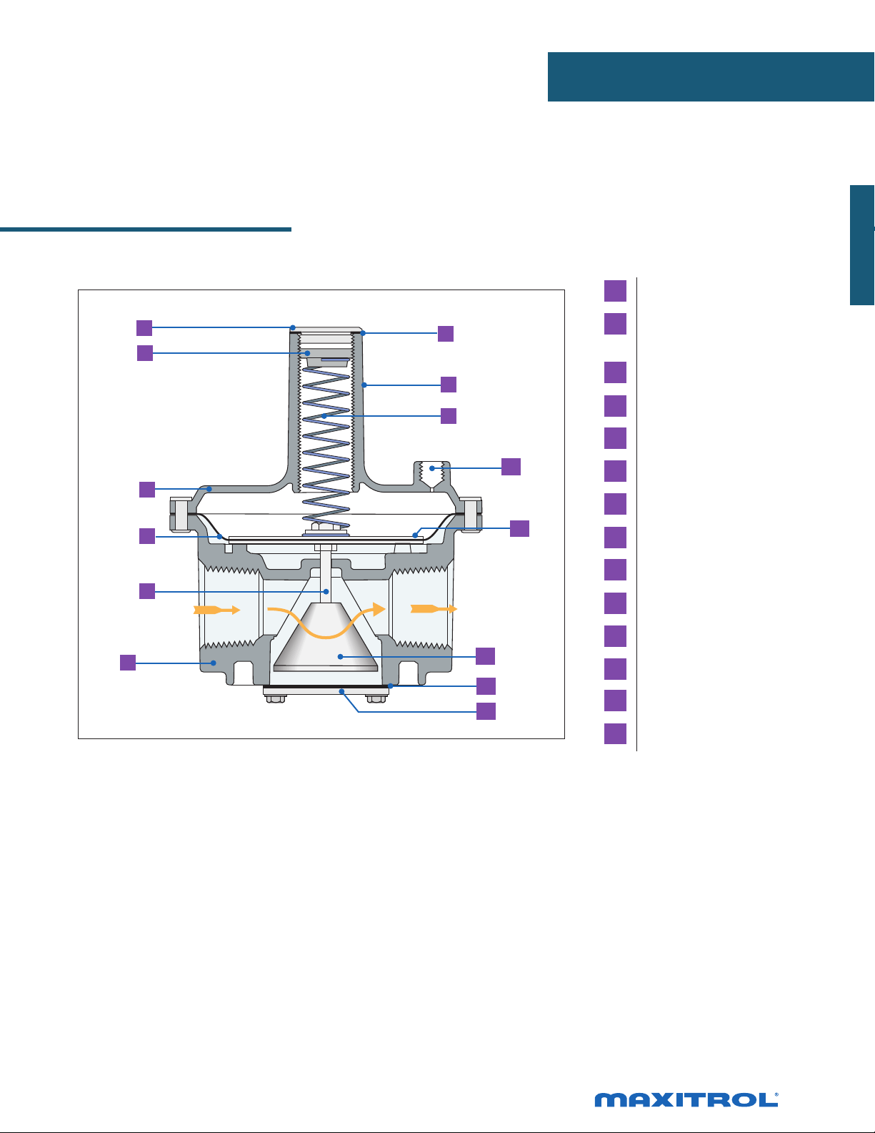
APPLIANCE REGULATORS
A
Lever Acting Design
1
A
325-7A 325-9
1 Seal Cap
2 Stack
6
3 Top Housing
2
7
8
9
3
4
5
NOTE: Diagrams are graphical representations only and may differ from actual product.
10
11
12
4 Rubber Valve
5 Valve Seat
6 Seal Cap Gasket
7 Adjusting Screw
8 Spring
9 Vent Connection
10 Diaphragm
11 Diaphragm Plates
12 Bottom Housing
17
Page 18
R/RS SERIES
Balanced Valve Design
The R & RS series’ double diaphragm balanced valve design
makes it possible to maintain steady outlet pressure control
with widely varying inlet pressures. The regulator is physically
small yet has exceptional capacity characteristics. R & RS series
regulators are intended for use with both main burner and pilot
load applications. They are ideally suited for use with infrared
heaters and pilot lines on large industrial heaters and boilers.
Specications
R400
Pipe Sizes ..................................... 3/8” to 1” threaded connections with NPT or ISO7-1 threads.
Housing Material ......................... R400(S), R500(S), R600(S): aluminum.
Mounting ..................................... Suitable for multi-positional mounting. If ball check vent limiting device is installed, mount
in an upright position only.
NOTE: All Maxitrol gas pressure regulators should be installed and operated in accordance
with Maxitrol Safety Warning Instructions (see GPR_MI_EN.ES or GPR_CSA_MI_EN.FR).
Certications .................................. R400(S), R500(S), R600(S): ANSI Z21.18/CSA 6.3 Gas Appliance Pressure Regulators.
Gas Types ........................................ Suitable for natural, manufactured, mixed gases, liqueed petroleum gases, and LP gas-air
mixtures.
Rated Inlet Pressure ........................ CSA Certied: R400(S), R500(S), R600(S): 1/2 psi (3.4 kPa)
Maxitrol Tested: .............................. R400, R500, R600: 1 psi (6.9 kPa);
R400S, R500S, R600S: 5 psi (34.5 kPa)
Emergency Exposure Limits ............R400, R500, R600: 2 psi (13.8 kPa)
R400S, R500S, R600S: 12.5 psi (86.2)
Ambient Temperature Ranges ........ R400(S), R500(S), R600(S): -40° to 205°F (-40° to 96°C)
Zero Governor Models ...................Please refer to pages 32-37 for RZ model information.
Minimum Regulation .................... Suitable for pilot ow applications. (Circle P) (0.15 CFH NG), None (1.5 CFH NG).
NOTE: These R/RS regulators are not suitable for dead-end lockup service. They are capable of controlling pressure
at very low ows such as standing pilots, but should not be used as a line pressure regulator for appliances
equipped with electronic ignition unless the automatic control valve can open against line pressure.
18
© 2017, Maxitrol Company. All Rights Reserved.
Page 19
Capacities and Pressure Drop
C
US
®
Capacities expressed in CFH (m3/h) @ 0.64 sp gr gas
Model Pipe Size
0.2
(0.05)
0.4
(0.10)
0.6
(0.15)
Pressure Drop - inches w.c. (kPa)
0.8
(0.20)
1.0
(0.25)
1.5
(0.37)
APPLIANCE REGULATORS
UA.TR.012-13
2.0
(0.50)
2.5
(0.62)
3.0
(0.75)
3.5
(0.87)
4.0
(1.0)
R400(S)
R500(S)
R600(S)
3/8” x 3/8”
1/2” x 1/2”
1/2” x 1/2”
3/4” x 3/4”
3/4” x 3/4”
1” x 1”
77
(2.3)
86
(2.4)
163
(4.6)
196
(5.5)
298
(8.3)
330
(9.2)
110
(3.1)
121
(3.4)
231
(6.5)
277
(7.8)
421
(11.8)
468
(13.1)
134
(3.8)
148
(4.1)
283
(7.9)
340
(9.5)
516
(14.5)
572
(16.2)
155
(4.3)
172
(4.82)
327
(9.2)
392
(11.0)
595
(16.7)
661
(18.2)
174
(4.9)
192
(5.4)
366
(10.3)
438
(12.3)
666
(18.7)
739
(20.7)
212
(5.9)
235
(6.6)
447
(12.5)
537
(15.0)
816
(22.9)
906
(25.4)
245
(6.9)
271
(7.6)
516
(14.6)
620
(17.4)
942
(26.4)
1046
(29.3)
274
(7.7)
303
(8.5)
577
(16.2)
693
(19.4)
1054
(29.5)
1169
(32.7)
--- --- ---
--- --- ---
635
(17.9)
760
(21.3)
1150
(32.2)
1280
(35.8)
685
(19.2)
820
(23.0)
1245
(34.86)
1380
(38.64)
730
(20.44)
876
(24.53)
1335
(37.38)
1480
(41.44)
NOTE: CSA maximum capacities vary with spring range and pipe size. Please contact Maxitrol directly for CSA maximums.
See pages 58-59 for Regulator Sizing Requirements and Examples.
Spring Selection Chart: inches w.c. (kPa)
Model CSA Certied Springs Other Springs Available
R400(S)
R500(S)
R600(S)
3 to 6
(0.75 to 1.5)
Plated
3 to 6
(0.75 to 1.5)
Plated
3 to 6
(0.75 to 1.5)
Plated
---
4 to 8
(1 to 2)
Orange
4 to 8
(1 to 2)
Orange
5 to 12
(1.25 to 3)
Blue
5 to 12
(1.25 to 3)
Blue
5 to 12
(1.25 to 3)
Blue
1 to 3.5
(0.25 to 0.9)
Brown
1 to 3.5
(0.25 to 0.9)
Brown
1 to 3.5
(0.25 to 0.9)
Brown
2 to 5
(0.5 to 1.25)
Plated
2 to 5
(0.5 to 1.25)
Plated
2 to 5
(0.5 to 1.25)
Plated
3 to 8
(0.75 to 2)
Pink
3 to 8
(0.75 to 2)
Pink
3 to 8
(0.75 to 2)
Pink
4 to 12
(1 to 3)
Violet
4 to 12
(1 to 3)
Violet
4 to 12
(1 to 3)
Violet
10 to 22
(2.5 to 5.5)
Red
10 to 22
(2.5 to 5.5)
Red
10 to 22
(2.5 to 5.5)
Red
---
---
15 to 30
(3.7 to 7.5)
Yellow
NOTE: See pages 56-57 for complete Spring Selection Chart.
19
Page 20
A
D
R/RS SERIES
Balanced Valve Design
Dimensions
2”
(51 mm)
3.1”
(79 mm)
3.9”
(99 mm)
Dimensions
(51 mm)
(76 mm)
(103 mm)
Model Pipe Size
R400(S) 3/8”, 1/2” 1/8” NPT
R500(S) 1/2”, 3/4” 1/8” NPT
R600(S) 3/4”, 1” 1/8” NPT
Vent
Connection
Swing Radius
2.4”
(60 mm)
3.6”
(90 mm)
4.3”
(110 mm)
A B C D
3.3”
(83 mm)
4.7”
(119 mm)
5.7”
(145 mm)
NOTE: Dimensions are maximums and to be used only as an aid in designing clearance for the valve.
Actual production dimensions may vary somewhat from those shown.
2”
3”
4”
0.9”
(24 mm)
1.2”
(30 mm)
1.5”
(38 mm)
A
D
R500(S), R600(S)
R400(S)
20
© 2017, Maxitrol Company. All Rights Reserved.
Page 21
R/RS Balanced Valve Design
1
2
10
APPLIANCE REGULATORS
1 Welch Plug/Seal Cap
7
8
9
2 Vibration Resistant
Adjusting Screw
3 Top Housing
4 Regulating Diaphragm
5 Stem & Valve
3
4
11
5
6
12
13
NOTE: Diagrams are graphical representations only and may differ from actual product.
6 Bottom Housing
7 Seal Cap Gasket
8 Stack
9 Spring
10 Vent Connection
11 Balancing Diaphragm
12 Bottom Plate Gasket
13 Bottom Plate
21
Page 22

210 SERIES
Balanced Valve Design
The 210 series is a lockup type regulator. The balanced valve
design makes it possible to maintain steady outlet pressure
control with widely varying inlet pressures. The regulator has
an integrated dampening mechanism in the breather outlet
and the sensing tube to improve regulating stability and reduce
hunting tendencies. The 210 series provides precise regulation
over a wide range of pressures and ow rates. Applications
include gas-red boilers, steam generators, industrial furnaces,
and ovens.
Specications
21OE
Pipe Sizes ..................................1” to 3” threaded connections with NPT or ISO7-1 threads. 4” 125 lb. ange (210J only).
Housing Material ...................... 210D, 210E, 210G, 210J: aluminum.
Mounting ................................... Mount in an upright position only.
NOTE: All Maxitrol gas pressure regulators should be installed and operated in accordance
with Maxitrol Safety Warning Instructions (see GPR_MI_EN.ES or GPR_CSA_MI_EN.FR).
Certications ............................. 210D, 210E, 210G: ANSI Z21.18/CSA 6.3 Gas Appliance Pressure Regulators.
Gas Types ................................... Suitable for natural, manufactured, mixed gases, liqueed petroleum gases, and LP gas-air
Maximum Inlet Pressure ............ CSA Certied: 210D, 210E, 210G: 10 psi (69 kPa)
Maxitrol Tested........................... 210J: 10 psi (69 kPa)
Emergency Exposure Limits ....... 210D, 210E, 210G, 210J: 25 psi (172 kPa)
Ambient Temperature Ranges .... -40° to 200°F (-40° to 93°C)
Sensing Taps .............................. Convenient tap locations are available for downstream sensing, cross connections, and
Remote Sensing ......................... 210D, 210E, 210G models may be ordered with remote sensing. The internal sensing tube is
omitted and external sensing taps are provided. Add sufx letter “R” to model number when
ordering.
mixtures.
differential control. Four locations can be tapped and plugged for measuring pressure.
Zero Governor Models .............. Please refer to pages 32-37 for 210Z model information.
Minimum Regulation ................. 210D: 25 CFH; 210E, 210G: 50 CFH; 210J: 100 CFH.
22
© 2017, Maxitrol Company. All Rights Reserved.
Page 23

Capacities
C
US
®
Capacities expressed in CFH (m3/h) @ 0.64 sp gr gas
APPLIANCE REGULATORS
UA.TR.012-13
Model Pipe Size
210D 1” x 1”
Inlet
Pressure
8.0” w.c.
0.5 psi
0.75 psi
1 psi
1.5 psi
2 psi
3 psi
5 psi
7.5 psi
10 psi
2.0
(0.5)
2400
(68.0)
3400
(96.3)
3500
(99.1)
3500
(99.1)
3500
(99.1)
3500
(99.1)
3500
(99.1)
3500
(99.1)
3500
(99.1)
3500
(99.1)
4.0
(1.0)
1900
(53.8)
3100
(87.8)
4000
(113)
4000
(113)
4000
(113)
4000
(113)
4000
(113)
4000
(113)
4000
(113)
4000
(113)
Outlet Pressure - inches w.c. (kPa)
6.0
(1.5)
1300
(36.8)
2700
(76.5)
3800
(108)
4500
(127)
4500
(127)
4500
(127)
4500
(127)
4500
(127)
4500
(127)
4500
(127)
9.0
(2.25)
--- --- --- --- --- ---
2200
(62.3)
3400
(96.3)
4300
(122)
4800
(136)
4800
(136)
4800
(136)
4800
(136)
4800
(136)
4800
(136)
12
(3.0)
--- --- --- --- ---
2900
(82.1)
3900
(110)
4800
(136)
4800
(136)
4800
(136)
4800
(136)
4800
(136)
4800
(136)
16
(4.0)
2200
(62.3)
3400
(96.3)
5000
(142)
5000
(142)
5000
(142)
5000
(142)
5000
(142)
5000
(142)
20
(5.0)
--- --- ---
2700
(76.5)
4600
(130)
5000
(142)
5000
(142)
5000
(142)
5000
(142)
5000
(142)
24
(6.0)
1900
(53.8)
4100
(116)
5000
(142)
5000
(142)
5000
(142)
5000
(142)
5000
(142)
28
(7.0)
---
3600
(102)
5000
(142)
5000
(142)
5000
(142)
5000
(142)
5000
(142)
NOTE: CSA maximum capacities vary with spring range and pipe size. Please contact Maxitrol directly for CSA maximums.
See pages 58-59 for Regulator Sizing Requirements and Examples.
23
Page 24

210 SERIES
Balanced Valve Design
Capacities
Capacities expressed in CFH (m3/h) @ 0.64 sp gr gas
Model Pipe Size
210D
1 1/4”
x
1 1/4”
Inlet
Pressure
8.0” w.c.
0.5 psi
0.75 psi
1 psi
1.5 psi
2 psi
3 psi
5 psi
7.5 psi
10 psi
2.0
(0.5)
3000 (84.9) 2400 (68.0) 1700 (48.1) --- --- --- --- --- ---
4000 (113) 3905 (111) 3400 (96.3) 2700 (76.5) --- --- --- --- ---
4000 (113) 5000 (142) 4700 (133) 4200 (119) 3700 (105) 2700 (76.5) --- --- ---
4000 (113) 5000 (142) 5000 (142) 5300 (150) 4900 (139) 4200 (119) 3400 (96.3) 2400 (68.0) ---
4000 (113) 5000 (142) 5000 (142) 6000 (170) 6000 (170) 6000 (170) 5700 (161) 5200 (147) 4600 (130)
4000 (113) 5000 (142) 5000 (142) 6000 (170) 6000 (170) 6000 (170) 6500 (184) 6500 (184) 6500 (184)
4000 (113) 5000 (142) 5000 (142) 6000 (170) 6000 (170) 6000 (170) 6500 (184) 6500 (184) 6500 (184)
4000 (113) 5000 (142) 5000 (142) 6000 (170) 6000 (170) 6000 (170) 6500 (184) 6500 (184) 6500 (184)
4000 (113) 5000 (142) 5000 (142) 6000 (170) 6000 (170) 6000 (170) 6500 (184) 6500 (184) 6500 (184)
4000 (113) 5000 (142) 5000 (142) 6000 (170) 6000 (170) 6000 (170) 6500 (184) 6500 (184) 6500 (184)
4.0
(1.0)
Capacities expressed in CFH (m3/h) @ 0.64 sp gr gas
Model Pipe Size
Inlet
Pressure
2.0
(0.5)
4.0
(1.0)
6.0
(1.5)
6.0
(1.5)
Outlet Pressure - inches w.c. (kPa)
9.0
(2.25)
Outlet Pressure - inches w.c. (kPa)
9.0
(2.25)
12
(3.0)
12
(3.0)
16
(4.0)
16
(4.0)
20
(5.0)
20
(5.0)
24
(6.0)
24
(6.0)
28
(7.0)
28
(7.0)
3100 (87.8) 2500 (70.8) 1800 (51.0) --- --- --- --- --- ---
0.5 psi
1.5 psi
7.5 psi
4000 (113) 4000 (113) 3600 (102) 2800 (79.3) --- --- --- --- ---
4000 (113) 5000 (142) 5000 (142) 4400 (125) 3800 (108) 2800 (79.3) --- --- ---
4000 (113) 5000 (142) 5000 (142) 5600 (159) 5100 (144) 4400 (125) 3600 (102) 2500 (70.8) ---
1 psi
4000 (113) 5000 (142) 5000 (142) 6000 (170) 6000 (170) 6500 (184) 6000 (170) 5400 (153) 4800 (136)
4000 (113) 5000 (142) 5000 (142) 6000 (170) 6000 (170) 6500 (184) 6500 (184) 6500 (184) 6500 (184)
2 psi
4000 (113) 5000 (142) 5000 (142) 6000 (170) 6000 (170) 6500 (184) 6500 (184) 6500 (184) 6500 (184)
3 psi
4000 (113) 5000 (142) 5000 (142) 6000 (170) 6000 (170) 6500 (184) 6500 (184) 6500 (184) 6500 (184)
5 psi
4000 (113) 5000 (142) 5000 (142) 6000 (170) 6000 (170) 6500 (184) 6500 (184) 6500 (184) 6500 (184)
4000 (113) 5000 (142) 5000 (142) 6000 (170) 6000 (170) 6500 (184) 6500 (184) 6500 (184) 6500 (184)
10 psi
210D
8.0” w.c.
0.75 psi
1 1/2”
x
1 1/2”
NOTE: CSA maximum capacities vary with spring range and pipe size. Please contact Maxitrol directly for CSA maximums.
See pages 58-59 for Regulator Sizing Requirements and Examples.
24
© 2017, Maxitrol Company. All Rights Reserved.
Page 25

Capacities
Capacities expressed in CFH (m3/h) @ 0.64 sp gr gas
APPLIANCE REGULATORS
Model Pipe Size
210E
1 1/2”
x
1 1/2”
Inlet
Pressure
8.0” w.c.
0.5 psi
0.75 psi
1 psi
1.5 psi
2 psi
3 psi
5 psi
7.5 psi
10 psi
2.0
(0.5)
4450 (126) 3650 (103) 2550 (72.2) --- --- --- --- --- ---
6300 (178) 5750 (163) 5150 (146) 4050 (115) --- --- --- --- ---
7000 (198) 7500 (212) 7050 (200) 6300 (178) 5450 (154) 4050 (115) --- --- ---
7000 (198) 8800 (249) 8500 (241) 7950 (225) 7250 (205) 6300 (178) 5150 (146) 3650 (103) ---
7000 (198) 8800 (249) 8800 (249) 10450 (296) 9950 (282) 9250 (262) 8550 (242) 7700 (218) 6800 (193)
7000 (198) 8800 (249) 8800 (249) 10500 (297) 10500 (297) 10500 (297) 10500 (297) 10250 (290) 9600 (272)
7000 (198) 8800 (249) 8800 (249) 10500 (297) 10500 (297) 10500 (297) 10500 (297) 10500 (297) 10500 (297)
7000 (198) 8800 (249) 8800 (249) 10500 (297) 10500 (297) 10500 (297) 10500 (297) 10250 (290) 10500 (297)
7000 (198) 8800 (249) 8800 (249) 10500 (297) 10500 (297) 10500 (297) 10500 (297) 10250 (290) 10500 (297)
7000 (198) 8800 (249) 8800 (249) 10500 (297) 10500 (297) 10500 (297) 10500 (297) 10250 (290) 10500 (297)
4.0
(1.0)
Capacities expressed in CFH (m3/h) @ 0.64 sp gr gas
Model Pipe Size
Inlet
Pressure
2.0
(0.5)
4.0
(1.0)
6.0
(1.5)
6.0
(1.5)
Outlet Pressure - inches w.c. (kPa)
9.0
(2.25)
12
(3.0)
16
(4.0)
Outlet Pressure - inches w.c. (kPa)
9.0
(2.25)
12
(3.0)
16
(4.0)
20
(5.0)
20
(5.0)
24
(6.0)
24
(6.0)
28
(7.0)
28
(7.0)
8.0” w.c.
0.75 psi
210E 2” x 2”
5150 (146) 4200 (119) 2950 (83.5) --- --- --- --- --- ---
7250 (205) 6650 (188) 5950 (168) 4700 (133) --- --- --- --- ---
0.5 psi
8000 (226) 8650 (245) 8150 (231) 7250 (205) 6300 (178) 4700 (133) --- --- ---
8000 (226) 10000 (283) 9850 (279) 9150 (259) 8400 (238) 7250 (205) 5950 (168) 4200 (119) ---
1 psi
8000 (226) 10000 (283) 10000 (283) 12000 (340) 11500 (326) 10700 (303) 9850 (279) 8900 (252) 7850 (222)
1.5 psi
8000 (226) 10000 (283) 10000 (283) 12000 (340) 12000 (340) 12000 (340) 12000 (340) 11850 (335) 11000 (311)
2 psi
8000 (226) 10000 (283) 10000 (283) 12000 (340) 12000 (340) 12000 (340) 12000 (340) 12000 (340) 12000 (340)
3 psi
8000 (226) 10000 (283) 10000 (283) 12000 (340) 12000 (340) 12000 (340) 12000 (340) 12000 (340) 12000 (340)
5 psi
8000 (226) 10000 (283) 10000 (283) 12000 (340) 12000 (340) 12000 (340) 12000 (340) 12000 (340) 12000 (340)
7.5 psi
8000 (226) 10000 (283) 10000 (283) 12000 (340) 12000 (340) 12000 (340) 12000 (340) 12000 (340) 12000 (340)
10 psi
NOTE: CSA maximum capacities vary with spring range and pipe size. Please contact Maxitrol directly for CSA maximums.
See pages 58-59 for Regulator Sizing Requirements and Examples.
25
Page 26

210 SERIES
Balanced Valve Design
Capacities
Capacities expressed in CFH (m3/h) @ 0.64 sp gr gas
Model
210G
Pipe
Size
2 1/2”
x
2 1/2”
Inlet
Pressure
8.0” w.c.
0.5 psi
0.75 psi
1 psi
1.5 psi
2 psi
3 psi
5 psi
7.5 psi
10 psi
2.0
(0.5)
10400 (294) 8500 (241) 6000 (170) --- --- --- --- --- ---
14700 (416) 13410 (380) 12000 (340) 9500 (269) --- --- --- --- ---
16000 (453) 17500 (495) 16400 (464) 14700 (416) 12750 (361) 9500 (269) --- --- ---
16000 (453) 20000 (566) 19900 (563) 18500 (524) 16950 (480) 14700 (416) 12000 (340) 8500 (241) ---
16000 (453) 20000 (566) 20000 (566) 24000 (680) 23250 (658) 21600 (612) 19900 (563) 18000 (510) 15850 (449)
16000 (453) 20000 (566) 20000 (566) 24000 (680) 24000 (680) 24000 (680) 24000 (680) 24000 (680) 22450 (636)
16000 (453) 20000 (566) 20000 (566) 24000 (680) 24000 (680) 24000 (680) 24000 (680) 24000 (680) 24000 (680)
16000 (453) 20000 (566) 20000 (566) 24000 (680) 24000 (680) 24000 (680) 24000 (680) 24000 (680) 24000 (680)
16000 (453) 20000 (566) 20000 (566) 24000 (680) 24000 (680) 24000 (680) 24000 (680) 24000 (680) 24000 (680)
16000 (453) 20000 (566) 20000 (566) 24000 (680) 24000 (680) 24000 (680) 24000 (680) 24000 (680) 24000 (680)
4.0
(1.0)
Capacities expressed in CFH (m3/h) @ 0.64 sp gr gas
Model
Pipe
Size
Inlet
Pressure
2.0
(0.5)
4.0
(1.0)
6.0
(1.5)
6.0
(1.5)
Outlet Pressure - inches w.c. (kPa)
9.0
(2.25)
Outlet Pressure - inches w.c. (kPa)
9.0
(2.25)
12
(3.0)
12
(3.0)
16
(4.0)
16
(4.0)
20
(5.0)
20
(5.0)
24
(6.0)
24
(6.0)
28
(7.0)
28
(7.0)
8.0” w.c.
0.75 psi
210G 3” x 3”
11500 (325) 9400 (266) 6600 (187) --- --- --- --- --- ---
16000 (453) 14800 (416) 13200 (374) 10450 (296) --- --- --- --- ---
0.5 psi
16000 (453) 19300 (546) 18100 (516) 16200 (459) 14000 (396) 10450 (296) --- --- ---
16000 (453) 20000 (566) 20000 (566) 20350 (576) 18700 (529) 16200 (459) 13200 (374) 9350 (265) ---
1 psi
16000 (453) 20000 (566) 20000 (566) 24000 (680) 24000 (680) 23800 (674) 21900 (620) 19800 (561) 17450 (494)
1.5 psi
16000 (453) 20000 (566) 20000 (566) 24000 (680) 24000 (680) 27000 (765) 27000 (765) 26400 (748) 24700 (699)
2 psi
16000 (453) 20000 (566) 20000 (566) 24000 (680) 24000 (680) 27000 (765) 27000 (765) 27000 (765) 27000 (765)
3 psi
16000 (453) 20000 (566) 20000 (566) 24000 (680) 24000 (680) 27000 (765) 27000 (765) 27000 (765) 27000 (765)
5 psi
16000 (453) 20000 (566) 20000 (566) 24000 (680) 24000 (680) 27000 (765) 27000 (765) 27000 (765) 27000 (765)
7.5 psi
16000 (453) 20000 (566) 20000 (566) 24000 (680) 24000 (680) 27000 (765) 27000 (765) 27000 (765) 27000 (765)
10 psi
NOTE: CSA maximum capacities vary with spring range and pipe size. Please contact Maxitrol directly for CSA maximums.
See pages 58-59 for Regulator Sizing Requirements and Examples.
26
© 2017, Maxitrol Company. All Rights Reserved.
Page 27

Capacities
Capacities expressed in CFH (m3/h) @ 0.64 sp gr gas
Model
Pipe
Size
Inlet
Pressure
2.0
(0.5)
4.0
(1.0)
6.0
(1.5)
APPLIANCE REGULATORS
Outlet Pressure - inches w.c. (kPa)
9.0
(2.25)
12
(3.0)
16
(4.0)
20
(5.0)
24
(6.0)
28
(7.0)
210J 4” x 4”
8.0” w.c.
0.5 psi
0.75 psi
1 psi
1.5 psi
2 psi
3 psi
5 psi
7.5 psi
10 psi
20800
(589)
29500
(835)
32000
(906)
32000
(906)
32000
(906)
32000
(906)
32000
(906)
32000
(906)
32000
(906)
32000
(906)
17000
(481)
27000
(764)
35000
(991)
40000
(1132)
40000
(1132)
40000
(1132)
40000
(1132)
40000
(1132)
40000
(1132)
40000
(1132)
12000
(339)
24000
(680)
33000
(934)
40000
(1132)
40000
(1132)
40000
(1132)
40000
(1132)
40000
(1132)
40000
(1132)
40000
(1132)
--- --- --- --- --- ---
19000
(538)
29420
(833)
37000
(1048)
48000
(1359)
48000
(1359)
48000
(1359)
48000
(1359)
48000
(1359)
48000
(1359)
--- --- --- --- ---
25500
(722)
34000
(963)
47000
(1331)
48000
(1359)
48000
(1359)
48000
(1359)
48000
(1359)
48000
(1359)
19000
(538)
29420
(833)
43350
(1227)
50000
(1416)
50000
(1416)
50000
(1416)
50000
(1416)
50000
(1416)
--- --- ---
24000
(680)
39700
(1124)
50000
(1416)
50000
(1416)
50000
(1416)
50000
(1416)
50000
(1416)
17000
(481)
36000
(1019)
48000
(1359)
50000
(1416)
50000
(1416)
50000
(1416)
50000
(1416)
---
31800
(900)
45000
(1274)
50000
(1416)
50000
(1416)
50000
(1416)
50000
(1416)
NOTE: CSA maximum capacities vary with spring range and pipe size. Please contact Maxitrol directly for CSA maximums.
See pages 58-59 for Regulator Sizing Requirements and Examples.
27
Page 28

210 SERIES
Balanced Valve Design
Pressure Drop: inches w.c. (kPa)
Flow Rate
CFH (m3/h)
500 (14.2) 0.23 (0.06) 0.15 (0.04) 0.14 (0.03) --- --- --- --- --1000 (28.3) 0.92 (0.23) 0.59 (0.15) 0.54 (0.13) 0.27 (0.07) 0.20 (0.05) 0.05 (0.01) 0.04 (0.009) 0.01 (0.002)
1500 (42.5) 2.08 (0.52) 1.33 (0.33) 1.22 (0.30) --- --- --- --- --2000 (56.6) 3.07 (0.76) 2.37 (0.59) 2.16 (0.54) 1.09 (0.27) 0.82 (0.20) 0.20 (0.05) 0.17 (0.04) 0.05 (0.01)
2500 (70.8) 5.78 (1.44) 3.70 (0.92) 3.38 (0.84) --- --- --- --- --3000 (85.0) 8.32 (2.07) 5.33 (1.33) 4.87 (1.21) 2.46 (0.61) 1.84 (0.46) 0.45 (0.11) 0.37 (0.09) 0.12 (0.03)
3500 (99.1) 11.33 (2.82) 7.25 (1.81) 6.62 (1.65) --- --- --- --- --4000 (113) 14.79 (3.68) 9.47 (2.36) 8.65 (2.15) 4.37 (1.09) 3.28 (0.82) 0.80 (0.20) 0.66 (0.16) 0.21 (0.05)
4500 (127) 18.72 (4.66) 11.98 (2.98) 10.95 (2.73) --- --- --- --- --5000 (142) 23.11 (5.76) 14.79 (3.68) 13.52 (3.37) 6.82 (1.70) 5.12 (1.28) 1.25 (0.31) 1.03 (0.26) 0.34 (0.08)
5500 (156) 27.97 (6.97) 17.90 (4.46) 16.35 (4.07) --- --- --- --- --6000 (170) 33.28 (8.29) 21.30 (5.30) 19.46 (4.85) 9.82 (2.45) 7.37 (1.84) 1.80 (0.45) 1.48 (0.37) 0.49 (0.12)
6500 (184) --- 25.00 (6.23) 22.84 (5.69) --- --- --- --- --7000 (198) --- 28.99 (7.22) 26.49 (6.60) 13.36 (3.33) 10.05 (2.50) 2.45 (0.61) 2.02 (0.50) 0.66 (0.16)
7500 (212) --- --- 30.41 (7.57) --- --- --- --- --8000 (226) --- --- --- 17.45 (4.35) 13.10 (3.26) 3.20 (0.80) 2.64 (0.66) 0.87 (0.22)
8500 (241) --- --- --- --- --- --- --- --9000 (255) --- --- --- 22.10 (5.50) 16.60 (4.13) 4.05 (1.01) 3.35 (0.83) 1.10 (0.27)
9500 (269) --- --- --- --- --- --- --- ---
10000 (283) --- --- --- 27.30 (6.80) 20.50 (5.11) 5.00 (1.24) 4.15 (1.03) 1.35 (0.34)
11000 (311) --- --- --- 33.00 (8.22) 24.80 (6.18) 6.05 (1.51) 5.00 (1.24) --12000 (340) --- --- --- 39.30 (9.79) 29.50 (7.35) 7.20 (1.79) 5.95 (1.48) 1.95 (0.48)
13000 (368) --- --- --- --- 34.60 (8.62) 8.50 (2.12) 7.00 (1.74) --14000 (369) --- --- --- --- 40.15 (10.00) 9.85 (2.45) 8.10 (2.01) 2.68 (0.67)
15000 (425) --- --- --- --- --- 11.30 (2.81) 9.30 (2.32) --16000 (453) --- --- --- --- --- 12.85 (3.20) 10.60 (2.64) 3.47 (0.86)
17000 (481) --- --- --- --- --- 14.50 (3.61) 11.95 (2.98) --18000 (510) --- --- --- --- --- 16.25 (4.05) 13.40 (3.34) 4.40 (1.09)
19000 (538) --- --- --- --- --- 18.10 (4.51) 14.90 (3.71) --20000 (566) --- --- --- --- --- 20.05 (4.99) 16.50 (4.11) 5.42 (1.35)
22000 (623) --- --- --- --- --- 24.25 (6.40) 20.00 (4.98) 6.56 (1.63)
24000 (680) --- --- --- --- --- 28.85 (7.19) 23.80 (5.93) 7.81 (1.94)
26000 (736) --- --- --- --- --- 33.85 (8.43) 27.90 (6.95) 9.06 (2.26)
28000 (793) --- --- --- --- --- 39.25 (9.78) 32.40 (8.07) 10.62 (2.64)
30000 (849) --- --- --- --- --- --- 37.20 (9.27) 12.41 (3.09)
32000 (906) --- --- --- --- --- --- --- 13.90 (3.46)
34000 (963) --- --- --- --- --- --- --- 15.69 (3.91)
36000 (1019) --- --- --- --- --- --- --- 17.60 (4.38)
38000 (1076) --- --- --- --- --- --- --- 19.60 (4.88)
40000 (1133) --- --- --- --- --- --- --- 21.70 (5.40)
45000 (1274) --- --- --- --- --- --- --- 27.40 (6.82)
50000 (1416) --- --- --- --- --- --- --- 33.80 (8.42)
55000 (1557) --- --- --- --- --- --- --- 41.00 (10.21)
1” 1 1/4” 1 1/2” 1 1/2” 2” 2 1/2” 3” 4”
210D 210E 210G 210J
NOTE: The maximum capacities for the different models listed on the capacity charts and represented by the heavy line on the
pressure drop are values at which these controls have been certied by CSA (except for the 210J). See pages 58-59 for
Regulator Sizing Requirements and Examples.
28
© 2017, Maxitrol Company. All Rights Reserved.
Page 29

Spring Selection Chart: inches w.c. (kPa)
APPLIANCE REGULATORS
Model CSA Certied Springs
210D
210E
210G
210J
1 to 3.5
(0.25 to 0.9)
Brown
1 to 3.5
(0.25 to 0.9)
Brown
1 to 3.5
(0.25 to 0.9)
Brown
---
2 to 5
(0.5 to 1.25)
Plated
2 to 5
(0.5 to 1.25)
Plated
2 to 5
(0.5 to 1.25)
Plated
2 to 5
(0.5 to 1.25)
Plated
3 to 6
(0.75 to 1.5)
Plated
3 to 6
(0.75 to 1.5)
Plated
3 to 6
(0.75 to 1.5)
Plated
3 to 6
(0.75 to 1.5)
Plated
3 to 8
(0.75 to 2)
Pink
3 to 8
(0.75 to 2)
Pink
3 to 8
(0.75 to 2)
Pink
3 to 8
(0.75 to 2)
Pink
4 to 8
(1 to 2)
Orange
4 to 8
(1 to 2)
Orange
4 to 8
(1 to 2)
Orange
---
4 to 12
(1 to 3)
Violet
4 to 12
(1 to 3)
Violet
4 to 12
(1 to 3)
Violet
4 to 12
(1 to 3)
Violet
5 to 12
(1.25 to 3)
Blue
5 to 12
(1.25 to 3)
Blue
5 to 12
(1.25 to 3)
Blue
5 to 12
(1.25 to 3)
Blue
5 to 15
(1.25 to 3.7)
Green
5 to 15
(1.25 to 3.7)
Green
5 to 15
(1.25 to 3.7)
Green
---
10 to 22
(2.5 to 5.5)
Red
10 to 22
(2.5 to 5.5)
Red
10 to 22
(2.5 to 5.5)
Red
10 to 22
(2.5 to 5.5)
Red
15 to 30
(3.7 to 7.5)
Yellow
15 to 30
(3.7 to 7.5)
Yellow
15 to 30
(3.7 to 7.5)
Yellow
15 to 30
(3.7 to 7.5)
Yellow
Other
Springs
20 to 42
(5 to 10.5)
Black
20 to 42
(5 to 10.5)
Black
20 to 42
(5 to 10.5)
Black
20 to 42
(5 to 10.5)
Black
NOTE: The area within the heavy line indicates CSA certied springs. See pages 56-57 for complete Spring Selection Chart.
29
Page 30

210 SERIES
Balanced Valve Design
Dimensions
7”
(178 mm)
9.1”
(232 mm)
13.5”
(343 mm)
18”
(457 mm)
Dimensions
(152 mm)
(203 mm)
11.8”
(300 mm)
13.8”
(349 mm)
Model Pipe Size
210D 1”, 1 1/4”, 1 1/2” 3/8” NPT
210E 1 1/2”, 2” 1/2” NPT
210G 2 1/2”, 3” 3/4” NPT
210J 4” 3/4” NPT
Vent
Connection
Swing Radius
5.4”
(138 mm)
8.3”
(211 mm)
11.9”
(302 mm)
18.4”
(467 mm)
A B C D
9”
(228 mm)
11.3”
(286 mm)
16.5”
(419 mm)
24.3”
(616 mm)
NOTE: Dimensions are maximums and to be used only as an aid in designing clearance for the valve.
Actual production dimensions may vary somewhat from those shown.
6”
8”
2.4”
(60 mm)
2.9”
(75 mm)
4.6”
(116 mm)
5.4”
(138 mm)
30
A
A
D
D
210J210D, 210E, 210G
© 2017, Maxitrol Company. All Rights Reserved.
Page 31
210 Balanced Valve Design
1
2
10
APPLIANCE REGULATORS
1 Welch Plug/Seal Cap
7
8
9
2 Vibration Resistant
Adjusting Screw
3 Top Housing
4 Regulating Diaphragm
5 Stem & Valve
3
4
5
6
NOTE: Diagrams are graphical representations only and may differ from actual product.
11
12
13
14
15
6 Bottom Housing
7 Seal Cap Gasket
8 Stack
9 Spring
10 Vent Connection
11 Diaphragm Plates
12 Balancing Diaphragm
13 Sensing Tube
14 Bottom Plate Gasket
15 Bottom Plate
31
Page 32

RZ and 210Z
Zero Governor Design
Both the RZ and 210Z series are adaptable for air-gas mixing
applications. Because of the balanced valve construction,
Z-models offer superior performance at an economical price
compared with other types of atmospheric regulators.
Maxitrol’s RZ and 210Z Zero Governor model regulators are
used for ow control of burners, nozzel mixers, mixing tees and
proportional premixers.
210EZ
Specications
Pipe Sizes .................................. RZ Models: 3/8” to 1” threaded connections with NPT or ISO7-1 threads.
210Z Models: 1” to 3” threaded connections with NPT or ISO7-1 threads.
4” 125 lb. ange (210JZ only).
Housing Material ......................R400Z, R500Z, R600Z, 210DZ, 210EZ, 210GZ, 210JZ: aluminum.
Mounting ..................................R400Z, 210DZ, 210EZ, 210GZ, 210JZ mount in an upright position only. R500Z, R600Z
suitable for multi-positional mounting. If ball check vent limiting device is installed, mount in
an upright position only.
NOTE: All Maxitrol gas pressure regulators should be installed and operated in accordance
with Maxitrol Safety Warning Instructions (see GPR_MI_EN.ES or GPR_CSA_MI_EN.FR).
Certications ..............................R400Z, R500Z, 210DZ, 210EZ, 210GZ: ANSI Z21.18/CSA 6.3 Gas Appl iance Press ure Regulat ors.
Gas Types .................................... Suitable for natural, manufactured, mixed gases, liqueed petroleum gases, and LP gas-air
mixtures.
Rated Inlet Pressure ....................CSA Certied: R400Z, R500Z: 1/2 psi (3.4 kPa); 210DZ, 210EZ, 210GZ: 5 psi (34.5 kPa)
Maxitrol Tested............................R400Z, R500Z, R600Z: 1 psi (6.9 kPa); 210JZ: 5 psi (34.5 kPa)
Emergency Exposure Limits ........R400Z, R500Z, R600Z: 2 psi (13.8 kPa)
210DZ, 210EZ, 210GZ, 210JZ: 25 psi (172 kPa)
Ambient Temperature Ranges ..... R400Z, R600Z: -40° to 205°F (-40° to 96°C)
R500Z: 32° to 205°F (0° to 96°C)
210DZ, 210EZ, 210GZ, 210JZ: -40° to 200°F (-40° to 93°C)
Sensing Taps ..................................210Z Models have convenient tap locations available for downstream sensing, cross connections,
and differential control. Four locations can be tapped and plugged for measuring pressure.
Remote Sensing ......................... 210DZ, 210EZ, 210GZ models may be ordered with remote sensing. The internal sensing
tube is omitted and external sensing taps are provided. Add sufx letter “R” to model number
when ordering.
Minimum Regulation .................R400Z: Suitable for pilot ow applications. (Circle P) (0.15 CFH NG), R500Z, R600Z: 10
CFH.
32
© 2017, Maxitrol Company. All Rights Reserved.
Page 33

Capacities and Pressure Drop
C
US
®
Capacities expressed in CFH (m3/h) @ 0.64 sp gr gas
APPLIANCE REGULATORS
UA.TR.012-13
Pressure Drop - inches w.c. (kPa)
Model Number Pipe Size
3/8” x 3/8”
R400Z
1/2” x 1/2”
1/2” x 1/2”
R500Z
3/4” x 3/4”
3/4” x 3/4”
R600Z
1” x 1”
0.2
(0.05)
77
(2.16)
86
(2.41)
163
(4.56)
196
(5.49)
298
(8.34)
330
(9.24)
0.4
(0.10)
110
(3.08)
121
(3.39)
231
(6.47)
277
(7.76)
421
(11.8)
468
(13.1)
0.6
(0.15)
134
(3.75)
148
(4.14)
283
(7.92)
340
(9.52)
516
(14.5)
572
(16.0)
0.8
(0.20)
155
(4.34)
172
(4.82)
327
(9.16)
392
(11.0)
595
(16.7)
661
(18.2)
1.0
(0.25)
174
(4.87)
192
(5.38)
366
(10.3)
438
(12.3)
666
(18.7)
739
(20.7)
1.5
(0.37)
212
(5.94)
235
(6.58)
447
(12.5)
537
(15.0)
816
(22.9)
906
(25.4)
2.0
(0.50)
245
(6.86)
271
(7.59)
516
(14.6)
620
(17.4)
942
(26.4)
1046
(29.3)
2.5
(0.62)
274
(7.67)
303
(8.48)
577
(16.2)
693
(19.4)
1054
(29.5)
1169
(32.7)
3.0
(0.75)
-- -- --
-- -- --
635
(17.8)
760
(21.3)
1150
(32.2)
1280
(35.8)
3.5
(0.87)
685
(19.2)
820
(22.7)
1245
(34.9)
1380
(38.6)
4.0
(1.0)
730
(20.4)
876
(24.5)
1335
(37.4)
1480
(41.4)
NOTE: CSA maximum capacities vary with spring range and pipe size. Please contact Maxitrol directly for CSA maximums.
See pages 58-59 for Regulator Sizing Requirements and Examples.
33
Page 34

RZ and 210Z
Zero Governor Design
Capacities and Pressure Drop
Capacities expressed in CFH (m3/h) @ 0.64 sp gr gas
Model
Number
210DZ
210EZ
210GZ
Pipe Size
1” x 1” -- -- --
1 1/4”
x
1 1/4”
1 1/2”
x
1 1/2”
1 1/2”
x
1 1/2”
2” x 2” --
2 1/2”
x
2 1/2”
3” x 3”
0.1
(0.025)
-- -- --
-- -- --
--
1410
(39.5)
1555
(43.5)
0.3
(0.075)
1050
(29.4)
1210
(33.9)
2450
(68.6)
2695
(75.5)
0.5
(0.125)
1350
(37.8)
1560
(43.7)
3160
(88.5)
3475
(97.3)
Pressure Drop - inches w.c. (kPa) unless noted
1.0
(0.25)
900
(25.2)
1100
(30.8)
1200
(33.6)
1915
(53.6)
2210
(61.9)
4470
(125)
4920
(138)
3.0
(0.75)
1600
(44.8)
1900
(53.2)
2100
(58.8)
3315
(92.8)
3825
(107)
7740
(217)
8520
(239)
5.0
(1.25)
2000
(56.0)
2500
(70.0)
2700
(75.6)
4280
(120)
4940
(139)
9995
(280)
11000
(308)
7.0
(1.74)
2400
(67.2)
2900
(81.2)
3200
(89.6)
5065
(142)
5845
(164)
11825
(331)
13020
(365)
0.5 psi
(3.45)
3300
(92.4)
4100
(115)
4500
(126)
7125
(199)
8225
(230)
16635
(466)
18310
(513)
0.75 psi
(5.17)
4100
(115)
5000
(140)
5500
(154)
8725
(244)
10070
(282)
20370
(570)
22425
(628)
1 psi
(6.89)
4750
(133)
5850
(164)
6350
(176)
10075
(282)
11630
(326)
23525
(659)
25890
(725)
1.5 psi
(10.34)
5800
(162)
7150
(200)
7750
(217)
12340
(345)
14245
(399)
28810
(807)
31710
(888)
210JZ 4” x 4”
2700
(75.6)
4700
(132)
6000
(168)
8600
(241)
15000
(420)
19000
(532)
23000
(644)
32000
(896)
40000
(1120)
45500
(1274)
55700
(1560)
NOTE: CSA maximum capacities vary with spring range and pipe size. Please contact Maxitrol directly for CSA maximums.
See pages 58-59 for Regulator Sizing Requirements and Examples.
34
© 2017, Maxitrol Company. All Rights Reserved.
Page 35

Spring Selection: inches w.c (kPa)
Model Outlet Pressure Range
APPLIANCE REGULATORS
R400Z
R500Z
R600Z
Model Outlet Pressure Range
210DZ
210EZ
210GZ
-1.5 to 1.0
(-0.37 to 0.25)
-1.0 to 2.5
(-0.25 to 0.62)
-1.0 to 1.5
(-0.25 to 0.37)
-1.0 to 1.5
(-0.25 to 0.37)
-1.0 to 1.5
(-0.25 to 0.37)
-1.0 to 1.5
(-0.25 to 0.37)
210JZ
NOTE: See pages 56-57 for complete Spring Selection Chart.
-1.0 to 1.5
(-0.25 to 0.37)
35
Page 36

RZ and 210Z
Zero Governor Design
Dimensions
2”
(51 mm)
3.1”
(79 mm)
3.9”
(98 mm)
7”
(178 mm)
9.1”
(232 mm)
13.5”
(343 mm)
18”
(457 mm)
Dimensions
2”
(51 mm)
3”
(79 mm)
4”
(102 mm)
6”
(152 mm)
8”
(203 mm)
11.8”
(300 mm)
13.8”
(349 mm)
Model Pipe Size
R400Z 3/8”, 1/2” 1/8” NPT
R500Z 1/2”, 3/4” 1/8” NPT
R600Z 3/4”, 1” 1/8” NPT
210DZ 1”, 1 1/4”, 1 1/2” 3/8” NPT
210EZ 1 1/2”, 2” 1/2” NPT
210GZ 2 1/2”, 3” 3/4” NPT
210JZ 4” 3/4” NPT
Vent
Connection
Swing Radius
2.4”
(60 mm)
3.6”
(90 mm)
4.3”
(109 mm)
5.4”
(138 mm)
8.3”
(211 mm)
11.9”
(302 mm)
18.4”
(467 mm)
A B C D
3.3”
(83 mm)
4.7”
(119 mm)
5.7”
(144 mm)
9”
(229 mm)
11.3”
(286 mm)
16.5”
(419 mm)
24.3”
(616 mm)
NOTE: Dimensions are maximums and to be used only as an aid in designing clearance for the valve.
Actual production dimensions may vary somewhat from those shown.
0.9”
(24 mm)
1.2”
(30 mm)
1.5”
(37 mm)
2.4”
(60 mm)
2.9”
(75 mm)
4.6”
(116 mm)
5.4”
(138 mm)
A
D
R400Z, R500Z, R600Z
36
A
D
210DZ, 210EZ, 210GZ
A
D
210JZ
© 2017, Maxitrol Company. All Rights Reserved.
Page 37

Zero Governor Design
R400Z, R500Z, R600Z
1
2
APPLIANCE REGULATORS
1 Seal Cap
7
8
9
10
2 Adjusting Screw
3 Top Housing
4 Regulating Diaphragm
5 Stem & Valve
3
4
5
6
210DZ, 210EZ, 210GZ, 210JZ
1
2
3
4
5
6
6 Bottom Housing
7 Seal Cap Gasket
11
8 Stack
9 Spring
10 Vent Connection
12
13
11 Balancing Diaphragm
12 Counter Spring
13 Bottom Plate
1 Seal Cap
2 Adjusting Screw
7
8
9
10
3 Top Housing
4 Regulating Diaphragm
5 Stem & Valve
6 Bottom Housing
7 Seal Cap Gasket
11
12
8 Stack
9 Spring
13
10 Vent Connection
11 Diaphragm Plates
12 Balancing Diaphragm
14
15
13 Sensing Tube
14 Counter Spring
15 Bottom Plate
NOTE: Diagrams are graphical representations only and may differ from actual product.
37
Page 38

220 SERIES
Pilot Loaded Design
The 220 series uses a servo-operated design rather than a
spring-loaded design and can deliver higher outlet pressures
than conventional spring-loaded models.
The main diaphragm of the model 220 is loaded with gas pressure
instead of spring pressure. A small pilot regulator, located in the
upper housing, accurately controls this gas pressure. When the
regulated outlet pressure of the servo regulator is changed by
spring adjustment, the outlet pressure of the 220 main regulator
will be changed proportionately. Applications include industrial
furnaces and ovens.
220 D
Specications
Pipe Sizes ................................... 1” to 3” threaded connections with NPT or ISO7-1 threads. 4” 125 lb. ange (220J only).
Housing Material ....................... 220D, 220E, 220G, 220J: aluminum.
Mounting ................................... Mount in an upright position only.
NOTE: All Maxitrol gas pressure regulators should be installed and operated in accordance
with Maxitrol Safety Warning Instructions (see GPR_MI_EN.ES).
Gas Types ................................... Suitable for natural, manufactured, mixed gases, liqueed petroleum gases, and LP gas-air
mixtures.
Maximum Inlet Pressure ............ 10 psi (68.9 kPa)
Flow Rates .................................. up to 50,000 CFH (1416 m3/h)
Emergency Exposure Limits ........ 25 psi (170 kPa)
Ambient Temperature Ranges ..... -40 to 200°F (-40 to 93°C)
Sensing Taps ............................... Three positions can be tapped and plugged for measuring pressure. The fourth position is
used to supply inlet pressure to the pilot regulator.
Remote Sensing .......................... 220D, 220E, 220G models may be ordered with remote sensing. The internal sensing tube is
omitted and external sensing taps are provided. Add sufx letter “R” to model number when
ordering.
NOTE: 220D, 220E, 220G, 220J are not CSA certied.
NOTE: ”L” models available for outlet pressures under 1 psi (6.9 kPa).
38
© 2017, Maxitrol Company. All Rights Reserved.
Page 39

Pressure Drop: inches w.c. (kPa) @ 0.64 sp gr gas
APPLIANCE REGULATORS
Flow Rate
CFH (m3/h)
1000 (28.3) 1.90 (0.47) 1.70 (0.42) 1.70 (0.42) --- --- --- --- ---
2000 (56.6) 4.93 (1.23) 3.10 (0.77) 2.90 (0.72) 1.90 (0.47) 1.90 (0.47) --- --- ---
3000 (85.0) 11.10 (2.76) 7.42 (1.85) 5.40 (1.34) 2.90 (0.72) 2.40 (0.60) --- --- ---
4000 (113) 19.70 (4.91) 13.20 (3.29) 11.10 (2.76) 4.93 (1.23) 4.00 (1.00) 2.00 (0.50) 1.90 (0.47) 1.70 (0.42)
5000 (142) 30.80 (7.67) 20.70 (5.16) 17.40 (4.33) 7.70 (1.92) 6.25 (1.56) 2.20 (0.55) 2.10 (0.52) 1.70 (0.42)
6000 (170) 44.20 (11.01) 29.70 (7.40) 25.00 (6.23) 11.10 (2.76) 9.00 (2.24) 2.60 (0.65) 2.30 (0.57) 1.70 (0.42)
7000 (198) --- 40.60 (10.11) 34.00 (8.47) 15.10 (3.76) 12.25 (3.05) 3.00 (0.75) 2.60 (0.65) 1.70 (0.42)
8000 (226) --- --- 44.50 (11.08) 19.70 (4.91) 16.00 (3.98) 4.00 (1.00) 3.00 (0.75) 1.80 (0.45)
9000 (255) --- --- --- 24.90 (6.20) 20.25 (5.04) 5.00 (1.25) 3.80 (0.95) 1.90 (0.47)
10000 (283) --- --- --- 30.80 (7.67) 25.00 (6.23) 6.22 (1.55) 4.60 (1.15) 2.10 (0.52)
12000 (340) --- --- --- 44.20 (11.01) 36.00 (8.97) 9.00 (2.24) 6.80 (1.69) 2.40 (0.60)
14000 (369) --- --- --- --- --- 12.20 (3.04) 9.30 (2.32) 2.80 (0.70)
16000 (453) --- --- --- --- --- 16.00 (4.00) 12.10 (3.01) 3.40 (0.85)
18000 (510) --- --- --- --- --- 20.20 (5.03) 15.30 (3.81) 4.40 (1.10)
20000 (566) --- --- --- --- --- 25.00 (6.23) 18.90 (4.71) 5.40 (1.35)
25000 (708) --- --- --- --- --- 40.60 (10.11) 30.70 (7.65) 8.90 (2.22)
30000 (849) --- --- --- --- --- --- 42.50 (10.59) 12.40 (3.09)
35000 (991) --- --- --- --- --- --- --- 17.05 (4.25)
40000 (1133) --- --- --- --- --- --- --- 21.70 (5.41)
45000 (1274) --- --- --- --- --- --- --- 27.40 (6.83)
50000 (1416) --- --- --- --- --- --- --- 33.80 (8.42)
55000 (1557) --- --- --- --- --- --- --- 41.00 (10.21)
1” 1 1/4” 1 1/2” 1 1/2” 2” 2 1/2” 3” 4”
220D 220E 220G 220J
NOTE: Do not exceed 36” pressure drop when determining acceptable capacities at which these controls may be used. Under some
conditions, these limits may be surpassed, but only after consultation with Maxitrol. See pages 58-59 for Regulator Sizing
Requirements and Examples.
Spring Selection
Model Available Springs
220D
220E
220G
220J
NOTE: See pages 56-57 for complete Spring Selection Chart.
1 psi to 3 psi
(6.9 kPa to 20.7 kPa)
1 psi to 3 psi
(6.9 kPa to 20.7 kPa)
1 psi to 3 psi
(6.9 kPa to 20.7 kPa)
1 psi to 3 psi
(6.9 kPa to 20.7 kPa)
Red
Red
Red
Red
2 psi to 5 psi
(13.8 kPa to 34.5 kPa)
Yellow
2 psi to 5 psi
(13.8 kPa to 34.5 kPa)
Yellow
2 psi to 5 psi
(13.8 kPa to 34.5 kPa)
Yellow
2 psi to 5 psi
(13.8 kPa to 34.5 kPa)
Yellow
39
Page 40

220 SERIES
Pilot Loaded Design
Dimensions
Model Pipe Size Vent Connection
220D 1”, 1 1/4”, 1 1/2” 12A06 vent limiting device installed.
220E 1 1/2”, 2” 12A06 vent limiting device installed.
220G 2 1/2”, 3” 12A06 vent limiting device installed.
220J 4” 12A06 vent limiting device installed. —
(206 mm)
(217 mm)
(264 mm)
Swing
Radius
8.1”
8.6”
10.4”
A B C D
9.5”
(241 mm)
11.2”
(285 mm)
14.2”
(362 mm)
20.5”
(520 mm)
Dimensions
7”
(178 mm)
9.1”
(232 mm)
13.5”
(343 mm)
18”
(457 mm)
NOTE: Dimensions are maximums and to be used only as an aid in designing clearance for the valve.
Actual production dimensions may vary somewhat from those shown.
5.5”
(140 mm)
7.6”
(194 mm)
10.4”
(264 mm)
13.9”
(352 mm)
8.3”
(210 mm)
10”
(256 mm)
15.8”
(400 mm)
20”
(508 mm)
40
A
A
B
220D, 220E, 220G 220J
© 2017, Maxitrol Company. All Rights Reserved.
Page 41
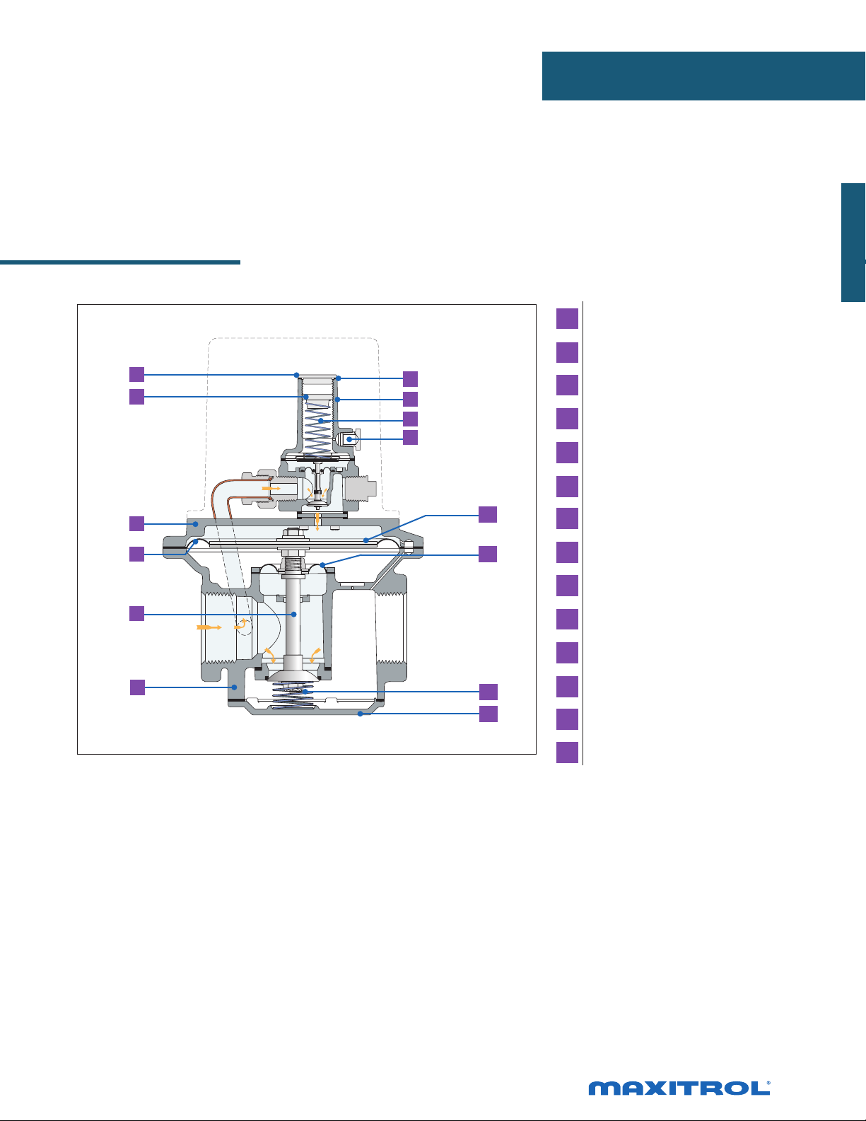
Pilot Loaded Design
1
2
10
APPLIANCE REGULATORS
1 Seal Cap
2 Adjusting Screw
7
8
9
3 Top Housing
4 Regulating Diaphragm
5 Stem & Valve
6 Bottom Housing
3
4
5
6
NOTE: Diagrams are graphical representations only and may differ from actual product.
11
12
13
14
7 Seal Cap Gasket
8 Stack
9 Spring
10 Vent Connection
11 Diaphragm Plates
12 Balancing Diaphragm
13 Counter Spring
14 Bottom Plate
41
Page 42

SR SERIES
2 Stage Design
An ideal replacement for dual manifold systems, the SR Series
combines gas pressure regulating and ame staging in a single
unit. Applications include direct-red heaters with two speed
fans, hi-lo control for outdoor heaters, LP natural gas switchover
and industrial processing.
Specications
SR400
Pipe Sizes ..................................... 3/8” thru 1” threaded connections with NPT or ISO7-1 threads.
Housing Material ......................... SR400, SR500, SR600: aluminum.
Mounting ..................................... Mount in an upright position only.
NOTE: All Maxitrol gas pressure regulators should be installed and operated in accordance
with Maxitrol Safety Warning Instructions (see SELMMRSR_MI_EN.FR.ES).
Certications ............................... SR400, SR500, SR600: ANSI Z21.18/CSA 6.3 Gas Appliance Pressure Regulators
(except sufx -2 models).
Gas Types ..................................... Suitable for natural, manufactured, mixed gases, liqueed petroleum gases, and LP gas-air
mixtures.
Rated Inlet Pressure ..................... CSA Certied: 1/2 psi (3.4 kPa)
Maxitrol Tested ............................. 1 psi (6.9 kPa)
Flow Rates .................................... up to 1,000 CFH (28.32 m3/h)
Emergency Exposure Limits .......... 2.5 psi (17.2 kPa)
Ambient Temperature Ranges ....... -40 to 175°F (-40 to 79°C)
Minimum Regulation .................... SR400, SR500: 5 CFH; SR600: 60 CFH
NOTE: SR400-2, SR500-2, SR600-2 models are designed primarily for LP gas applications.
NOTE: All models may be powered by a 24 volt AC transformer. When the coil is energized, the appliance is at low re.
When the coil is de-energized, it is high re. Continuous regulation is maintained to hold the electrically set outlet
pressure constant.
42
© 2015, Maxitrol Company. All Rights Reserved.
Page 43

Capacities and Pressure Drop: inches w.c. (kPa)
C
US
®
APPLIANCE REGULATORS
Model
Number
SR400
SR500
SR600
Pipe Size
3/8” x 3/8”
1/2” x 1/2”
1/2” x 1/2”
3/4” x 3/4”
3/4” x 3/4”
1” x 1”
CSA
MAX
150
(4.2)
170
(4.8)
360
(10.2)
400
(11.2)
600
(16.8)
600
(16.8)
100
(2.83)
0.33
(0.08)
0.27
(0.07)
0.08
(0.02)
0.05
(0.01)
---
---
200
(5.66)
1.30
(0.32)
1.10
(0.27)
0.30
(0.08)
0.21
(0.05)
0.09
(0.02)
0.07
(0.02)
300
(8.50)
--- --- --- --- --- ---
--- --- --- --- --- ---
0.68
(0.17)
0.47
(0.12)
0.20
(0.05)
0.16
(0.04)
400
(11.33)
1.20
(0.30)
0.83
(0.20)
0.36
(0.09)
0.29
(0.07)
500
(14.16)
--- --- --- ---
1.30
(0.32)
0.56
(0.14)
0.45
(0.11)
600
(16.99)
--- --- ---
0.81
(0.20)
0.66
(0.16)
750
(21.24)
1.25
(0.31)
1.00
(0.25)
1000
(28.32)
---
1.75
(0.44)
NOTE: Capacities expressed in CFH (m3/h) @ 0.64 sp gr gas
CSA maximum capacities vary with spring range and pipe size. Please contact Maxitrol directly for CSA maximums.
See pages 58-59 for Regulator Sizing Requirements and Examples.
Spring Selection: inches w.c. (kPa)
Model Available Springs
Flow Rate - CFH (m3/h)
SR400
SR400-2*
SR500
SR500-2*
SR600
Maximum
Minimum
Maximum 7.5 to 12 (1.87 to 3) - Blue
Maximum
Minimum
Maximum 7.5 to 12 (1.87 to 3) - Black
Maximum
Minimum
3 to 5
(0.75 to 1.25)
S. Steel
0.3 to 1.2
(0.07 to 0.3)
Plated
3 to 5
(0.75 to 1.25)
S. Steel
0.3 to 1.2
(0.07 to 0.3)
Plated
3 to 5
(0.75 to 1.25)
S. Steel
0.5 to 1.2
(0.12 to 0.3)
Plated
2.5 to 3.5
(0.62 to 0.87)
White
0.3 to 1.2
(0.07 to 0.3)
Plated
1.5 to 3.5
(0.37 to 0.87)
White
0.3 to 1.2
(0.07 to 0.3)
Plated
2.5 to 4
(0.62 to 1)
Plated
0.3 to 1.2
(0.07 to 0.3)
Plated
4 to 6
(1 to 1.5)
S. Steel
1 to 2.8
(0.25 to 0.7)
Blue
3.5 to 6
(0.87 to 1.5)
S. Steel
1 to 2.8
(0.25 to 0.07)
Plated
4 to 6
(1 to 1.5)
S. Steel
1 to 2.8
(0.25 to 0.7)
Plated
3 to 5
(0.75 to 1.25)
White
1 to 2.8
(0.25 to 0.7)
Blue
2 to 4.5
(0.5 to 1.12)
White
1 to 2.8
(0.25 to 0.7)
Blue
3 to 5.5
(0.75 to 1.37)
White
1 to 2.8
(0.25 to 0.7)
Blue
---
2.5 to 4
(0.62 to 1)
Black
---
---
---
---
* For LP application - may be used with any minimum spring.
NOTE: See pages 56-57 for complete Spring Selection Chart.
© 2017, Maxitrol Company. All Rights Reserved.
43
Page 44

SR SERIES
2 Stage Design
Dimensions
2”
3.2”
3.9”
Dimensions
2.2”
(56 mm)
3.4”
(86 mm)
4”
(102 mm)
Model Pipe Size Vent Connection
SR400 3/8”, 1/2”
SR500 1/2”, 3/4”
SR600 3/4”, 1”
1/8” NPT, 12A06 vent limiting
device installed.
1/8” NPT, 12A06 vent limiting
device installed.
1/8” NPT, 12A06 vent limiting
device installed.
A B C D
4”
(102 mm)
5.3”
(135 mm)
7”
(178 mm)
(51 mm)
(81 mm)
(99 mm)
NOTE: Dimensions are maximums and to be used only as an aid in designing clearance for the valve.
Actual production dimensions may vary somewhat from those shown.
1”
(25 mm)
1.2”
(30 mm)
1.5”
(38 mm)
44
A
D
SR400, SR500, SR600
© 2017, Maxitrol Company. All Rights Reserved.
Page 45

2 Stage Design
APPLIANCE REGULATORS
1
2
3
4
5
6
7
8
9
10
11
12
13
1 Seal Cap
2 Adjusting Screw
3 Top Housing
4 Regulating Diaphragm
5 Stem & Valve
6 Bottom Housing
7 Seal Cap Gasket
8 Stack
9 Spring
10 Diaphragm Plates
11 Balancing Diaphragm
12 Sensing Tube
13 Bottom Plate
NOTE: Diagrams are graphical representations only and may differ from actual product.
45
Page 46

325-L SERIES
Lever Acting Design for 2 psi Piping Systems
Maxitrol’s 325-L Series line pressure regulators are for 2 psi
piping systems. 325 Series regulators are for use on residential,
commercial, and industrial applications.
The 325 Series features a high leverage linkage assembly to
deliver positive dead-end lockup. The regulators are capable
of precise regulating control from full ow down to pilot ow.
325-3L
Specications
Pipe Sizes .................................. 3/8” to 2” threaded connections with NPT or ISO7-1 threads.
Optional ....................................1/8” NPT outlet pressure taps on 325-7, 325-9, and 325-11.
Housing Material ......................325-3L, 325-5L, 325-7AL, 325-9L: aluminum.
Mounting ..................................Suitable for multi-positional mounting. If ball check vent limiting device is installed, mount
in an upright position only.
NOTE: All Maxitrol gas pressure regulators should be installed and operated in accordance
with Maxitrol Safety Warning Instructions (see GPR_CSA_2PSI_MI_EN.FR).
Certications ..............................325-3L, 325-5L, 325-7AL, 325-9L, 325-11L: ANSI Z21.80/CSA 6.22 Line Pressure Regulators.
Gas Types .................................. Suitable for natural, manufactured, mixed gases, liqueed petroleum gases, and LP gas-air
mixtures.
Rated Inlet Pressure ..................2 psi (13.8 kPa)
Maxitrol Rated ......................... 10 psi (69 kPa)
Minimum Inlet Pressure ............ 1 psi (6.9 kPa)
Emergency Exposure Limits ....... 65 psi (450 kPa) (inlet side only)
Maximum Individual Load ........Largest single appliance served by the regulator: 325-3L: 140,000 Btu/h;
325-5L: 425,000 Btu/h; 325-7AL: 1,250,000 Btu/h; 325-9L: 2,250,000 Btu/h;
325-11: 4,450,000 Btu/h
Capacity .................................... Total load of multiple appliance combined
325-3L (3/8”, 1/2”): 250,000 Btu/h;
325-5L (1/2”): 500,000 Btu/h; 325-5L (3/4”, 1”): 600,000 Btu/h;
325-7AL (1 1/4”, 1 1/2”): 1,250,000 Btu/h; 325-9L (1 1/2”, 2”): 2,250,000 Btu/h; 325-11:
4,450,000 Btu/h
NOTE: Capacities are used to determine the maximum multiple appliance load. The largest
single appliance served by the regulator should not exceed the maximum individual load
specied above.
Ambient Temperature Ranges ....-40 to 205°F (-40 to 96°C)
Minimum Regulation .................Suitable for pilot ow applications. (Circle P) (0.15 CFH NG).
Imblue Technology™ ................. 325-3L, 325-5L, 325-7AL, 325-9L models may be ordered with Imblue Technology™. Imblue
Technology™ increases corrosion resistance and provides extra protection against the
elements for regulators used in outdoor applications. Add sufx letter “B” to model number
when ordering.
46
© 2017, Maxitrol Company. All Rights Reserved.
Page 47

Capacities
C
US
®
Capacities expressed in CFH (m3/h) @ 0.64 sp gr gas
LINE REGULATORS
Model Pipe Size
325-3L
325-5L 1/2” x 1/2”
325-5L
325-7AL
325-9L
325-11L
3/8” x 3/8”
1/2” x 1/2”
3/4” x 3/4”
1” x 1”
1 1/4” x 1 1/4”
1 1/2” x 1 1/2”
1 1/2” x 1 1/2”
2” x 2”
1 1/2” x 1 1/2”
2” x 2”
Outlet Pressure
Set Point
7.0” w.c.
(1.7 kPa)
10.0” w.c.
(2.5 kPa)
7.0” w.c.
(1.7 kPa)
10.0” w.c.
(2.5 kPa)
7.0” w.c.
(1.7 kPa)
10.0” w.c.
(2.5 kPa)
7.0” w.c.
(1.7 kPa)
10.0” w.c.
(2.5 kPa)
7.0” w.c.
(1.7 kPa)
10.0” w.c.
(2.5 kPa)
7.0” w.c.
(1.7 kPa)
10.0” w.c.
(2.5 kPa)
.5 psi
(3.4 kPa)
145
(4.1)
110
(3.1)
360
(10.2)
275
(7.8)
370
(10.5)
275
(7.8)
750
(21.2)
525
(14.9)
1390
(39.4)
1050
(29.7)
1800
(51.0)
1450
(41.1)
.75 psi
(5.2 kPa)
(13.7)
(13.5)
(14.7)
(12.7)
(28.3)
(25.5)
(58.9)
(47.0)
(78.4)
(68.0)
NOTE: See pages 58-59 for Regulator Sizing Requirements and Examples.
Operating Inlet Pressure
1 psi
(6.9 kPa)
200
(5.7)
180
(5.1)
485
475
520
450
1000
900
2080
1660
2770
2400
250
(7.1)
230
(6.5)
500
(14.2)
500
(14.2)
600
(17.0)
570
(16.1)
1250
(35.4)
1125
(31.9)
2250
(63.7)
2090
(59.2)
3460
(98.0)
3190
(90.3)
1.5 psi
(10.3 kPa)
250
(7.1)
250
(7.1)
500
(14.2)
500
(14.2)
600
(17.0)
600
(17.0)
1250
(35.4)
1250
(35.4)
2250
(63.7)
2250
(63.7)
4500
(127.4)
4500
(127.4)
2 psi
(13.8 kPa)
250
(7.1)
250
(7.1)
500
(14.2)
500
(14.2)
600
(17.0)
600
(17.0)
1250
(35.4)
1250
(35.4)
2250
(63.7)
2250
(63.7)
4500
(127.4)
4500
(127.4)
Pressure Drop: expressed in CFH (m
3
/h) @ 0.64 sp gr gas
Model Number 7.0” w.c. (1.7 kPa) .5 psi (3.4 kPa) .75 psi (5 kPa)
325-3L 145 (4.0) 204 (5.8) 250 (7.0)
325-5L 400 (11.3) 550 (15.6) 670 (19.0)
325-7AL 815 (23.1) 1149 (32.5) 1405 (39.8)
325-9L 1360 (38.5) 2113 (59.8) 2557 (72.4)
325-11L 3000 (85.0) 4220 (119.5) 5170 (146.4)
Spring Selection
Outlet Pressure Range (all models)
Certied Spring ............................. 7” to 11” w.c. (1.7 to 2.7 kPa)
NOTE: See to pages 56-57 for complete Spring Selection Chart.
47
Page 48

325-L SERIES
Lever Acting Design for 2 psi Piping Systems
Dimensions
Model Pipe Size
325-3L 3/8”, 1/2” 1/8” NPT
325-5L 1/2”, 3/4”, 1” 3/8” NPT
325-7AL 1 1/4”, 1 1/2” 1/2” NPT
325-9L 1 1/2”, 2” 1/2” NPT
325-11L 2”, 2 1/2” 3/4” NPT
Vent
Connection
Swing Radius
3”
(76 mm)
4.9”
(124 mm)
6.1”
(156 mm)
7.8”
(198 mm)
11.0”
(279 mm)
A B C
3.5”
(89 mm)
5.3”
(133 mm)
7.3”
(184 mm)
9.4”
(239 mm)
13.1”
(333 mm)
Dimensions
4.2”
(108 mm)
5.9”
(149 mm)
8”
(203 mm)
10.8”
(274 mm)
16.1”
(409 mm)
NOTE: Dimensions are maximums and to be used only as an aid in designing clearance for the valve.
Actual production dimensions may vary somewhat from those shown.
3.9”
(98 mm)
5.4”
(138 mm)
7”
(178 mm)
9.1”
(231 mm)
13.5”
(343 mm)
48
A
A
325-5L325-3L
© 2017, Maxitrol Company. All Rights Reserved.
Page 49

LINE REGULATORS
A
Lever Acting Design
1
2
325-7AL
A
325-9L
1 Seal Cap
2 Stack
6
3 Top Housing
7
4 Rubber Valve
8
9
3
4
5
NOTE: Diagrams are graphical representations only and may differ from actual product.
10
11
12
5 Valve Seat
6 Seal Cap Gasket
7 Adjusting Screw
8 Spring
9 Vent Connection
10 Diaphragm
11 Diaphragm Plates
12 Bottom Housing
49
Page 50

325-L SERIES
Lever Acting Design with OPDs
for 5 psi Piping Systems
Maxitrol’s 325-L Series line pressure regulators with OPDs
are for use on piping systems up to 5 psi. The regulator
reduces pounds pressure to a level within the appliance
or equipment’s operating supply range. The line regulator
is located upstream of equipment already tted with an
appliance regulator.
325-3L47
Specications
Pipe Sizes .................................... 3/8” thru 2” threaded connections with NPT or ISO7-1 threads.
Housing Material ........................ All models: aluminum.
Mounting All models with the exception of 325-7AL210D and 325-9L210E are suitable for
multi-positional mounting. 325-7AL210D and 325-9L210E are to be mounted in a
horizontal upright position only. If ball check vent limiting device is installed, mount in an
upright position only.
...................................................... NOTE: Line pressure regulators with separate overpressure protection
devices are factory preassembled and supplied to the eld as a unit. All Maxitrol gas pressure
regulators should be installed and operated in accordance with Maxitrol Safety Warning
Instructions (see LPROPD_MI_EN.FR).
Certications ................................ All models: ANSI Z21.80/CSA 6.22 Line Pressure Regulators
Gas Types .................................... Suitable for natural, manufactured, mixed gases, liqueed petroleum gases, and LP gas-air
mixtures.
Rated Inlet Pressure .................... 5 psi (34.5 kPa)
Maxitrol Tested ........................... 10 psi (69 kPa)
With 12A09, 12A39, or 12A49 Vent Limiter Installed
Natural: 5 psi (34.5 kPa); LP: 2 psi (13.8 kPa)
Minimum Inlet Pressure .............. 1 psi (7 kPa)
Emergency Exposure Limits ......... 65 psi (450 kPa) (inlet side only)
Maximum Individual Load/
Capacity ...................................... 325-3L47 (3/8”, 1/2”) (w/OPD 47 attached).................................. 125,000 Btu/h
325-3L48 (1/2”) (w/OPD 48 attached)........................................... 200,000 Btu/h
325-5L48 (1/2”) (w/OPD 48 attached)............................................235,000 Btu/h
325-5L48 (3/4”) (w/OPD 48 attached)............................................320,000 Btu/h
325-5L600 (3/4”) (w/OPD 600 attached)........................................425,000 Btu/h
325-5L600 (1”) (w/OPD 600 attached)...........................................465,000 Btu/h
325-7AL210D (1 1/4”, 1 1/2”) (w/OPD 210D attached) ..............1,250,000 Btu/h
Ambient Temperature Ranges ...... -40 to 205°F (-40 to 96°C)
325-9L210E (1 1/2”, 2”) (w/OPD210E attached)..........................2,250,000 Btu/h
Minimum Regulation ................... Suitable for pilot ow applications. (Circle P) (0.15 CFH NG).
50
© 2017, Maxitrol Company. All Rights Reserved.
Page 51

Capacities
C
US
®
Capacities expressed in CFH (m3/h) @ 0.64 sp gr gas
LINE REGULATORS
Model Number Pipe Size
325-3L47 3/8” x 3/8”
325-3L47 1/2” x 1/2”
325-3L48 1/2” x 1/2”
325-5L48 1/2” x 1/2”
325-5L48 3/4” x 3/4”
325-5L600 3/4” x 3/4”
325-5L600 1” x 1”
325-7AL210D 1 1/4” x 1 1/4”
Outlet Pressure
Set Point
7” w.c. 125 (3.5) 125 (3.5) 125 (3.5) 125 (3.5)
10” w.c. 100 (2.8) 125 (3.5) 125 (3.5) 125 (3.5)
7” w.c. 125 (3.5) 125 (3.5) 125 (3.5) 125 (3.5)
10” w.c. 105 (2.9) 125 (3.5) 125 (3.5) 125 (3.5)
7” w.c. 160 (4.5) 200 (5.6) 200 (5.6) 200 (5.6)
10” w.c. 120 (3.4) 200 (5.6) 200 (5.6) 200 (5.6)
7” w.c. 235 (6.6) 235 (6.6) 235 (6.6) 235 (6.6)
10” w.c. 235 (6.6) 235 (6.6) 235 (6.6) 235 (6.6)
7” w.c. 320 (9.0) 320 (9.0) 320 (9.0) 320 (9.0)
10” w.c. 245 (6.9) 320 (9.0) 320 (9.0) 320 (9.0)
7” w.c. 345 (9.6) 425 (11.9) 425 (11.9) 425 (11.9)
10” w.c. 260 (7.3) 425 (11.9) 425 (11.9) 425 (11.9)
7” w.c. 375 (10.5) 465 (13.0) 465 (13.0) 465 (13.0)
10” w.c. 285 (8.0) 465 (13.0) 465 (13.0) 465 (13.0)
7” w.c. 815 (22.8) 1120 (31.4) 1250 (35.4) 1250 (35.4)
10” w.c. 580 (16.2) 900 (25.2) 1100 (30.8) 1250 (35.4)
1/2 psi (3.4 kPa) 3/4 psi (5.2 kPa) 1 psi (6.9 kPa) 5 psi (34.5 kPa)
Operating Inlet Pressure
325-7AL210D 1 1/2” x 1 1/2”
325-9L210E 1 1/2” x 1 1/2”
325-9L210E 2” x 2”
7” w.c. 815 (22.8) 1120 (31.4) 1250 (35.4) 1250 (35.4)
10” w.c. 580 (16.2) 900 (25.2) 1100 (30.8) 1250 (35.4)
7” w.c. 1380 (38.6) 2000 (56.0) 2250 (63.0) 2250 (63.0)
10” w.c. 890 (24.9) 1750 (49.0) 2100 (58.8) 2250 (63.0)
7” w.c. 1380 (38.6) 2000 (56.0) 2250 (63.0) 2250 (63.0)
10” w.c. 890 (24.9) 1750 (49.0) 2100 (58.8) 2250 (63.0)
NOTE: See pages 58-59 for Regulator Sizing Requirements and Examples.
Imblue Technology™: All models may be ordered with Imblue Technology™. Imblue Technology™ increases corrosion
resistance and provides extra protection against the elements for regulators used in outdoor
applications. Add sufx letter “B” to model number when ordering.
51
Page 52

325-L SERIES
Lever Acting Design with OPDs
for 5 psi Piping Systems
Pressure Drop
Pressure Drop expressed in CFH (m3/h) @ 0.64 sp gr gas
Model Number Pipe Size
325-3L47 3/8” x 3/8” 130 (3.6) 185 (5.2) 225 (6.3)
325-3L47 1/2” x 1/2” 135 (3.8) 195 (5.4) 235 (6.6)
325-3L48 1/2” x 1/2” 160 (4.5) 225 (6.3) 275 (7.7)
325-5L48 1/2” x 1/2” 315 (8.8) 450 (12.6) 545 (15.4)
325-5L48 3/4” x 3/4” 325 (9.1) 465 (13.0) 565 (16.0)
325-5L600 3/4” x 3/4” 345 (9.6) 490 (13.7) 595 (16.8)
Pressure Drop
7” w.c. (1.7 kPa) 1/2 psi (3.4 kPa) 3/4 psi (5.2 kPa)
325-5L600 1” x 1” 375 (10.5) 535 (15.0) 650 (18.4)
325-7AL210D 1 1/4” x 1 1/4” 800 (22.7) 1095 (31.0) 1385 (39.2)
325-7AL210D 1 1/2” x 1 1/2” 800 (22.7) 1095 (31.0) 1385 (39.2)
325-9L210E 1 1/2”x 1 1/2” 1360 (38.5) 2113 (59.8) 2557 (72.4)
325-9L210E 2” x 2” 1360 (38.5) 2113 (59.8) 2557 (72.4)
NOTE: See pages 58-59 for Regulator Sizing Requirements and Examples.
Spring Range Selection
Outlet Pressure Range (all models)
Certied Spring ............................. 7” to 11” w.c. (1.7 to 2.7 kPa)
NOTE: Please refer to pages 56-57 for complete Spring Selection Chart.
52
© 2017, Maxitrol Company. All Rights Reserved.
Page 53

Lever Acting Design With OPD
LINE REGULATORS
1
2
3
4
5
NOTE: Diagrams are graphical representations only and may differ from actual product.
1 Seal Cap
8 Spring
6
7
8
9
10
11
12
15 Spring
13
14
15
16
17
18
19
20
21
22
23
24
25
22 Diaphragm Plate
2 Stack
3 Top Housing
4 Rubber Valve
5 Valve Seat
6 Seal Cap Gasket
7 Adjusting Screw
9 Vent Connection
10 Diaphragm
11 Diaphragm Plates
12 Bottom Housing
13 Seal Cap
14 Seal Cap Gasket
16 Top Housing
17 Diaphragm
18 Dust Cap
19 Adjusting Screw
20 Stack
21 Vent
23 Rubber Seat
24 Stem & Valve
25 Bottom Housing
53
Page 54

325-L SERIES
Lever Acting Design with OPDs
for 5 psi Piping Systems
Dimensions
Model Pipe Size
325-3L47 3/8”, 1/2”
325-3L48 1/2”
325-5L48 1/2”, 3/4”
325-5L600 3/4”, 1”
325-7AL210D 1 1/4”, 1 1/2”
325-9L210E 1 1/2”, 2”
Vent
Connection
325-3L: 1/8”
OPD47: Integral
325-3L: 1/8”
OPD48: 1/8”
325-5L: 3/8”
OPD48: 1/8”
325-5L: 3/8”
OPD600: 1/8”
325-7AL: 1/2”
OPD210D: 3/8”
325-9L: 1/2”
OPD210E: 1/2”
Swing Radius
3”
(76 mm)
3”
(76 mm)
4.4”
(112 mm)
4.4”
(112 mm)
6.75”
(171 mm)
8.3”
(211 mm)
A B C
3.5”
(89 mm)
3.5”
(89 mm)
5.3”
(135 mm)
5.5”
(140 mm)
7”
(178 mm)
9.4”
(239 mm)
Dimensions
8”
(203 mm)
8.5”
(216 mm)
10”
(254 mm)
11”
(279 mm)
15.4”
(391 mm)
20.6”
(523 mm)
NOTE: Dimensions are maximums and to be used only as an aid in designing clearance for the valve.
Actual production dimensions may vary somewhat from those shown.
3.9”
(99 mm)
3.9”
(99 mm)
5.4”
(137 mm)
5.4”
(137 mm)
9”
(229 mm)
9.1”
(231 mm)
54
A
A
B
325-3L47
325-3L48
A
325-5L48
© 2017, Maxitrol Company. All Rights Reserved.
Page 55

LINE REGULATORS
A
A
325-5L600 325-7AL210D
A
325-9L210E
55
Page 56

SPRING SELECTION CHART
Model # Part Number
Adjustable Models:
R1210T-13
R1210T-35*
RV12L
R1210T-48
R1210T-610
R1210T-812
R2010-13
R2010-35*
RV20L
R2010-48
R2010-610
R2010-812
R2010-912
R2010T-35*
RV20LT
R2010T-48
R2010T-610
R2010T-812
R4710-4
RV47AD
RV47AL
R4710-5
R4710-6
R4710-10
R4710-13
R4710-35*
RV47D
RV47L
R4710-48
R4710-412
R4710-610
R4710-812
R4810-13
R4810-36*
RV48
R4810-48
R4810-512
R4810-610
R4810T-36*
RV48T
R4810T-48
R4810T-512
R4810T-610
R400B10-13
R400B10-25
R400
R400S
R400B10-36*
R400B10-38
R400B10-412
R400B10-512
R400B10-1022
R5210-13
R5210-25
RV52
R500
R500S
R5210-36*
R5210-38
R5210-48
R5210-412
R5210-512
R500
R500S
R5210-1022 Red 10 to 22
R5310-13
RV53
R600
R600S
R5310-25
R5310-36*
R5310-38
R5310-48
R5310-412
R5310-512
Color
Code
Brown
Plated
Orange
Red
Blue
Brown
Plated
Orange
Red
Blue
Plated
Plated
Orange
Red
Blue
Black
Green
Red
Blue
Brown
Plated
Orange
Violet
Red
Blue
Brown
Plated
Orange
Blue
Red
S Steel
Orange
Blue
Red
Brown
Plated
Plated
Pink
Violet
Blue
Red
Brown
Plated
Plated
Pink
Orange
Violet
Blue
Brown
Plated
Plated
Pink
Orange
Violet
Blue
Outlet
Pressure
(In. w.c.)
1.0 to 3.5
2.8 to 5.2
4.0 to 8.0
6.0 to 10
8.0 to 12
1.0 to 3.5
2.8 to 5.2
4.0 to 8.0
6.0 to 10
8.0 to 12
9.0 to 12
2.8 to 5.2
4.0 to 8.0
6.0 to 10
8.0 to 12
3.8 to 4.3
4.7 to 5.3
5.6 to 6.4
9.7 to 11.3
1.0 to 3.5
2.8 to 5.2
4.0 to 8.0
4.0 to 12
6.0 to 10
8.0 to 12
1.0 to 3.5
3.0 to 6.0
4.0 to 8.0
5.0 to 12
6.0 to 10
3.0 to 6.0
4.0 to 8.0
5.0 to 12
6.0 to 10
1.0 to 3.5
2.0 to 5.0
3.0 to 6.0
3.0 to 8.0
4.0 to 12
5.0 to 12
10 to 22
1.0 to 3.5
2.0 to 5.0
3.0 to 6.0
3.0 to 8.0
4.0 to 8.0
4.0 to 12
5.0 to 12
1.0 to 3.5
2.0 to 5.0
3.0 to 6.0
3.0 to 8.0
4.0 to 8.0
4.0 to 12
5.0 to 12
Approx
Inner
Diameter
Approx
Length
9
⁄8”
3
3
7
3
1”
13
1
⁄16”
15
1”
7
1
1
1
⁄16”
15
1”
7
1
1
⁄16”
1
1
9
1
7
1
⁄16”
1
1
9
1
1
15
⁄16”
1
1
9
1
1
1
⁄16”
1
1
1
9
1
1
⁄8”
2”
1
3
1
1
1
2”
2
⁄16”
2
2
3
9
2
2
9
⁄16” 2 13⁄16”
2
2
⁄8”
3
3
5
3
3
3
* Standard Spring
⁄16”
⁄4”
⁄4”
⁄8”
⁄16”
1
⁄16”
1
9
1
⁄16”
1
3
13
13
11
⁄8”
1
5
1
7
1
⁄16”
3
1
3
1
3
1
3
1
1
9
9
1
7
3
9
7
9
1
15
5
15
3
1
5
1
7
⁄16”
⁄8”
⁄16”
⁄16”
⁄8”
⁄4”
⁄4”
⁄16”
⁄16”
⁄16”
⁄2”
⁄16”
⁄8”
⁄16”
⁄2”
⁄16”
⁄8”
⁄16”
⁄2”
⁄4”
⁄16”
⁄16”
⁄2”
⁄8”
⁄4”
⁄16”
⁄8”
⁄16”
⁄8”
1
⁄8”
⁄8”
⁄16”
⁄8”
⁄6”
⁄16”
⁄16”
⁄16”
⁄16”
⁄2”
⁄16”
⁄16”
Model # Part Number
Adjustable Models:
R600
R600S
R5310-1022
R5310-1530
R6110-13
R6110-25
R6110-36*
RV61
R6110-38
R6110-48
R6110-512
R6110-1022
R8110-13
R8110-25
R8110-36*
RV81
210D
R8110-38
R8110-48
R8110-412
R8110-512
R8110-515
R8110-1022
210D
R8110-1530
R8110-2042
R9110-13
R9110-25
R9110-36*
RV91
210E
R9110-38
R9110-48
R9110-412
R9110-512
R9110-515
R9110-1022
210E
R9110-1530
R9110-2042
R11110-13
R11110-25
R11110-36*
RV111
210G
R11110-38
R11110-48
R11110-412
R11110-512
R11110-515
R11110-1022
210G
R11110-1530
R11110-2042
R13110-25
R13110-36*
R13110-38
RV131
210J
R13110-412
R13110-512
R13110-1022
R13110-1530
R13110-2042
220D,
E,G,& J
R325C10-1022
R325C10-1530
Color
Code
Red
Yellow
Brown
Plated
Plated
Pink
Orange
Blue
Red
Brown
Plated
Plated
Pink
Orange
Violet
Blue
Green
Red
Yellow
Black
Brown
Plated
Plated
Pink
Orange
Violet
Blue
Green
Red
Yellow
Black
Brown
Plated
Plated
Pink
Orange
Violet
Blue
Green
Red
Yellow
Black
Plated
Plated
Pink
Violet
Blue
Red
Yellow
Black
Tagged
Tagged
Outlet
Pressure
(In. w.c.)
10 to 22
15 to 30
1.0 to 3.5
2.0 to 5.0
3.0 to 6.0
3.0 to 8.0
4.0 to 8.0
5.0 to 12
10 to 22
1.0 to 3.5
2.0 to 5.0
3.0 to 6.0
3.0 to 8.0
4.0 to 8.0
4.0 to 12
5.0 to 12
5.0 to 15
10 to 22
15 to 30
20 to 42
1.0 to 3.5
2.0 to 5.0
3.0 to 6.0
3.0 to 8.0
4.0 to 8.0
4.0 to 12
5.0 to 12
5.0 to 15
10 to 22
15 to 30
20 to 42
1.0 to 3.5
2.0 to 5.0
3.0 to 6.0
3.0 to 8.0
4.0 to 8.0
4.0 to 12
5.0 to 12
5.0 to 15
10 to 22
15 to 30
20 to 42
2.0 to 5.0
3.0 to 6.0
3.0 to 8.0
4.0 to 12
5.0 to 12
10 to 22
15 to 30
20 to 42
1 psi-3 psi
2 psi-5 psi
Approx
Inner
Diameter
5
⁄8”
3
⁄4”
7
⁄8”
7
⁄8”
1
1
⁄8”
7
1
⁄8”
1
1
⁄2”
1
1
⁄2”
1
2
⁄8”
5
⁄8”
Approx
Length
1
3
⁄4”
1
3
⁄2”
5
2
⁄8”
1
3
⁄4”
1
3
⁄2”
1
3
⁄8”
9
3
⁄16”
9
3
⁄16”
1
3
⁄2”
1
3
⁄8”
13
3
⁄16”
5
4
⁄16”
7
3
⁄8”
1
4
⁄2”
3
3
⁄4”
1
4
⁄16”
3
3
⁄4”
5
4
⁄16”
1
4
⁄2”
5
4
⁄16”
4”
15
4
⁄16”
3
5
⁄4”
1
5
⁄16”
15
5
⁄16”
1
5
⁄16”
1
5
⁄2”
1
5
⁄8”
5
5
⁄8”
7
5
⁄8”
3
5
⁄4”
1
6
⁄8”
1
7
⁄6”
5
8
⁄16”
3
7
⁄8”
3
8
⁄8”
3
7
⁄8”
1
8
⁄8”
1
7
⁄16”
1
8
⁄8”
7
8
⁄16”
1
8
⁄4”
1
9
⁄6”
3
11
⁄4”
1
10
⁄8”
7
9
⁄8”
5
11
⁄8”
1
11
⁄2”
11
11
⁄16”
1
11
⁄4”
1
2
⁄8”
5
2
⁄16”
56
© 2017, Maxitrol Company. All Rights Reserved.
Page 57

SPRING SELECTION CHART
Model # Part Number
Adjustable Models:
R325C10-26
R325C10-59
R325C10-412*
325-3
R325C10-711
R325C10-1022
R325C10-1530
R325C10-P12
R325E10-26A
R325E10-59A
R325E10-412A*
325-5
R325E10-711A
R325E10-1022A
R325E10-1530A
R325E10-P12A
R8110-25
R8110-412*
325-7A
R8110-1022
R8110-1530
R8110-2042
R325G10-711
R9110-25
R9110-412*
325-9
R9110-1022
R9110-1530
R9110-2042
R325J10-711
Model # Part Number
Adjustable Models:
SR400B10H
MR410B10L
SR400B10H-1
MR410B10L
SR400
SR400B10H
MR410B10L-1
SR400B10H-1
MR410B10L-1
SR400B10L-4
Color
Code
Plated
Plated
Violet
White
Red
Yellow
Tagged
Plated
Plated
Violet
White
Red
Yellow
Tagged
Plated
Violet
Red
Yellow
Black
White
Plated
Violet
Red
Yellow
Black
White
2.0 to 6.0
5.0 to 9.0 #
4.0 to 12
7.0 to 11
10 to 22
15 to 30
1 psi-2 psi
2.0 to 6.0
5.0 to 9.0 #
4.0 to 12
7.0 to 11
10 to 22
15 to 30
1 psi-2 psi
2.0 to 5.0
4.0 to 12
10 to 22
15 to 30
20 to 42
7.0 to 11
2.0 to 5.0
4.0 to 12
10 to 22
15 to 30
20 to 42
7.0 to 11
Min /
Max
Max
Min
Max
Min
Max
Min
Max
Min
Min
Outlet
Pressure
(In. w.c.)
Color
Code
S Steel
Plated
White
Plated
S Steel
Blue
White
Blue
Black
Approx
Inner
Diameter
5
⁄8”
3
⁄4”
7
⁄8”
1
1
⁄8”
Outlet
Pressure
(In. w.c.)
3.0 to 5.0
0.3 to 1.2
2.5 to 3.5
0.3 to 1.2
4.0 to 6.0
1.0 to 2.8
3.0 to 5.0
1.0 to 2.8
2.5 to 4.0
SR400-2** MR410B102-2 Max Blue 7.5 to 12.0
SR500B10H
MR510B10L
SR500B10H-1
MR510B10L
Max
Min
Max
Min
S Steel
Plated
White
Plated
3.0 to 5.0
0.3 to 1.2
1.5 to 3.5
0.3 to 1.2
SR500
SR500B10H
MR510B10L-1
SR500B10H-1
MR510B10L-1
Max
Min
Max
Min
S Steel
Plated
White
Blue
3.5 to 6.0
1.0 to 2.8
2.0 to 4.5
1.0 to 2.8
SR500-2** SR500B10H\L-2* Max Black 7.5 to 12.0
SR600B10H
MR610B10L
SR600B10H-1
MR610B10L
Max
Min
Max
Min
S Steel
Plated
White
Plated
3.0 to 5.0
0.3 to 1.2
2.5 to 4.0
0.3 to 1.2
SR600
SR600B10H
MR610B10L-1
SR600B10H-1
MR610B10L-1
Max
Min
Max
Min
S Steel
Plated
White
Blue
4.0 to 6.0
1.0 to 2.8
3.0 to 5.5
1.0 to 2.8
Approx
Length
3
1
⁄4”
5
2
⁄16”
3
1
⁄4”
5
2
⁄8”
1
2
⁄8”
5
2
⁄16”
5
2
⁄16”
7
2
⁄8”
3
4
⁄16”
1
3
⁄8”
4”
9
3
⁄16”
5
3
⁄8”
3
3
⁄4”
13
3
⁄16”
3
3
⁄4”
5
4
⁄16”
1
4
⁄2”
5
4
⁄16”
5
4
⁄8”
15
4
⁄16”
1
5
⁄16”
5
5
⁄8”
7
5
⁄8”
3
5
⁄4”
1
6
⁄2”
Approx
Inner
Diameter
5
1
5
7
1
7
2
Model # Part Number
Zero Governor Models:
R400Z
R500Z
R600Z
210DZ
210EZ
210GZ
210JZ
Approx
Length
5
1
⁄16”
7
⁄8”
1”
7
⁄8”
⁄16”
1
⁄16”
5
1
⁄16”
1
1
⁄16”
1”
1
1
⁄16”
3
1
⁄16”
⁄16” 1 1⁄2”
9
1
⁄16”
1
1
⁄16”
1
1
⁄16”
⁄8”
1
1
⁄16”
9
1
⁄16”
1
1
⁄4”
1
1
⁄16”
1
1
⁄4”
⁄16”
5
⁄16” 2 1⁄4”
2”
9
1
⁄16”
1
1
⁄2”
⁄8”
9
1
⁄16”
2”
13
1
⁄16”
1
1
⁄2”
13
1
⁄16”
5
⁄8”
1
Approx
Inner
Diameter
3
⁄8”
1
⁄2”
9
⁄16”
7
⁄16”
5
⁄8” 2 5⁄8”
7
⁄8”
1”
1
1
⁄8”
7
1
⁄16”
1
1
⁄2”
1
2
⁄16”
1
2
⁄8”
7
2
⁄8”
Approx
Length
1
1
⁄4”
3
⁄4”
2”
1
3
⁄8”
3
3
⁄8”
4”
3
4
⁄4”
1
6
⁄8”
3
6
⁄4”
1
9
⁄16”
1
9
⁄4”
R400B10-13
R400B10Z
R5210-13
R500B10Z
R5310-13
R600B10Z
R8110-13
R210D10Z
R9110-13
R210E10Z
R11110-13
R210G10Z
R13110-25
R210J10Z
How
Used
Regulate
Counter
Regulate
Counter
Regulate
Counter
Regulate
Counter
Regulate
Counter
Regulate
Counter
Regulate
Counter
Color Code
Brown
Plated
Brown
Plated
Brown
Plated
Brown
Plated
Brown
Plated
Brown
Plated
Brown
Plated
* Standard Spring
**L.P. - May be used with any minimum spring.
# - or 6.0 to 10.0 for 5 psi
NOTE: Spring free length is given as an aid for the purpose
of identication only. Variations of ±
can occur. This variation will not affect the spring range.
1
⁄2”, although unlikely,
57
Page 58

SIZING A REGULATOR
See www.maxitrol.com for our Regulator Sizing Program. Please contact Maxitrol directly for more information on sizing a regulator.
System Requirements
When sizing a regulator the following must be known:
• Gas Type
• Available Inlet Pressure
• Desired Outlet Pressure
• Zero Governor Application (indicated by model number ending in “Z”)
• Will the regulator control main burner and pilot load OR main burner only?
• Required minimum and maximum ow rate in cfh or m3/h or Btu/h
• Pipe Size
In most cases, the manifold pipe size has already been selected on the basis of good engineering practice, and the regulator
pipe size should conform to this size.
The capacity of any regulator is not an absolute value but will vary with the application depending on the prevailing differential
pressure.
Service and installation must be performed by a trained/experienced service technician.
All products used with combustible gas must be installed and used strictly in accordance with the instructions of the Original
Equipment Manufacturer (OEM) and with all applicable government codes and regulations, e.g. plumbing, mechanical, and
electrical codes and practices. These instructions do NOT supersede OEM’s installation or operating instructions.
All Maxitrol products should be installed and operated in accordance with Maxitrol Safety Warning Instructions.
HOW TO CALCULATE PRESSURE DROP AT VARIOUS FLOW RATES FROM CAPACITY CHART
LP Applications - When using natural gas pressure drop chart to determine LP pressure drop in terms of Btu/h, multiply NAT
Btu/h by 1.61; in terms of CFH multiply NAT CFH by 0.645.
Formula: P2 = P1 x (Q2/Q1)
P2 = Pressure drop at desired ow rate Q2 = Desired ow rate
P1 = Known pressure drop Q1 = Known ow rate
A. Check Capacity Chart, insuring regulator has ample range B. Know the minimum encountered inlet pressure.
of regulation and individual load capacities (for use with pilot) MINIMUM INLET PRESSURE MINUS “P2” MUST
for the application. BE GREATER THAN DESIRED OUTLET PRESSURE.
Solve for “P2” using the formula above.
(See examples on page 59.)
2
58
© 2017, Maxitrol Company. All Rights Reserved.
Page 59

SIZING A REGULATOR
Sizing Examples
RUBBER SEAT POPPETS
For main burner and pilot load applications.
Example: To select an RV type regulator:
• Known: Single 150,000 Btu/h main burner; pipe size 1/2”; inlet pressure 7” w.c.; outlet pressure 4” w.c.
• Solution: The RV48 (1/2”) has a maximum capacity of 230,000 Bth/h and a maximum individual load of
160,000 Btu/h. The pressure drop at a ow rate of 150,000 Btu/h is 0.4” w.c., well below the available differential
of 3” w.c. The RV48 (without “L” xed orice) is the correct regulator to use for the application.
STRAIGHT-THRU-FLOW (S-T-F)
For main burner only applications not requiring a lockup type regulator. When sizing the S-T-F Series, it is recommended
that pressure drop not exceed 1/2 of available differential pressure.
Example: To select an RV type regulator:
• Known: Flow rate 2,000,000 Btu/h; pipe size 1 1/4”; inlet pressure 9” w.c.; outlet pressure 5” w.c.
• Solution: The RV81(1 1/4”) has a maximum capacity of 2,500,000 Btu/h. The pressure drop at a ow of
2,000,000 Btu/h is 0.66” w.c. The RV81 (1 1/4”) is the correct regulator to use with this application. The pressure
drop of the RV61 (1 1/4”) at a ow rate of 2,000,000 Btu/h is 2.64” w.c. This is within the available differential
but exceeds the recommended 50% maximum.
LEVER ACTING
For main burner and pilot load application requiring positive dead-end lockup (see Denitions page 63).
Example: To select a 325 Series regulator:
• Known: Single 145,000 Btu/h burner; pipe size 1/2”; inlet pressure 2 psi; outlet pressure 7” w.c.
• Solution: The 325-3’s pressure drop at a ow rate of 145,000 Btu/h is 7” w.c., well below the available
differential of 1 3/4 psi. The 325-3 (1/2”) is the correct regulator to use with this application.
BALANCED VALVE
For main burner and pilot load application requiring a lockup type regulator or zero governor usage (see Denitions page 63).
Example: To select a 210 or R/RS Series regulator:
• Known: Desired ow rate 6,000,000 Btu/h; pipe size 1 1/2”; inlet pressure 1 psi; outlet pressure 9” w.c.
• Solution: The 210E (1 1/2”) has a maximum capacity of 10,000,000 Btu/h. The 210D (1 1/2”) has a capacity of
6,000,000 Btu/h. Therefore, the 210E (1 1/2”) will give you the desired outlet pressure of 9” w.c. and is the
correct regulator to use for the application.
59
Page 60

ACCESSORIES
Vent Tube Connector
Threaded sleeve - two piece assembly where the nut is tightened inside male connector.
• 11A03: connects 1/8” female pipe thread to 1/8” O.D. tubing.
• 11A04: connects 1/8” female pipe thread to 1/4” O.D. tubing.
Threaded sleeve nut - for RV20V.
• 11A08: 5/16-24 threaded sleeve nut for 1/8” O.D. tubing.
Compression tting - where nut and sleeve are slipped over tubing and tightened
into tting body.
• 11A05-42: connects 1/4” female pipe thread to 1/4” O.D. tubing.
• 11A05-61: connects 1/8” female pipe thread to 1/8” O.D. tubing.
• 11A05-63: connects 3/8” female pipe thread to 3/8” O.D. tubing.
• 11A05-64: connects 1/2” female pipe thread to 3/8” O.D. tubing.
11A03 11A08 11A05
Vent Limiting Device:
Optional automatic vent limiting device - ball check permits unobstructed inhalation for fast regulator diaphragm response on opening cycle, but limits gas escapement to within ANSI standards should a diaphragm rupture.
NOTE: When using the vent limiting device, regulator must be mounted in a horizontal
upright position.
• 12A04: CSA certied for up to 1/2 psi (14” w.c.) inlet pressure.
Use on RV48, RV52, RV53, RV61, R400(S), R500(S), R600(S) regulators.
Color - brass. 1/8” NPT.
• 12A09: CSA certied for 2 psi (LP) and 5 psi (natural) inlet pressure with
325-3 and 325-3L regulators; OPD48, OPD600.
Color - green. 1/8” NPT.
• 12A34: CSA certied for up to 1/2 psi (14” w.c.) inlet pressure with RV81.
Color - brass. 3/8” NPT.
• 12A39: CSA certied for 2 psi (LP) and 5 psi (natural) inlet pressure with
325-5 and 325-5L regulators; OPD210D.
Color - brass. 3/8” NPT.
• 12A49: CSA certied for 2 psi (LP) and 5 psi (natural) inlet pressure with
325-7A, 325-7AL, 325-9, and 325-9L regulators; OPD210E.
Color - brass. 1/2” NPT.
Satises ANSI Standards for both Natural and LP gas.
NOTE: Vent limiters are not recommended for use in models RV91, RV111, RV131,
and 210 Series.
®
12A09
12A39 12A49
Vent Limiting Orice
• 12A06: Orice hole is on side of body, under head. Fixed orice equally
limits inhalation and escapement. Use on RV48, RV52, RV53, RV61,
R400(S), R500(S), R600(S) regulators.
Color- brown. 1/8” NPT.
Satises ANSI Standards for both Natural and LP gas.
60
12A06
© 2017, Maxitrol Company. All Rights Reserved.
Page 61

ACCESSORIES
®
C
US
Vent Protector:
Designed for outdoor applications. Use on vent opening to protect breather hole from
rain, snow, dust, insects and other foreign particles.
NOTE: Vent protector MUST be mounted in an upright position.
• 13A15: for 1/8” NPT vent. For outdoor use in 325-3, 325-3L, RV48,
RV52, RV53, RV61, R500(S)(Z), and R600(S)(Z).
• 13A15-5: for 3/8” NPT vent. For outdoor use in 325-5, 325-5L, RV81,
210D.
• 13A25: for 1/2” NPT vent. For outdoor use in 325-7A, 325-7AL, 325-9,
325-9L, RV91, 210E.
NOTE: NOT a vent limiting device. Consult Maxitrol regarding other
congurations.
®
Vent Dampener
• KVOP-3: Used on 325-5, 325-5L.
• KVOP-4: Used on 325-7A, 325-7AL, 325-9L
NOTE: Should not be used with vent limiter.
Vent Screen
Brass, 40 mesh screen ame arrestor for insertion in vent outlet. Prevents ignition
of gas-air mixture which might be present in upper diaphragm chamber.
• 13A03-1: for 1/8” NPT vent.
• 13A03-2: for 1/4” NPT vent.
• 13A03-3: for 3/8” NPT vent.
• 13A03-4: for 1/2” NPT vent.
• 13A03-6: for 3/4” NPT vent.
13A15 13A15-5 13A25
KVOP-3
13A03
Pressure Tap Connector
• PF10: Pressure tap connector installed as part of the control. It is a hose
tting incorporating a captured sealing means for testing inlet and outlet
pressures. This eliminates the need for a special barb tting.
Dust Cap
Use on vent opening to prevent blockage of breather hole from dust or other
foreign particles. Standard on all “L” models with 1/8” threaded vent.
• 13A09: for 1/8” NPT vent. Press-in plastic cap.
Tamper Proof Seals
Permanent pressure sensitive backed paper. Attempted removal of these seals will
destroy the face stock, leaving adhesive residue on surface beneath. Therefore,
tampering can be easily detected. Available for all threaded models. Outlet
pressure printed on seal.
• 101310: for RV12, RV20L, RV47, RV48, RV52, RV53, RV61, R400(S)(Z),
RV500(S)(Z), R600(S)(Z), 325-3, and 325-5.
• 101311: for RV81, RV91, RV111, 210D, 210E, 210G, 325-7A, 325-9.
PF10
13A09
101310
61
Page 62

CHOOSING A VENT ACCESSORY
NOTE: If vent limiting device is not used, regulator vent must be piped in accordance with government and local codes and
regulations.
RV12L, RV20L
RV20VL
RV47
RV48
RV48L
RV52, RV53, RV61
RV81
RV91 (2 1/2” pipe size)
RV91 (2” pipe size)
RV111, RV131
210D
210E
210G, 210J
220D, 220E, 220G, 220J
Integral vent limiting orice with dust cap standard.
Integral vent limiting orice with dust cap standard or use 11A08 threaded sleeve nut and run vent line as per code.
Must order: “L” sufx - Integral vent limiting orice, includes dust cap; or “D” sufx - integral ball-check limiting device, includes
dust cap.
1/8” NPT vent tap. Optional 12A04 or 12A06 vent limiter. Optional 13A09 dust cap. Optional 10A16-2 or 10A16-3 plastic
thread protector.
Integral vent limiting orice.
1/8” NPT vent tap. Optional 12A04 or 12A06 vent limiter or 13A15 vent protector.
3/8” NPT vent tap. Optional 12A34 vent limiter or 13A15-5 vent protector.
1/4” NPT vent tap. Optional 13A15 vent protector. Vent limiter not approved for this model.
1/2” NPT vent tap. 2” pipe size. Optional 13A25 vent protector. Vent limiter not approved for this model.
3/4” NPT vent tap. Vent limiter not approved for these models.
3/8” NPT vent tap. Optional 13A15-5 vent protector. Vent limiter not approved for this model.
1/2” NPT vent tap. Optional 13A25 vent protector. Vent limiter not approved for this model.
3/4” NPT vent tap. Vent limiter not approved for these models.
Pilot regulator is equipped with 12A06 vent limiting orice, separate vent line is not required.
325-3, 325-3L
325-5, 325-5L
325-7A, 325-7AL
325-9, 325-9L
R400(S), R500(S), R600(S)
OPD47
OPD48, OPD600
OPD210D
OPD210E
NOTICE
1/8” NPT vent tap. Optional 12A09 vent limiting device or 13A15 vent protector.
3/8” NPT vent tap. Optional 12A39 vent limiting device or 13A15-5 vent protector.
1/2” NPT vent tap. Optional 12A49 vent limiting device or 13A25 vent protector.
1/2” NPT vent tap. Optional 12A49 vent limiting device or 13A25 vent protector.
1/8’ NPT vent tap. Optional 12A04 vent limiting device.
Integral vent limiting orice, includes dust cap.
1/8” NPT vent tap. Optional 12A09 vent limiting device or 13A15 vent protector.
3/8” NPT vent tap. Optional 12A39 vent limiting device or 13A15-5 vent protector.
1/2” NPT vent tap. Optional 12A49 vent limiting device or 13A25 vent protector.
Maxitrol vent limiting devices eliminate the need to run vent piping to the outside. Vent limiting devices are designed for
use indoors and in spaces where limiting the amount of gas escapement due to diaphragm failure is critical. Vent limiting
devices should not be used outdoors if they are exposed to the environment. Vent protectors are available for all outdoor
applications to ensure proper vent protection.
62
© 2017, Maxitrol Company. All Rights Reserved.
Page 63

DEFINITIONS
Dead End Lockup
Pressure will be maintained within ANSI/CSA limits under
no ow conditions. The amount of climb above set point
is inuenced by inlet pressure, ow rate before no ow
condition and piping arrangement. Dead end lockup
pressure regulators must be properly sized for desired
performance.
Differential Pressure
The difference between inlet pressure to the pressure
regulator and outlet pressure from the pressure regulator.
To obtain differential pressure, subtract the desired outlet
pressure from available inlet pressure.
Line Pressure Regulator
A pressure regulator intended for installation in a building
gas distribution system between the building service
regulator or LP-gas 2 psi service regulator and gas utilization
equipment.
Lockup Type
Under no ow conditions, outlet pressure will rise above
adjusted pressure but will not rise to line pressure.
Minimum Capacity (Main Burner Only
Minimum capacity of a pressure regulator designed to
control the ow to the main burner only.
Maximum Capacity (Main Burner Only
Maximum capacity of a pressure regulator at which the
pressure regulator will control main burner pressure within
acceptable limits.
Maximum Capacity (Main Burner and Pilot
Maximum capacity of a pressure regulator at which the
pressure regulator will control main burner and pilot line
pressure within acceptable limits.
)
)
)
Non-Lockup Type
Under static conditions when no gas is owing, outlet
pressure will rise to line pressure.
Overpressure Protection Device (OPD
A device which under abnormal conditions will act to reduce,
restrict, or shut off the supply of gas owing into a system
to prevent pressure in that system from exceeding 2 psi.
• Monitoring Regulator: An overpressure protection device
which functions as a second pressure regulator in series
with the primary pressure regulator.
• Overpressure Relief Device: An overpressure protection
device which functions by discharging gas from the
downstream system to a safe location.
• Overpressure Shut-Off Device: An overpressure protection
device which functions by completely shutting off the
ow of gas into the downstream system.
)
Pressure Drop
The natural loss of pressure that occurs in the pressure
regulator (or in any valve or pipe) due to friction. This
friction impedes uid motion, without regard to articial
losses deliberately created by diaphragm action. The
equivalent ow rate for a loss in given pressure with the
pressure regulator valve in a normally wide open position.
Rated Inlet Pressure
The highest inlet pressure for which the control is intended
to be used.
Vent Limiter
A means that limits the ow of gas from the atmospheric
chamber to the atmosphere in the event of a diaphragm
rupture. This may be either a limiting orice or a ball check
vent limiting device.
• Limiting Orice Type: A vent limiter where the ow
through the limiter is the same in both directions
Capacity
Total load Btu/h of all appliances combined.
Maximum Individual Load
Largest single appliance or burner served by the pressure
regulator.
Maximum Individual Load Capacity
1. The maximum capacity or ow at which a line pressure
regulator will control lockup pressure within acceptable
limits.
2. The maximum capacity or ow at which a pressure
regulator will control pilot line pressure within
acceptable limits.
Zero Governors
They require an external impulse signal, such as top loading
with pressure or generating vacuum in the downstream
piping.
63
Page 64

GF SERIES
Gas and Air Filters
Gas and air lters protect downstream controls (regulators,
automatic shut-off valves) from particulate contamination.
Recommended for use upstream of ttings, regulators, and
controls. Applications for the residential, commercial cooking,
process heating, and industrial burner industries. The unique
lter mat material will not allow particle inltration over
0.05mm (50 microns).
Specications
GF60
Pipe Sizes ....................................... 1/2” to 2” threaded connections with NPT or ISO7-1 threads.
Housing Material ........................... GF40, GF60, GF80: aluminum.
Mounting ....................................... Suitable for multi-positional mounting, preferably with lid facing down or to the side to
facilitate removal of debris during maintenance.
NOTE: All Maxitrol gas lters should be installed and operated in accordance
with Maxitrol Safety Warning Instructions (see GF_IO_EN.DE).
Certications ................................... According to DIN 3386, Gas Appliances 2009/142/EC and Pressure Equipment Directive
97/23/EEC.
Gas Types ....................................... Suitable for natural, manufactured, mixed gases, liqueed petroleum gases, LP gas-air
mixtures, sewer gas, and air.
Pressure Tap Connector .................. Optional: Pressure tap (PF10) connections inlet and/or outlet side.
Maximum Inlet Pressure ................ 15 psi (400 kPa)
Ambient Temperature Ranges ......... -4 to 175°F (-20 to 80°C)
Storage and Transport Temp ........... -58 to 175°F (-50 to 80°C)
Filter Replacement ........................ GF40 Models: KIT-GF40
....................................................... GF60 Models: KIT-GF60
....................................................... GF80 Models: KIT-GF80
64
© 2017, Maxitrol Company. All Rights Reserved.
Page 65

Dimensions
NPT Model ISO 7-1 Model Pipe Size Pressure
GF40-44 GF40M-44 1/2” 100 kPa, 400 kPa
GF60-66 GF60M-66 3/4” 100 kPa, 400 kPa
GF60-88 GF60M-88 1” 100 kPa, 400 kPa
GF80-1010 GF80M-1010 1 1/4” 100 kPa, 400 kPa
GF80-1212 GF80M-1212 1 1/2” 100 kPa, 400 kPa
GF80-1616 GF80M-1616 2” 100 kPa, 400 kPa
GAS AND AIR FILTERS
UA.TR.012-13
Outer Dimensions
Model Swing Radius A B C
GF40 1.6” (41 mm) 2.1” (53 mm) 2.7” (69 mm) 2.3” (58 mm)
GF60 2.6” (66 mm) 3.7” (94 mm) 4.3” (109 mm) 3.7” (94 mm)
GF80 4” (102 mm) 6.2” (158 mm) 6.2” (163 mm) 6.4” (163 mm)
A
A
A
GF40 GF60 GF80
65
6
Page 66

GF1000 SERIES
Gas and Air Filters
Gas and air lters protect downstream controls (regulators,
automatic shut-off valves) from particulate contamination.
Recommended for use upstream of ttings, regulators, and
controls. Applications for the residential, commercial cooking,
process heating, and industrial burner industries. The unique
lter mat material will not allow particle inltration over
0.05mm (50 microns).
Specications
GF1000MF40
Pipe Sizes ....................................... DN40, DN50, DN65.
ASME/ANSI Class 125, 1 1/2” to 2 1/2” anged. Contact Maxitrol Company for availability.
Housing Material ........................... Aluminum.
Mounting ....................................... Suitable for multi-positional mounting, preferably with lid facing down or to the side to
facilitate removal of debris during maintenance.
NOTE: All Maxitrol gas lters should be installed and operated in accordance
with Maxitrol Safety Warning Instructions (see GF_IO_EN.DE).
Certications ................................... According to CE0085AQ0979
Gas Types ....................................... Suitable for natural, manufactured, mixed gases, liqueed petroleum gases, LP gas-air
mixtures, sewer gas, and air.
Pressure Tap Connector .................. Optional: Pressure tap (PF10) connections inlet and/or outlet side.
Maximum Inlet Pressure ................ 87 psi (600 kPa)
Ambient Temperature Ranges ......... -4 to 175°F (-20 to 80°C)
Storage and Transport Temp ........... -58 to 175°F (-50 to 80°C)
Filter Replacement Kit .................... KT-GF1000MF
66
© 2017, Maxitrol Company. All Rights Reserved.
Page 67

GAS AND AIR FILTERS
UA.TR.012-13
Dimensions
Model Pipe Size Pressure
GF1000MF40 DN40 100 kPa, 400 kPa, 600 kPa
GF1000MF50 DN50 100 kPa, 400 kPa, 600 kPa
GF1000MF65 DN65 100 kPa, 400 kPa, 600 kPa
GF1000F40 1 1/2” 100 kPa, 400 kPa, 600 kPa
GF1000F50 2” 100 kPa, 400 kPa, 600 kPa
GF1000F65 2 1/2” 100 kPa, 400 kPa, 600 kPa
Outer Dimensions
Model A B C
GF1000MF40, GF1000F40 6.2” (157 mm) 9.2” (234 mm) 6.1” (155 mm)
GF1000MF50, GF1000F50 6.6” (168 mm) 9.2” (234 mm) 6.1” (155 mm)
GF1000MF65, GF1000F65 7.4” (188 mm) 9.2” (234 mm) 6.1” (155 mm)
A
GF1000MF40 GF1000MF50
A
GF1000MF65
A
67
6
Page 68

Maxitrol Company
23555 Telegraph Rd., PO Box 2230
Southeld, MI 48037-2230
GPR_MS_EN_10.2017
www.maxitrol.com
© 2017 Maxitrol Company
All Rights Reserved
 Loading...