

Page 1
EXA STAR Modulating Valve Series
OPERATING INSTRUCTIONS
Read these instructions carefully. Failure to follow them could
result in a re or explosion causing property damage, personal
injury, or loss of life.
Service and/or installation must be performed by a trained,
experienced service technician.
Disconnect power before installation to prevent electrical
shock, equipment or control damage.
WHAT TO DO IF YOU SMELL GAS
1. Do not operate any appliance.
2. Do not touch any electrical switch; do not use any
phone in your building.
3. Immediately evacuate the area and contact the gas
supplier. Follow the gas supplier’s instructions.
4. If you cannot reach the gas supplier, call the re
department.
PATENT PENDING
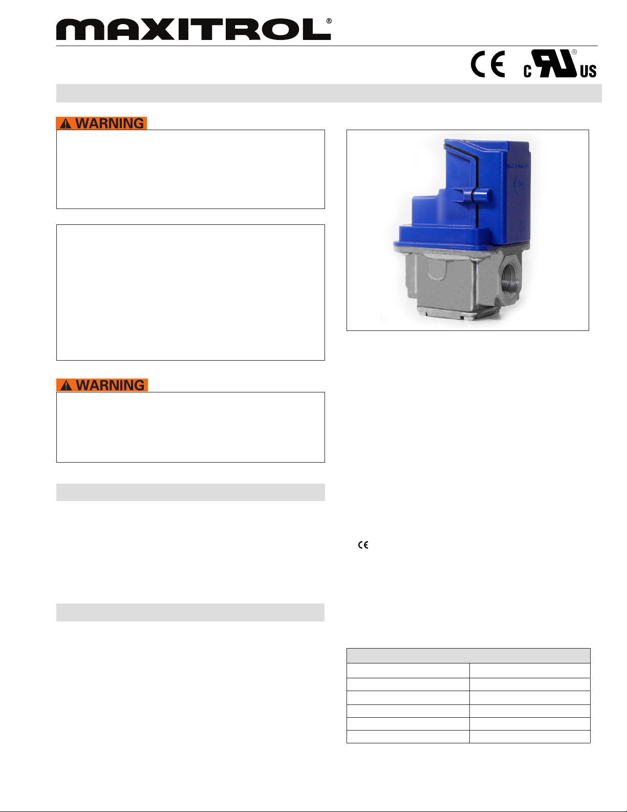
Figure 1: EXA STAR Modulating Valve Series
© 2011 Maxitrol
This control must be installed and operated strictly in accordance
with the instructions of the OEM and with all applicable government
codes and regulations, e.g. plumbing, mechanical, and electrical
codes and practices. These instructions do not supersede
OEM’s installation or operating instructions.
DESCRIPTION
The EXA STAR modulating valves are highly accurate and precise
modulating control valves (see Figure 1). EXA valves provide
repeatable process control with minimal hysteresis throughout the
entire range of modulation.
The EXA STAR modulation system’s high re setting and low re
setting are user programmable.
SPECIFICATIONS
Maximum Inlet Pressure: 5 psig
NOTE: Up to 10 psig available, consult Maxitrol Company.
Power Requirements: 24VAC/DC +/- 10% 50/60hz
NOTE: The EXA41, 51, 61 use half-wave rectiers. When using
a single transformer for powering the EXA41, 51, 61 and
devices with half-wave rectiers, the common for each must
be connected to the same leg of the transformer. Control
signal devices with full-wave bridge rectiers require a
separate transformer. See “Power Supply Compatibility”
bulletin.
Maximum Current Draw: 200mA
Temperature Limits: -40ºF to 150ºF operating
Control Signal (user selectable): 0-10VDC, 2-10VDC,
0-20mA, 4-20mA; 100KOhm Input Impedance
Mounting: Multipoise
Gases: Suitable for natural, manufactured, mixed gases,
liqueed petroleum gases, and LP gas-air mixtures.
Certications:
• EMC (EN 61000:2001)
• Immunity (EN 61000-6-2:2001)
• Emissions (EN 61000-6-4:2001)
• UL Recognized
•
Enclosure: IP40
Electrical Connection: UL310
Sizes: EXA41: 3/8”, 1/2” NPT or Rp ISO 7-1
EXA51: 1/2”, 3/4” NPT or Rp ISO 7-1
EXA61: 3/4”, 1” NPT or Rp ISO 7-1
Table 1: Capacity
Capacity @ 1” Pressure Drop - 0.64 sp. gr. gas:
EXA41 (3/8”) 190 cfh
EXA41 (1/2”) 215 cfh
EXA51 (1/2”) 385 cfh
EXA51 (3/4”) 435 cfh
EXA61 (3/4”) 670 cfh
EXA61 (1”) 780 cfh
© 2011 Maxitrol Company, All Rights Reserved.
1
Page 2
EXA STAR Modulating Valve Series
DESCRIPTION CONTINUED
The EXA STAR modulating valve series has a built-in digital
controller that provides a seamless interface with
controller.
a process
The valve has two (2) buttons and a communication LED for the
user interface. The buttons are used to set the valve for high and
low re settings (see Figure 4, page 4).
The valve has full open and full close mechanical limits. The
user can program settings that are within the valve’s mechanical
limits. This added dimension for sizing and applying the valve
is an important feature. It allows the valve to be set up for an
entirely different net output characteristic (dependent upon
supply pressure) (see Table 1, page 1).
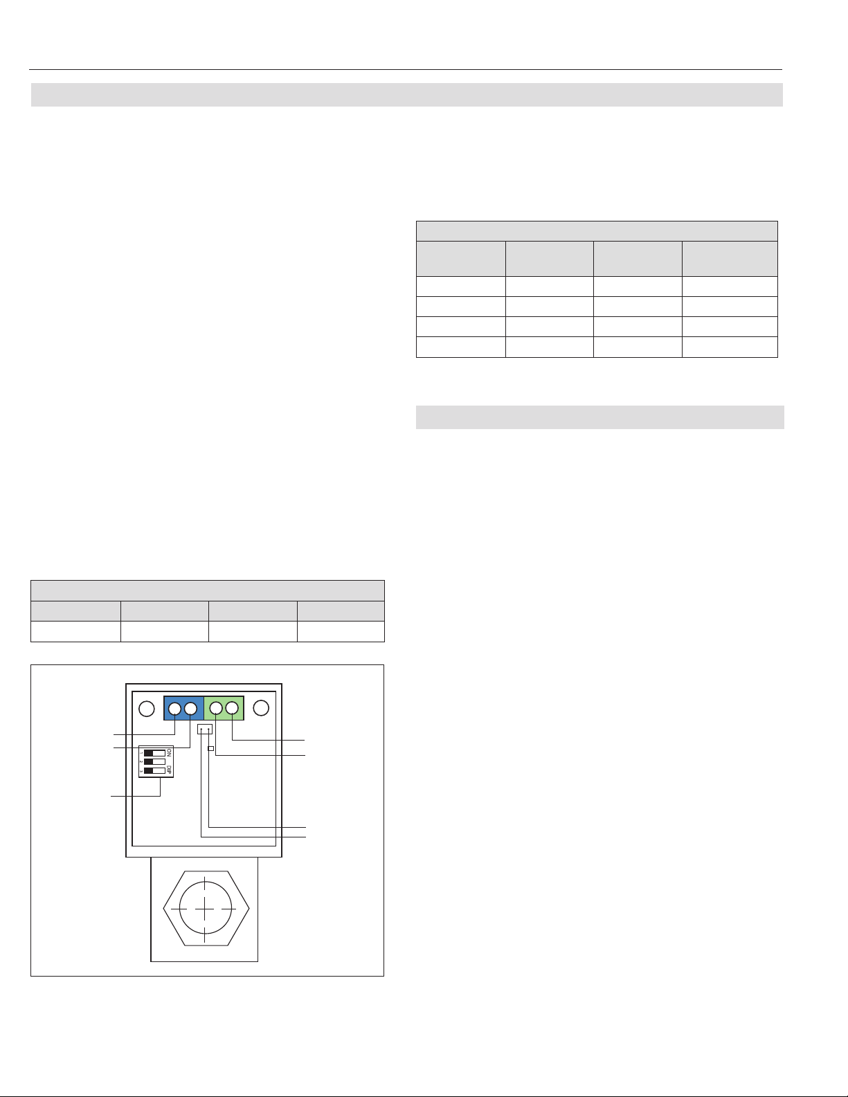
There are six (6) electrical connections on the EXA valve. Two (2)
are for power, two (2) are for the control signal, and two (2) are
for position feedback (see Figure 2).
Control Signal
The control signal indicates a position within the valve’s
programmed range of modulation.
NOTE: Control signal is polarity sensitive. Connect control
signal positive (+) to terminal 1 and control signal return
(-) to terminal 2 (see Table 2).
The control signal is “scaled” between the high and low re
setting of the valve. The minimum control signal will correspond
to the programmed low re setting, and the maximum control
signal will correspond to the programmed high re setting.
Table 2: Connection Table
Connection Table
Terminal 1 Terminal 2 Terminal 3 Terminal 4
Signal (+) Signal (-) Power (+) Power (-)
DIP Switches
A three (3) position DIP switch is located on the PCB (see Figure
2). Change the signal type and offset by changing the position of
DIP switches. (For DIP switch position and corresponding current/
voltage ranges, see Table 3).
Table 3: Dip Switch Position Table
DIP Switch Position Table
Control
Signal
SW1
Signal
SW2
Offset
SW3
Characteristic
0-10V OFF OFF OFF
2-10V OFF ON OFF
0-20 mA ON OFF OFF
4-20 mA ON ON OFF
POSITION FEEDBACK OUTPUT SPECIFICATION
The PWM output will give a feedback to correspond with the
current valve position between the programmed minimum and
maximum positions. The duty cycle range is always scaled from
the programmed minimum to the programmed maximum position.
Frequency: 200Hz ± 1Hz
Resolution: 9-bit (0.29% duty cycle)
Duty Cycle: 3% @ programmed minimum position
97% @ programmed maximum position
Output Impedance: 3.2kΩ ± 0.1kΩ
Control
Signal:
Terminal 1
Terminal 2
DIP Switches
(Table 3)
© 2011 Maxitrol
Figure 2: EXA STAR Modulating Valve Series Connections
© 2011 Maxitrol Company, All Rights Reserved.
Power:
Terminal 4
Terminal 3
Position
Feedback:
Pin 2
Pin 1
Output High Voltage: 5.0V nominal
5.25V maximum
NOTE: Output high level varies with the load current at the
PWM output.
Output Low Voltage: 0.0V + 0.01V
Pin 1: (-) negative polarity
Pin 2: (+) positive polarity
(see Figure 2)
Connection: TYCO MTA-100 or EQ.
(REF. 3-640442)
2
Page 3

EXA STAR Modulating Valve Series
C
D
B
A
F
SR
C
D
DIMENSIONS
NOTE: Dimensions are to be used only as an aid in designing clearance for the valve. Actual production dimensions may vary somewhat
from those shown (see Figure 3 and Table 4).
Table 4: Dimensions
Dimensions
inches (millimeters)
2.1
(54)
3.4
(87)
4.1
(105)
3.7
(94)
3.7
(94)
4.1
(105)
2.4
(61)
3.3
(84)
3.9
(100)
2.4
(61)
2.4
(61)
2.4
(61)
Model #
EXA41
EXA51
EXA61
Swing
Radius
(SR)
4.0
(102)
4.3
(110)
4.6
(117)
A B C D E F
4.8
(122)
5.5
(140)
6.0
(153)
1.0
(26)
1.3
(34)
1.5
(39)
SR
F
A
B
Figure 3: EXA STAR Modulating Valve Series Dimensions
D
E
C
© 2011 Maxitrol
© 2011 Maxitrol Company, All Rights Reserved.
3
Page 4

EXA STAR Modulating Valve Series
CONNECTIONS
Step 1: Remove 2 screws holding cover.
Step 2: Connect switched OFF 24V (AC/DC) power source to
terminals 3 and 4. Note polarity when using a DC
power source or if one leg of an AC transformer
secondary is externally grounded or is sharing power with
another half-wave device (see Figure 2, page 2).
Step 3: Set DIP switches to match available control signal
(see Table 3, page 2).
Step 4: Connect switched OFF control signal to terminals 1 and
2. Observe polarity.
Note that the return, or signal ground, must be connected
to terminal 2 (see Figure 2, page 2).
Step 5: Switch power and control signal ON.
Step 6: Set valve (see “Valve Setting” in section below).
Step 7: Replace cover.
VALVE SETTING
The EXA STAR modulating valve series has two (2) buttons and a
communication LED for the user interface. The buttons are used
to set the valve for high and low re settings (see Figure 4).
1. High Fire Setting (LED will be solid red)
2. Low Fire Setting (LED will be blinking red)
3. Operating Mode (LED will be OFF)
HIGH FIRE SETTING - BUTTON #1
To enter the high re setting mode, press and hold button #1 until
the LED lights solid red. Release. The valve is now in the high re
setting mode. Buttons #1 and #2 are used to set desired high re
setting.
Press or hold Button #1 to increase gas ow. Each button press
equates to the minimum available step size and will increase ow
slowly. Holding the button down auto steps and eliminates the need
to repeatedly press the button. Use this feature to rapidly increase
the ow.
Press or hold Button #2 to decrease gas ow. Each button press
equates to the minimum available step size and will decrease ow
slowly. Holding the button down auto steps and eliminates the need
to repeatedly press the button. Use this feature to rapidly decrease
the ow.
To save the high re setting, simultaneously hold Buttons #1 and #2
until the LED turns OFF.
NOTE: Controls left in any setting mode will default to the current
settings and return to normal operating mode after 5
minutes of inactivity.
LOW FIRE SETTING - BUTTON #2
To enter into the low re setting mode, press and hold button #2
until the LED light blinks red. Release. The valve is now in the low
re setting mode. Buttons #1 and #2 are used to set the desired low
re setting.
Button 1
Figure 4: EXA STAR Modulating Valve Series Adjustment Controls
Button 2
LED
© 2011 Maxitrol
Maxitrol Company
23555 Telegraph Rd., P.O. Box 2230
Southeld, MI 48037-2230 U.S.A.
EXAX1_MS_EN_08.2011
Press or hold Button #2 to decrease gas ow. Each button press
equates to the minimum available step size and will decrease ow
slowly. Holding the button down auto steps and eliminates the need
to repeatedly press the button. Use this feature to rapidly decrease
the ow.
Press or hold Button #1 to increase gas ow. Each button press
equates to the minimum available step size and will increase ow
slowly. Holding the button down auto steps and eliminates the need
to repeatedly press the button. Use this feature to rapidly increase
the ow.
To save the low re setting, simultaneously hold Buttons #1 and #2
until the blinking LED turns OFF.
NOTE: Controls left in any setting mode will default to the current
settings and return to normal operating mode after 5
minutes of inactivity.
www.maxitrol.com
© 2011 Maxitrol Company,
All Rights Reserved.
4
 Loading...