

Page 1
SERIES 44 INSTALLATION INSTRUCTIONS
and field service checklist
Table of Contents
Page 2 Introduction and Dimensions
Page 3 Specifications
Installation of Components
Typical Gas Trains
Page 4 & 5 Field Service Checklist
Page 6 Wiring Diagrams
Valve Adjustments
Page 7 Preliminary Circuit Analysis
Page 8 Temperature Calibration
Low Fire Start Time Adjustment
Sensitivity Adjustment
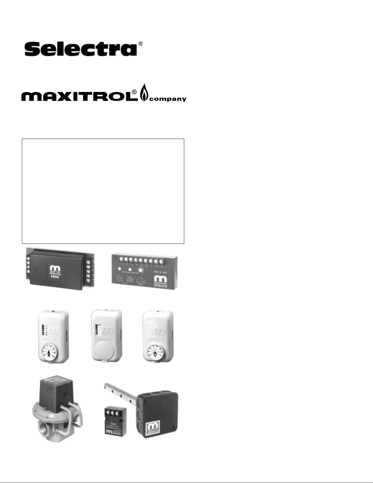
A1044L1 Amplifier
Selectrastat
Valve
Temp. Sensor
A1044 Amplifier
Temp. Selector
Mixing Tube and Sensor
BULLETIN MI2047-06/04
REPLACED MI1079
System Components
Amplifiers:
A1044 (min. 40° to 80° F/ max. 80° to 140° F)
A1044C (min. 20° to 60° F/ max. 80° to 140° F)
A1044D (min. 20° to 60° F/ max. 35° to 75° F)
A1044E (min. 20° to 60° F/ max. 60° to 120° F)
A1044L1, A1044CL1, A1044DL1, A1044EL1, A1044FL1 above ranges with adjustable low fire start duration
NOTE: Amplifier and Discharge Temperature Sensor must
have same temperature range to be compatible.
Discharge Temperature Sensors: use with Mixing Tube
TS144 (min. 40° to 80° F/max. 80° to 140° F)
TS144C (min. 20° to 60° F/max. 80° to 140° F)
TS144D (min. 20° to 60° F/max. 35° to 75° F)
TS144E (min. 20° to 60° F/max. 60° to 120° F)
TS144F (min. 40° to 60° F/max. 60° to 95° F)
Mixing Tubes: used with Sensors
MT1-9 or MT2-9 (9" length)
MT1-12 or MT2-12 (12" length)
MT1-23 or MT2-23 (23" length)
MT1-28 or MT2-28 (28" length)
MT1-57 (57" length)
Valves:
M411 (3/8" & 1/2" pipe size)
M511 (1/2" & 3/4" pipe size)
M611 (3/4" & 1" pipe size)
MR212D (1", 1¼", 1½ pipe size)
MR212E (1½" & 2" pipe size)
MR212G (2½" & 3" pipe size)
MR212J (4" flanged)
MR212D-2, E-2, G-2 & J-2 (same pipe sizes as MR212D-J
except used for 2-speed blower or dual fuel operation)
NOTE: M (Modulator) valve requires an upstream pressure
regulator for low fire & high fire settings.
MR (Modulator/Regulator) valve requires no
upstream pressure regulator up to 5 psi inlet.
Selectrastat (Senses & Selects):
T244 (55° to 90° F)
T244A (40° to 80° F)
or optional pair to replace Selectrastat:
Space Temperature Selector:
TD244 (wall mount 55° to 90° F)
TD244A (wall mount 40° to 80° F)
TD244P (panel mount 55° to 90° F)
TD244AP (panel mount 40° to 80° F)
Space Temperature Sensor:
TS244 (55° to 90° F)
TS244A (40° to 80° F)
NOTE: Space Temperature Selector and Space
Temperature Sensor must have same
temperature range to be compatible.
Page 2
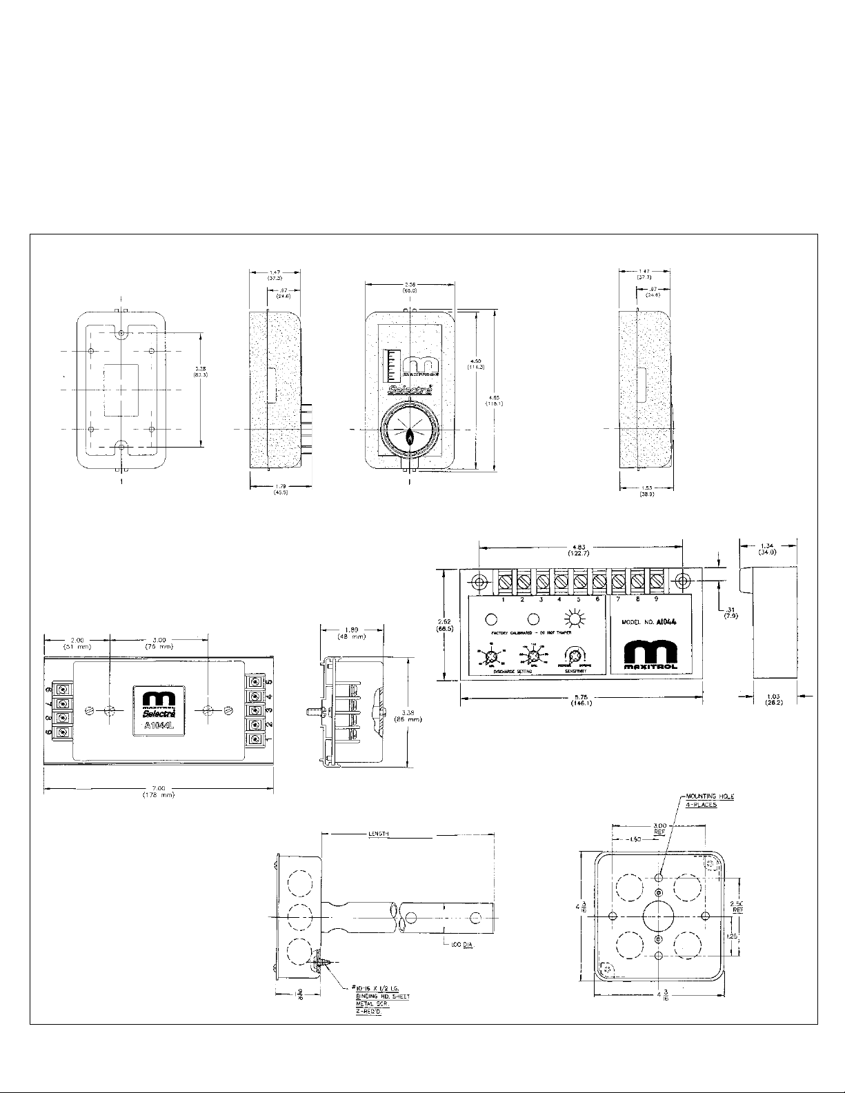
Introduction and Dimensions
Selectra SERIES 44 electronic gas flame modulation
systems are designed primarily for space heating, as
components of direct fired equipment. They may be
field installed on existing equipment or specified for new
equipment installation. All fuel gases are compatible.
The systems utilize Modulator or Modulator-Regulator
valves to control gas pressure. Amplifiers are available
with adjustable low-fire start duration.
SELECTRASTAT, TEMP. SELECTOR, SPACE TEMP. SENSOR
A discharge air temperature sensor (and mixing tube) is a
means of limiting the minimum and maximum discharge air
temperature. The amplifier supplies output voltage to the
modulating valve. A wall mounted Selectrastat senses
space temperature and has an integral selector with either
a 55° to 90° F or 40° to 80° F range. Optionally, a remote
Temperature Sensor paired with a separate Temperature
Selector can be substituted for the Selectrastat.
(Space Temperature Selector dimensions same)
A1044 AMPLIFIER
A1044L1 AMPLIFIER
(Space Temperature Sensor dimensions same except without front dial)
MIXING TUBE (TS144 attaches internally)
(SEE PAGE 1)
2
Page 3
Specifications
Pressure Adjustment Ranges: (Maximum Fire)
Standard (MR212) ................. 2" to 5" w.c. / 5 to 12 mbar
Standard (MR212-2) .............. 2" to 5" w.c. / 5 to 12 mbar
reduced 0" to 3" w.c. / 0 to 7.5 mbar
Vent: Model M411, M511, M611-vertical vent outlet 1/8"
NPT—12A06 installed.
MR212—two vents located in upper housing, both
equipped with vent limiting means.
Ambient Limits:
Operating -40° to 125° F / -40° to 52° C
Non-Operating -50° to 185° F / -46° to 85° C
Power Requirements: 24 Volts, NEC Class ll
transformer 20 VA
NOTE: Transformer secondary must not be grounded
in any portion of the circuit external to a Maxitrol
amplifier. If existing transformer is grounded, a
separate isolated transformer must be used. Electrical
Installation of Components
Wiring Run: Control wires connected to the Selectrastat,
Discharge Air Sensor, Remote Temperature Selector/
Sensor, Amplifier or Valve must not be run close to or
inside conduit with power or ignition wires. Doing so
may cause the unit to function erratically or may
destroy the amplifier. If shielded wires are used, shield
must be insulated and grounded at the amplifier location
only.
Amplifier: Install in any convenient location that is
protected from the weather and contaminated
atmosphere.
interference may effect performance and/or damage
equipment.
Gases: All fuel gases
Pressure Limits:
Maximum M411, M511, M611 Outlet Pressure: 7.0" w.c.
/17 mbar
MR212 Outlet Pressure Springs: 1" to 3.5" w.c. / 2.5 to 9
mbar, 2" to 5" w.c. / 5 to 12 mbar, and 3" to 8" w.c. / 7
to 20 mbar
Static Pressure Rating (M411, M511, M611 ) ..... 5.0 psi
/345 mbar
Maximum Operating Inlet Pressure (MR212) ...... 5.0 psi
/345 mbar
Maximum Emergency Exposure *(MR212)...... 12.5 psi
/862 mbar
*May not function properly at this pressure, but will suffer
no internal damage.
Selectrastat: This component selects and senses space
temperature. Remove cover to mount in heated area
where representative space temperature can be sensed.
Optional:
Remote Temperature Selector: Not temperature
sensitive (selects space temperature). Remove cover to
mount in any convenient location. Note: Temperature
selector and sensor must have same temperature range to
be compatible.
Remote Temperature Sensor: Senses space
temperature. Remove cover to mount in area where
representative space temperature is to be sensed.
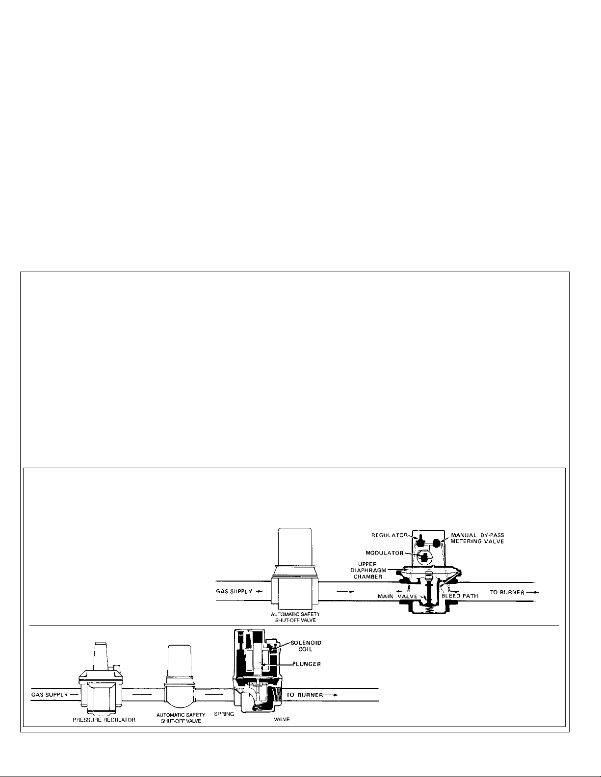
Typical Gas Trains
Modulator (M) or Modulator-Regulator (MR) Valve: Mount in upright position in horizontal run of pipe, downstream of
other controls - a separate gas pressure regulator must be used with any modulator (M) valve.
MR Valve: Modulator-regulator valve
M Valve: Regulator upstream of modulator valve
3
Page 4

head or repair wiring.
REMEDY
1. Install properly.
1. Arrow on side of valve should point in direction of gas flow.
on page 3).
2. If proper resistance values are not observed, replace modulator
3. Clean or replace plunger if necessary and install (as in figures
4. Replace diaphragm if ruptured.
MR212 (60-80 ohms), M611 (45-55 ohms).
solenoid sleeve.
2. Remove wires connected to amplifier terminals 6 & 7 and measure resistance.
3. Inspect - plunger should be installed (as in figures on page 3) and operate freely in
4. Disassemble valve for inspection of internal parts.
head or repair wiring.
5. Provide 24V AC to amplifier. Refer to item 24.
6. If proper resistance values are not observed, replace modulator
7. If readings are incorrect, replace the TS144 or repair wiring.
8. If power source and modulator coil check ot (items 5 & 6) but
wires 1 & 3, then 2 & 3. Meter should read greater than 2500 ohms.
5. Check for 24V AC at amplifier terminals 8 & 9.
6. Measure resistance per item 2.
7. Remove wires connected to amplifier terminals 1, 2, & 3. Measure resistance across
8. Follow precedures outlined in "PRELIMINARY CIRCUIT ANALYSIS" (Sections I & II).
proper modulating voltages cannot be obtained, then amplifier may
be assumed at fault. Install replacement amplifier.
filters & other inlet air restrictions. For other solutions, consult Maxitrol.
9. Adjust to proper low fire.
10. If greater than 1.5" negative pressure, check equipment for clogged
operating. Should be less than 1.5" w.c. negative pressure
9. See Valve Adjustments - Page 6.
10. Close main gas supply and measure manifold pressure with blower
repair wiring.
necessary - Pg. 8.
11. If amplifier is proven at fault, install replacement amplifier.
12. If reading is incorrect, replace the T244, TS244/TD244 or
13. If proper action is obtained, first check item 12. Recalibrate if
+ 1000 (T244).
+ 1000 (TS244) and 2100
+ 150 (TD244).
setting. Measure resistance across wires. Meter should read 6000 ohms
If TS244/TD244 are used, mete should read 4500 ohms
ohms
11. Follow precedures outlined in "PRELIMINARY CIRCUIT ANALYSIS" (Sections I & II).
12. Remove wires connected to amplifier terminals 4 & 5. Set T244 or TD244 to maximum
13. Follow procedures outlined in "PRELIMINARY CIRCUIT ANALYSIS" (Sections IV).
Temperature calibration procedures - Page 8.
14. Move TS144 to location where average temperature can be sensed.
15. If proper temperatures are not observed, refer to Discharge Air
14. Compare sensed temperature reading at TS144 with average discharge air temperature.
15. Follow precedures outlined in "PRELIMINARY CIRCUIT ANALYSIS" (Sections IV).
Consult Maxitrol about possibility of using special spring to
reduce pressure drop on selected installations.
19. Increase inlet pressure if possible or change to larger valve.
16. Clean, replace valve and/or seat if necessary.
16. Remove bottom Plate and inspect valve and seat
18. If readings are incorrect, replace the TS144 or repair wiring.
17. Clean, or if necessary, replace plunger.
18. Measure resistance per item 7.
17. Inspect - plunger should be smooth and clean and operate freely in solenoid sleeve.
20. See valve adjustments - page 6.
Pressure should be at least equal to the sum of: outlet pressure setting and pressure
drop of the valve (See Maxitrol Capacity Chart Bulletin) plus 1.0" w.c.
equipment manufacturer.
19. Read inlet pressure at valve, using a manomete with heater operating at full fire.
20. Read outlet pressure using manomete and compare with recommendation of
repair wiring.
necessary - page 8.
repair wiring.
21. If amplifier is proven at fault, install replacement ampifier.
22. If reading is incorrect, replace the T244, TS244/TD244 or
23. If proper aciton is obtained, first check item 22. Recalibrate if
24. If proper resistances are not observed, replace modulator head or
21. Follow precedure outlined in "PRELIMINARY CIRCUIT ANALYSIS" (Sections I & II).
22. Measure resistance per item 12.
23. Follow precedures outlined in "PRELIMINARY CIRCUIT ANALYSIS" (Section IV).
24. Measure resistance per item 2.
25. If desired temperature is not reached, increase maximum
25. Check to see if heater is delivering air at maximum discharge air setting.
dischage air temperature setting.
discharge air temperature setting.
fire, it may be indersized. Consult equipment manufacturer.
recalibrate if necessary.
26. If desired space temperatue is not reached, decrease minimum
27. If desired space temperature is not reached with heater at high
28. If temperature reading is incorrect, check items 25, 26 & 27, then
reading with T244 or TD244 dial setting.
26. Check to see if heater is delivering air at minimum discharge air setting.
27. Check to see if heater is operating at high fire.
28. Place thermometer next to T244 or TS244. Compare space temperature
POSSIBLE CAUSE FIELD TEST
1. Valve improperly installed.
2. Open circuit in modulator coil.
3. Plunger missing, jammed or improperly installed.
4. Ruptured main or balancing diaphragm.
Continuous low fire
(electronics OK).
No gas flow.
SYMPTOM
A.
Field Service Checklist
B.
5. No voltage to the amplifier.
6. Short in modulator coil circuit.
7. Short in TS144 circuit.
8. Faulty amplifier
Continuous Low Fire
(electronics problem).
C.
14. Improper TS144 location.
10. Excessive negative burner pressure.
Incorrect Low Fire. 9. Incorrect by-pass metering valve adjustment.
D.
11. Faulty amplifier.
12. Short in T244 or TS244/TD244 circuit.
13. Incorrect space temperature calibration.
Continuous
Minimum Discharge Air
Temperature.
E.
15. Incorrect discharge air temperature calibrations.
Incorrect Max. or Min.
Discharge Air Temperature.
F.
4
16. Foreign material holding valve open.
Continuous High Fire.
G.
18. Open circuit in TS144.
17. Plunger jammed.
(electronics OK)
Continuous High Fire.
H.
19. Inlet pressure too low.
20. Incorrect outlet pressure adjustment.
Incorrect High Fire.
(electronics problem)
I.
21. Faulty amplifier.
22. Open circuit in T244 or TS244/TD244.
23. Incorrect space temperature calibration.
Discharge Air Temperature.
J. Continuous Maximum
24. Short in modulator coil circuit.
K. Burned out Transfromer. No
25. Incorrect maximum discharge air temperature
Voltage to Amplifier.
L. Incorrect Space
setting A1044).
setting (A1044).
26. Incorrect minimum discharge air temperature
27. Insufficient burner capacity.
28. Incorrect space temperature calibration.
Temperature.
*Control circuits external to the Series 44 can cause burner malfunction. Always check manual valve to be certain gas is on, and check limit controls for normal operation.
Page 5

Amplifier with Selectrastat
Wiring Diagrams
Amplifier with remote temperature sensor and
separate temperature selector
TS144
MT1-12
TS144
MT1-12
VALVE
TRANS.
T244
TS244
TD244
TRANS.
VALVE
(Terminal locations shown for A1044 [and C, D, E] model amplifiers.
A1044L1 [and CL1, DL1, EL1] model terminal blocks 1-5 and 6-9 are at opposite ends of the board)
Valve Adjustments
(See bulletin MT2035 for additional M/MR valve information)
NOTE: Low fire adjustment should be checked whenever the high fire adjustment is changed.
MR 212 VALVE
M411, 511, 611 VALVE
High Fire Manifold Adjustments:
1. Disconnect wires from amplifier terminal #2 & #4.
This causes the valve to go to continuous high fire.
2. Remove seal cap (A), and turn
regulator pressure adjusting
screw to obtain desired manifold
pressure. (Clockwise rotation
increases pressure.)
3. Reconnect the wires to amplifier
terminal #2 & #4.
NOTE: If low fire bypass is on
maximum, the desired high fire
outlet pressure may not be
achieved.
Low Fire or Bypass Adjustments:
1. Disconnect wire from amplifier terminal
#8, this causes valve to go to continuous low fire.
2. Remove cap (B), and loosen lock screw (C). Turn (D)
to desired low fire adjustment. (Clockwise rotation
reduces minimum flow rate.)
3. Tighten set screw (C), replace cap (B) and reconnect
wire to amplifier terminal #8.
High Fire Manifold Adjustments:
1. Disconnect wires from amplifier terminal #2 & #4, this
causes the valve to go to continuous high fire.
2. Adjust the upstream pressure regulator to obtain the
desired manifold
pressure
(7" w.c. maximum).
3. Reconnect the wires
to amplifier terminal
#2 & #4.
B
Low Fire or Bypass
Adjustments:
1. Disconnect wire from
amplifier terminal #8,
this causes the valve
A
to go to continuous low fire.
2. Remove cap (A), and turn adjusting screw (B) to
desired low fire adjustment. (Clockwise rotation
reduces minimum flow rate.)
3. Replace cap (A), and reconnect wire to amplifier
terminal #8.
5
Page 6

Preliminary Circuit Analysis
This Preliminary Circuit Analysis will provide identification
of faulty components, improper wiring or calibration, and
other difficulties when used with the tabulated Field
Service Checklist (pages 4 & 5).
Note: All voltages and resistance readings are
approximate.
Section I
1. Wire the system (per Figure 1 below).
2. Connect a DC voltmeter to amplifier terminals #6 & #7.
3. Turn the Test-Potentiometer to minimum resistance.
(2,000 ohms). The DC voltage should read 0 volts.
4. Turn the Test-Potentiometer slowly to maximum
resistance (12,000 ohms). The DC voltage should
gradually increase to at least 18 volts.
If proper voltages are observed continue on with
Section II.
If proper voltages are not observed, the problem is
identified with the Amplifier, the 24-volt AC power
supply, or the circuit connected to terminals #6 & #7.
Section II
1. Turn power OFF, wire system (per Figure 2 below), turn
power ON.
2. Turn Test-Potentiometer to minimum resistance, the
voltage should be 0 volts.
3. Turn Test-Potentiometer slowly to maximum
resistance, the DC voltage should gradually increase to
at least 18 volts.
If proper voltages are observed in both Sections I & II,
the amplifier is satisfactory.
If proper voltages are not observed, continue testing to
identify the difficulty. Faults may be identified with the
amplifier, the 24V power supply, or the circuit
connected to terminals #6 & #7. See Field Service
Checklist.
Section III
1. Observe burner flames and/or burner pressure as Test-
Potentiometer is turned through full range. Note: From
0-5 volts, heater should be at by-pass or low, 5-15 volts,
heater should respond with various input rates; beyond
15 volts, heater is at maximum input.
If proper operation is observed, continue procedure to
check operation of sensing and selecting components.
If proper operation is not observed, see Field Service
Checklist to test M or MR valves and connecting wiring.
Section IV
1. With proper voltages observed thus far and modulator
responding correctly, wire the system (see Figure 1
below), except have TS144 connected in place of
jumper. Set MIN temperature selector at least 10° F
above outdoor temperature. Set MAX
temperature selector
at mid-range. Heater
is now under control
by the
(or)
TS144 Discharge Air Monitor.
2. Turn Test-Potentiometer to maximum resistance,
delivered air temperature should be per MAX
temperature setting. Turn Test-Potentiometer to
minimum resistance, delivered air temperature
should be per MIN temperature setting.
If proper delivered air temperatures are observed,
the problem is identified with the space
Model
A1044L1
temperature sensing and/or temperature
selecting components and circuits. See Field Service
Checklist.
If proper delivered air temperatures are not observed,
check calibration. See Field Service Checklist.
Section V
1. After test, remove all test equipment and reconnect all
components.
2K
RESISTOR
JUMPER
MT1-12/TS144
10K TEST
POT
VALVE
24V20VA
TRANS.
10K TEST POT
2K
RESISTOR
JUMPER
VALVE
14V20VA
TRANS.
(Terminal locations shown for A1044 [and C, D, E] model amplifiers.
A1044L1 [and CL1, DL1, EL1] model terminal blocks 1-5 and 6-9 are at opposite ends of the board)
6
Figure 2Figure 1
Page 7

Temperature Calibration
Note: All electronic components are pre-calibrated to a base
resistance. This permits field replacement without upsetting
system calibration.
Minimum Discharge Air Temperature
1. Install a thermometer or other temperature measuring
device at a point adjacent to the tip
of the TS144.
2. Connect a wire jumper between
terminals #4 and #5. Be sure
minimum temperature setting is at
least ten degrees higher than outdoor
temperature.
3. Turn the calibrating potentiometer
(A) until the reading of the
thermometer adjacent to the
TS144 agrees with the minimum
setting of the Discharge Air
Temperature Selector. Clockwise
rotation increases temperature
(A1044L model adjusted from blue
side).
4. Remove jumper.
Maximum Discharge Air Temperature
1. Install a thermometer or other temperature measuring
device at a point adjacent to the tip of the TS144.
2. Disconnect wires from terminals #4 & #5. Connect 12K
resistor across terminals #4 & #5.
Low Fire Start Time Adjustment
On A1044L1 (CL1, DL1, EL1) amplifiers, the low fire start
duration is adjustable from approximately 0-30 seconds,
and begins timing after the amplifier has been energized.
High fire is delayed, and the M/MR valve remains in the
low fire setting position during the delay time period.
Use a small screwdriver to adjust the time delay
potentiometer.
Turn clockwise (+) to increase low fire start duration, and
counter-clockwise (-) to decrease low fire start duration.
Time delay
potentiometer
A1044L1 (CL1, DL1, EL1)
cover removed
Sensitivity adjustment
3. Turn the calibrating potentiometer (B), until the reading
of the thermometer adjacent to the TS144 agrees with
the maximum setting of the Discharge Air Temperature
Selector. Clockwise rotation increases temperature
(A1044L1 model adjusted from blue side). Be sure
temperature setting does not exceed the design
temperature rise of the heater.
4. Remove resistor and reconnect
wires.
Space Temperature
1. Install a thermometer or other
temperature measuring device at a
point adjacent to the T244 or the
TS244. Set the T244 or the TD244
(whichever is used) for the desired
room temperature. Because of the
large space being heated, wait at
least one half hour* to make certain
adjustment is needed.
2. If the temperature reading is
different from the temperature setting,
turn (C) clockwise for an increase in
space temperature and counterclockwise for a decrease in
temperature. Each increment on adjustment C is
approximately 2.5 degrees (A1044L1 model adjusted from
blue side). After an adjustment has been made, give the
room temperature at least one half hour* to settle out
before rechecking.
* One half hour is only a time estimate. Longer or shorter
periods may be required for the temperature to stabilize.
Be sure space temperature is stabilized before attempting
calibration!
Sensitivity Adjustment
The sensitivity control will allow the user to control the
response of the system. Caution should be exercised in
the use of this adjustment. Under normal usage the
pointer should be located on the mark of the label.
If hunting is encountered (rapid oscillation), rotating the
sensitivity control counterclockwise may dampen the
oscillation, stabilizing the flame.
DO NOT adjust unless
A1044 (C, D, E)
model amplifier
necessary, because
decreasing the sensitivity will
increase the temperature
"DROOP" of the system.
7
Page 8

A copyrighted publication of
www.maxitrol.com
23555 Telegraph Rd., P.O. Box 2230
Maxitrol Company
Southfield, MI 48037-2230 U.S.A.
248.356.1400 • Fax 248.356.0829
European Representatives
Warnstedter Strasse 3 06502 Thale, Germany
49.3947.400.0 • Fax 49.3947.400.200
Industriestrasse 1 48308 Senden, Germany
49.2597.9632.0 • Fax 49.2597.9632.99
 Loading...