

Page 1
Series 14 & 44 Condensed Catalog
Electronic Modulation Gas-Fired Temperature Controls/Direct Fired Applications
DESCRIPTION
Selectra ® systems from Maxitrol maintain precise, stable
gas-red temperatures. Selectra’s unique electronic
Modulator or Modulator-Regulator valves control gas ow
with instantaneous response and continual adjustment.
They are the superior alternative to mod motors and
buttery valves.
OEM or retrot applications include environmental climate
control, as well as industrial or commercial heating
processes. Standard temperature adjustment range is 55º
to 90ºF. All fuel gases are compatible with capacities up to
30,000,000 Btu/h.
Available standard companion electronics include
temperature selectors, ampliers, and temperature
sensors, in a variety of congurations. The amplier
supplies output voltage to the M/MR valve (see Figure 1).
MAKE UP AIR APPLICATIONS
Series 14 System
Selectra ® Series 14 systems are designed primarily
for make-up air heating, as components of direct red
equipment.
A discharge air temperature sensor is mounted within a
mixing tube housing.
Ampliers are available with low-re start duration and
integral or remote temperature selection.
Options:
• A room override thermostat provides space tempera-
ture control by raising the discharge air temperature to
a preselected point - when used in conjunction with the
remote temperature selector.
• An inlet air sensor (and mixing tube) provides inverse
change in discharge air for each degree change in
inlet air - when installed in a convenient duct location
upstream of the burner.
• A dual temperature selector replaces TD114 to provide
dual control for door heaters or other applications such
as paint spray booths.
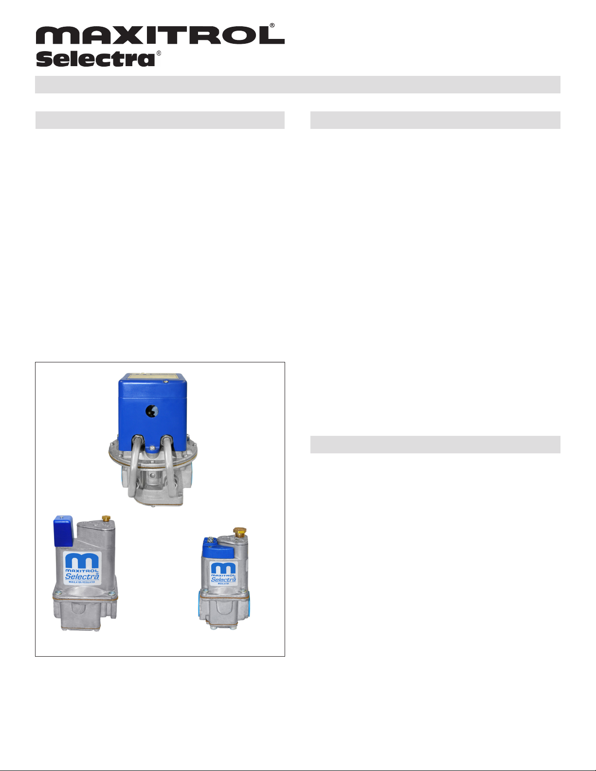
MR212
M611 M411
Figure 1: M/MR Valves
© 2011 Maxitrol Company, All Rights Reserved
SPACE HEATING APPLICATIONS
Series 44 System
Selectra ® Series 44 systems are designed primarily for
space heating, as components of direct red equipment.
A wall mounted Selectrastat ® senses space temperature
and has an integral selector with either a 55º to 90ºF or 40º
to 80ºF range. A discharge air temperature sensor (and
mixing tube) is a means of limiting the minimum and maximum discharge air temperature.
Ampliers are available with low-re start duration feature.
Option:
• Instead of a Selectrastat, a separate remote tempera-
ture sensor and selector can be substituted.
1
Page 2
MAKE UP AIR APPLICATIONS - Series 14 System
Series 14 Basic System Options
Valves
M411, M511,
M611,
MR212D, E,
G, or J
(see pg. 4)
Amplier or
Amplier-Selector
A1014R
AD1214 Dual Integral __ TS214/ MT1 or 2 __ __
Selection
Method
Single Remote TD114 TS114/ MT1 or 2 T115 TS10765
Dual Remote
Single Integral __ TS114/ MT1 or 2 __ TS10765
Remote Selector Model
(if applicable)
TD114HD TS114/ MT1 or 2
TD214 TS214/ MT1 or 2
NOTE: Selector and sensor must have the same temperature range to be compatible.
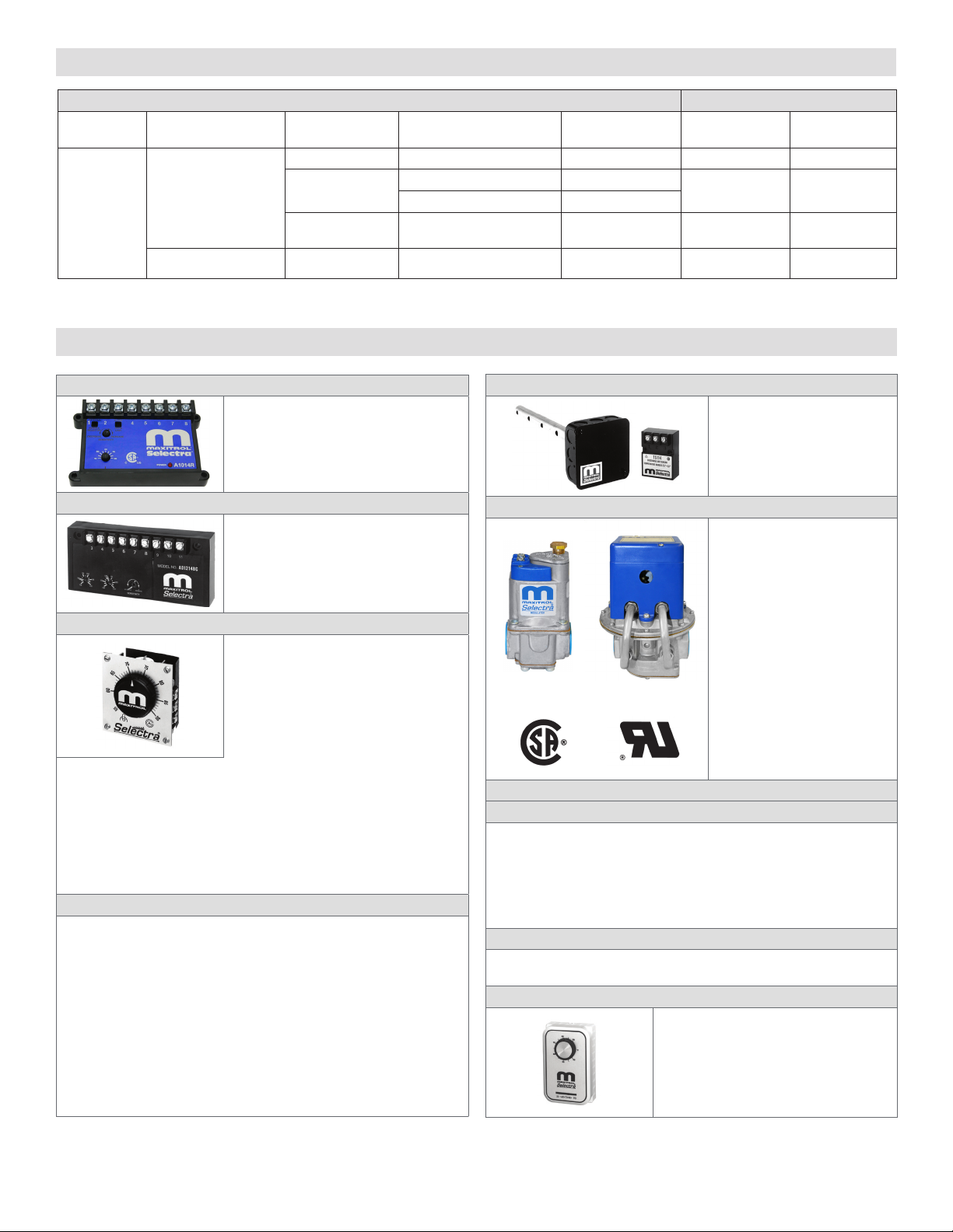
SYSTEM COMPONENTS
Sensor Override Stat
__ __
Inlet Air
Sensor
Amplier
A1014R
Dual Temperature Amplier-Selectors: (AD1214 shown)
AD1214__ (integral dual selector - any
comb. of 2 standard ranges avail.)
Example1 - AD1214BC (120° to 170°F
and 160° to 210°F), use w/TS214BC
Example2 - AD1214AD (80° to 130°F
and 200° to 250°F), use w/TS214AD
Remote Temperature Selectors
TD114 (55° to 90°F w/override 0° to 40°
over set point)
TD114A (80° to 130°F)
TD114A-1 (80° to 130°F w/ override 0° to
40°F over set point)
TD114B (120 to 170°F)
TD114C (160° to 210°F)
TD114D (200° to 250°F)
TD114E (100° to 250°F)
TD114F (40° to 80°F w/override 0° to 40° over set point)
TD114G (90° to 140°F)
TD114-1 (55° to 90°F w/120° to 170°F override) * use w/TS114
TD114-2 (55° to 90°F w/two outputs)
TD114G-2 (90° to 140°F w/two outputs)
NOTE: Remote Selector and Discharge Temperature Sensor must have
same temperature range to be compatible.
Optional: ETD-1 enclosure, EFP-1 cover plate only - no enclosure
Discharge Air Temperature Sensors: use with Mixing Tube
TS114 (55° to 90°F)
TS114A (80° to 130°F)
TS114B (120° to 170°F)
TS114C (160° to 210°F)
TS114D (200° to 250°F)
TS114E (100° to 250°F)
TS114F (40° to 80°F)
TS114G (90° to 140°F)
TS114J (110° to 160°F) To be used w/ AD1014-1116
TS214__ (dual sensor - any combination of 2 standard ranges available)
Example 1 - TS214G (55° to 90°F and 90° to 140°F, use w/TD114 & TD114G,
or TD214G [selector w/switch], or AD1214G)
Example 2- TS214AD (80° to 130°F and 200° to 250°F, use w/TD114A &
TD114D, or TD214AD [selector w/ switch], or AD1214AD)
Mixing Tubes: (and sensor)
Lengths:
MT1-9 or 2-9............................9”
MT1-12 or 2-12.....................12”
MT1-23 or 2-23.....................23”
MT1-28 or 2-28.....................28”
MT1-57...................................57”
Valves
Pipe Sizes:
M411........................... 3/8” & 1/2”
M511...........................1/2” & 3/4”
M611...........................3/4” & 1”
MR212D............1”, 1-1/4”, 1-1/2”
MR212E.....................1-1/2” & 2”
MR212G.....................2-1/2” & 3”
MR212J.......................4” Flanged
MR212-2D, E, G, J ..........(used
for 2-speed blower or dual fuel
operation)
NOTE: M (Modulator) valve
requires a pressure regulator for
high re setting. MR (ModulatorRegulator) valve requires no
pressure regulator up to 5 psi.
(See Bulletin MMR_MT_EN).
OPTIONAL SYSTEM COMPONENTS
Dual Temperature Selector
DOOR HEATERS: TD114HD use w/TS114 (door closed 55° to 90°F/
open 90° to 140°F)
PAINT SPRAY BOOTHS OR OTHER DUAL APPLICATIONS:
TD214__ (dual selector w/switch - any comb. of 2 standard ranges avail.)
Example 1- TD214G (55° to 90°F [spray] and 90° to 140°F [dry], use w/TS214G
Example 2 - TD214AD (80° to 130°F and 200° to 250°F, use w/TS214AD
TD214__X (same as TD214__, less enclosure)
Inlet Air Temperature Sensors: use with Mixing Tube
TS10765A (8:1 ratio); TS10765B (5:1 ratio); TS10765C (3.5:1 ratio)
Override Stat: (use only with TD114, F ,-1, A-1)
T115 (40° to 90°F)
© 2011 Maxitrol Company, All Rights Reserved
2
Page 3

SPACE HEATING APPLICATIONS - Series 44 System
Series 44 Basic System Options
Valves Amplier Selectrastat
M411, M511, M611,
MR212D, E, G, or J
(see pg. 4)
A1044, A1044U T244 TS144 / MT1 or 2 TD244 TS244
Discharge Temp.
Sensor
NOTE: Selector and sensor must have the same temperature range to be compatible.
SYSTEM COMPONENTS
Space Temperature
Selector
Space Temperature
Sensor
Ampliers
A1044U (replaces all A1044L1, suitable
replacement for A1044 [C,D,E,H]) (includes
0, 10, or 20 second low re start capability.)
A1044U
A1044 Amplier
Discharge Temperature Sensors: use with Mixing Tube
A1044UF (replacement for A1044FL1)
A1044UG (replacement for A1044G[L1])
A1044 (min. 40° to 80°F/ max. 80° to 140°F)
A1044C (min. 20° to 60°F/ max. 80° to 140°F)
A1044D (min. 20° to 60°F/ max. 35° to 75°F)
A1044E (min. 20° to 60°F/ max. 60° to 120°F)
A1044G (min. 40º to 80°F / max. 160º to 210°F)
A1044H (min. 40º to 80°F / max. 100º to 160°F)
NOTE: Amplier and Discharge Temperature Sensor must have same temperature
range to be compatible.
Sensors compatible with A1044U:
TS144 (min. 40° to 80°F/max. 80° to 140°F)
TS144C (min. 20° to 60°F/max. 80° to 140°F)
TS144D (min. 20° to 60°F/max. 35° to 75°F)
TS144E (min. 20° to 60°F/max. 60° to 120°F)
TS144H (min. 40º to 80°F / max. 100° to 160°F)
Valves
Pipe Sizes:
M411.......................................3/8” & 1/2”
M511.....................................1/2” & 3/4”
M611......................................3/4” & 1”
MR212D.......................1”, 1-1/4”, 1-1/2”
MR212E................................1-1/2” & 2”
MR212G................................2-1/2” & 3”
MR212J...................................4” Flanged
MR212-2D, E, G, J ..........(used for 2-speed
blower or dual fuel operation)
NOTE: M (Modulator) valve requires a
pressure regulator for high re setting. MR
(Modulator-Regulator) valve requires no
pressure regulator up to 5 psi. (See Bulletin
MMR_MT_EN).
Selectrastat (Senses and Selects)
T244 (55° to 90°F)
T244A (40° to 80°F)
or optional pair to replace
Selectrastat
Space Temperature Selector
Sensors compatible with A1044UF:
TS144F (min. 40° to 80°F / max. 60° to 95°F)
Sensors compatible with A1044UG:
TS144G (min. 40° to 80°F / max. 160° to 210°F)
Mixing Tubes: used with sensors
MT1-9 or 2-9..........................................9”
MT1-12 or 2-12.....................................12”
MT1-23 or 2-23.....................................23”
MT1-28 or 2-28.....................................28”
MT1-57..................................................57”
© 2011 Maxitrol Company, All Rights Reserved
Lengths:
TD244 (wall mount 55° to 90°F)
TD244A (wall mount 40° to 80°F)
TD244P (panel mount 55° to 90°F)
TD244AP (panel mount 40° to 80°F)
Space Temperature Sensor
TS244 (55° to 90°F)
TS244A (40° to 80°F)
NOTE: Space Temperature Selector
and Space Temperature Sensor
must have same temperature range
to be compatible.
3
Page 4

DIMENSIONS: inches(millimeters)
M/MR Valves
Model
Number
M411
M511
M611
MR212D
Swing
Radius
3.1
(79)
4.3
(109)
7.2
(183)
8.1
(206)
A B C D
3.9
(100)
5.3
(135)
7.4
(188)
10.2
(259)
Call-Outs
2
(51)
3.25
(83)
3.9
(99)
7
(178)
2.1
(54)
3.4
(86)
4
(102)
5.5
(140)
.9
(24)
1.2
(30)
1.5
(37)
2.3
(59)
B
B
C
C
M411, 511
A
A
A
D
D
B
B
C
C
A
D
D
M611
MR212E
MR212G
MR212J*
8.6
(218)
10.4
(264)
__ 24
11.25
(286)
14.75
(375)
(610)
9.1
(232)
13.5
(343)
21.5
(546)
8
(203)
11.75
(298)
13.9
(352)
3
(76)
4.6
(118)
5.9
(149)
NOTE: Dimensions are to be used only as an aid in designing clearance.
Actual production dimensions may vary somewhat from those shown
Series 14 System
Model Number Dimensions
A1014R Amplier 4.51” (115) x 2.62” (67) x 1.34” (34)
AD1214 Dual Temp.
Amplier-Selector
TD114 Remote Temp.
Selector
T115 Override Stat 2.96” (75) x 4.69” (119) x 2.56” (65)
ETD- 1 (opt. TD114
enclosure),
MT1 Mixing Tube encl.
(for sensor)
MT2 Mixing Tube enclosure
(for sensor)
5.75” (146) x 2.62 (67) x 1.34” (34)
2.62” (67) x 3” (76) x 1.75” (44)
4.19” (106) x 4.19” (106) x 1.88” (48)
Tube lengths:
9” (229), 12” (305), 23” (584), 28” (711),
57” (1448)
2.19” (56) x 4.19” (106) x 1.88” (48)
Tube lengths:
9” (229), 12” (305), 23” (584), 28” (711)
A
B
B
C
C
A
D
D
MR212(D, E, G, J)
Figure 2: M/MR Valve Call-Outs
Series 44 System
Model Number Dimensions
A1044 Amplier 5.75” (146) x 2.62” (67) x 1.34” (34)
A1044U Amplier 6” (152) x 3.38” (86) x 2” (51)
T244 Selectrastat 2.56” (65) x 4.5” (114) x 1.79” (46)
TD244 Space Temp. Selector 2.56” (65) x 4.5” (114) x 1.79” (46)
TS244 Space Temp. Sensor 2.56” (65) x 4.5” (114) x 1.53” (39)
MT1 Mixing Tube enclosure
(for TS144 sensor)
MT2 Mixing Tube enclosure
(for TS144 sensor)
19” (106) x 4.19” (106) x 1.88” (48)
Tube lengths:
9” (229), 12” (305), 23” (584), 28” (711),
57” (1448)
2.19” (56) x 4.19” (106) x 1.88” (48)
Tube lengths:
9” (229), 12” (305), 23” (584), 28” (711)
NOTE: Dimensions are to be used only as an aid in designing clearance. Actual production dimensions may vary somewhat from those shown
VALVE PRESSURE
M411, M511, M611 - CSA tested for 1/2 psi inlet pressure, Maxitrol tested for 1 psi maximum operating inlet pressure.
MR212D, E, G, J - CSA rated for 5 psi inlet pressure, Maxitrol tested for 5 psi maximum operating inlet pressure.
See Bulletin MMR_MT_EN for additional valve information.
Maxitrol Company
23555 Telegraph Rd., PO Box 2230
Southeld, MI 48037-2230
SEL1444_CC_EN.10.2011
4
www.maxitrol.com
© 2011 Maxitrol Company
All Rights Reserved
 Loading...