

Page 1
PC_CC_EN_06.2006
Replaced PC2094-8/01
© 2006 Maxitrol Company, All Rights Reserved
Product Catalog
Paktronics Controls Division
Page 2
Table of ContentsTable of Contents
Table of Contents
Table of ContentsTable of Contents
Trakstat®
Product Description................................................................................... 3
Specifications................................................................................................3
Wiring Diagram........................................................................................... 4
Dimensions...................................................................................................4
Pakstat® Series I
Product Description................................................................................... 5
Specifications................................................................................................ 5
Wiring Diagram.......................................................................................... 6
Calibration.................................................................................................... 6
Resistance Table for 1000 OHM Platinum Sensors.............................7
Pakstat® Series II
Product Description................................................................................... 8
Specifications................................................................................................ 8
Wiring Diagram........................................................................................... 9
Calibration..................................................................................................... 9
LCD3000 Digital Display................................................................. 10-11
Beta Series Electronic Temperature Controller
Product Description................................................................................ 12
Specifications............................................................................................. 12
Mounting Dimensions.............................................................................12
Temperature Controls Model Matrix............................................. 13-14
Troubleshooting Guide........................................................................... 15
Paktronics Controls Division
© 2006 Maxitrol Company, All Rights Reserved
®
Page 3
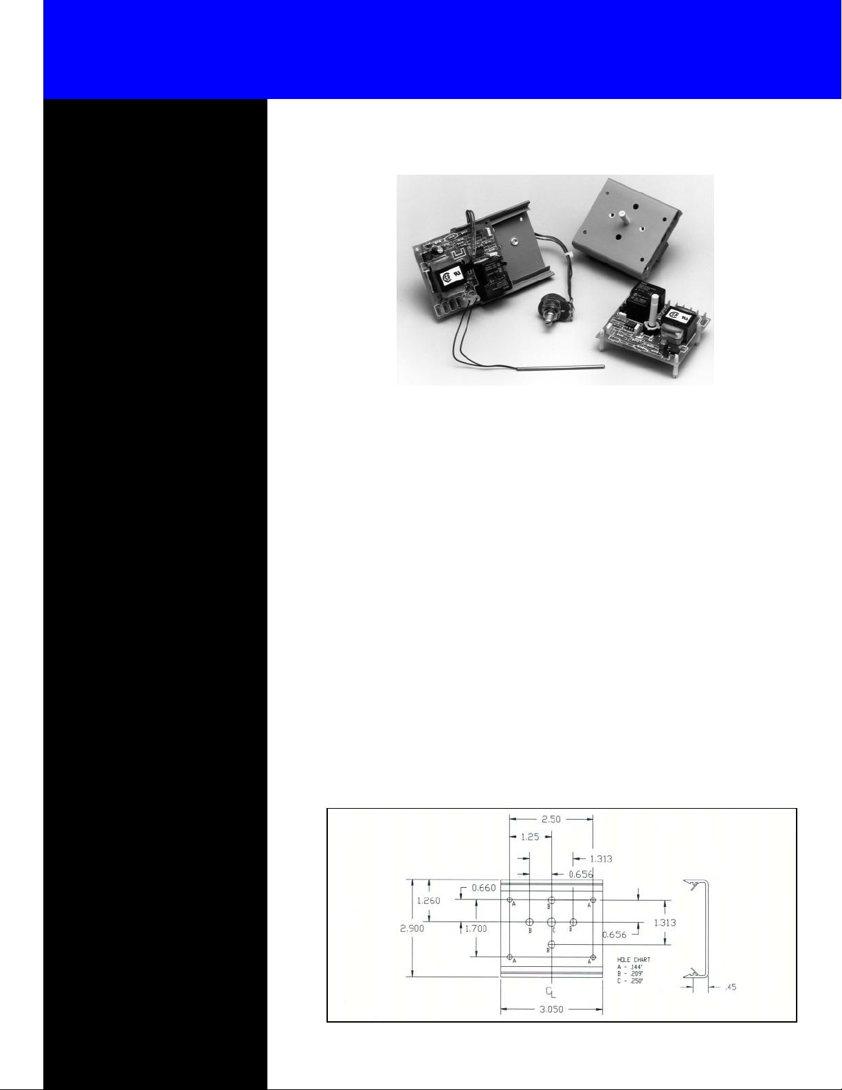
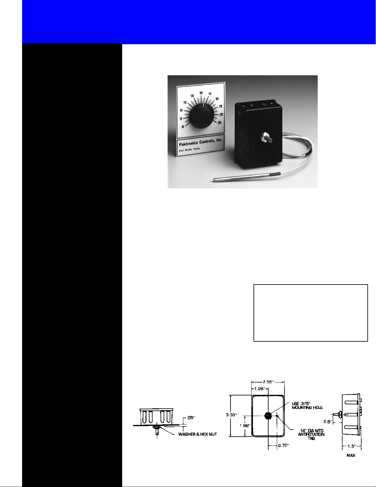
Trakstat Electronic Thermostat
Specifications
Input Voltage:
120 VAC
208/240 VAC ± 10%, 50/60
Hz.
Stability:
Better than ±1% of span or
±4°, whichever is greater.
± 10%, 50/60 Hz.
®
Static Deadband:
(nominal)
Operating Conditions:
Ambient Temperature:
0°C to +70°C
Relative Humidity: 5% to 95%
(noncondensing)
Output Options
Normally open (1 form A) relay
contact.
Relay Contact Ratings:
2 to 20 Amps at 12 to 240Vac,
resistive load. (RC Snubber recommended with inductive loads)
1 to 20 Amps at 5 to 28 Vdc*
(Arc suppression required)
Solid State Relay (SSR) Option:
Switched 24Vdc @ 30mA to
control external SSR.
±1°
Product Description
The Trakstat series of electronic thermostats,
by Paktronics, is a cost-effective alternative to
the use of mechanical and pneumatic controllers. The Trakstat’s design flexibility and economical packaging offer a quality electronic
thermostat which fits most original equipment
manufacturer’s (OEM) temperature control
requirements.
The Trakstat control can incorporate either a
resistance temperature device (RTD), thermistor sensor, or type J or K thermocouple.
Sensors of this type eliminate the problems
of capillary tube kinking and their calibration
is not affected by atmospheric pressure
changes.
Track Dimensions
The Trakstat’s versatile mounting capabilities
offer the OEM many options from which to
choose, including a factory-adjusted fixed
setpoint, snap-in control shaft, or remote potentiometer when panel space is limited. The
UL and CSA recognized 20 AMP output relay will handle most load requirements, or the
output can be configured to drive a solid state
relay. The quick connect terminals allow for
fast installation and service.
Accurate, repeatable temperature control
through a narrow deadband will result in better temperature control and a better product
for your
customers.
Control Operation:
ON/OFF control.
Heating version:
Load is turned OFF with temperature rise above set point.
Cooling Version:
Load is turned ON with temperature rise above set point.
NOTE: Other options are available. Please consult factory.
© 2006 Maxitrol Company, All Rights Reserved
3
Page 4
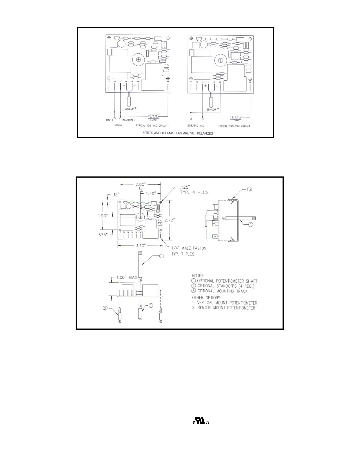
Wiring Diagram Trakstat
Trakstat Dimensions
Trakstat
♦ Accurate/Repeatable Setpoint
♦ 20 Amp Relay Output Rating
♦ Factory Calibration
♦ On/Off Control
© 2006 Maxitrol Company, All Rights Reserved
®
♦ Simple Installation
♦ Thermistor Sensor
♦ Platinum RTD Sensor
♦ Type J or K Thermocouple
♦
4
Page 5
®
Pakstat Series l Electronic Thermostat
Specifications
Input Voltage:
120 VAC
208/240 VAC ± 10%, 50/60
Hz.
Stability:
Better than ±1% of span or
±4°, whichever is greater.
± 10%, 50/60 Hz.
Static Deadband:
(nominal)
Operating Conditions:
Ambient Temperature:
0°C to +70°C
Relative Humidity: 5% to 95%
(noncondensing)
Output Options
Normally open (1 form A) relay
contact.
Relay Contact Ratings:
2 to 20 Amps at 12 to 240Vac,
resistive load. (RC Snubber recommended with inductive loads)
1 to 20 Amps at 5 to 28 Vdc*
(Arc suppression required)
Solid State Relay (SSR) Option:
Switched 24Vdc @ 30mA to
control external SSR.
±1°
Product Description
The PAKSTAT SERIES I electronic thermostat by Paktronics is a low cost alternative to the use of mechanical, pneumatic or
DIN packaged controllers. Part of the
PAKSTAT SERIES of OEM controls, the
PAKSTAT Series I offers a degree of flexibility and economy unavailable in other
packaged controls.
With its flexible wire sensor, the PAKSTAT
SERIES I controller eliminates the problems of capillary tube kinking and breakage. The quick connect terminals allow fast
installation and service.
The PAKSTAT SERIES I is used where it is
desirable to have accurate, repeatable temperature control through a narrow deadband.
The result is better temperature control and a
better product for your customer.
PAKSTAT is also available in digital indicating and cooling versions.
For more information, contact your
local PAKTRONICS representative or the factory.
Control Operation:
ON/OFF control.
Heating version:
Load is turned OFF with temperature rise above set point.
Cooling Version:
Load is turned ON with temperature rise above set point.
NOTE: Other options are available. Please consult factory.
© 2006 Maxitrol Company, All Rights Reserved
5
Page 6
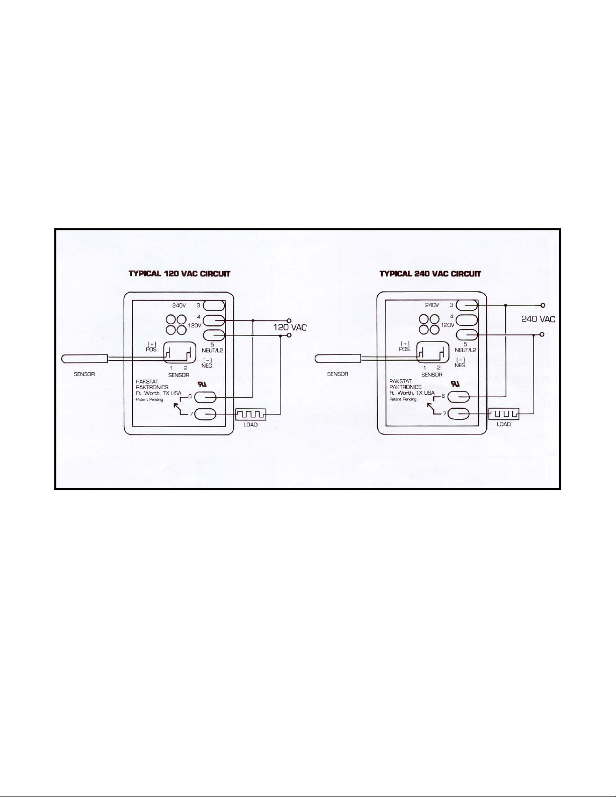
Wiring Diagram Pakstat Series I
1. Connect sensor leads to terminals 1 and 2. For
thermocouples, the red (negative) lead attaches to
terminal 2. (RTD SENSOR LEADS ARE NOT
POLARIZED).
2. For 120 VAC operation, connect LINE to terminals 4 and 5. For 208 to 240 VAC operation,
connect LINE to terminals 3 and 5.
3. Terminals 6 and 7 connect to an internal normally
open relay contact that is independent of the
controller’s operating voltage.
4. Connect AC line to load using external wiring, as
shown below.
Calibration Pakstat Series I
Simplified calibration decreases maintenance time without compromising accuracy. Our temperature controllers can be factory calibrated for convenience or calibrated as necessary at your facility.
1. Connect the PAKSTAT according to the wiring
diagram and instructions.
2. Attach the knob with the setscrews provided.
3. Turn the knob until the potentiometer is located at
the center of the dial.
4. Turn the power ON and allow 5 minutes for the
system to stabilize.
© 2006 Maxitrol Company, All Rights Reserved
Note: The control will be damaged if 208/240 VAC is
connected to terminals 4 & 5 or to terminals 3 & 4.
5. Measure the temperature with an accurate
thermometer next to the Pakstat sensor.
6. Loosen the knob setscrews and turn the knob,
without turning the potentiometer, until the dial is
set according to the thermometer reading.
7. Tighten the knob setscrews.
Calibration can now be performed on identical installations by noting the position of the potentiometer and
duplicating the setting. Offsets to compensate for sensor location can be calibrated. Contact the factory for
details.
6
Page 7

Resistance Table for 1000 OHM Platinum Sensors
RTD Units Only
Type J or K Thermocouple
© 2006 Maxitrol Company, All Rights Reserved
7
Page 8
®
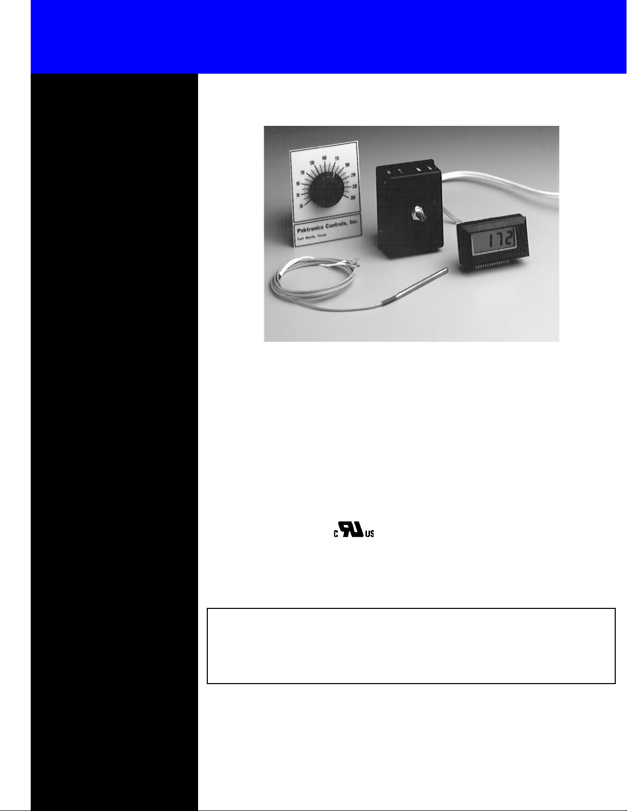
Pakstat Series ll Electronic Thermostat
Specifications
Input Voltage:
120 VAC
208/240 VAC ± 10%, 50/60
Hz.
Stability:
Better than ±1% of span or
±4°, whichever is greater.
± 10%, 50/60 Hz.
Static Deadband:
(nominal)
Operating Conditions:
Ambient Temperature:
0°C to +70°C
Relative Humidity: 5% to 95%
(noncondensing)
Output Options
Normally open (1 form A) relay
contact.
Relay Contact Ratings:
2 to 20 Amps at 12 to 240Vac,
resistive load. (RC Snubber recommended with inductive loads)
1 to 20 Amps at 5 to 28 Vdc*
(Arc suppression required)
Solid State Relay (SSR) Option:
Switched 24Vdc @ 30mA to
control external SSR.
±1°
Product Description
The PAKSTAT SERIES II is an upgraded version of its predecessor, the PAKSTAT
SERIES I.
When coupled with the model LCD3000 digital display, you can offer your customer
the convenience of digital indication of process temperature. The LCD3000 is a 3
digit display with resolution of 1°. Accuracy of 1%, ± one digit, meets most agency
requirements for food storage.
(on selected units)
½
Control Operation:
ON/OFF control.
Heating version:
Load is turned OFF with temperature rise above set point.
Cooling Version:
Load is turned ON with temperature rise above set point.
NOTE: Other options are available. Please consult factory.
NOTE: Pakstat is also available in non-indicating and cooling
versions. For more information, contact your local
PAKTRONICS representative or the factory.
© 2006 Maxitrol Company, All Rights Reserved
8
Page 9

Calibration
Simplified calibration decreases maintenance time without compromising accuracy. Our temperature controllers can be factory calibrated for convenience or calibrated, as necessary, at your facility.
1. Connect the PAKSTAT according to the wiring
diagram and instructions.
2. Attach the knob with the setscrews provided.
3. Turn the knob until the potentiometer is located at
the center of the dial.
Wiring Diagram
1. Connect sensor leads to terminals 1 and 2. For thermocouples, the red (negative) lead connects to terminal 2. (RTD’s and Thermistors are not polarized.)
2. For 120 VAC operation, connect LINE to terminals
4 and 5. For 208 to 240 VAC operation, connect LINE
to terminals 3 and 5. Note: The control will be
damaged if 208/240 VAC is connected to terminals 4 & 5 or to terminals 3 & 4.
3. Terminals 6 and 7 connect to an internal normally
open relay contact that is independent of the
controller’s operating voltage.
4. Connect AC line to load using external wiring.
5. Connect LCD3000 as shown.
Ordering Information
4. Turn the power ON and allow ample time for the
system to stabilize.
5. Note the temperature reading on the LCD3000
display.
6. Loosen the knob setscrew and turn the knob,
without turning the potentiometer, until the dial is
set according to the display reading.
7. Tighten the knob setscrews.
Calibration can now be performed on identical installations by noting the position of the potentiometer and
duplicating the setting. Offsets to compensate for sensor location can be callibrated. Contact the factory for
details.
© 2006 Maxitrol Company, All Rights Reserved
9
Page 10
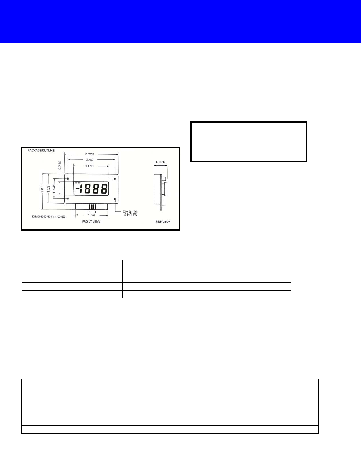
LCD3000 – Remote Mounted Digital Display
Product Description
The LCD3000 liquid crystal display is the ideal companion to Paktronics PAKSTAT SERIES II controllers.
The LCD3000, with its large ¾ inch display, offers high
readability in ambient light conditions and at wide viewing angles.
Specifications
Terminal Definitions
The remote mounting from the PC board allows you
to provide a custom look to your control panel, while
still using a standard product. The mounting is a simple
bezel arrangement.
LED DISPLAY ALSO
AVAILABLE
Selected models only—consult factory.
TERMINAL INPUT
1
2
3
4
IN LO
IN HI
V +
V –
DESCRIPTION
2V full scale input, if “IN HI” is lower than “IN LO”
display will show negative.
Positive power supply.
Negative power supply.
Absolute Maximum Ratings
Operating Voltage.................................................................15Vdc
Operating Temperature.................................................0 to 60°C
Storage Temperature..................................................-10 to 80°C
Electrical Characteristics TA = 25°C, RH below 80%
CHARACTERISTICS
Power Supply Voltage
Power Supply Current
Sampling Rate
Accuracy (Display Only)
Turn-on Voltage for “LO BAT” Indicator
Input Leakage Current (VIN = 0)
MIN
7
7
TYP
9
1.3
2.5
0.1% ± 1 digit
7.2
1
MAX
12
2.0
7.5
10
UNITS
Reading/Sec.
% ± digits
V
mA
V
pA
© 2006 Maxitrol Company, All Rights Reserved
10
Page 11
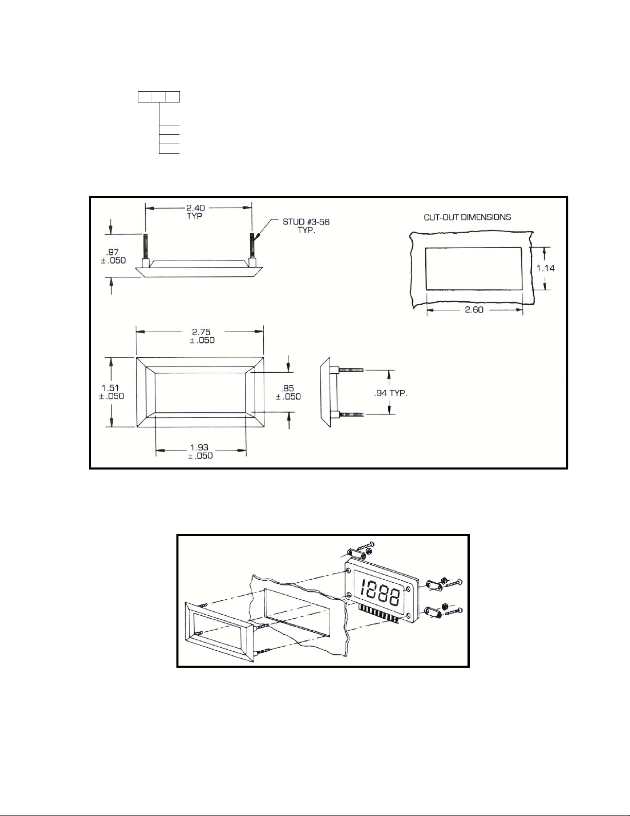
Ordering Information
Specify Model Number:
LCD3000
Configuration
001 24” connecting cable and complete bezel kit
002 5” connecting cable and complete bezel kit
003 24” connecting cable, no bezel
004 5” connecting cable, no bezel
Mounting
NOTE:
The following hardware accompanies the mounting bezel:
(A) #4-48 x 5/8” lg, phillips hd screw, (4).
(B) #3-56 nut, (4).
(C) fixing ears, (4).
DIMENSIONS IN INCHES
© 2006 Maxitrol Company, All Rights Reserved
11
Page 12
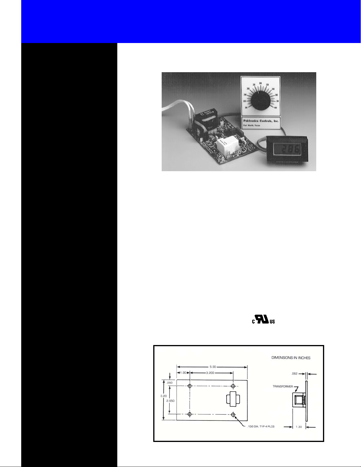
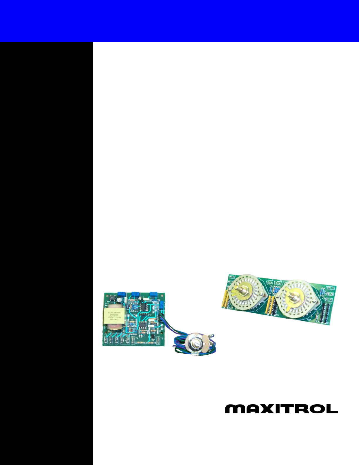
Beta Series Electronic Temperature Controller
Specifications
Input Voltage:
120/208/240 Vac
Hz.
Operating Conditions:
Ambient Temperature:
0°C to +70°C
Relative Humidity:
5% to 95% (non-condensing)
Control Options:
Refer to the Beta Series design matrix for common configuration options.
± 10%, 50/60
Product Description
For more information on how a
Beta Series controller can be configured for your application, contact your local Paktronics representative, or call Paktronics Controls at
(817) 284-5241.
The BETA SERIES open-architecture electronic temperature controls, by Paktronics,
offers a low cost alternative to the use of
inaccurate mechanical or pneumatic thermostats, and expensive panel mounted temperature controllers. The BETA SERIES controllers offer the flexibility of custom controls with the pricing and delivery of standard products.
When coupled with the model LCD3000
digital display, the BETA SERIES electronic
temperature controllers provide the convenience of digital indication of actual process
temperature.
Mounting Dimensions
The LCD3000 is a 3½ digit LCD display with
resolution of 1°. With its flexible wire sensor, the BETA SERIES of controllers eliminates the problems of capillary tube kinking
and breakage. The quick-connect terminals
allow fast installation and service.
The BETA SERIES of controllers is used
where it is desirable to have accurate, repeatable temperature control through a narrow
deadband.
(on selected units)
© 2006 Maxitrol Company, All Rights Reserved
12
Page 13
Temperature Controls Model Matrix...
B
STYLE
B BETA SERIES open board controls.
SETPOINT TYPE
2 Internal. An on-board, screw-
driver adjustable type pot.
INDICATION
1 None. Where constant temperature
monitoring is undesirable, or accomplished external to the controller.
5 Deviation Output. A bipolar (±) DC
output to drive an external deviation
indicator.
6 Display Output. 0-2 Vdc output to
drive a high impedance analog meter or
an LCD3000 digital display.
CONTROL MODE
A. On/Off (contacts open on temperature rise).
Generally used in heating applications where there
is a constant change in variables, such as load or
setpoint, in a static system. On/Off can be set
up with a very narrow deadband (or differential)
for tight control, or with a wide deadband for
use when mechanical limitations restrict cycling.
C. Fast Zero-Crossing Time Proportioning .25
second minimum cycle time (bandwidth is fieldadjustable to 10% of span). Proportioning may
be desirable in a dynamic system, where the load
(such as flow rate) and setpoint are constant.
6 Accepts remote-mounted
potentiometer.
7 Dual Internal. Two on-board
setpoints used in dual mode
controls
8 Accepts dual remote-mounted
potentiometers.
This matrix represents only the more common
configurations. The BETA SERIES custom
controls is limited only by your imagination.
Contact Paktronics Controls, or your local
Paktronics representative for additional information.
F. On/Off contacts close on temperature rise.
Generally used for cooling applications.
K. Zero Crossing Proportional, reverse acting.
L. Window controller. Used where controlling
action takes place when the process temperature
is within a specific range of temperatures. Can
also be made so that action occurs when temperatures are above or below the window. This
type of control might be used in an application
where heat would be called for if temperatures
fell below the window, and cooling if the
temperature exceeded the window.
© 2006 Maxitrol Company, All Rights Reserved
13
Page 14

Temperature Controls Model Matrix...
INPUT VOLTAGE
0 Other
3 120/208/240 VAC, user
selectable
4 24 VAC ± 10%, used where the
customer already has low voltage in
his cabinet/control panel
5 27 VDC
9 15 VDC
SECONDARY OUTPUTS (alarms)
0 None
1 Single SPST relay (tracking) with automatic reset.
Used as an over or under temperature alarm. Alarm
is set relative to the process temperature, and changes
along with any change in setpoint.
3 Dual SPST relays (tracking), automatic reset.
Used where over and under temperature indication is needed. Both alarm points may be set
above or below the setpoint.
4 Single SPST relay (tracking), manual reset.
7 Single SPST relay (absolute), automatic reset.
Used where an absolute over, or under, temperature condition must be protected. Alarms must
be changed each time the setpoint is changed.
8 Dual SPST relays (absolute), automatic reset.
PRIMARY OUTPUT
01 24 VDC, 30 mA. Used to drive an external
mechanical, or solid-state relay.
02 Dual 24 VDC, 30mA.
09 4-20 mA output to drive an external device
such as a transmitter.
10 1 amp Triac. Generally used to drive a line
voltage device such as a relay or solenoid.
17 Remote mounted 40 amp Triac can control
up to 30 amp resistive load (AC voltage only).
Note: Adequate heat sinking must be provided
by user.
18 20 amp isolated SPST normally open relay.
24 0.4 amp isolated SPST normally open relay
for use in driving contactors and coils.
9 Single SPST relay (absolute), latching.
NOTE: All alarm outputs rated at 0.4 amp
© 2006 Maxitrol Company, All Rights Reserved
25 Dual 20 amp SPST relay (window control).
26 Dual low current SPST relay (window control)
14
Page 15

Troubleshooting Guide
SYMPTOM POSSIBLE CAUSE
A. Unit will not turn the heater on.
B. Unit will not turn the heater off.
C. Unit is not controlling the temperature
at setpoint.
1. Control is not wired properly.
2. Control setpoint is too low.
3. Open sensor.
4. Control input power is not correct.
1. Control is not wired correctly.
2. Control setpoint too high.
3. Shorted sensor.
4. Sensor polarity (Thermocouple models only)
5. Control power.
6. Control cannot reach setpoint temperature.
1. Sensor placement.
2. Sensor placement.
TEST AND REMEDY
1. Connect the heater in series with the relay contacts. Please note
that the output relay is internally isolated from power. See wiring
diagram.
2. Adjust the control setpoint above the sensor temperature.
3. Disconnect and measure the sensor continuity. If the sensor
resistance is infinite, replace the sensor.
4. Check for the correct voltage and wiring at terminals.
1. Connect the heater in series with the relay contacts. Please note
that output relay is internally isolated from power.
2. Adjust the control setpoint below the sensor temperature.
3. Turn the system power off and disconnect the sensor. Replace
the sensor if the load remains off when the power is reapplied.
4. Check sensor polarity. For ther mocouples, red wire is negative
(-).
5. Check power connections at power terminals.
6. Heater is not sized properly. Increase heater wattage.
1. The temperature monitoring device is not placed next to the
control sensor. Move the monitoring device.
2. Sensor is not placed in the desired control area. Move the sensor
to the area you want to control.
D. Large temperature swings.
E. Rapid heater cycling.
F. Display shows 1__(display models
only).
G. Display shows -1__or large negative
number (display models only).
H. Display reading is close to ambient
temperature, regardless of control
setting (thermocouple units only).
I. Display shows “LO BAT.”
3. Scale alignment.
1. Sensor placement.
2. Sensor response.
1. Sensor placement.
2. Heater wattage.
1. Sensor wiring.
2. Open sensor.
3. Actual temperature exceeds display range.
1. Sensor Wiring.
2. Shorted sensor (Rtd or thermistor units only).
1. Shorted sensor (thermocouple only).
1. Control not wired correctly.
3. Knob is not positioned properly on the setpoint potentiometer
shaft. See calibration instructions.
1. Move the sensor closer to the heater.
2. Move any object that may be in contact with the sensor body.
Additional thermal mass at the sensor will result in a slower
response.
1. Move sensor away from the heater.
2. Heater wattage is excessive. Reduce heater wattage.
1. Check sensor connections.
2. Measure sensor resistance. If resistance is infinite, replace sensor.
3. Verify that actual process temperature is less than 2000° (F or C).
1. Check sensor connections.
2. Measure sensor resistance. If resistance is very low (~ 0 ohms),
replace sensor.
1. Check sensor connections.
2. Disconnect sensor and note whether display reads 1__ (open
sensor indication). Correct wiring problem.
1. Check power connections. For 120V operation, power should
be connected to terminals 4 & 5 (terminal 3 should not be
connected for 120V operation).
~
J. Display is blank.
1. Display connector is reversed or connector is
misaligned.
© 2006 Maxitrol Company, All Rights Reserved
1. Reverse display cable connector on one end only. Verify that all
four pins are connected.
2. Check display cable for damage. Replace cable if wires or
connector are damaged.
15
Page 16
Paktronics Has a Solution For You
Product Performance
Paktronics has manufactured Temperature Controls for OEM’s and
replacement for over 30 years. These
products have an international reputation for quality and reliability incorporated into practical, low-cost designs.
Quick Delivery
Most commonly used types and
ranges of Paktronics Temperature
Controllers are stocked by Authorized Distributors and Representatives located worldwide. In many instances, the Controller you need to
get back into production can be obtained in hours.
Worldwide Sales
Taking the Right Steps Towards Custom
Electronic Controls
Paktronics Controls has been synonymous with temperature control
since the 1970’s. We are a division of
Maxitrol Company, who has been a
leading manufacturer of gas pressure
regulators since 1946.
Paktronics began in the industry
by designing and manufacturing analog temperature controls. In order to
meet the needs of more sophisticated
equipment, we also design custom,
microprocessor-based controllers.
Our products can be found in medical and dental applications, process
control, commercial foodservice
equipment, HVAC, laminating equipment and many other industrial and
commercial applications.
Over the years, Paktronics has
designed numerous electronic
temperature controllers for special applications. Whether you
need one or 10,000, call upon
Paktronics to build that special
control.
Our R&D and engineering
staff are ready to replace an obsolete unit, or design a totally new
control for your new process or
equipment. Our commitment to
innovation and development is
directed toward solving your temperature controlling problems and
needs.
Authorized Paktronics Representatives and Distributors are able to assist you in the selection of the proper
temperature controller. Whether it’s
a special controller for new equipment or processes, or a replacement
for a worn controller or thermostat,
take advantage of Paktronics to assure getting the right controller at the
right price.
Install a back-up control for critical applications where control failure could endanger life,
limb, or property. A back-up control to serve as a high limit control is especially recommended for applications where a runaway condition could result. Paktronics Controls’
products are not authorized for use as critical components in life support devices.
®
23555 Telegraph Rd., P.O. Box 2230
© 2006 Maxitrol Company, All Rights Reserved
Corporate Headquarters
Southfield, MI 48037 U.S.A.
Phone: (248) 356-1400
Fax (248) 356-0829
www.maxitrol.com
 Loading...