

Page 1
MYSTIC
WIRELESS
INSTALLATION
THIS MANUAL IS DESIGNED TO LEAD YOU STEP BY STEP THROUGH THE PROCEDURES REQUIRED
TO TEST, INSTALL AND USE YOUR WIRELESS MYSTIC. BY FOLLOWING THESE PROCEDURES AND
SETTING UP THE SYSTEM CORRECTLY IN THE BEGINNING, YOU WILL BE ABLE TO ENJOY ALL THE
FEATURES OF YOUR WIRELESS MYSTIC FOR YEARS TO COME. WE STRONGLY SUGGEST THAT
YOU PERFORM A TRIAL WIRING OF YOUR WIRELESS MYSTIC PRIOR TO FINAL INSTALLATION.
1
MYSTIC
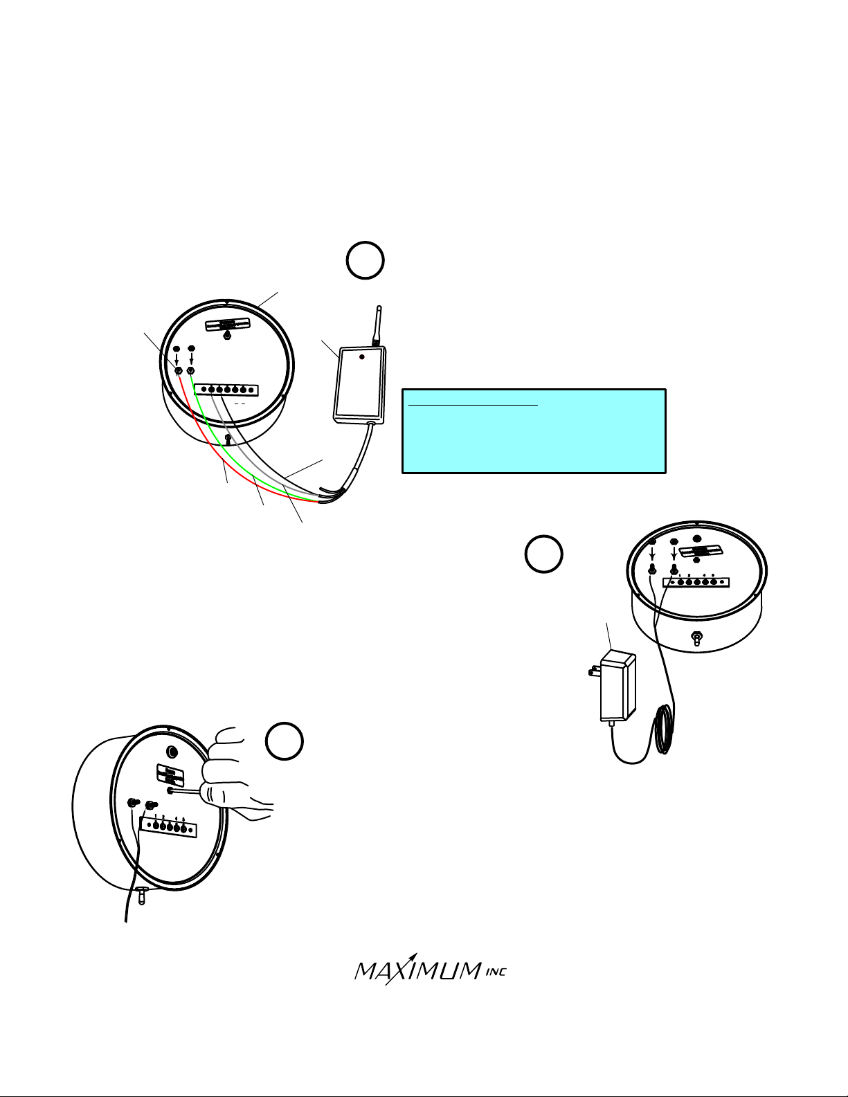
Wire the receiver to the Mystic display unit. Connect the
GREEN
and wires from the RECEIVER to the power terminals on
GREEN
the back of the MYSTIC (the polarity does not matter). Connect
WHITE
POWER
TERMINALS
RECEIVER
the wire from the RECEIVER to TERMINAL #1 and the
WHITE
BLACK wire from the RECEIVER to TERMINAL #2 on the rear
of the MYSTIC indicator.
1
2
3
4
IN
C
OM
OUT
RED
RED
5
GREEN
GREEN
BLACK
BLACK
WHITE
WHITE
RECEIVER WIRING
WHITE.............to...............TERMINAL #1
WHITE
BLACK
BLACK............to...............TERMINAL #2
.................to........Power (no polarity)
RED
RED
GREEN
GREEN
............to........Power (no polarity)
2
Connect the AC adapter to Mystic and plug into outlet. The display will
briefly light up all the indicator lights (self test). Next the display will show
the unit of measurement codes, the barometer function light will illuminate
and the center display will show a pressure reading. Leave Mystic in this
mode for two hours. Do not activate the switch at the bottom of the
case. At the end of this two hour period, Mystic will be ready to have the
pressure adjustment performed.
12 VOLT
POWER
SUPPLY
RED
RED
3
Now calibrate the barometer for your altitude. Obtain the current barometric
pressure for your area by calling a near-by airport or an individual who has a
properly set barometer. Insert a small screw driver into the recessed slotted
screw at the back of Mystic. Turn the screw while observing the pressure reading on the front of Mystic. Due to the sensitivity of this adjustment, the numbers
on the display may fluctuate during this procedure. It may take a minute to
achieve the exact setting. Once the unit is set, move the toggle switch to the
right (auto) one time to lock in the setting.
30 Barnet Boulevard
New Bedford, MA 02745
(508) 995-2200
Page 1
Page 2
MYSTIC
WIRELESS
INSTALLATION
4
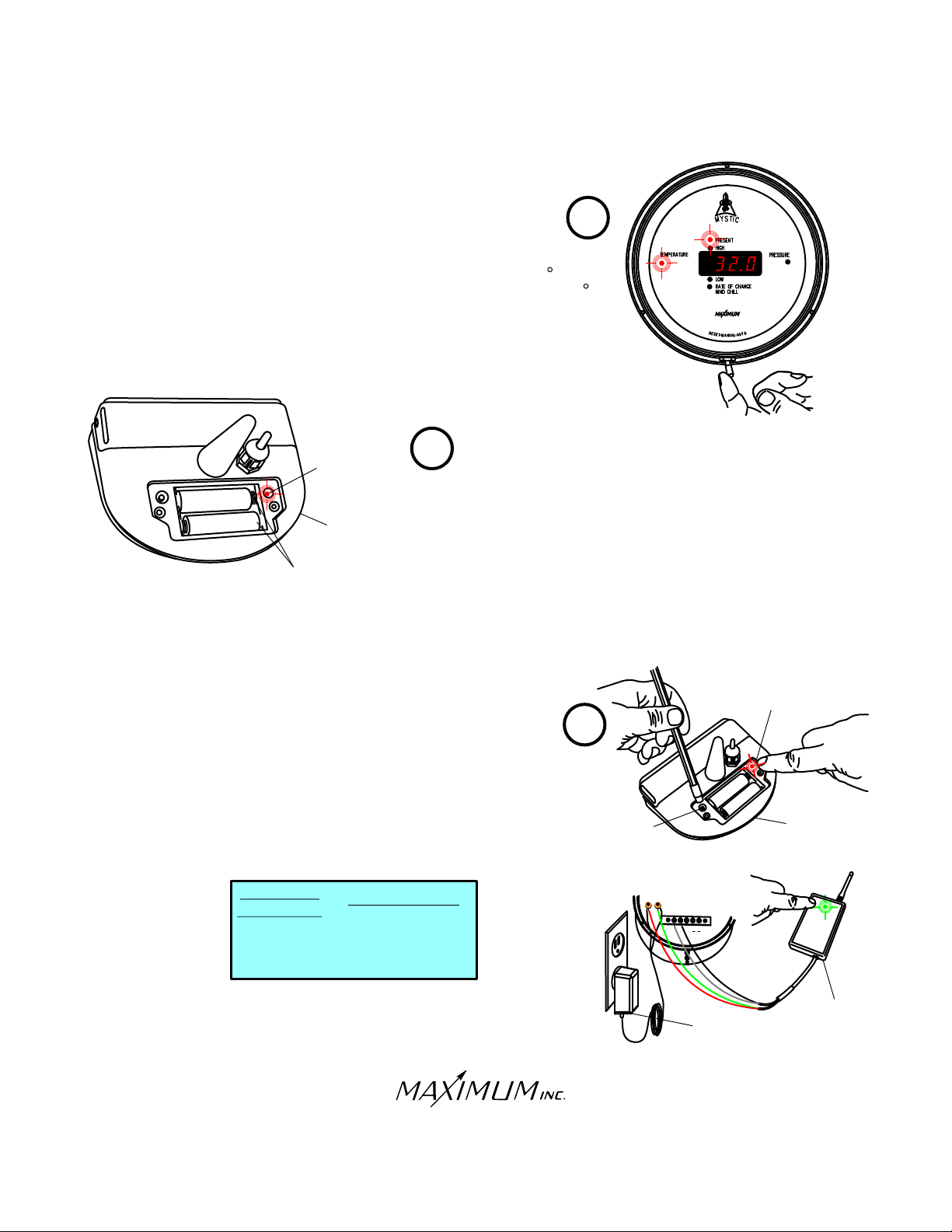
Once the barometer has been calibrated, toggle to a Present/Temperature
display. Within a few seconds a default temperature reading of 32.0 will
appear in the display window. Refer to the troubleshooting section if 32.0
does not appear.
5
Open the battery compartment of the temperature transmitter
by removing the stainless steel screws in the cover. Insert
two Alkaline batteries. The test light in the wireless transmitter
will blink red once to indicate that the batteries have been
installed properly.
A
I EA K
N
K
L
TEST LIGHT
L A
L
E
IN
AL
WIRELESS
TRANSMITTER
ALKALINE
BATTERIES
Test the transmitter by depressing the test button. After a few seconds
the test light should blink every four seconds. This indicates that the
transmitter is in test mode, which lasts for 15 minutes. At the end of
15 minutes the transmitter will return to normal operating mode. After
initial power up, the indicator light on the receiver should blink GREEN
GREEN
every four seconds. This indicates proper communication between the
receiver and the temperature transmitter.
(NOTE: If more than 15 minutes has passed since the button on the
temperature transmitter was pushed, it will need to be pushed again.)
The light on the receiver will blink other colors when different sensors
are installed.
RECEIVER
INDICATOR
RED
....................WIND
RED
GREEN
GREEN
ORANGE
ORANGE
.........TEMPERATURE
TRANSMITTER
................RAIN
6
TEST
BUTTON
TEST LIGHT
AL
K
ALIN
E
N
I
E
L
A
K
L
A
TRANSMITTER
1
2
3
4
5
IN
GND
O
UT
30 Barnet Boulevard
New Bedford, MA 02745
(508) 995-2200
Page 2
12 VOLT
RECEIVER
POWER SUPPLY
Page 3
MYSTIC
WIRELESS
INSTALLATION
7
8
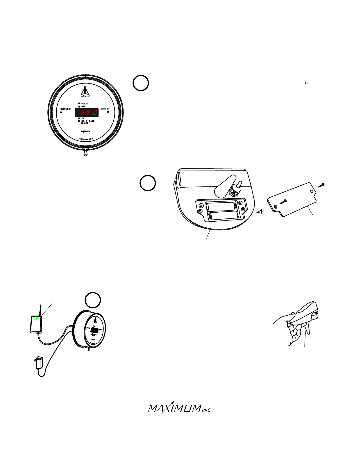
Replace the plastic battery cover. Make
sure to seat the cover properly over the
glued in gasket.
Once the transmitter has been activated, the default 32.0
temperature reading should be replaced by a present temperature
reading. Refer to the troubleshooting section if a present
temperature reading does not appear.
A
L N
I
EALK
E
A IN
K
L L
A
TEMPERATURE
SENSOR
COVER
RECEIVER
9
Move the active temperature transmitter as close as possible to
your preferred final mounting location. Also move the MYSTIC
indicator and receiver combination as close as possible to their
final mounting location. Select a location for the transmitter that
is protected from direct sunlight and sheltered from rain or
physical damage. A North exposure, six feet above the ground
will give the best results. Check to make sure that proper
communication between the transmitter and receiver still exists
by verifying that the light on the receiver is still flashing GREEN
every four seconds. NOTE: If more than 15 minutes has passed
since the test button on the temperature transmitter was pushed,
it will need to be pushed again. If the signal has been lost, move
the transmitter to an alternate mounting location and re-check
for proper communication.
30 Barnet Boulevard
New Bedford, MA 02745
(508) 995-2200
Page 3
GREEN
TRANSMITTER
Page 4
MYSTIC
WIRELESS
INSTALLATION
MOUNTING
SCREWS
BRACKET
10
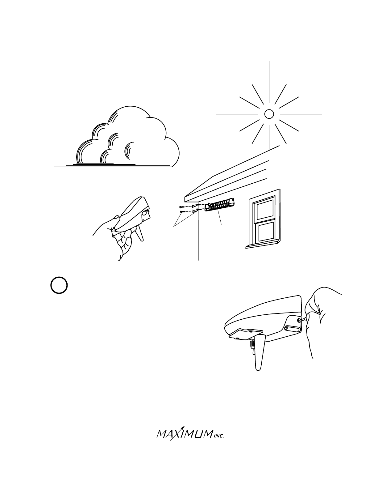
Once proper communication between the transmitter and receiver
is verified, final installation of the transmitter can be made.
Remove the four screws on the sides of the mounting bracket
and remove the bracket from the transmitter housing. Attach
the mounting bracket to the wall using the four stainless steel
mounting screws supplied in the hardware package. Once the
bracket is installed simply re-attach the transmitter housing to the
bracket using the four screws initially removed to separate the bracket
from the housing.
30 Barnet Boulevard
New Bedford, MA 02745
(508) 995-2200
Page 4
Page 5
MYSTIC
WIRELESS
INSTALLATION
HOLE
LLA
W
RECEIVER
12 VOLT
POWER
SUPPLY
SCREW
CABLE-HOLE
CABLES
SCREW
WOOD
PANEL
11
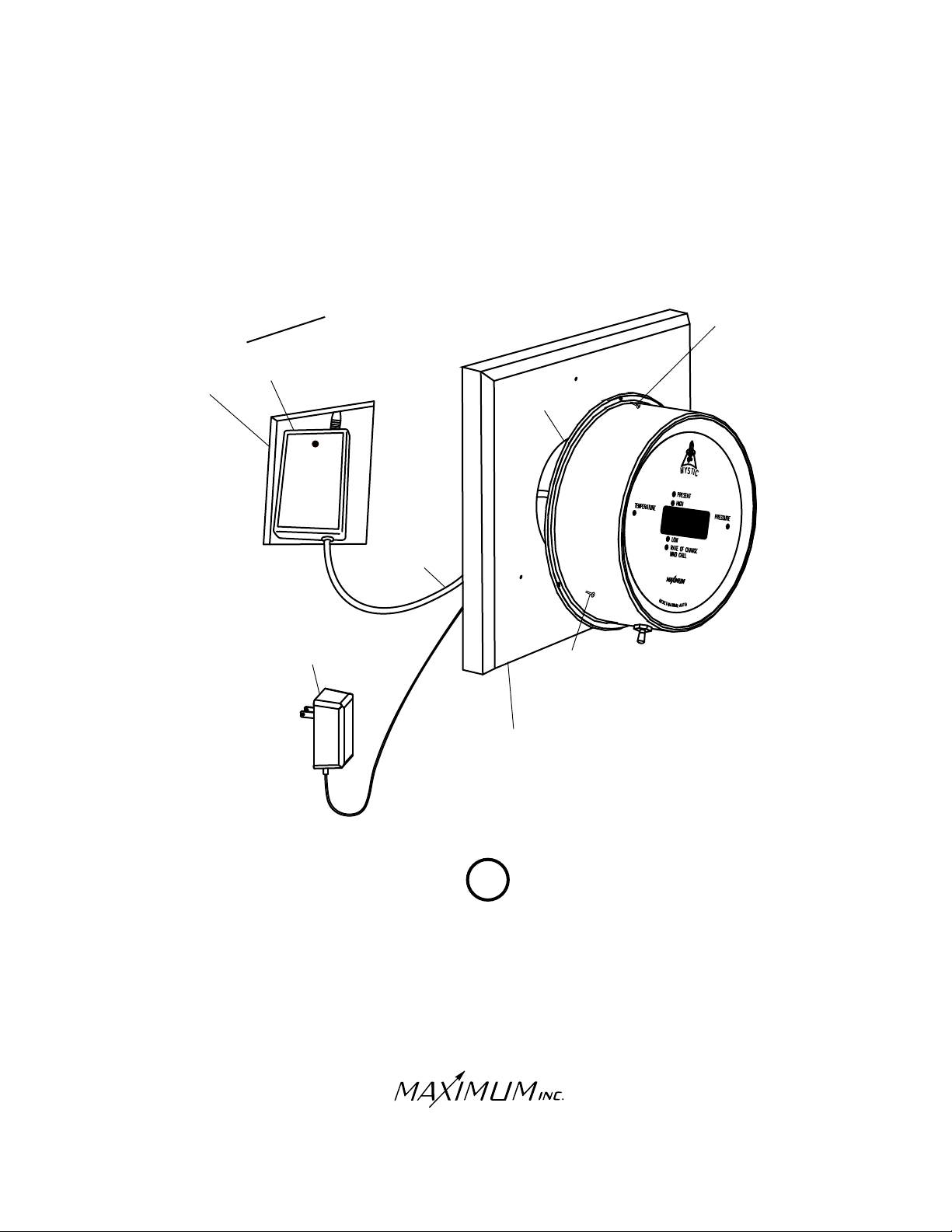
Mount the MYSTIC indicator directly over the cable hole that is also used
to route power to the instrument. For the cleanest installation, we recommend
making a hole in the wall large enough to insert the wireless receiver. We also
recommend mounting the brass meter to one of our pre-drilled mounting panels.
30 Barnet Boulevard
New Bedford, MA 02745
(508) 995-2200
Page 5
Page 6
MYSTIC
WIRELESS
OPERATION
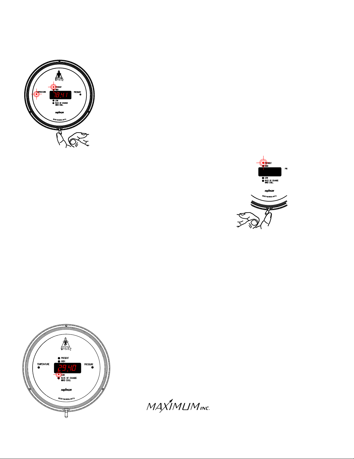
Move the toggle switch at the bottom of the case to the right (auto) and allow it
to return. This manually moves the Mystic through the individual functions. The
illuminated function LED’s indicate which function and setting is being displayed.
Moving the toggle switch to the right (auto) and holding it for at least three
seconds will put Mystic into its Auto sequencing mode. You will see each
function light stay on and that particular information displayed for approximately
four seconds and then move to the next function automatically.
If Mystic is Auto sequencing and you wish to turn that function off - move the
toggle switch to the right (auto) and release it. You can now manually
step through the functions as previously mentioned.
Any Individual function's memory can be independently reset. Move
the toggle switch to the right (auto) until that particular function is displayed.
Then move the toggle switch to the left (reset) and hold it for six seconds.
The display will quickly blank, indicating that the memory for that function
has been reset.
A "FULL" reset may also be done to clear all the memories simultaneously
or if an adjustment to the barometer setting is needed. Toggle through Mystic’s
settings until either the Present/Temperature or Present/Barometer function is displayed. Then move the toggle
switch to the left (reset) and hold it for six seconds. All the memories will reset, the display will quickly blank and
then enter into the barometer adjustment mode. If necessary the barometer may be reset at this time by adjusting
the set screw on the backplate. Exit the barometer adjustment mode by moving the toggle switch to the right
(auto) and releasing it.
NOTE: After any "FULL" reset, temperature and/or wind chill data will be displayed and
stored after ten seconds. Pressure data will be displayed and stored after two minutes.
However, Rate of Change/Pressure will show "HOLD" for 72 minutes following a
"FULL" reset.
When the toggle switch is in the center position Mystic will display the
information that is indicated by the function light. Data for all the other
functions is being recorded and stored.
30 Barnet Boulevard
New Bedford, MA 02745
(508) 995-2200
Page 6
Page 7
.
MYSTIC
WIRELESS
OPERATION (CONTINUED)
Mystic can be set to display the temperature in Fahrenheit or Celsius.
The barometric pressure can be set to inches of mercury, millimeters
of mercury, millibars or kilopascals. To change the units of measurement
follow these steps:
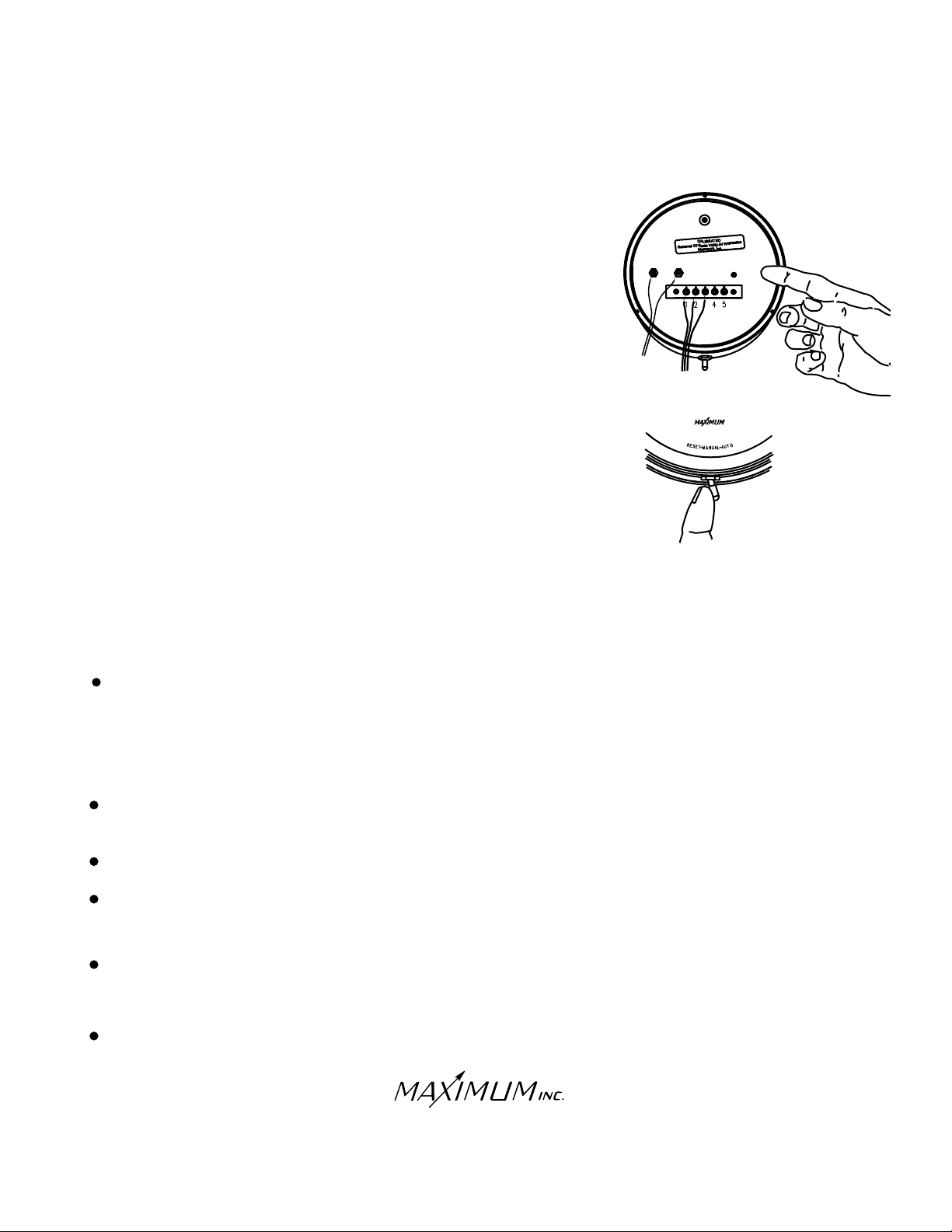
1. Press the small red push button switch on the back of the indicator
The display will show "F" or "C" (F=Fahrenheit, C=Celsius).
2. Press the red push button again to advance through the available temperature
units until the code you want is showing.
3. Move the toggle switch to the right (auto position) to lock in your choice.
4. The display will now show "P” and a number. The number indicates
the units of measurement for pressure.
P0 = inches of mercury
P1 = millimeters of mercury
P2 = millibars
P3 = kilopascals
5. Press the red push button again to advance through the available pressure units
until the code you want is showing.
6. Move the toggle switch to the right (auto position) to lock in your choice. Mystic
will now perform a self-test and return to normal operation.
IN GND OUT
3
IMPORTANT FACTS ABOUT YOUR MYSTIC
Latch Up- Power Line disturbances, improper powering up or an error in wiring can cause a blank or
improper display reading. If MYSTIC is "latched up" in this way proceed as follows:
1. Unplug the AC adapter from the 110 VAC power outlet.
2. Wait 15 seconds.
3. Plug the AC adapter in to the 110 VAC power outlet.
During power outages MYSTIC's display will blank out and the instrument will not continue to
accumulate data. It will preserve the previously accumulated data for up to 10 years.
Moving the switch to "Auto" does not erase stored information.
You do not need to time the 6 second reset time. Mystic will blank out the display to indicate that the
memory has been erased.
Set barometer by obtaining an accurate reading from a source as close to your location as possible.
The closest airport, weather bureau or an individual with an accurate barometer would be a few
examples.
Rate-of-Change indicates the measure of the rise or fall of the barometric pressure observed over a
one hour period. It is updated every 12 minutes.
.
30 Barnet Boulevard
New Bedford, MA 02745
(508) 995-2200
Page 7
Page 8
MYSTIC
WIRELESS
OPTIONAL INSTALLATION
MYSTIC WITH MERLIN
MERLIN
2
3
1
4
N
I
O
OUT
C M
12 VOLT
POWER
SUPPLY
WHITE
WHITE
5
BLACK
BLACK
MYSTIC
2
3
1
4
MO
N
I
OUT
C
5
WHITE
WHITE
BLACK
BLACK
RECEIVER
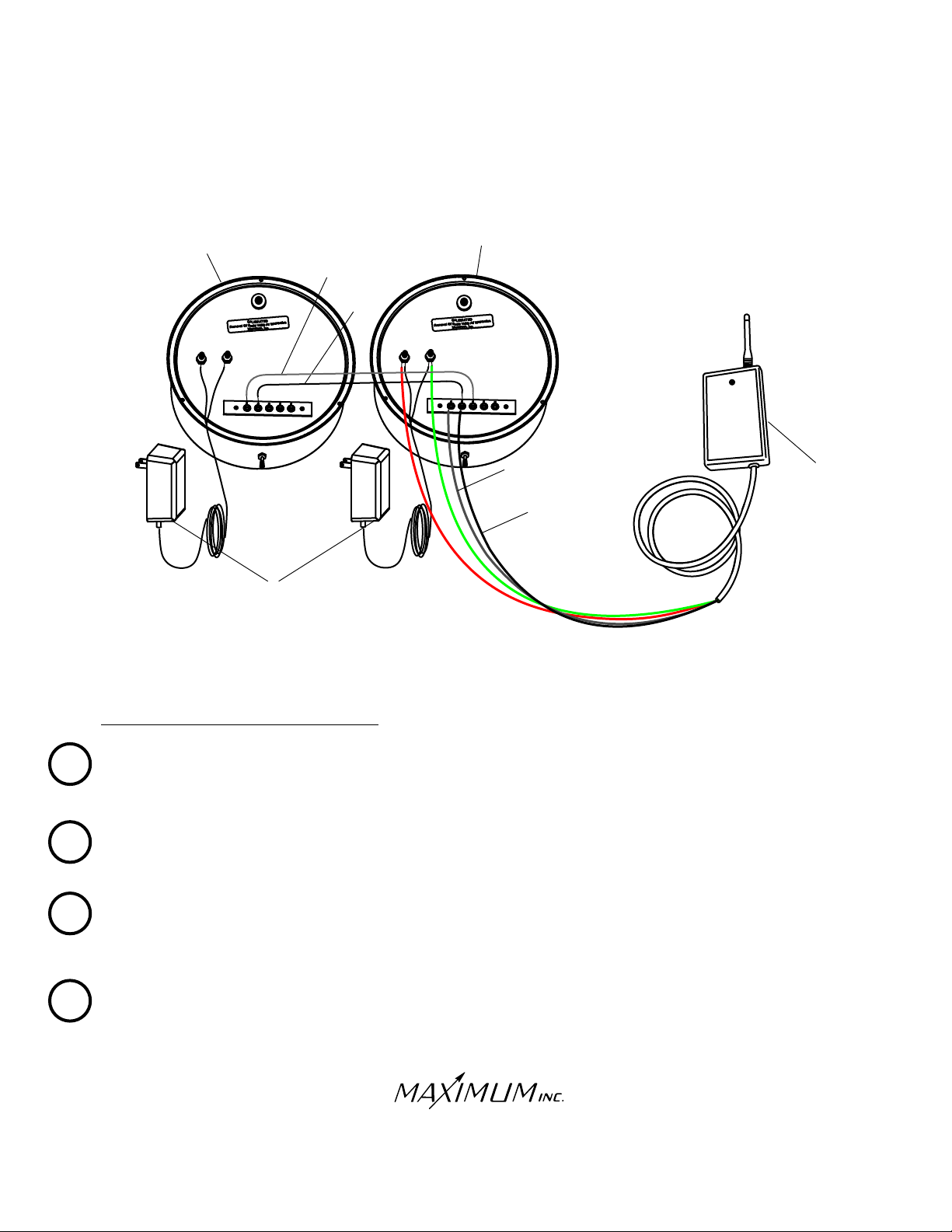
MYSTIC AND MERLIN CONNECTIONS
Connect the and wires from the RECEIVER to the power terminals on the back of the MYSTIC
1
(no polarity).
RED GREEN
RED
GREEN
Connect the wires from the 12 VOLT POWER SUPPLY to the same MYSTIC power terminals (no polarity).
On the MYSTIC, connect the wire from the RECEIVER to TERMINAL #1 (IN) and the BLACK wire from
2
the RECEIVER to TERMINAL #2 (COM).
Connect the two instruments using the supplied grey sheathed BLACK and wires as follows:
3
A. Connect the wire from MERLIN TERMINAL #1 (IN) to MYSTIC TERMINAL #3 (OUT)
B. Connect the BLACK wire from MERLIN TERMINAL #2 (COM) to MYSTIC TERMINAL #2 (COM)
4
Connect the wires from the 12 VOLT POWER SUPPLY to the MERLIN power terminals (no polarity).
WHITE
WHITE
BLACK
WHITE
WHITE
BLACK
WHITE
WHITE
BLACK
30 Barnet Boulevard
New Bedford, MA 02745
(508) 995-2200
Page 8
Page 9
MYSTIC
WIRELESS
OPTIONAL INSTALLATION
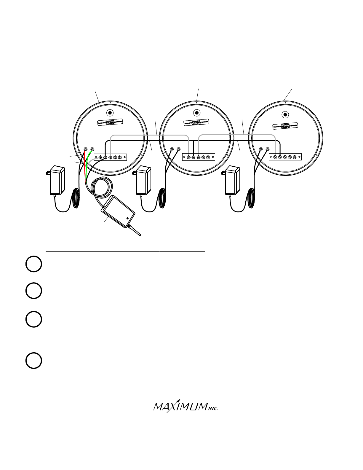
MYSTIC WITH MERLIN AND RAINWATCH
MERLIN
1 2 3 4
IN
OUT
COM
RED
RED
GREEN
GREEN
MYSTIC
AC ADAPTER
1 2 3 4
IN
COM
WHITE
WHITE
AC ADAPTER
BLACK
5
OUT
RECEIVER
RAINWATCH WITH MERLIN AND MYSTIC CONNECTIONS
RAINWATCH
WHITE
WHITE
AC ADAPTER
BLACK
5
1 2 3 4
5
IN
OUT
COM
Connect the and wires from the RECEIVER to the power terminals on the back of the MYSTIC
1
(no polarity).
RED GREEN
RED
GREEN
Connect the wires from the 12 VOLT POWER SUPPLY to the same MYSTIC power terminals (no polarity).
On the MYSTIC, connect the wire from the RECEIVER to TERMINAL #1 (IN) and the BLACK wire
2
from the RECEIVER to TERMINAL #2 (COM).
Connect the MYSTIC and MERLIN instruments using the supplied grey sheathed BLACK and wires
3
as follows:
A. Connect the wire from MERLIN TERMINAL #1 (IN) to MYSTIC TERMINAL #3 (OUT).
WHITE
WHITE
WHITE
WHITE
WHITE
WHITE
B. Connect the BLACK wire from MERLIN TERMINAL #2 (COM) to MYSTIC TERMINAL #2 (COM).
Connect the MERLIN and RAINWATCH instruments using the supplied grey sheathed BLACK and WHITE
4
wires as follows:
A. Connect the WHITE wire from RAINWATCH TERMINAL #1(IN) to MERLIN TERMINAL #3 (OUT)
WHITE
B. Connect the BLACK wire from RAINWATCH TERMINAL #2(COM) to MERLIN TERMINAL #2(COM).
30 Barnet Boulevard
New Bedford, MA 02745
(508) 995-2200
Page 9
WHITE
Page 10
WIRELESS
TROUBLE-SHOOTING
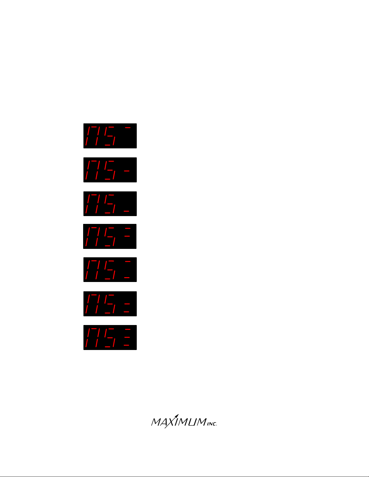
Occasionally, you may experience disruptions in data transmission. The most likely cause will be expired batteries
in the Exterior Sensor/Transmitters. When the following error codes appear in the LED readout, the batteries will
most likely need replacing (please note the location of the horizontal dash lines):
Wind sensor not transmitting
Temperature sensor not transmitting
Rain sensor not transmitting
Wind and Temperature sensor not transmitting
Wind and Rain sensor not transmitting
Temperature and Rain sensor not transmitting
Wind, Temperature and Rain sensor not transmitting
NS=No Signal
The following pages of this manual contain more detailed information regarding
the specific error displays.
30 Barnet Boulevard
New Bedford, MA 02745
(508) 995-2200
Page 10
Page 11
WIRELESS
TROUBLE-SHOOTING
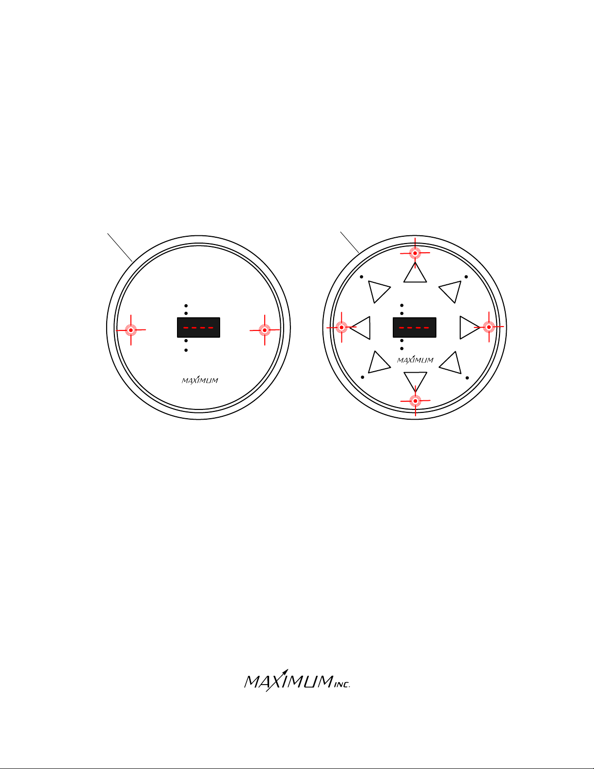
THE FOLLOWING ILLUSTRATIONS SHOW HOW THE INSTRUMENT
DIAL WILL INDICATE IMPROPER OPERATION.
NO SERIAL DATA
(Instrument has never recognized a receiver)
MYSTIC
TEMPERATURE
MERLIN
MYSTIC
W
PRESENT
HIGH
LOW
RATE OF CHANGE
WIND CHILL
PRESSURE
SYMPTOM:
-Center (Numeric) LED’s display “- - - -”.
-Mystic Temperature and Pressure LED’s are illuminated.
-Merlin Primary Wind Direction LED’s are illuminated.
N
W
W
N
N
MERLIN
PRESENT
PEAK
E
E
AVERAGE
FORECAST
S
S
E
S
REMEDY:
-Check all wire connections (Refer to installation diagrams)
-Re-boot the system by unplugging the power supply,
wait 30 seconds, plug it back in.
-The light on the receiver will flash RED and then
GREEN
GREEN five times, indicating that the receiver is
RED
now powered-up.
-If the instrument continues to display the error code,
call Maximum for further assistance.
Note: Depending on the origin of the problem, error
codes may not display on all instruments.
30 Barnet Boulevard
New Bedford, MA 02745
(508) 995-2200
Page 11
Page 12
WIRELESS
TROUBLE-SHOOTING
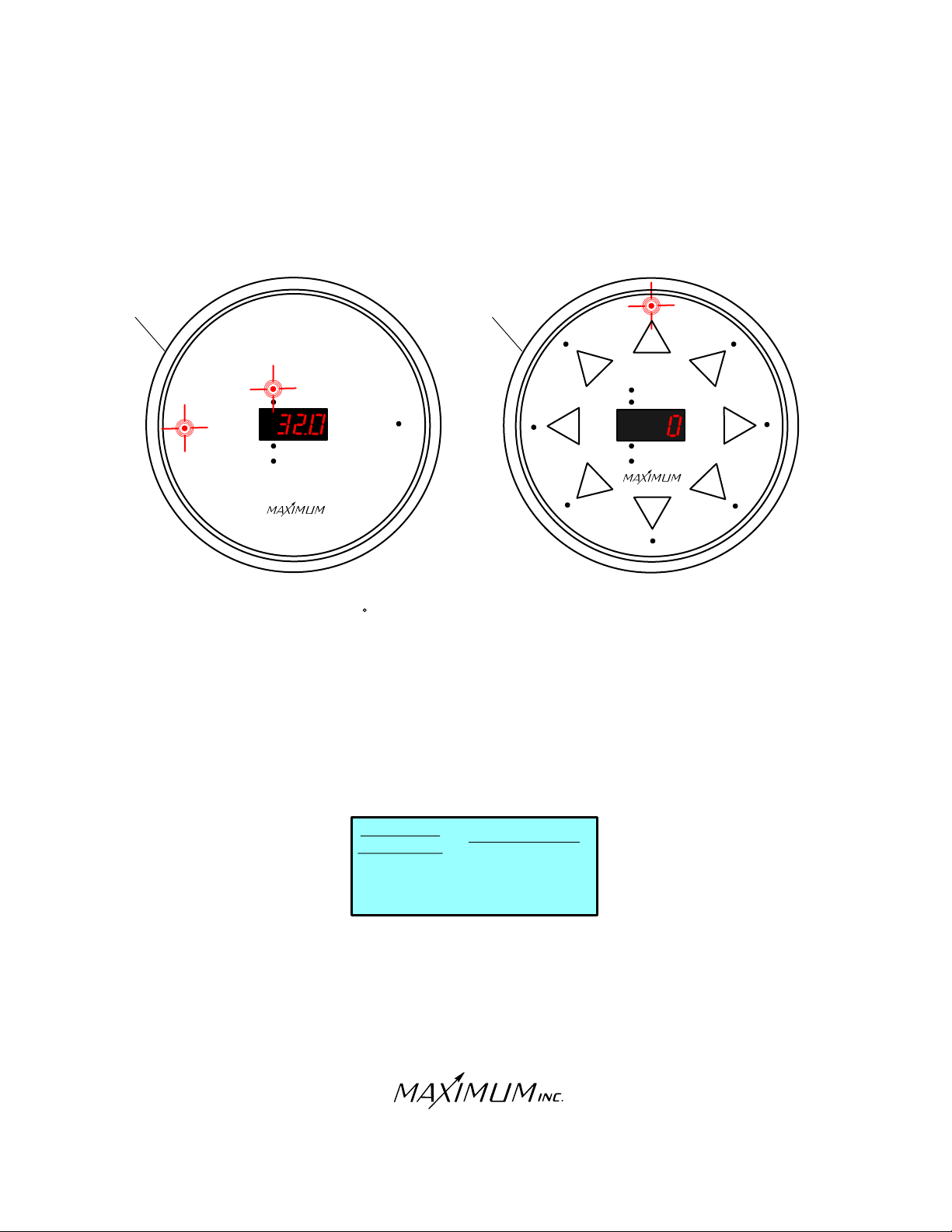
NO SIGNAL FROM ANY TRANSMITTER
(Instrument recognizes the receiver, but the receiver does not recognize the sensor(s))
MYSTIC
TEMPERATURE
MERLIN
MYSTIC
PRESENT
HIGH
PRESSURE
NW
W
LOW
RATE OF CHANGE
WIND CHILL
W
S
SYMPTOM:
-Mystic reads 32 F and the Temperature and Present LED’s are
illuminated.
-Merlin reads 0 mph and the North direction LED is illuminated.
REMEDY:
-Test the batteries in each external SENSOR/TRANSMITTER
and replace if necessary.
-Put the TRANSMITTER(S) into TEST MODE by pressing TEST
BUTTON in the battery compartment of TRANSMITTER.
-Remove the RECEIVER from the wall and confirm receipt of
TRANSMISSION(S) based on the color of the flashing light.
N
MERLIN
PRESENT
PEAK
AVERAGE
FORECAST
S
NE
E
S
E
RECEIVER
INDICATOR
RED
....................WIND
RED
GREEN
ORANGE
ORANGE
.........TEMPERATURE
GREEN
TRANSMITTER
................RAIN
-If the instrument continues to display the error code, call Maximum
for further assistance.
Note: Depending on the origin of the problem, error
codes may not display on all instruments.
30 Barnet Boulevard
New Bedford, MA 02745
(508) 995-2200
Page 12
Page 13
WIRELESS
TROUBLE-SHOOTING
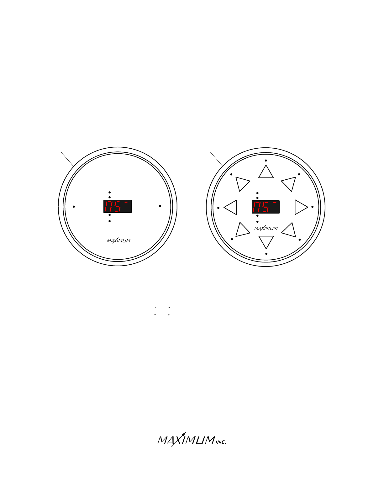
NO SIGNAL FROM WIND TRANSMITTER
(Instrument has received, then lost sensor signal)
MYSTIC
TEMPERATURE
MERLIN
MYSTIC
N
W
MERLIN
PRESENT
HIGH
PRESSURE
N
PRESENT
PEAK
W
LOW
RATE OF CHANGE
WIND CHILL
AVERAGE
FORECAST
WS
S
SYMPTOM:
-Mystic Reads NS (No Temperature or Pressure LED’s illuminated).
-Merlin Reads NS (No Direction LED’s illuminated).
NE
E
S
E
REMEDY:
-Re-charge and/or replace the AA NiCad batteries in the WIND
TRANSMITTER.
-Put TRANSMITTER into TEST MODE by pressing the TEST BUTTON
in the battery compartment of TRANSMITTER. This should cause the
LED on the receiver to flash RED every 2 seconds.
RED
-If the instrument continues to display the error code, call Maximum
for further assistance.
30 Barnet Boulevard
New Bedford, MA 02745
(508) 995-2200
Page 13
Page 14
WIRELESS
TROUBLE-SHOOTING
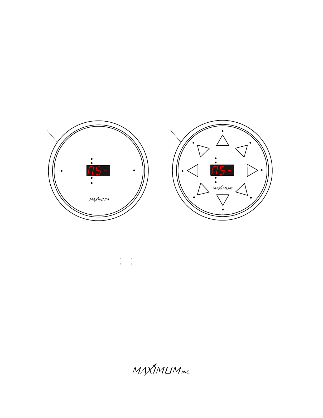
NO SIGNAL FROM TEMPERATURE TRANSMITTER
(Instrument has received, then lost sensor signal)
MYSTIC
TEMPERATURE
MERLIN
MYSTIC
MERLIN
PRESENT
HIGH
PRESSURE
NW
W
LOW
RATE OF CHANGE
WIND CHILL
SYMPTOM:
-Mystic Reads NS (No Temperature or Pressure LED’s illuminated).
-Merlin Reads NS (No Direction LED’s illuminated).
PRESENT
PEAK
AVERAGE
FORECAST
W
S
N
NE
E
SE
S
REMEDY:
-Test and replace (if necessary) the AA Alkaline batteries in the
TEMPERATURE TRANSMITTER.
-Put TRANSMITTER into TEST MODE by pressing the TEST BUTTON
in the battery compartment of the TRANSMITTER. This should cause the
LED on the receiver to flash GREEN every 4 seconds.
GREEN
-If the instrument continues to display the error code, call Maximum
for further assistance.
30 Barnet Boulevard
New Bedford, MA 02745
(508) 995-2200
Page 14
Page 15
WIRELESS
TROUBLE-SHOOTING
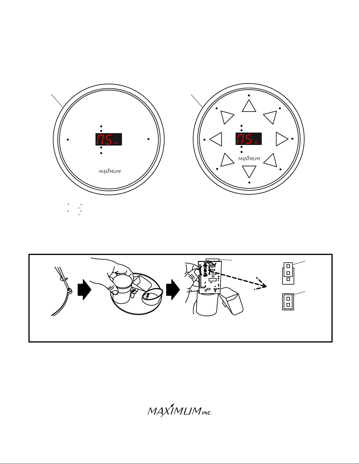
NO SIGNAL FROM RAIN TRANSMITTER
(Instrument has received, then lost sensor signal)
MYSTIC
MYSTIC
MERLIN
N
NE
E
S
E
TEMPERATURE
PRESENT
HIGH
LOW
RATE OF CHANGE
WIND CHILL
PRESSURE
W
W
MERLIN
N
PRESENT
PEAK
AVERAGE
FORECAST
W
S
S
SYMPTOM:
-Mystic Reads NS (No Temperature or Pressure LED’s illuminated).
-Merlin Reads NS (No Direction LED’s illuminated).
REMEDY:
-Test and replace (if necessary) the AA Alkaline batteries in the RAIN TRANSMITTER.
-Put the RAIN TRANSMITTER into TEST MODE by removing the batteries, then moving the jumper on the
RAIN TRANSMITTER circuit board to cover both pins of the 2-pin terminal.
BATTERY
JUMPER
COMPARTMENT
OPERATING
MODE
JUMPER
TEST
MODE
REMOVE OUTER
CASE BY LOOSENING
FOUR SCREWS
SLIP CAP OFF
CYLINDER HOUSING
TRANSMITTER
CIRCUIT BOARD
REMOVE
TRANSMITTER
CIRCUIT BOARD
FROM CYLINDER
SET JUMPER TO
TEST MODE BY
COVERING BOTH PINS
-Re-install the AA Alkaline batteries in the RAIN TRANSMITTER once the jumper has been moved.
-Check LED on receiver to make sure it is blinking ORANGE every 4 seconds.
ORANGE
-Check the instruments to see if the error has been corrected.
-Unlike the WIND and TEMPERATURE TRANSMITTERS, the RAIN TRANSMITTER will not automatically
exit test MODE after 15 minutes. Therefore, you must take the rain transmitter out of test mode manually. To
do so: remove the batteries, then move the jumper on the RAIN TRANSMITTER circuit board back to covering
only one pin of the 2-pin terminal (it does not matter which pin is covered). Re-install the batteries and cover.
-If the instrument continues to display the error code, call Maximum for further assistance.
30 Barnet Boulevard
New Bedford, MA 02745
(508) 995-2200
Page 15
Page 16
WIRELESS
FCC NOTICE
Warning: Changes or modifications to this equipment not expressly approved by Maximum,
Inc. in writing as the party responsible for compliance could void the user’s authority to
operate the equipment.
NOTE: This equipment has been tested and found to comply with the limits for a CLASS B
Digital Device, pursuant to Part 15 of the FCC Rules. These limits are designed to provide
reasonable protection against harmful interference in a residential installation. This equipment
generates, uses and can radiate radio frequency energy and, if not installed and used in
accordance with the instructions, may cause harmful interference to radio communications.
However, there is no guarantee that interference will not occur in a particular installation. If
this equipment does cause harmful interference to radio or television reception, which can
be determined by turning the equipment off and on, the user is encouraged to try to correct
the interference by one or more of the following measures:
Reorient or relocate the receiving antenna.
Increase the separation between the equipment and the receiver.
Connect the equipment into an outlet on a circuit different from that to which the
receiver is connected.
Consult the dealer or an experienced radio/TV technician for help.
NOTES
30 Barnet Boulevard
New Bedford, MA 02745
(508) 995-2200
Page 16
Page 17

R
W E A T H E R I N S T R U M E N T S
Electrical Damage - Common Causes & Recommended Prevention
Electrical damage can be caused by many different factors. Below are some of the more common causes and
some suggested methods of minimizing potential problems.
Common Causes:
Storm Activity - lightening in your area can do damage to your instruments in different ways. The obvious
way is due to a direct or nearby strike. In addition, lightening storms, dust storms, dry snowstorms and
strong dry winds can all cause static electricity to build up on and around your external sensors. Regardless
of the cause, this built up electricity itself through the cable connecting the external sensors to
the instrument.
Power Surges - A surge may come from the electric company’s switching generators or power grids, from
local industries or after power interruption when accumulated power suddenly surges back through AC lines.
Even the on-and-off switching of large electrical appliances, such as refrigerators or clothes dryers can
create damaging fluctuations. This is especially true with sensitive weather recording devices.
Yourself - Are you constantly giving and/or receiving a shock every time you touch a doorknob or other
person? If so, you have a great deal of static electricity in your environment. In either case, it is possible for a
person to carry enough of a charge to damage an instrument.
Recommended Prevention:
Use Surge Protectors - for the AC adapter, a UL 1449 rated surge protector with EMI/RFI filtering is
recommended. This rating will be clearly listed on the packaging of all good quality surge protector.
Discharge Yourself - If the instruments are located in an environment where static electricity is a problem,
make sure that you discharge yourself before touching the instrument(s). The shock that you get from
touching a doorknob or another person can often be sufficient to damage an instrument.
30 SAMUEL BARNET BOULEVARD NEW BEDFORD, MASSACHUSETTS 02745 U.S.A.
TEL. 508.995.2200 WWW.MAXIMUM-INC.COM FAX 800.989.2580
Page 17
 Loading...