

Page 1
MAESTRO
WIRELESS
INSTALLATION
THIS MANUAL IS DESIGNED TO LEAD YOU STEP BY STEP THROUGH THE PROCEDURES REQUIRED
TO TEST, INSTALL AND USE YOUR WIRELESS MAESTRO. BY FOLLOWING THESE PROCEDURES AND
SETTING UP THE SYSTEM CORRECTLY IN THE BEGINNING, YOU WILL BE ABLE TO ENJOY ALL THE
FEATURES OF YOUR WIRELESS MAESTRO FOR YEARS TO COME. WE STRONGLY SUGGEST THAT
YOU PERFORM A TRIAL WIRING OF YOUR WIRELESS MAESTRO PRIOR TO FINAL INSTALLATION.
Locate the NiCad Batteries and Battery charger, then charge the
batteries according to the charger instructions. You will need them
later. The NiCad batteries will be kept charged by the solar panel
when installed in the transmitter. They should not need replacement
for two to three years. When they do need replacement use 1000
milliamp/hour NiCad batteries. (Do NOT use Alkaline or NiMH
batteries.)
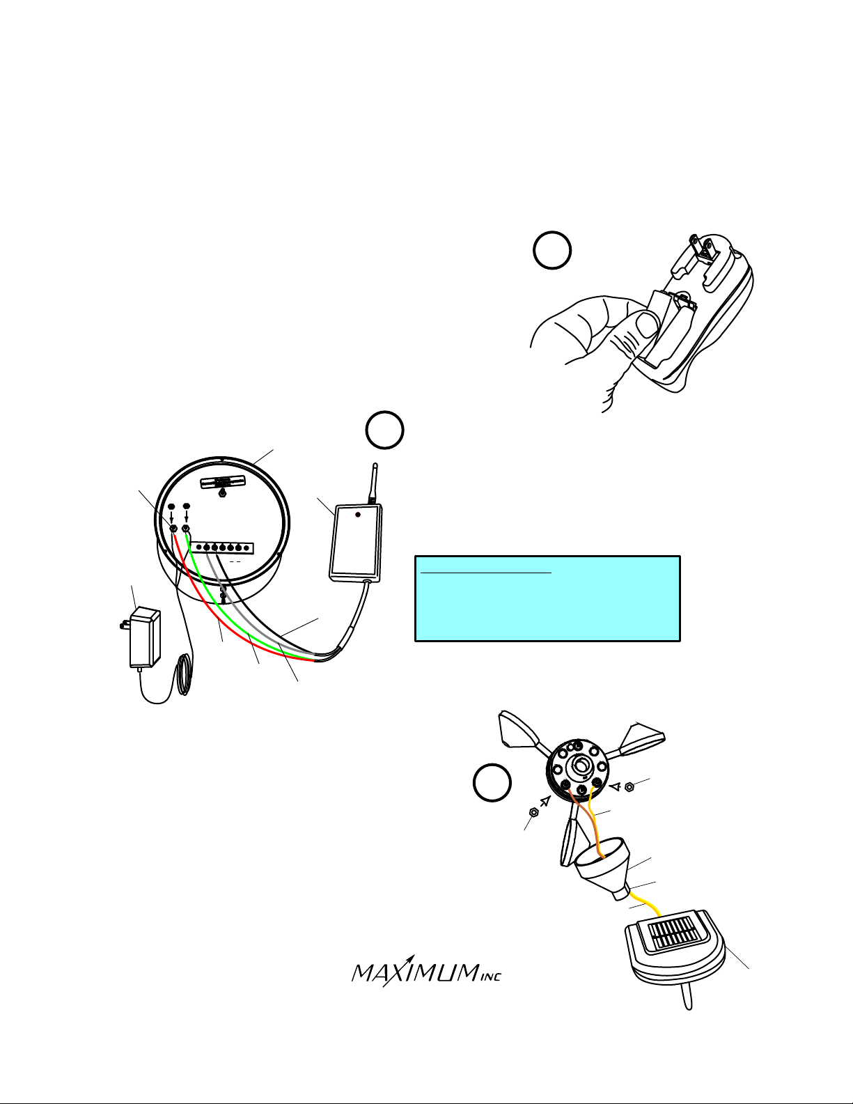
You now need to wire your receiver to your display unit.
MAESTRO
2
Connect the and wires from the RECEIVER
RED GREEN
RED
to the power terminals on the back of the MAESTRO (the
POWER
TERMINALS
RECEIVER
polarity does not matter). Connect the wires from the 12 volt
power supply to the same power terminals (again the polariity
does not matter). Connect the wire from the RECEIVER
to TERMINAL #1 and the BLACK wire from the RECEIVER to
TERMINAL #2 on the rear of the MAESTRO meter.
12 VOLT
POWER
SUPPLY
1
2
3
4
5
IN
G
N
D
O
U
T
RECEIVER WIRING
WHITE.............to...............TERMINAL #1
WHITE
BLACK............to...............TERMINAL #2
BLACK
RED
RED
GREEN
GREEN
BLACK
WHITE
WHITE
.................to........Power (no polarity)
RED
RED
GREEN
GREEN
............to........Power (no polarity)
1
GREEN
WHITE
WHITE
0
0
00
1
Feed the and wires from the Wireless
YELLOW BROWN
YELLOW
BROWN
Wind Transmitter through the small access hole in one of the
black rubber boots. Using the solid brass nuts from the
Hardware Pack, attach the wires to the two terminals on the
Wind Speed Sensor (no polarity). Do NOT adjust the nuts that
are already on the sensor.
30 Barnet Boulevard
New Bedford, MA 02745
(508) 995-2200
Page 1
3
BRASS
NUT
YELLOW
YELLOW BROWN
AND
WIRES
BRASS
NUT
YELLOW
YELLOW BROWN
WIRES
BOOT
SMALL HOLE
BROWN
BROWN
AND
IN BOOT
WIRELESS
TRANSMITTER
Page 2
MAESTRO
WIRELESS
INSTALLATION
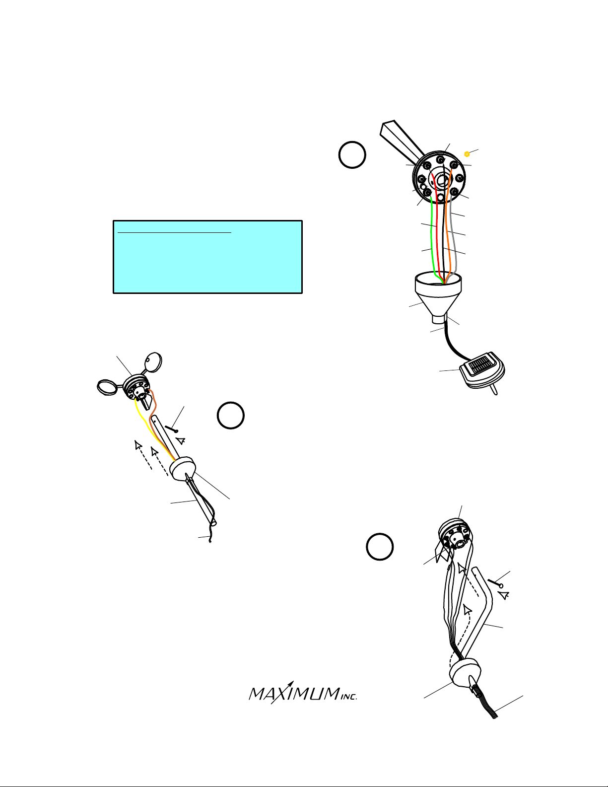
Feed the terminal lug end of the five-conductor cable
through the other rubber boot and connect the lugs to
the terminals on the bottom of the wind-direction sensor
with the brass nuts from the Hardware Pack. Do NOT
adjust the nuts that are already on the sensor.
TRANSMITTER WIRING
WHITE.............to...............TERMINAL #1
WHITE
ORANGE
ORANGE
BLACK............to...............TERMINAL #3
RED
RED
GREEN
GREEN
WIND SPEED
SENSOR
STRAIGHT
STUB MAST
.........to...............TERMINAL #2
.................to...............TERMINAL #4
............to...............TERMINAL #5
COTTER
PIN
5
BOOT
Slide the straight stub mast through the black rubber
boot and insert it into the Wind Speed Sensor, securing
it with the supplied stainless steel cotter pin. Once the
final installation is made and proper function is verified,
coat all the wire connections with a silicone sealant
designed for electrical connections (not supplied). Slip
the boot over the base of the sensor.
4
5-CONDUCTOR
TRANSMITTER
4
BOSS
RED
RED
GREEN
GREEN
BOOT
CABLE
WIRELESS
3
5
SMALL HOLE
WIND DIRECTION
SENSOR
BRASS
NUT
2
1
WHITE
WHITE
ORANGE
ORANGE
BLACK
IN BOOT
2-CONDUCTOR
CABLE
Slide the “Z” shaped mast through the black rubber boot and
insert it into the Wind Direction Sensor. Align the sensor so
that the number 3 terminal is located over the horizontal
section of the “Z” shaped mast and secure it with the supplied
stainless steel cotter pin. Once the final installation is made
and proper function is verified, coat all the wire connections
with a silicone sealant designed for electrical connections
(not supplied). Slip the boot over the base of the sensor.
Align the sensor so that the number 3 terminal is located
over the horizontal section of the “Z” shaped mast
30 Barnet Boulevard
New Bedford, MA 02745
(508) 995-2200
Page 2
6
TERMINAL
#3
ALIGNED
OVER
MAST
BOOT
COTTER
PIN
Z-STUB
MAST
5-CONDUCTOR
CABLE
Page 3
MAESTRO
WIRELESS
INSTALLATION
7
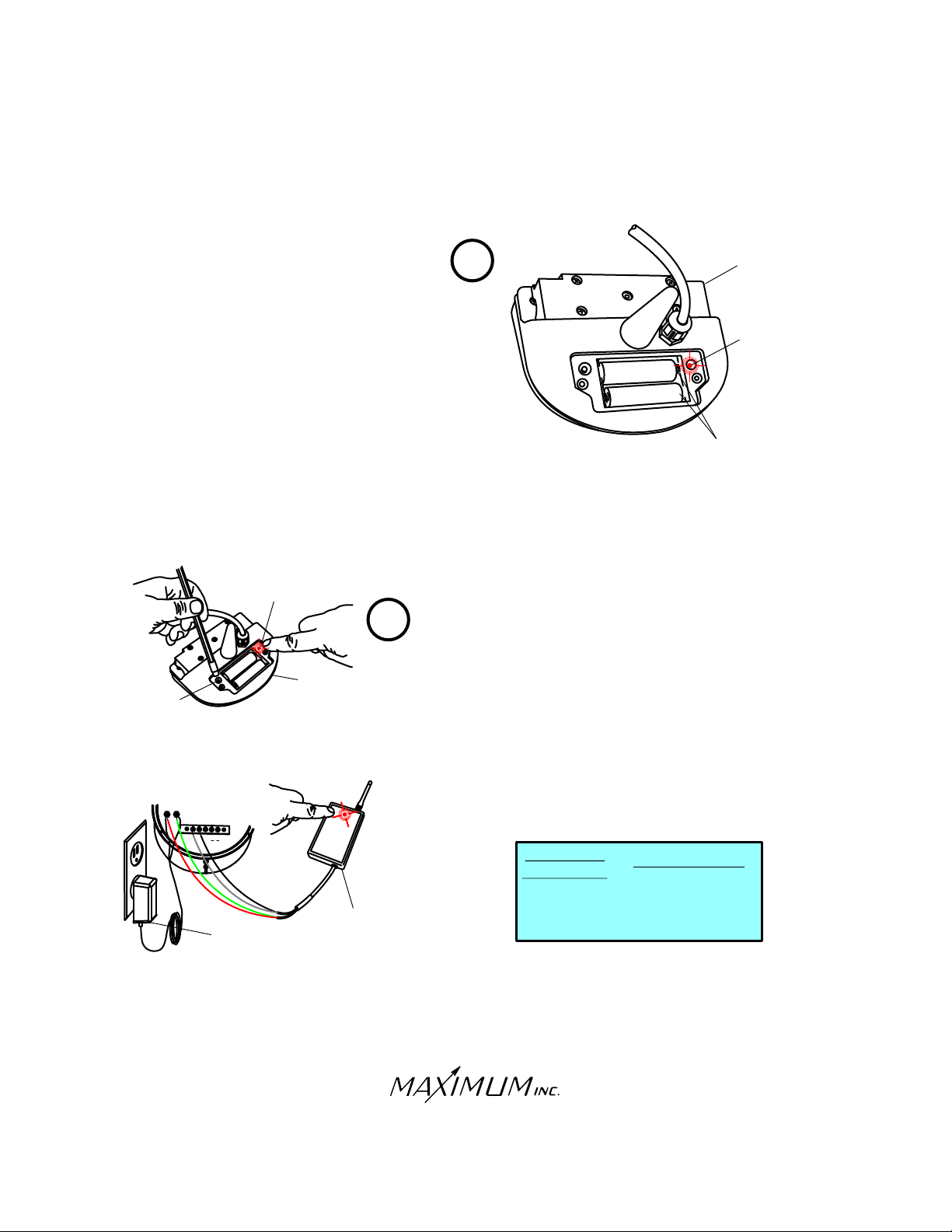
Open the battery compartment by removing the stainless
steel screws in the cover. Insert the two 1000 Milliamp
Ni-Cad batteries that have been fully charged per the
charger instructions. The test light in the wireless
transmitter will blink once to indicate that the batteries
have been installed properly.
0
0
01
000
1
1000 MILLIAMP
NI-CAD BATTERIES
WIRELESS
TRANSMITTER
TEST LIGHT
TEST
BUTTON
TEST LIGHT
1000
0
010
1
2
3
4
5
I
N
GND
O
UT
12 VOLT
POWER SUPPLY
8
TRANSMITTER
RECEIVER
Plug in the 12 volt power supply that is connected to the
instrument and the receiver Test the transmitter by depressing
.
the test button. After a few seconds the test light should blink
every two seconds. This indicates that the transmitter is in test
mode, which lasts for 15 minutes. At the end of 15 minutes the
transmitter will return to normal operating mode.
After initial
power up, the indicator light on the receiver should blink red
every two seconds. This indicates proper communication
between the receiver and the wind transmitter. (NOTE: If more
than 15 minutes has passed since the button on the wind
transmitter was pushed it will need to be pushed again.) The
light on the receiver will blink other colors when different sensors
are installed.
RECEIVER
INDICATOR
RED
....................WIND
RED
GREEN
GREEN
ORANGE
ORANGE
TRANSMITTER
.........TEMPERATURE
................RAIN
30 Barnet Boulevard
New Bedford, MA 02745
(508) 995-2200
Page 3
Page 4
MAESTRO
WIRELESS
INSTALLATION
9
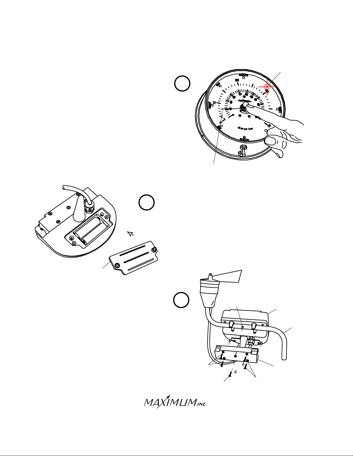
Perform a test of your wireless MAESTRO. Spin the cups on
the wind sensor and a speed should be indicated on the dial
(there will be a brief delay). Slowly rotate the vane on the wind
direction sensor and the lights indicating wind direction should
change (again, there will be a brief delay).
If the above tests do not produce the results described, refer
to the trouble-shooting section at the back of this manual for
assistance.
WIND
DIRECTION
LIGHTS
WIND SPEED
INDICATED
ON DIAL
10
Replace the plastic battery cover. Make
10
00
01
0 0
cover
Mount the Wireless Wind Transmitter to the “Z” shaped
arm. Remove the four stainless steel screws holding the
locking bracket. Place the transmitter over the arm as
shown. Insert one stainless steel screw through the
center of the locking bracket and into the alignment hole
in the z-shaped arm. Re-attach the locking bracket
with the four remaining stainless steel screws.
sure to seat the cover properly over the
glued in gasket.
11
STAINLESS-STEEL
MOUNTING SCREWS
STAINLESS-STEEL
ALIGNMENT SCREW
ALIGNMENT
HOLE
STAINLESS-STEEL
MOUNTING SCREWS
WIRELESS
TRANSMITTER
Z-SHAPED ARM
LOCKING
BRACKET
30 Barnet Boulevard
New Bedford, MA 02745
(508) 995-2200
Page 4
Page 5
MAESTRO
WIRELESS
INSTALLATION
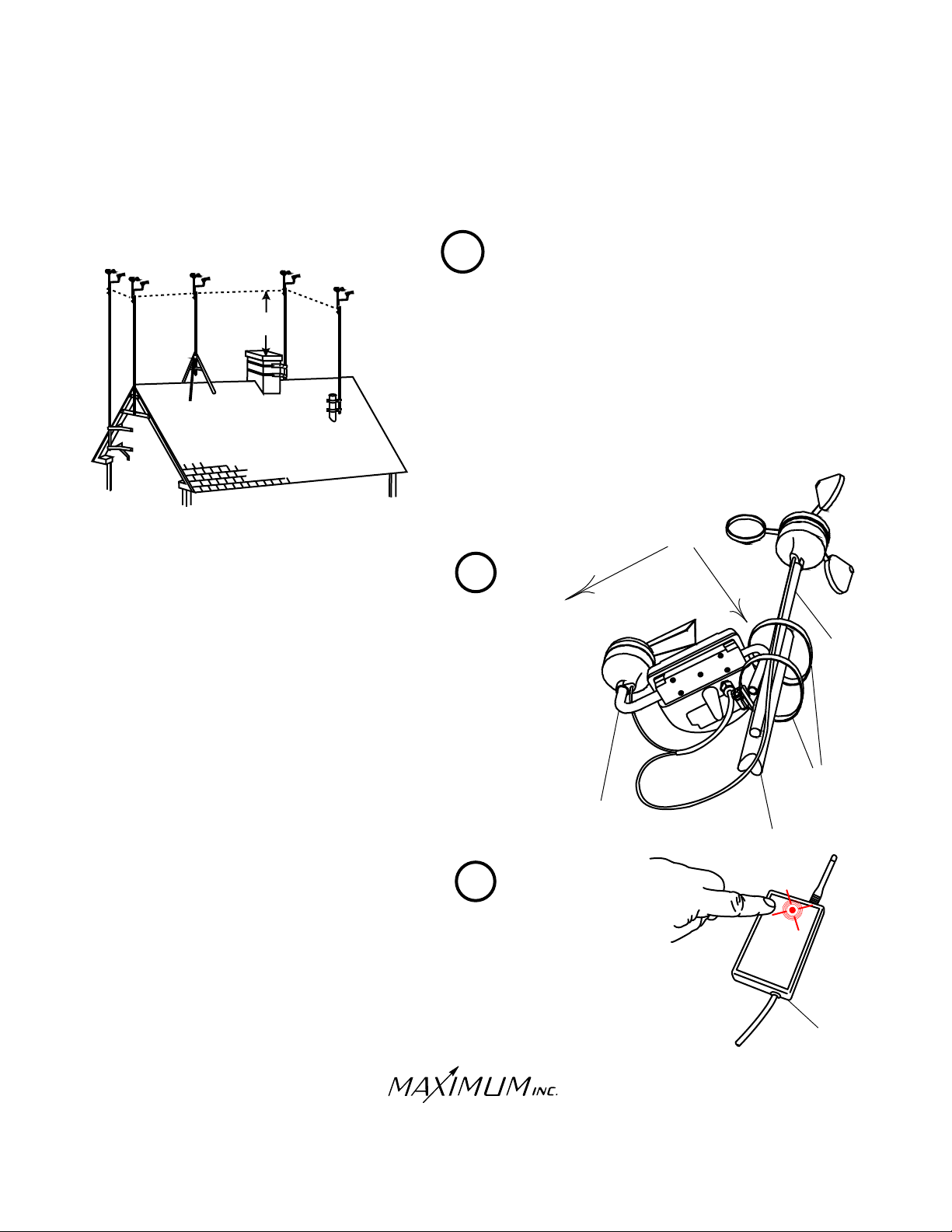
TRIPOD
MOUNT
EVE
MOUNT
WALL
MOUNT
CHIMNEY
MOUNT
8 FEET
12
VENT-PIPE
MOUNT
A mounting mast and bracket for your particular situation will need
to be purchased. Radio Shack and home supply stores often have
a selection of masts and mounting brackets. The ideal mounting
mast and bracket should provide approximately eight feet of vertical
clearance above nearby obstacles. Do not use a mounting mast
made of fiberglass or PVC plastic because of electrical grounding
considerations. Check with local building/electrical code enforcement
officer about mounting mast grounding requirements.
13
Secure the sensors and stub masts to the mounting mast with the
two hose clamps provided (see illustration). Move the completed
mast assembly as close as possible to your preferred final mounting
location. Also move the instrument meter and receiver combination
as close as possible to their final mounting location. Check to make
sure that proper communication between the receiver and transmitter
still exists by verifying that the light on the receiver is still flashing
red every two seconds. NOTE: If more than 15 minutes has passed
since the button on the wind transmitter was pushed, it will need to
be pushed again (see step 8). If the signal has been lost, move to
an alternate installation location for a better signal with the receiver
flashing every two seconds.
AST
E
STUB
MAST
S
O
U
TH
STUB
MAST
HOSE
CLAMPS
MOUNTING
MAST
14
Permanently install the mounting mast and brackets following the
manufacturer’s instructions (See illustration, step 13).
Make sure that the “z” shaped arm is facing east
and the solar panel is facing south
30 Barnet Boulevard
New Bedford, MA 02745
(508) 995-2200
Page 5
RECEIVER
Page 6
MAESTRO
WIRELESS
INSTALLATION
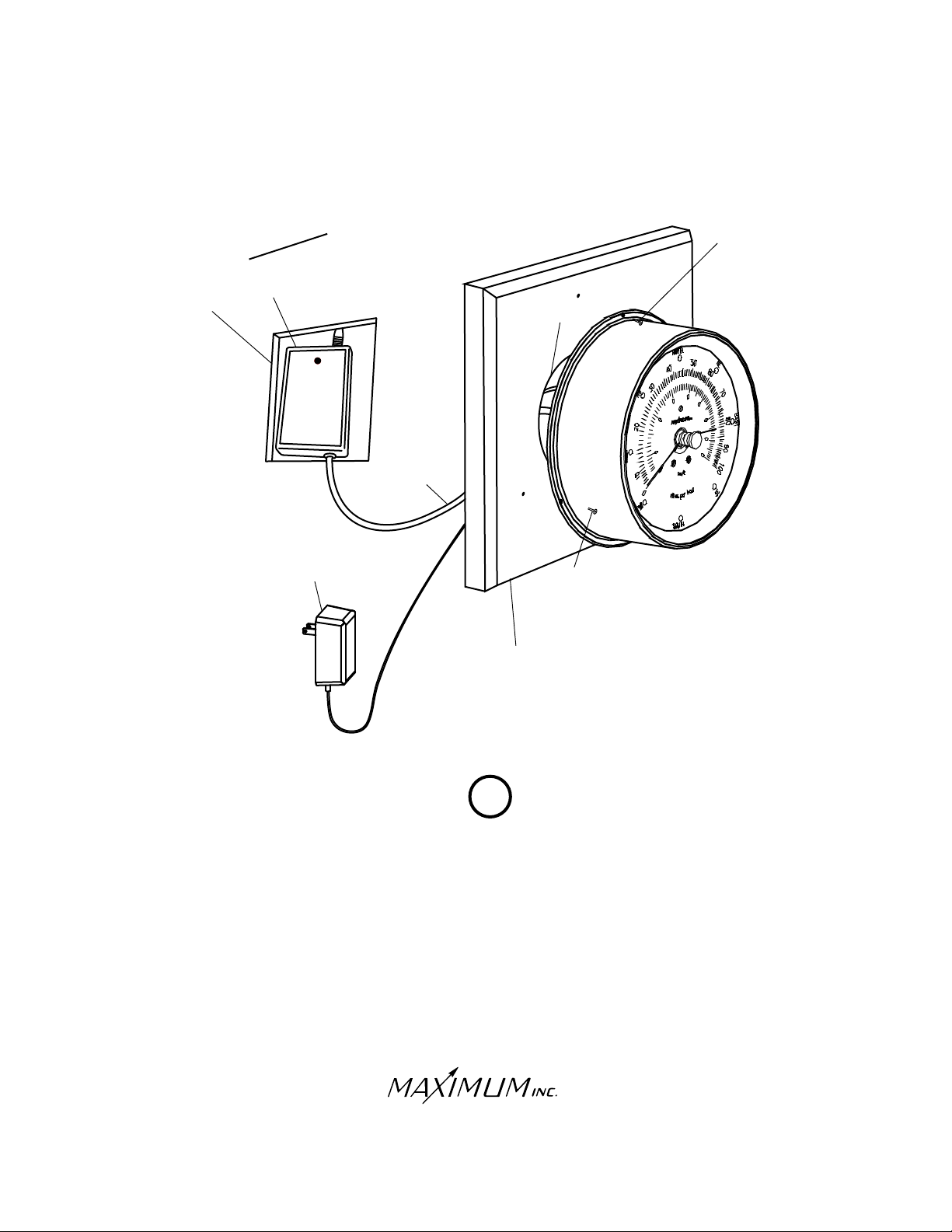
HOLE
L
WA
RECEIVER
12 VOLT
POWER
SUPPLY
L
SCREW
CABLE-HOLE
CABLES
SCREW
WOOD
PANEL
15
Mount the brass instrument meter directly over the cable hole that is also used
to route power to the instrument. For the cleanest installation, we recommend
making a hole in the wall large enough to insert the wireless receiver. We also
recommend mounting the brass meter to one of our pre-drilled mounting panels.
30 Barnet Boulevard
New Bedford, MA 02745
(508) 995-2200
Page 6
Page 7
MAESTRO
WIRELESS
OPTIONAL INSTALLATION
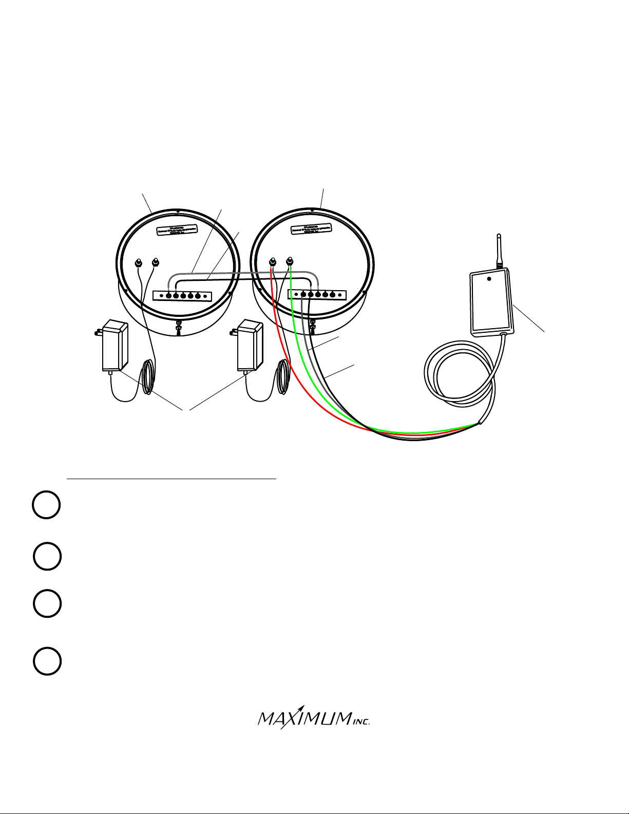
MAESTRO WITH MINI-MAX
MAESTRO
WHITE
WHITE
BLACK
2
3
1
4
5
MCO
N
I
OUT
12 VOLT
POWER
SUPPLY
MAESTRO AND MINI-MAX CONNECTIONS
MINI-MAX
2
3
1
4
5
MO
N
I
OUT
C
WHITE
WHITE
BLACK
RECEIVER
Connect the and wires from the RECEIVER to the power terminals on the back of the MINI-MAX
1
(no polarity).
RED GREEN
RED
GREEN
Connect the wires from the 12 VOLT POWER SUPPLY to the same MINI-MAX power terminals (no polarity).
On the MINI-MAX, connect the wire from the RECEIVER to TERMINAL #1 (IN) and the BLACK wire from
2
the RECEIVER to TERMINAL #2 (COM).
Connect the two instruments using the supplied grey sheathed BLACK and wires as follows:
3
A. Connect the wire from MAESTRO TERMINAL #1 (IN) to MINI-MAX TERMINAL #3 (OUT)
WHITE
WHITE
WHITE
WHITE
WHITE
WHITE
B. Connect the BLACK wire from MAESTRO TERMINAL #2 (COM) to MINI-MAX TERMINAL #2 (COM)
4
Connect the wires from the 12 VOLT POWER SUPPLY to the MAESTRO power terminals (no polarity).
30 Barnet Boulevard
New Bedford, MA 02745
(508) 995-2200
Page 7
Page 8
RAINWATCH
WIRELESS
OPTIONAL INSTALLATION
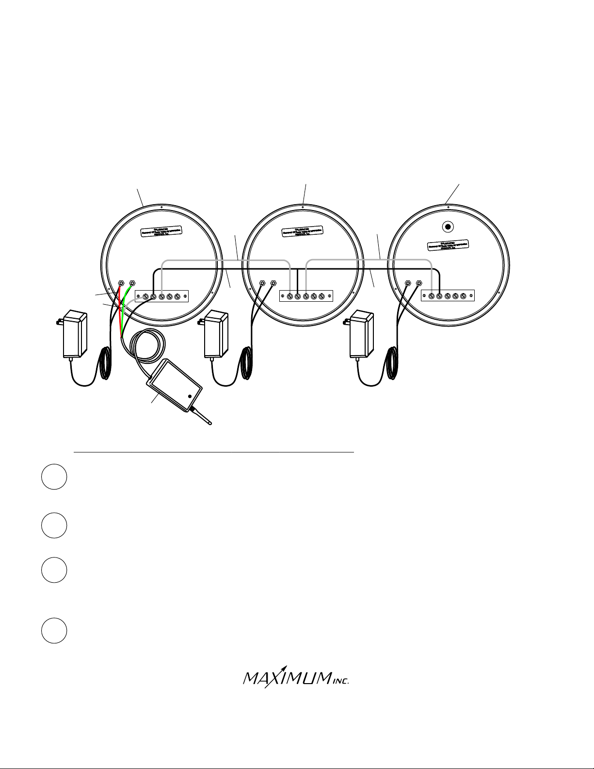
MAESTRO WITH MINI-MAX AND RAINWATCH
MINI-MAX
1 2 3 4
IN
5
OUT
COM
RED
RED
GREEN
GREEN
MAESTRO
AC ADAPTER
1 2 3 4
IN
WHITE
WHITE
AC ADAPTER
BLACK
5
OUT
COM
RECEIVER
RAINWATCH WITH MINI-MAX AND MAESTRO CONNECTIONS
WHITE
WHITE
BLACK
AC ADAPTER
RAINWATCH
1 2 3 4
IN
5
OUT
COM
Connect the and wires from the RECEIVER to the power terminals on the back of the MAESTRO
1
(no polarity).
RED GREEN
RED
GREEN
Connect the wires from the 12 VOLT POWER SUPPLY to the same MAESTRO power terminals (no polarity).
On the MAESTRO, connect the wire from the RECEIVER to TERMINAL #1 (IN) and the BLACK wire
2
from the RECEIVER to TERMINAL #2 (COM).
Connect the MAESTRO and MIN-MAX instruments using the supplied grey sheathed BLACK and wires
3
as follows:
A. Connect the wire from MINI-MAX TERMINAL #1 (IN) to MAESTRO TERMINAL #3 (OUT).
WHITE
WHITE
WHITE
WHITE
WHITE
WHITE
B. Connect the BLACK wire from MINI-MAX TERMINAL #2 (COM) to MAESTRO TERMINAL #2 (COM).
Connect the MINI-MAX and RAINWATCH instruments using the supplied grey sheathed BLACK and WHITE
4
wires as follows:
A. Connect the WHITE wire from RAINWATCH TERMINAL #1(IN) to MINI-MAX TERMINAL #3 (OUT)
WHITE
B. Connect the BLACK wire from RAINWATCH TERMINAL #2(COM) to MINI-MAX TERMINAL #2(COM).
30 Barnet Boulevard
New Bedford, MA 02745
(508) 995-2200
Page 8
WHITE
Page 9
MAESTRO
WIRELESS
OPERATION
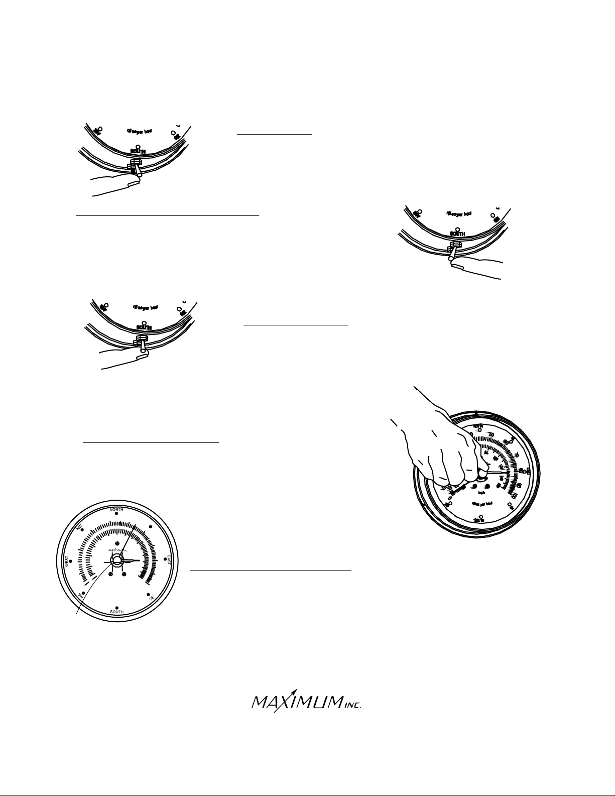
HIGHEST GUST
Holding the toggle switch to the right will display the
speed and direction of the highest gust since the
instrument was last reset.
AVERAGE WIND SPEED & DIRECTION
Lightly holding the toggle switch to the left will display the
two minute average wind speed and prevailing direction.
RESETTING MEMORY
To reset the gust register, average wind speed and direction recording,
fully depress the small push button for five seconds. The MAESTRO
will again begin storing new data.
TREND REGISTER POINTER
You can reset the Trend Register Pointer by turning the knob
located in the center of the dial face.
50
0
2
0
1
LIGHTS
40
0
3
0
6
0
4
0
1
0
0
m
i
l
e
s
60
8
0
k
m h
/
o
h
p
r
e
7
1
0
00
12
0
80
14
0
1
6
90
0
1
0
0
r
u
EXTREMELY HIGH WIND SPEEDS
If the winds exceed 100mph, the instrument will automatically switch into double mode.
Two lights in the center meter opening in the dial will flash simultaneously and the meter
reading will indicate half the wind speed (75mph = 75 X 2 = 150mph). If the winds
exceed 200mph, the instrument will automatically switch into triple mode. The two lights
in the dial will light continuously and the reading will be one third the actual wind speed
(75mph = 75 X 3 = 225mph). The MAESTRO will stay in triple mode until the wind drops
below 150mph.
30 Barnet Boulevard
New Bedford, MA 02745
(508) 995-2200
Page 9
Page 10
MAESTRO
WIRELESS
TROUBLE-SHOOTING
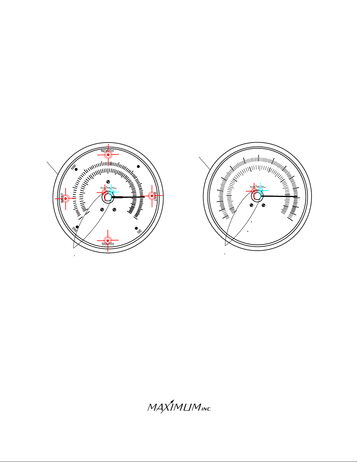
THE FOLLOWING ILLUSTRATIONS SHOW HOW THE INSTRUMENT
DIAL WILL INDICATE IMPROPER OPERATION.
NO SERIAL DATA
(Instrument has never recognized a receiver)
40
40
0
3
20
0
1
0
4
0
1
0
0
m
5
0
6
0
80
06
i
l
e
k /h
m
s
p
100
0
r
u
o
h
r
e
7
0
1
2
0
140
16
010
80
90
10
0
0
1
-
-20
-30
MINI-MAX
0
3
0
2
0
0-1
0
2
-
0
-3
F
a
h
r
50
1
0
20
3
0
4
0
cCel
ius
t
i
e
h
e
n
6
0
7
0
8
0
90
1
0
1
1
1
2
FLASHING
LED s
FLASHING
LED s
SYMPTOM:
-The pointer is in the 3 o’clock position
-The central LED’s are flashing
-The (Maestro) primary direction LED’s are illuminated
REMEDY:
-Check all wire connections (Refer to installation diagrams)
-Re-boot the system by unplugging the power
supply, wait 30 seconds, plug it back in.
-The light on the receiver will flash RED and then
GREEN
GREEN five times, indicating that the receiver is
now powered-up.
-If the instrument continues to display the error code,
call Maximum for further assistance.
Note: Depending on the origin of the problem, error
codes may not display on all instruments.
RED
30 Barnet Boulevard
New Bedford, MA 02745
(508) 995-2200
Page 10
Page 11
WIRELESS
TROUBLE-SHOOTING
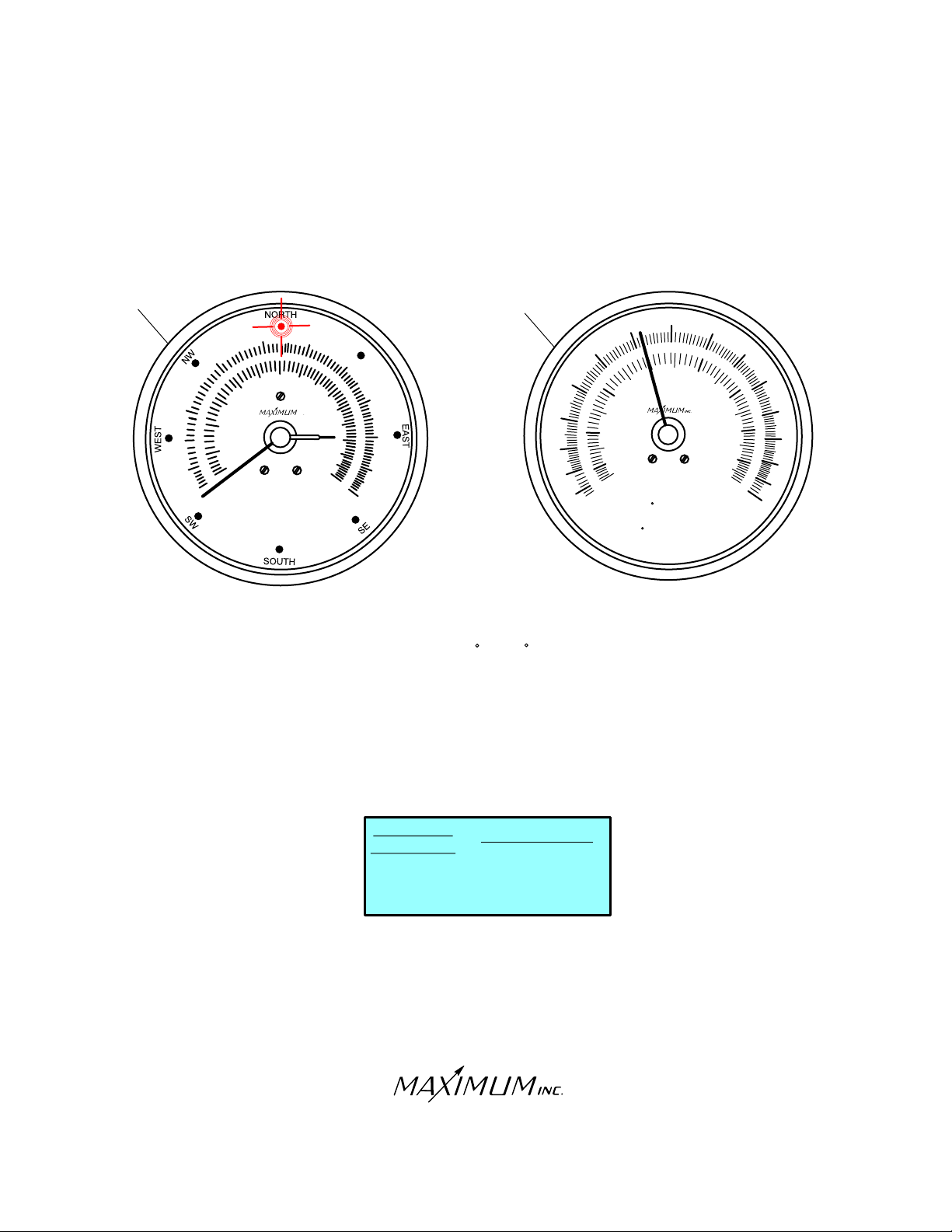
NO SIGNAL FROM ANY TRANSMITTER
(Instrument recognizes the receiver, but the receiver does not recognize the sensor(s).)
MAESTRO
MINI-MAX
40
30
60
0
2
10
40
01
0
0
m
50
60
80
10
0
hkm/
r
i
l
u
e
o
s
h
p
r
e
70
21
0
1
40
1
60
80
09
1
0
0
20
0
1
0
0
-1
-20
-
0-2
3
3
- 0
40
0
3
0
0
1
- 0
Celcius
F
a
h
r
e
05
60
10
20
t
i
e
h
n
7
0
80
3
0
40
90
10
1
1
12
SYMPTOM:
-Maestro needle points to 0 MPH
-Mini-Max needle points to 32 F (or 0 C)
REMEDY:
-Test the batteries in each external SENSOR/TRANSMITTER
and replace if necessary.
-Put the TRANSMITTER(S) into TEST MODE by pressing TEST
BUTTON in the battery compartment of TRANSMITTER.
-Remove the RECEIVER from the wall and confirm receipt of
TRANSMISSION(S) based on the color of the flashing light.
RECEIVER
INDICATOR
RED
....................WIND
RED
GREEN
GREEN
ORANGE
ORANGE
.........TEMPERATURE
TRANSMITTER
................RAIN
-If the instrument continues to display the error code, call Maximum
for further assistance.
Note: Depending on the origin of the problem, error
codes may not display on all instruments.
30 Barnet Boulevard
New Bedford, MA 02745
(508) 995-2200
Page 11
Page 12
WIRELESS
TROUBLE-SHOOTING
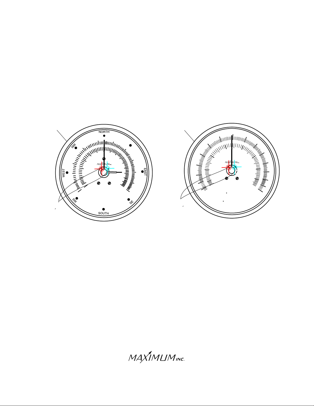
NO SIGNAL FROM WIND TRANSMITTER
(Instrument has received, then lost sensor(s) signal)
MAESTRO
FLASHING
LED s
3
0
2
10
0
MINI-MAX
0
0
4
0
40
0
1
0
m
50
60
0
80
06
i
l
e
km/h
s
100
r
u
o
h
p
r
e
70
120
1
40
1
60
8
0
09
10
0
FLASHING
1
0
0
-1
20
-
30
-
3
20
10
-
20
-
0
3
-
LED s
SYMPTOM:
-The pointer is in the 12 o’clock position.
-Central LED’s flashing.
REMEDY:
-Re-charge and/or replace the AA NiCad batteries in the WIND
TRANSMITTER.
-Put TRANSMITTER(S) into TEST MODE by pressing the TEST
BUTTON in the battery compartment of TRANSMITTER. This
should cause the LED on the receiver to flash RED every 2 seconds.
RED
-If the instrument continues to display the error code, call Maximum
for further assistance.
F
0
Celcius
a
h
r
40
e
05
06
10
t
i
e
h
n
70
02
3
0
40
80
90
10
1
1
1
2
30 Barnet Boulevard
New Bedford, MA 02745
(508) 995-2200
Page 12
Page 13
WIRELESS
TROUBLE-SHOOTING
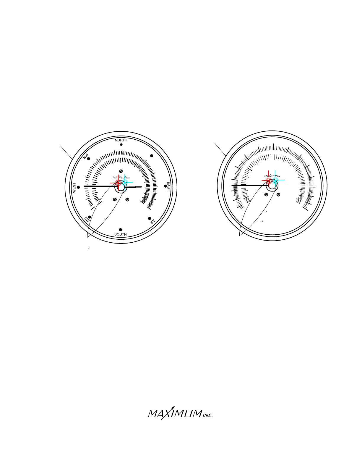
NO SIGNAL FROM TEMPERATURE TRANSMITTER
(Instrument has received, then lost sensor(s) signal)
MAESTRO
FLASHING
LED s
30
0
2
10
0
40
0
4
10
0
m
5
0
60
80
06
i
l
e
1 00
hkm/
r
u
o
s
h
p
r
e
7
0
12
0
14
0
1 0
6
8
0
9
0
1
0
0
SYMPTOM:
-The pointer is in the 9 o’clock position.
-Central LED’s flashing.
MINI-MAX
FLASHING
LED s
40
0
3
20
0
1
0
0
1
-
-20
3
- 0
0
1
- 0
-20
30
-
C lc
e
F
a
h
50
6
0
1
0
20
ius
t
i
e
r
h
e
n
70
8
30
4
0
0
90
10
1
1
12
REMEDY:
-Check and replace (if necessary) the AA Alkaline batteries in the
TEMPERATURE TRANSMITTER.
-Put TRANSMITTER(S) into TEST MODE by pressing the TEST BUTTON
in the battery compartment of the TRANSMITTER. This should cause the
LED on the receiver to flash GREEN every 4 seconds.
GREEN
-If the instrument continues to display the error code, call Maximum
for further assistance.
30 Barnet Boulevard
New Bedford, MA 02745
(508) 995-2200
Page13
Page 14
WIRELESS
TROUBLE-SHOOTING
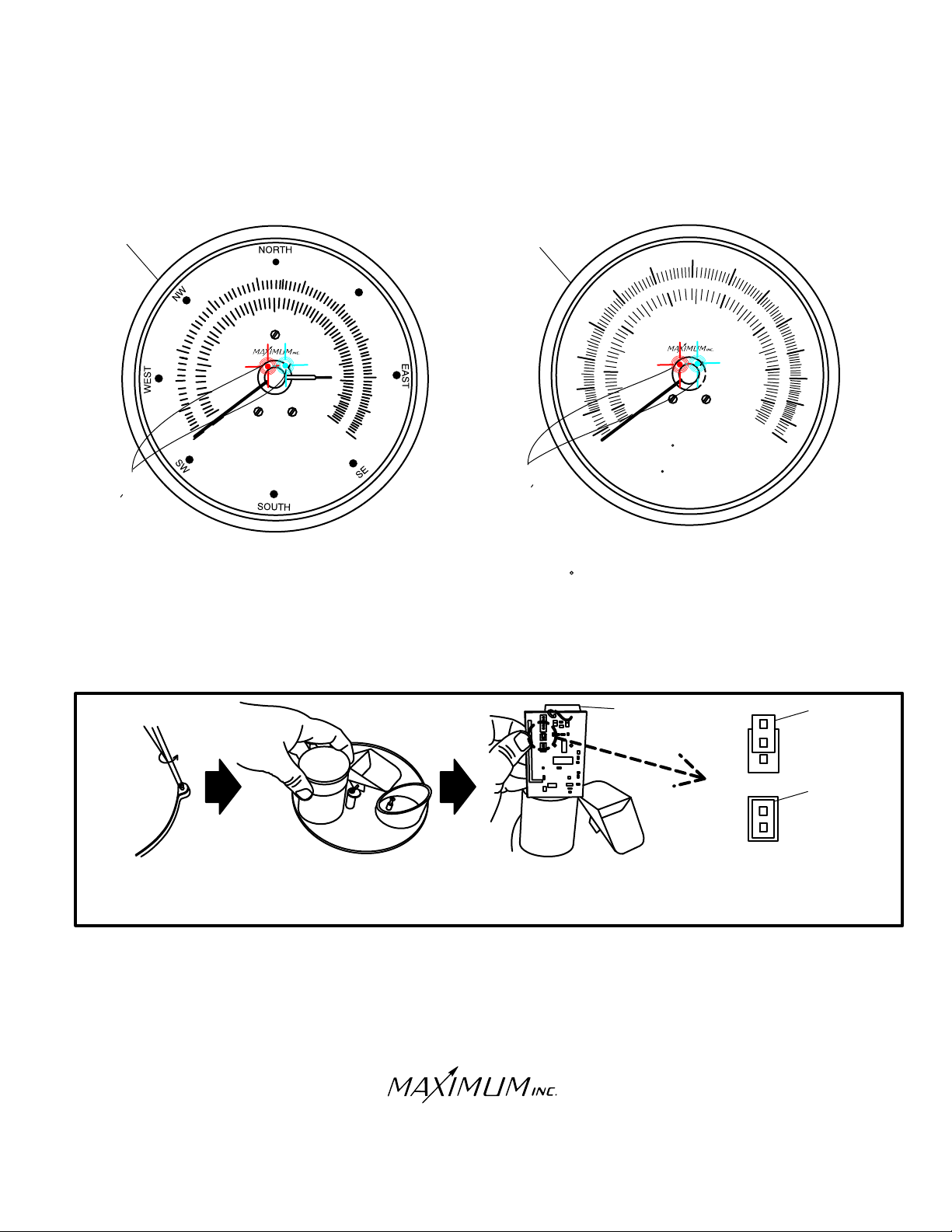
NO SIGNAL FROM RAIN TRANSMITTER
(Instrument has received, then lost sensor(s) signal)
MAESTRO
FLASHING
LED s
0
4
30
6
20
10
40
01
0
0
m
50
60
8
0
0
0
01
0
km/h
r
i
l
u
e
o
s
h
p
r
e
7
0
120
14
0
16
8
0
9
0
10
0
MINI-MAX
FLASHING
LED s
40
0
3
0
2
01
0
0
1
-
-20
0
3
-
0
-10
20
-
-30
F
a
h
r
5
0
1
0
2
0
30
4
0
l
iuCe c
s
t
i
e
h
e
n
SYMPTOM:
-Maestro needle points to 0 MPH.
-Mini-Max needle points to -35.
-Central LED’s flashing.
REMEDY:
-Remove and test the AA Alkaline batteries in the RAIN TRANSMITTER. If dead, replace batteries and check
operation. If good, continue to next step.
-Put the RAIN TRANSMITTER into TEST MODE by removing the batteries, then moving the jumper on the
RAIN TRANSMITTER circuit board to cover both pins of the 2-pin terminal.
60
70
80
9
0
1
0
11
21
BATTERY
JUMPER
COMPARTMENT
OPERATING
MODE
JUMPER
TEST
MODE
REMOVE OUTER
CASE BY LOOSENING
FOUR SCREWS
SLIP CAP OFF
CYLINDER HOUSING
TRANSMITTER
CIRCUIT BOARD
REMOVE
TRANSMITTER
CIRCUIT BOARD
FROM CYLINDER
SET JUMPER TO
TEST MODE BY
COVERING BOTH PINS
-Re-install the AA Alkaline batteries in the RAIN TRANSMITTER once the jumper has been moved.
-Check LED on receiver to make sure it is blinking ORANGE every 4 seconds.
ORANGE
-Check the instruments to see if the error has been corrected.
-Unlike the WIND and TEMPERATURE TRANSMITTERS, the RAIN TRANSMITTER will not automatically
exit test MODE after 15 minutes. Therefore, you must take the rain transmitter out of test mode manually. To
do so: remove the batteries, then move the jumper on the RAIN TRANSMITTER circuit board back to covering
only one pin of the 2-pin terminal (it does not matter which pin is covered). Re-install the batteries and cover.
-If the instrument continues to display the error code, call Maximum for further assistance.
30 Barnet Boulevard
New Bedford, MA 02745
(508) 995-2200
Page 14
Page 15
WIRELESS
FCC NOTICE
Warning: Changes or modifications to this equipment not expressly approved by Maximum,
Inc. in writing as the party responsible for compliance could void the user’s authority to
operate the equipment.
NOTE: This equipment has been tested and found to comply with the limits for a CLASS B
Digital Device, pursuant to Part 15 of the FCC Rules. These limits are designed to provide
reasonable protection against harmful interference in a residential installation. This equipment
generates, uses and can radiate radio frequency energy and, if not installed and used in
accordance with the instructions, may cause harmful interference to radio communications.
However, there is no guarantee that interference will not occur in a particular installation. If
this equipment does cause harmful interference to radio or television reception, which can
be determined by turning the equipment off and on, the user is encouraged to try to correct
the interference by one or more of the following measures:
Reorient or relocate the receiving antenna.
Increase the separation between the equipment and the receiver.
Connect the equipment into an outlet on a circuit different from that to which the
receiver is connected.
Consult the dealer or an experienced radio/TV technician for help.
NOTES
30 Barnet Boulevard
New Bedford, MA 02745
(508) 995-2200
Page 15
Page 16

R
W E A T H E R I N S T R U M E N T S
Electrical Damage - Common Causes & Recommended Prevention
Electrical damage can be caused by many different factors. Below are some of the more common causes and
some suggested methods of minimizing potential problems.
Common Causes:
Storm Activity - lightening in your area can do damage to your instruments in different ways. The obvious
way is due to a direct or nearby strike. In addition, lightening storms, dust storms, dry snowstorms and
strong dry winds can all cause static electricity to build up on and around your external sensors. Regardless
of the cause, this built up electricity itself through the cable connecting the external sensors to
the instrument.
Power Surges - A surge may come from the electric company’s switching generators or power grids, from
local industries or after power interruption when accumulated power suddenly surges back through AC lines.
Even the on-and-off switching of large electrical appliances, such as refrigerators or clothes dryers can
create damaging fluctuations. This is especially true with sensitive weather recording devices.
Yourself - Are you constantly giving and/or receiving a shock every time you touch a doorknob or other
person? If so, you have a great deal of static electricity in your environment. In either case, it is possible for a
person to carry enough of a charge to damage an instrument.
Recommended Prevention:
Ground Your Mounting Mast – IMPORTANT: PVC and fiberglass are not recommended mast materials as
they can store high amounts of static electricity within themselves. It is recommended that you follow the
grounding instructions that came with your mounting mast, while also maintaining accordance to your local
Electric Code. In the absence of instructions for your mast system, the following generic guidelines from the
National Electric Code may be helpful.
The NEC requires that the antenna mast and mount be grounded directly. No splices or connections are
1)
allowed in the ground wire between the mast and the ground rod.
2)
Attach one end of a No. 8 (or thicker) copper or aluminum ground wire to the antenna mast. Note: As static
electricity issues are more common for weather sensors than direct lightening strikes, consider installing the
ground wire as physically close to the wind sensors as possible to best combat static electricity issues. For
multi-piece (or telescoping) masts, consider connecting the ground to each separate section of the mast.
For painted or coated masts, scrape off the coating around the area where the contact will be made. This
3)
will ensure a good, solid connection. (Once the ground is attached to the mast, any scraped off portion that
is exposed should be recoated with paint or other sealant.)
Next, run the ground wire to ground as directly as possible. Standard wire staples can be used to secure the
4)
ground wire against the side of the house. Avoid making 90° or sharper turns with the ground wire. A
lightning charge has difficulty making such a turn and therefore may discharge into the house. Make ground
wire bends as smooth and as gradual as possible.
5)
The ground wire must be connected to a ground rod. Water pipes or plumbing fixtures are not acceptable.
A good copper-coated steel ground rod driven at least 3 feet into the ground is required. Special clamps that
provide a solid connection between the ground wire and ground rod should be used
Use Surge Protectors - for the AC adapter, a UL 1449 rated surge protector with EMI/RFI filtering is
recommended. This rating will be clearly listed on the packaging of all good quality surge protector.
Discharge Yourself - If the instruments are located in an environment where static electricity is a problem,
make sure that you discharge yourself before touching the instrument(s). The shock that you get from
touching a doorknob or another person can often be sufficient to damage an instrument.
30 SAMUEL BARNET BOULEVARD NEW BEDFORD, MASSACHUSETTS 02745 U.S.A.
TEL. 508.995.2200 WWW.MAXIMUM-INC.COM FAX 800.989.2580
Page 16
 Loading...