

Maxent MX-27X2 END-USER WARRANTY
LCD Flat Panel
27” LCD Monitor
Owners Manual

Important Safety Instructions
WARNING
RISK OF ELECTRIC SHOCK
DO NOT OPEN
WARNING: To reduce the risk of electric shock, do not remove the front or back covers.
No user-serviceable parts inside. Refer servicing to qualified service personnel only.
The lightning flash with arrow-head
within a triangle is intended to inform
the user that parts inside the product
are a risk of electric shock.
The exclamation point within a triangle
is intended to tell the user that important
operating and servicing instructions are
explained.
Special Notices
Certain programs may be copyrighted and any unauthorized recording in whole or in part may be in violation
of copyright laws in the U.S. and Canada.
FCC/CSA regulations state that any unauthorized modifications to this display may void user authority to
operate it.
Warnings & Precautions
To prevent damage which may result in fire or shock hazard, do not expose this product to rain or moisture.
To prevent electric shock, do not remove cover. No user serviceable parts are inside. Refer servicing to
qualified service personnel only.
Keep display away from excessive dust, high temperature, moisture or direct sunlight.
Use in a well-ventilated area and do not cover ventilation openings.
Unauthorized modifications to this equipment or usage of an unshielded connecting cable may cause
excessive interference.
When the display is not in use, disconnect it from the electric outlet.
If the picture displayed is in any way abnormal, turn off the unit and disconnect it from the electric outlet.
Verify your signal wire connections and reconnect the display to the electric outlet.
Do not place this product on an unstable cart, stand or table. The product may fall, causing serious
damage.
Do not place the unit on a bed, sofa, rug, or other similar surfaces.
Never place the unit near or over a radiator or heat source.
Do not install unit in an enclosed area unless proper ventilation is provided.
The unit should be operated from the type of power source indicated on the label. If the type of available
power is unknown, consult your dealer or local power company.
The unit is equipped with a 3-pin grounded plug. The plug will only fit into a grounded power outlet. This is a
safety feature. If you are unable to insert the plug into the outlet, contact your electrician. Do not alter this
plug as this will defeat the safety feature. Power cord not lighter than H05VV-F, 3G, 0.75mm2 shall be used.
Do not rest objects on the power cord & avoid placing power cord near high traffic areas.
Do not overload wall outlets and extension cords as this can result in a risk of fire or electric shock.
Unplug the display from the electric outlet and disconnect the antenna/cable TV system during a lightning
storm or when left unused for long periods of time. This will prevent damage to the display caused by
lightning and power-line surges.
Avoid overhead power lines. An outdoor antenna system should not be placed in the vicinity of overhead
power lines, electric lights, or power circuits. When installing an outdoor antenna, be careful to not touch
any power lines or circuits as contact with these lines can be fatal.
Do not insert any foreign objects through the ventilation openings to the display. It may touch dangerous
voltage points or damage parts.
2

Important Safety Instructions
If an outdoor antenna or cable system is connected to the display, be sure the antenna or cable system is
grounded to provide some protection against voltage surges and static charge buildups. Section 810 of the
National Electrical Code, ANSI/NFPA No.70-1984, provides information about proper grounding of the mast
and supporting structure, grounding of the lead-in wire to an antenna discharge unit, size of grounding
conductors, location of antenna discharge unit, connection to grounding electrodes, and requirements for the
grounding electrode.
If this display is equipped with separate speakers, please remove the speakers prior to moving the display.
Moving the display with the speakers attached may cause damage or injury.
Disconnect the unit from the main supply and refer servicing to qualified service personnel under the follow-
ing conditions:
- Power cord or plug is damaged or frayed.
- Liquid has been spilled into the product and/or the unit has been exposed to water or moisture.
- Unit does not operate normally when the operating instructions are not followed. Adjust only those
controls that are covered by the operating instructions, improper adjustment of other controls may result
in damage which often requires extensive work by a qualified technician to restore the unit to normal
operation.
- Unit has been dropped or the cabinet has been damaged.
- Unit exhibits a distinct change in performance, indicating a need for service.
Cleaning & Maintenance
Disconnect from the electric outlet before cleaning. Do not use liquid or aerosol cleaners. Use only a slightly
damp cloth for cleaning.
Special Warranty Information
Cell Defects
Although the display panels are produced with more than 99% percent active cells, there may be some cells
that do not produce light or remain lit. This is considered normal and not a manufacturer defect.
3

Regulatory Notice
FCC Statement
The Federal Communications Commission Radio Frequency Interference Statement includes the following
warning:
This equipment has been tested and found to comply with the limits for a Class B digital device, pursuant to Part
15 of the FCC Rules. These limits are designed to provide reasonable protection against harmful interference in
a residential installation. This equipment generates, uses, and can radiate radio frequency energy and, if not
installed and used in accordance with the instructions, may cause harmful interference to radio
communications. However, there is no guarantee that interference will not occur in a particular installation.
If this equipment does cause harmful interference to radio or television receptions, which can be determined by
turning the equipment off and on, the user is encouraged to try to correct the interference by one or more of the
following measures:
- Reorient or relocate the receiving antenna.
- Increase the separation between the equipment and receiver.
- Connect the equipment into an outlet on a circuit different from that to which the receiver is connected.
- Consult the dealer or an experienced radio/TV technician for help.
Warning
User must use shielded signal interface cables to maintain FCC compliance for the product. Provided with this
display is a detachable power supply cord with IEC320 style terminations. It may be suitable for connection to
any UL Listed personal computer with similar configuration. Before making the connection, make sure the
voltage rating of the computer convenience outlet is the same as the monitor and that the ampere rating
of the computer convenience outlet is equal to or exceeds the monitor voltage rating. For 120 Volt applications,
use only UL Listed detachable power cord with NEMA configuration 5-15P type (parallel blades) plug cap. For
240 Volt applications use only UL Listed Detachable power supply cord with NEMA configuration 6015P type
(tandem blades) plug cap.
IC Compliance Notice
This Class B digital apparatus meets all requirements of the Canadian Interference-Causing Equipment Regulations of ICES-003.
Cet appareil Numerique de classe B respecte toutes les exigences du Reglemont NMB-03 sur les equipements
produisant des interferences au Canada.
Notice de Conformit IC
Cet appareil numerique de classe B respecte toutes les exigences du Reglement ICES-003 sur les equipements
produisant des interferences au Canada.
4

Table of Contents
Important Safety Instructions ................................................................................................................... 2
Special Notices................................................................................................................................. 2
Warnings & Precautions ................................................................................................................... 2
Cleaning & Maintenance ................................................................................................................... 3
Special Warranty Info ........................................................................................................................ 3
Regulatory Notice .................................................................................................................................... 4
Getting to Know Your Display .................................................................................................................. 7
Package Contents ............................................................................................................................ 8
Optional Accessories ........................................................................................................................ 8
Front Panel Controls ......................................................................................................................... 9
Rear Panel Connections ................................................................................................................... 10
Remote Control ................................................................................................................................. 11
Display Connections ............................................................................................................................... 13
Connecting TV or CATV .................................................................................................................... 14
Connecting a VCR ............................................................................................................................ 14
Connecting a DVD ............................................................................................................................. 15
Connecting a Set-Top Box ................................................................................................................ 17
External Audio Connections .............................................................................................................. 18
Connecting a Subwoofer ................................................................................................................... 19
Connecting a PC .............................................................................................................................. 19
RS-232 Connection ........................................................................................................................... 22
Basic Operations ..................................................................................................................................... 25
Powering On/Off ................................................................................................................................26
Changing Inputs ................................................................................................................................26
Volume Adjustment ........................................................................................................................... 27
On-Screen Display Menu .................................................................................................................. 28
On-Screen Status Display................................................................................................................. 29
Understanding Widescreen Modes .................................................................................................... 30
Changing Aspect Ratios .................................................................................................................... 31
Picture Controls ...................................................................................................................................... 33
Adjusting Picture Settings ................................................................................................................ 34
Picture-in-Picture / Side-by-Side Picture ........................................................................................... 36
Selecting Color Temperature ............................................................................................................. 40
Adjusting Screen Size ...................................................................................................................... 40
Fine Tuning RGB Mode ..................................................................................................................... 42
Sound Controls ....................................................................................................................................... 43
Adjusting Sound Settings ................................................................................................................. 44
Using Surround Sound ...................................................................................................................... 46
Using BBE Sound ............................................................................................................................. 46
Built-in Amplification (Speaker) .......................................................................................................... 47
Using an External Subwoofer ............................................................................................................ 48
Fixed / Variable Audio Output ........................................................................................................... 48
Advanced Functions ................................................................................................................................49
Sleep Timer ...................................................................................................................................... 50
OSD Menu Language ........................................................................................................................ 51
Power Save Mode ............................................................................................................................. 52
System Passcode ............................................................................................................................ 52
Information Display............................................................................................................................ 54
5

Table of Contents
TV Functions........................................................................................................................................... 55
Memorizing Channels ....................................................................................................................... 56
On-Screen Status Display (TV Mode) ............................................................................................... 58
Blue Back ......................................................................................................................................... 59
Changing Channels ........................................................................................................................... 59
MTS ................................................................................................................................................. 60
Closed Captioning ............................................................................................................................. 61
V-Chip ............................................................................................................................................... 62
Favorite Channel Programming .......................................................................................................... 65
Quick View ....................................................................................................................................... 66
Channel Lock .................................................................................................................................... 66
Understanding HDTV ......................................................................................................................... 68
Appendix ................................................................................................................................................. 71
Troubleshooting ................................................................................................................................72
Wall Mount Instructions .................................................................................................................... 73
Specifications ................................................................................................................................... 75
Index ................................................................................................................................................ 81
6

Flat Panel Monitor
Getting to Know
Your Display
7
Getting to Know Your Display
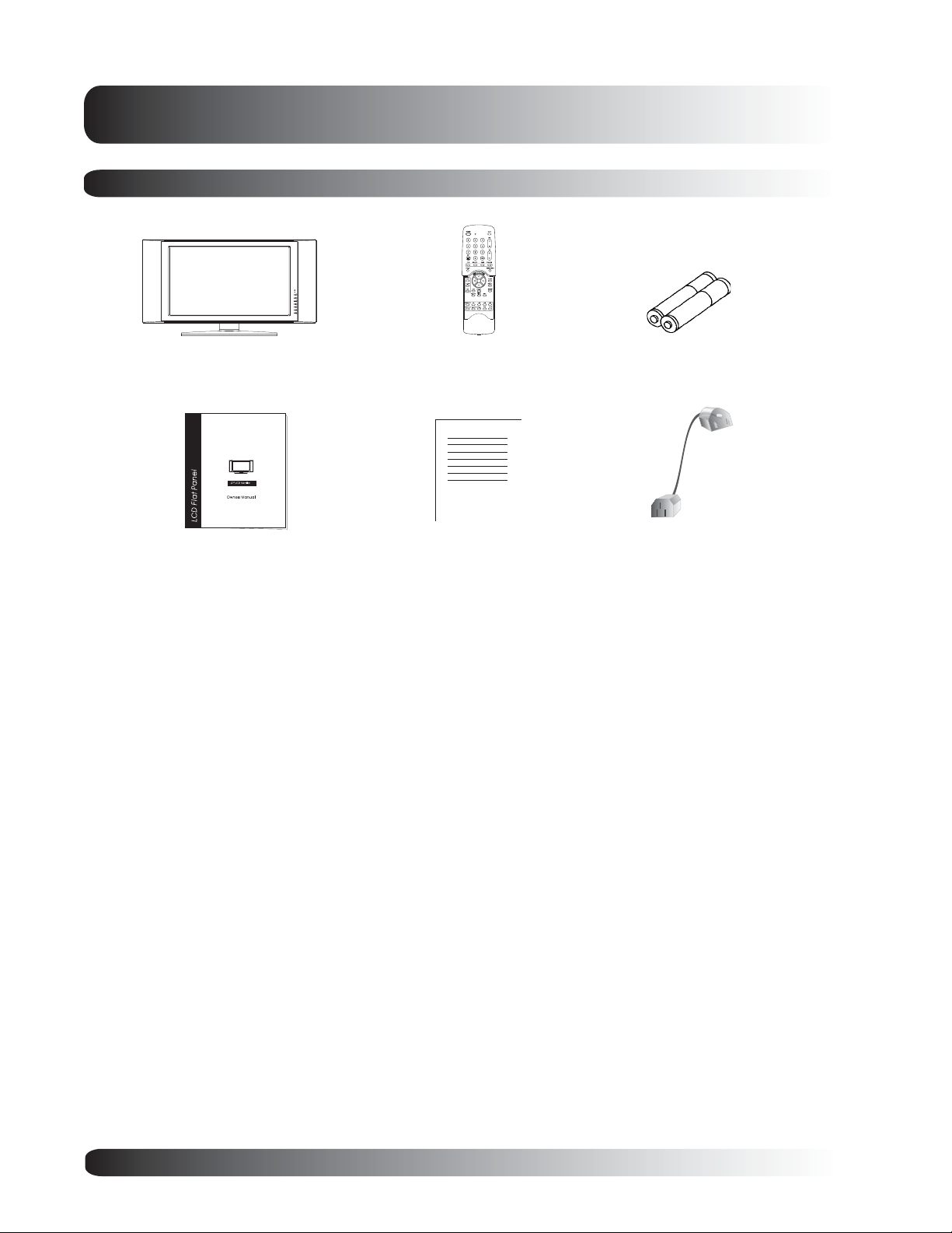
Package Contents
Flat Panel Display Remote Control
User Manual Warranty Card
Batteries
AC Power Cord
8
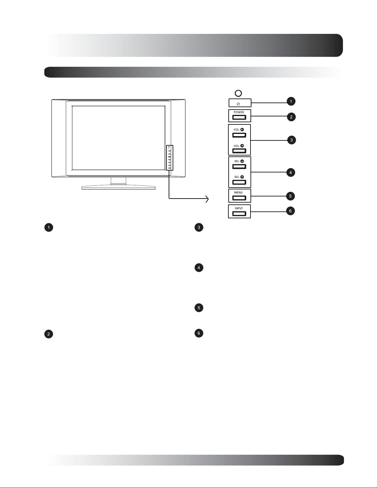
Front Panel Controls
Getting to Know Your Display
Status LED
Not Illuminated - No AC Power detected
If the main power switch (rear of panel) is turned off,
this LED will not illuminate.
Orange - Standby (Power OFF) with AC power
detected
The LED will illuminate in orange color if the monitor
is shut-off but the main power cord is plugged into
the back of the unit.
Flashing/Solid Green
The LED will flash green for approximately 3
seconds before turning solid green. This is to
indicate the display is powering up prior to
displaying full picture.
Power (Standby) Button
Turns power on/off from standby mode. There is a
wait period between on/off cycles.
Volume Adjustment Buttons
Use these buttons to adjust volume up and down.
These keys also serve as navigation and adjustment keys when On Screen Display menu is
engaged.
Select Buttons
Use these buttons to navigate through the the On
Screen Display menu. If an optional TV tuner is
intalled, these buttons also function as Channel Up/
Down.
Menu Button
Use this button to engage the On Screen Display
menu.
Input Button
Use this button to switch between available inputs.
9
Getting to Know Your Display
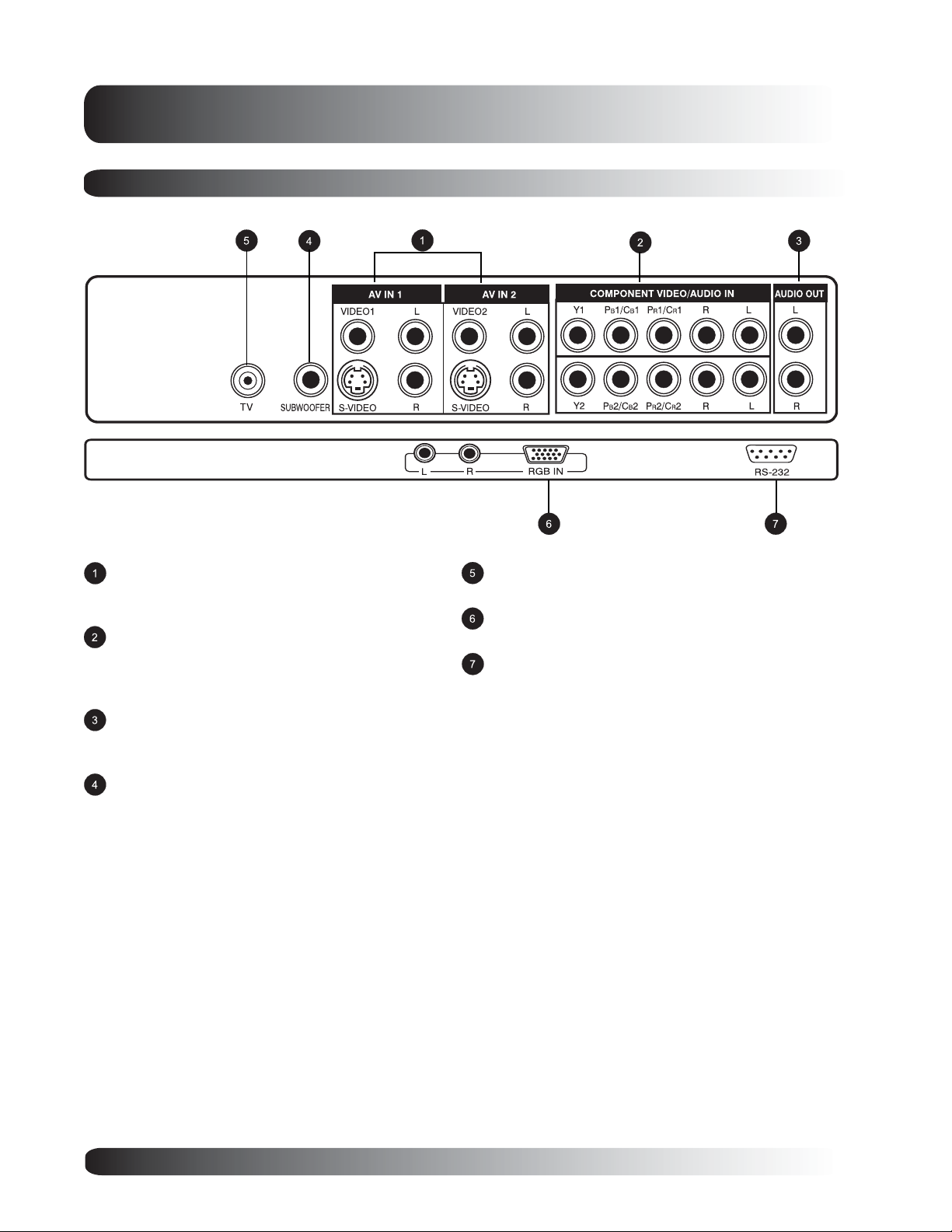
Rear Panel Connections
Composite / S-Video Inputs
Connect Composite or S-Video signals from
external sources such VCRs or DVD players.
Component Video Inputs
Auto-detecting component video inputs (Y/Pb/Pr or
Y/Cb/Cr) for connecting to the component output
jacks of a DVD player or Set-Top Box.
Audio Output
Variable or fixed audio output jacks for connecting
to an external audio amplifier.
Subwoofer Output
Variable or fixed low-frequency audio output jack for
connecting to an external amplified subwoofer.
Antenna Jack
Connect to TV or CATV antenna.
RGB Input
Connect to RGB output of computer or Set-Top box.
RS-232 Connector
Connect to a computer serial port.
10
Getting to Know Your Display
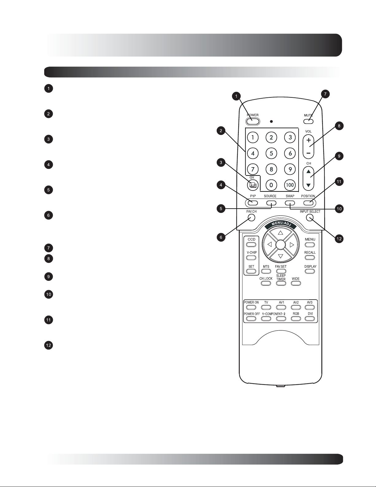
Remote Control
Standby Power On/Off
Push this button to turn on the monitor from Standby
mode. Push it again to turn off to Standby mode.
Number Keypad
Use number keypad to select the TV channel you want to
watch.
QuickView
Use QuickView key to recall the last TV channel watched.
(See Page 66)
PIP (Picture-in-Picture Button)
Turns on PIP (Picture-in-Picture) mode and POP (Side-by-
Side) picture mode. (See Page 36)
PIP/POP Source
Changes the input source of the PIP or POP sub-window.
(See Page 37)
Favorite Channel
Recalls TV channels programmed using favorite channel
memory.
(See Page 65)
Sound Mute On/Off
Volume +/-
Turns volume up or down.
Channel UP/DOWN
Change TV channels sequentially by pressing +/-.
Swap
This key swaps the main and sub picture windows under
PIP or POP modes. (See page 38)
PIP Position
This key changes the PIP sub-window to 4 different corner
locations. (See Page 38)
Input Select
Press to select input signal modes sequentially. (See
Page 26)
11
Getting to Know Your Display
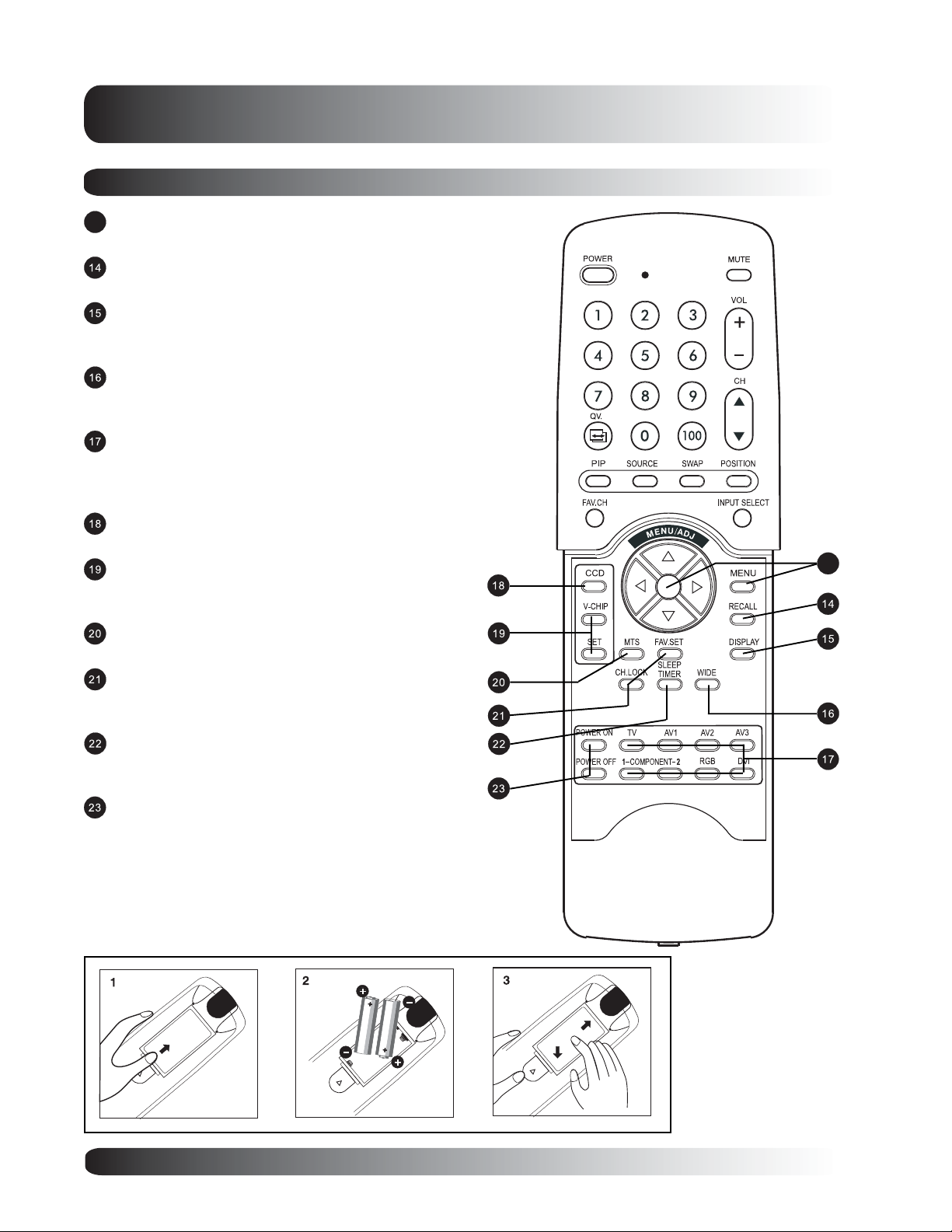
Remote Control
Menu
13
Engages the OSD menu.
Recall
Recalls default picture settings. (See Page 34)
Display
Press to show the status of the monitor. (See Page
29)
WIDE
Toggles between various aspect ratio settings. (See
Page 31)
Direct Input Selection Keys
Directly change input signal selection by pressing the
appropriate key. (Note:DVI key is not applicable to this
monitor.)
Closed Captioning
Turns on Closed Caption Mode. (See Page 61)
V-Chip
Engages V-Chip protection circuitry settings. (See
Page 62)
MTS Stereo
Engages MTS stereo reception for TV. (See Page 60)
Channel Lock / Fav. Set
Engages Channel Lock and Favorite Channel Setup
Menu. (See Page 65)
Sleep Timer
Engages Sleep Timer Settings.
(See Page 50)
Discrete Power ON/OFF
Press OFF to send monitor into Standby mode.
Press ON to power on from standby mode.
13
Battery Installation
12

Flat Panel Monitor
Display
Connections
13
 Loading...