

Maxent MX-27X1 END-USER WARRANTY
27” / 30” LCD Monitor
Owners Manual
LCD Flat Panel
Important Safety Instructions
WARNING
RISK OF ELECTRIC SHOCK
DO NOT OPEN
WARNING: To reduce the risk of electric shock, do not remove the front or back covers.
No user-serviceable parts inside. Refer servicing to qualified service personnel only.
The lightning flash with arrow-head
within a triangle is intended to inform
the user that parts inside the product
are a risk of electric shock.
The exclamation point within a triangle
is intended to tell the user that important
operating and servicing instructions are
explained.
Special Notices
Certain programs may be copyrighted and any unauthorized recording in whole or in part may be in violation
of copyright laws in the U.S. and Canada.
FCC/CSA regulations state that any unauthorized modifications to this display may void user authority to
operate it.
Warnings & Precautions
To prevent damage which may result in fire or shock hazard, do not expose this product to rain or moisture.
To prevent electric shock, do not remove cover. No user serviceable parts are inside. Refer servicing to
qualified service personnel only.
Keep display away from excessive dust, high temperature, moisture or direct sunlight.
Use in a well-ventilated area and do not cover ventilation openings.
Unauthorized modifications to this equipment or usage of an unshielded connecting cable may cause
excessive interference.
When the display is not in use, disconnect it from the electric outlet.
If the picture displayed is in any way abnormal, turn off the unit and disconnect it from the electric outlet.
Verify your signal wire connections and reconnect the display to the electric outlet.
Do not place this product on an unstable cart, stand or table. The product may fall, causing serious
damage.
Do not place the unit on a bed, sofa, rug, or other similar surfaces.
Never place the unit near or over a radiator or heat source.
Do not install unit in an enclosed area unless proper ventilation is provided.
The unit should be operated from the type of power source indicated on the label. If the type of available
power is unknown, consult your dealer or local power company.
The unit is equipped with a 3-pin grounded plug. The plug will only fit into a grounded power outlet. This is a
safety feature. If you are unable to insert the plug into the outlet, contact your electrician. Do not alter this
plug as this will defeat the safety feature. Please note the diameter of power cord should not be smaller than
0.75 mm2 (H05VV-F, 3G) when you replace equipped power cord.
Do not rest objects on the power cord & avoid placing power cord near high traffic areas.
Do not overload wall outlets and extension cords as this can result in a risk of fire or electric shock.
Unplug the display from the electric outlet and disconnect the antenna/cable TV system during a lightning
storm or when left unused for long periods of time. This will prevent damage to the display caused by
lightning and power-line surges.
Avoid overhead power lines. An outdoor antenna system should not be placed in the vicinity of overhead
power lines, electric lights, or power circuits. When installing an outdoor antenna, be careful to not touch
any power lines or circuits as contact with these lines can be fatal.
Do not insert any foreign objects through the ventilation openings to the display. It may touch dangerous
voltage points or damage parts.
2

Important Safety Instructions
! If an outdoor antenna or cable system is connected to the display, be sure the antenna or cable system is
grounded to provide some protection against voltage surges and static charge buildups. Section 810 of the
National Electrical Code, ANSI/NFPA No.70-1984, provides information about proper grounding of the mast
and supporting structure, grounding of the lead-in wire to an antenna discharge unit, size of grounding
conductors, location of antenna discharge unit, connection to grounding electrodes, and requirements for the
grounding electrode.
! If this display is equipped with separate speakers, please remove the speakers prior to moving the display.
Moving the display with the speakers attached may cause damage or injury.
! Disconnect the unit from the main supply and refer servicing to qualified service personnel under the follow-
ing conditions:
- Power cord or plug is damaged or frayed.
- Liquid has been spilled into the product and/or the unit has been exposed to water or moisture.
- Unit does not operate normally when the operating instructions are not followed. Adjust only those
controls that are covered by the operating instructions, improper adjustment of other controls may result
in damage which often requires extensive work by a qualified technician to restore the unit to normal
operation.
- Unit has been dropped or the cabinet has been damaged.
- Unit exhibits a distinct change in performance, indicating a need for service.
Cleaning & Maintenance
! Disconnect from the electric outlet before cleaning. Do not use liquid or aerosol cleaners. Use only a slightly
damp cloth for cleaning.
Special Warranty Information
Cell Defects
! Although the display panels are produced with more than 99% percent active cells, there may be some cells
that do not produce light or remain lit. This is considered normal and not a manufacturer defect.
3

Regulatory Notice
FCC Statement
The Federal Communications Commission Radio Frequency Interference Statement includes the following
warning:
This equipment has been tested and found to comply with the limits for a Class B digital device, pursuant to Part
15 of the FCC Rules. These limits are designed to provide reasonable protection against harmful interference in
a residential installation. This equipment generates, uses, and can radiate radio frequency energy and, if not
installed and used in accordance with the instructions, may cause harmful interference to radio
communications. However, there is no guarantee that interference will not occur in a particular installation.
If this equipment does cause harmful interference to radio or television receptions, which can be determined by
turning the equipment off and on, the user is encouraged to try to correct the interference by one or more of the
following measures:
- Reorient or relocate the receiving antenna.
- Increase the separation between the equipment and receiver.
- Connect the equipment into an outlet on a circuit different from that to which the receiver is connected.
- Consult the dealer or an experienced radio/TV technician for help.
Warning
User must use shielded signal interface cables to maintain FCC compliance for the product. Provided with this
display is a detachable power supply cord with IEC320 style terminations. It may be suitable for connection to
any UL Listed personal computer with similar configuration. Before making the connection, make sure the
voltage rating of the computer convenience outlet is the same as the monitor and that the ampere rating
of the computer convenience outlet is equal to or exceeds the monitor voltage rating. For 120 Volt applications,
use only UL Listed detachable power cord with NEMA configuration 5-15P type (parallel blades) plug cap. For
240 Volt applications use only UL Listed Detachable power supply cord with NEMA configuration 6015P type
(tandem blades) plug cap.
IC Compliance Notice
This Class B digital apparatus meets all requirements of the Canadian Interference-Causing Equipment Regulations of ICES-003.
Cet appareil Numerique de classe B respecte toutes les exigences du Reglemont NMB-03 sur les equipements
produisant des interferences au Canada.
Notice de Conformit IC
Cet appareil numerique de classe B respecte toutes les exigences du Reglement ICES-003 sur les equipements
produisant des interferences au Canada.
4

Table of Contents
Important Safety Instructions ................................................................................................................... 2
Special Notices ................................................................................................................................ 2
Warnings & Precautions ................................................................................................................... 2
Cleaning & Maintenance ................................................................................................................... 3
Special Warranty Info ....................................................................................................................... 3
Regulatory Notice .................................................................................................................................... 4
Getting to Know Your Display .................................................................................................................. 7
Package Contents ............................................................................................................................ 8
Optional Accessories ....................................................................................................................... 8
Front Panel Controls ......................................................................................................................... 9
Rear Panel ........................................................................................................................................ 10
Rear Panel Connections ................................................................................................................... 10
Remote Control ................................................................................................................................. 11
Display Connections ............................................................................................................................... 13
Connecting TV or CATV .................................................................................................................... 14
Connecting a VCR ............................................................................................................................ 14
Connecting a DVD ............................................................................................................................ 15
Connecting a Set-Top Box ................................................................................................................ 17
External Audio Connections .............................................................................................................. 18
Connecting a Subwoofer ................................................................................................................... 19
Connecting a PC .............................................................................................................................. 19
RS-232 Connection ........................................................................................................................... 22
Basic Operations .................................................................................................................................... 25
Powering On/Off ................................................................................................................................26
Changing Inputs ................................................................................................................................26
Volume Adjustment .......................................................................................................................... 27
On-Screen Display Menu .................................................................................................................. 28
On-Screen Status Display ................................................................................................................ 29
Understanding Widescreen Modes ................................................................................................... 30
Changing Aspect Ratios ................................................................................................................... 31
Picture Controls ...................................................................................................................................... 33
Adjusting Picture Settings ................................................................................................................ 34
Picture-in-Picture / Side-by-Side Picture ........................................................................................... 36
Selecting Color Temperature ............................................................................................................. 40
Adjusting Screen Size ...................................................................................................................... 40
Fine Tuning RGB Mode ..................................................................................................................... 42
Sound Controls ....................................................................................................................................... 43
Adjusting Sound Settings ................................................................................................................. 44
Using Surround Sound ...................................................................................................................... 46
Using BBE Sound ............................................................................................................................. 46
Built-in Amplification (Speaker) ......................................................................................................... 47
Using an External Subwoofer ............................................................................................................ 48
Fixed / Variable Audio Output ........................................................................................................... 48
Advanced Functions ................................................................................................................................49
Sleep Timer ...................................................................................................................................... 50
OSD Menu Language ....................................................................................................................... 51
Power Save Mode ............................................................................................................................. 52
System Passcode ............................................................................................................................ 52
Information Display ........................................................................................................................... 54
5

Table of Contents
TV Functions* ......................................................................................................................................... 55
Memorizing Channels ....................................................................................................................... 56
On-Screen Status Display (TV Mode) ............................................................................................... 58
Blue Back ......................................................................................................................................... 59
Changing Channels ........................................................................................................................... 59
MTS ................................................................................................................................................. 60
Closed Captioning ............................................................................................................................. 61
V-Chip .............................................................................................................................................. 62
Favorite Channel Programming ......................................................................................................... 65
Quick View ....................................................................................................................................... 66
Channel Lock .................................................................................................................................... 66
Understanding HDTV ........................................................................................................................ 68
Appendix ................................................................................................................................................. 71
Troubleshooting ................................................................................................................................72
Wall Mount Instructions .................................................................................................................... 73
TV Tuner Module Installation ............................................................................................................. 75
Side Mount Speaker Installation ....................................................................................................... 77
RGB / DVI Module Installation .......................................................................................................... 79
27” LCD Specifications ..................................................................................................................... 81
30” LCD Specifications ..................................................................................................................... 87
Index ................................................................................................................................................ 93
* TV Functions are not operational until an optional TV tuner module is installed.
6
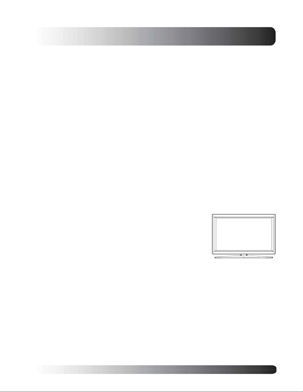
Flat Panel Monitor
Getting to Know
Your Display
7
Getting to Know Your Display
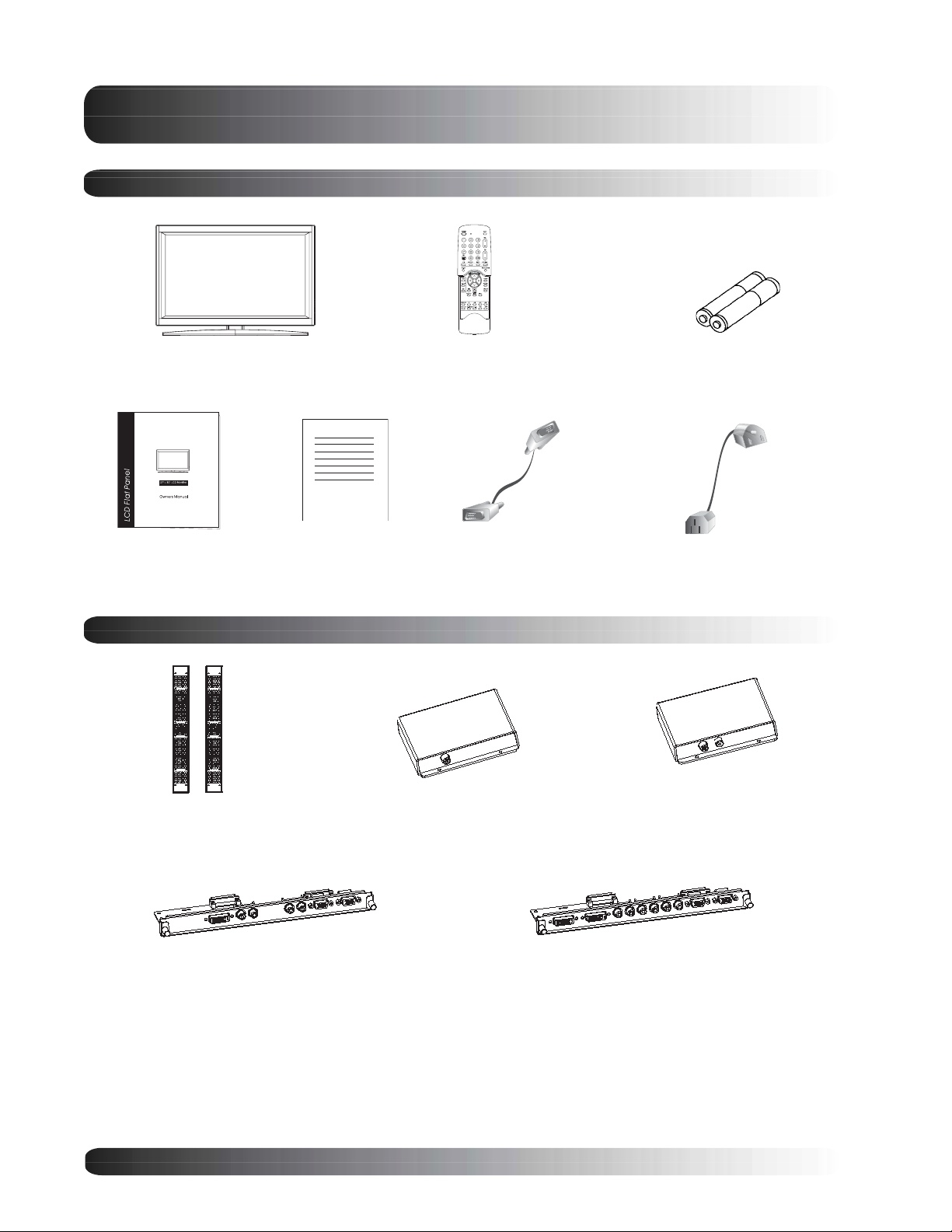
Package Contents
Flat Panel Display Remote Control
User Manual Warranty Card AC Power CordVGA Cable
Optional Accessories
Side-Mount Speakers
Single-TV Tuner Module
Batteries
Dual-TV Tuner Module
Single-DVI Port/RGB Module
Dual-DVI Port/RGB Module
8
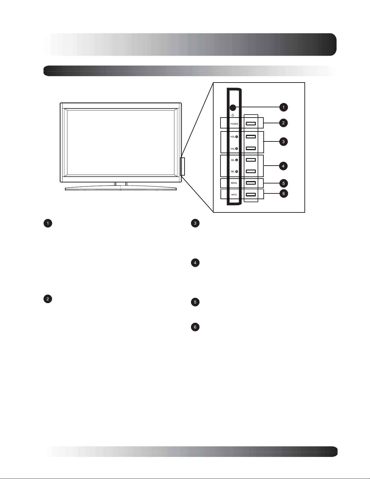
Front Panel Controls
Getting to Know Your Display
Status LED
Not Illuminated - No AC Power detected
If the main power switch (rear of panel) is turned off,
this LED will not illuminate.
Orange - Standby (Power OFF) with AC power
detected
The LED will illuminate in orange color if the monitor
is shut-off but the main power cord is plugged into
the back of the unit.
Solid Green - Power ON
Power (Standby) Button
Turns power on/off from standby mode. There is a
wait period between on/off cycles.
Volume Adjustment Buttons
Use these buttons to adjust volume up and down.
These keys also serve as navigation and adjustment keys when On Screen Display menu is
engaged.
Select Buttons
Use these buttons to navigate through the the On
Screen Display menu. If an optional TV tuner is
intalled, these buttons also function as Channel Up/
Down.
Menu Button
Use this button to engage the On Screen Display
menu.
Input Button
Use this button to switch between available inputs.
9
Getting to Know Your Display
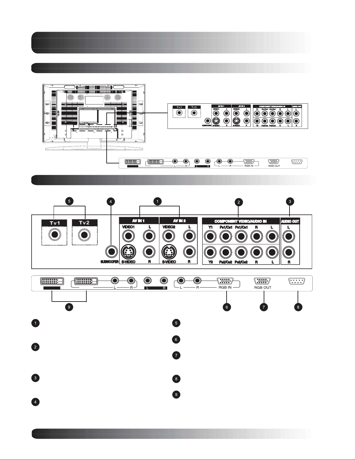
Rear Panel
Video Connectors
RGB/Computer Related Connector
DVI IN 2
DVI IN 1
Rear Panel Connections
DVI IN 2
Composite / S-Video Inputs
Connect Composite or S-Video signals from
external sources such VCRs or DVD players.
Component Video Inputs
Auto-detecting component video inputs (Y/Pb/Pr or
Y/Cb/Cr) for connecting to the component output
jacks of a DVD player or Set-Top Box.
Audio Output
Variable or fixed audio output jacks for connecting
to an external audio amplifier.
Subwoofer Output
Variable or fixed low-frequency audio output jack for
connecting to an external amplified subwoofer.
DVI IN 1
RS-232
RS-232
Antenna Jack (Optional)
Connect to TV or CATV antenna.
RGB Input (Optional)
Connect to RGB output of computer or Set-Top box.
RGB Output (Optional)
Connect to another computer monitor for daisy
chaining applications.
RS-232 Connector
Connect to a computer serial port.
Digital DVI Inputs (Optional)
Connects to the digital video signals
from a set top box or PC.
10

Getting to Know Your Display
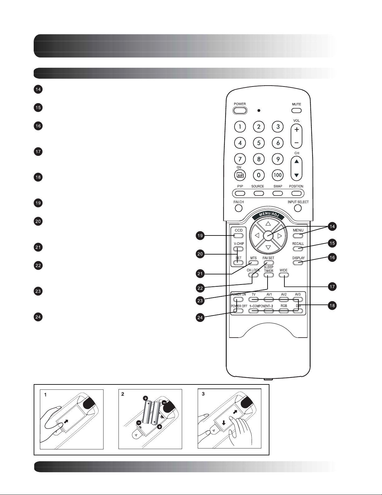
Remote Control
Standby Power On/Off
Push this button to turn on the monitor from Standby
mode. Push it again to turn off to Standby mode.
Number Keypad*
Use number keypad to select the TV channel you want to
watch.
QuickView*
Use QuickView key to recall the last TV channel watched.
(See Page 72)
PIP (Picture-in-Picture Button)
Turns on PIP (Picture-in-Picture) mode and POP (Side-by-
Side) picture mode. (See Page 36)
PIP/POP Source
Changes the input source of the PIP or POP sub-window.
(See Page 36)
Favorite Channel*
Recalls TV channels programmed using favorite channel
memory.
(See Page 71)
Sound Mute On/Off
Volume +/-
Turns volume up or down.
Channel UP/DOWN*
Change TV channels sequentially by pressing +/-.
Swap
This key swaps the main and sub picture windows under
PIP or POP modes. (See page 36)
PIP Position
This key changes the PIP sub-window to 4 different corner
locations. (See Page 36)
Input Select
Press to select input signal modes sequentially. (See
Page 26)
*Only applicable when TV tuner option(s) are installed
11
Getting to Know Your Display
Remote Control
Menu
Engages the OSD menu.
Recall
Recalls default picture settings. (See Page 34)
Display
Press to show the status of the monitor. (See Page
29)
WIDE
Toggles between various aspect ratio settings. (See
Page 30)
Direct Input Selection Keys
Directly change input signal selection by pressing the
appropriate key.
Closed Captioning*
Turns on Closed Caption Mode. (See Page 67)
V-Chip*
Engages V-Chip protection circuitry settings. (See
Page 68)
MTS Stereo*
Engages MTS stereo reception for TV. (See Page 66)
Channel Lock / Fav. Set*
Engages Channel Lock and Favorite Channel Setup
Menu. (See Page 71)
Sleep Timer
Engages Sleep Timer Settings.
(See Page 52)
Discrete Power ON/OFF
Press OFF to send monitor into Standby mode.
Press ON to power on from standby mode.
*Only applicable when optional TV tuner(s) are installed
Battery Installation
12

Flat Panel Monitor
Display
Connections
13

Display Connections
Connecting TV or CATV
Connecting to TV or Cable TV
Make sure your monitor is equipped with a TV tuner. You can tell by looking at the connection jacks located
on the back of the monitor. If there is a threaded-screw type of connector (called the RF connector), then you
have a TV tuner. If you do not see this type of connector, then you do not have a TV tuner installed.
Connect the RF cable from the antenna or
cable socket to the RF connector labeled as
TV1 or TV2 on the back of the monitor.
Notes:
! If your monitor is not equipped with a TV
tuner, please contact your local sales
representative for purchase.
! If there is only one antenna connector and
your monitor is equipped with two TV
tuners, you will need to use a antenna
signal splitter to connect to the two RF
connectors.
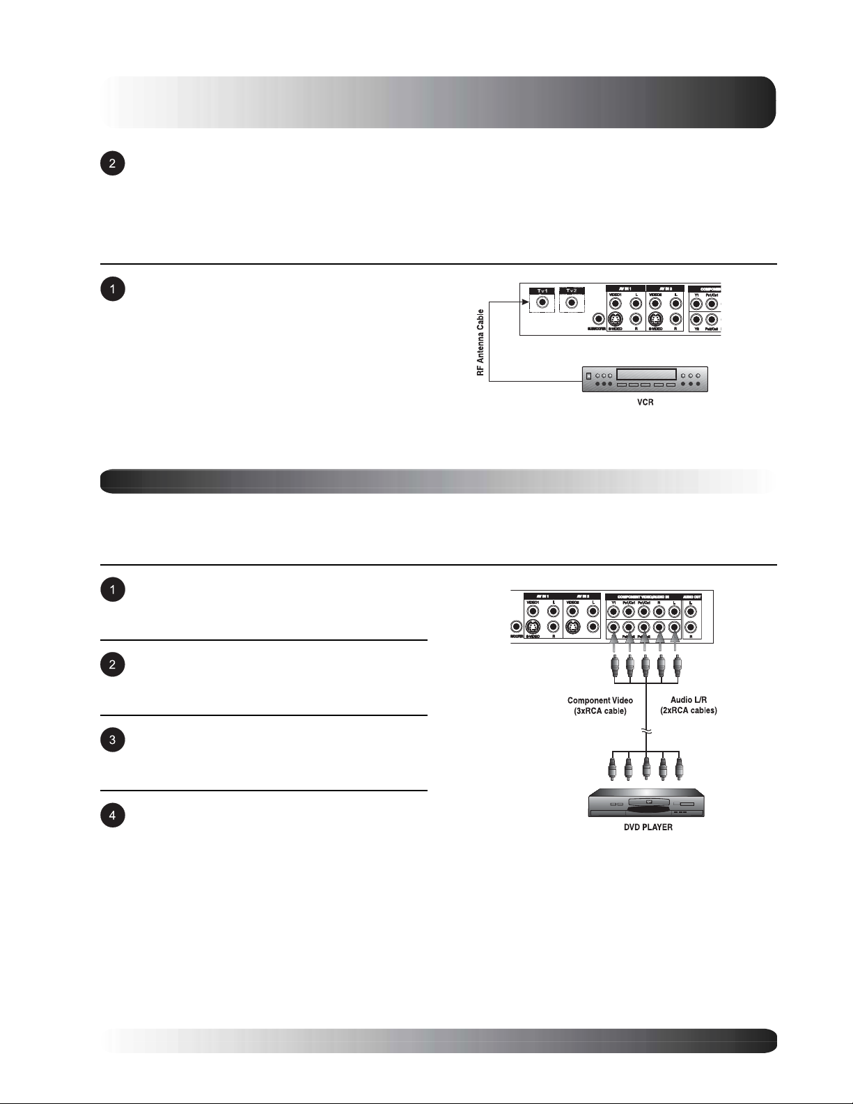
Connecting a VCR
Using S-Video Input
Connect the S-Video (4-pin DIN) connector from
the VCR to the S-Video input on the back of
monitor.
Connect the red (R) and white (L) audio jacks
from the VCR to the (R) and (L) audio-in jacks
located next to the S-Video connector.
Note:
! There are two sets of S-Video inputs
provided.
Using Composite Input
Connect the yellow (video) out connector from
the VCR to the yellow video input on the back of
monitor.
Note:
! There are two sets of composite inputs
provided.
14
Connect the red (R) and white (L) audio-out
jacks from the VCR to the R and L audio-in
jacks located next to the yellow Video
connector.
Using TV Input
Connect the output to TV (RF out or Antenna
out) connector from the VCR to the ANT input
on the back of monitor.
Notes:
! The TV input option is only available when a
TV tuner is installed.
! Cable must be connected from wall/cable
box into the VCRs antenna (RF) input.
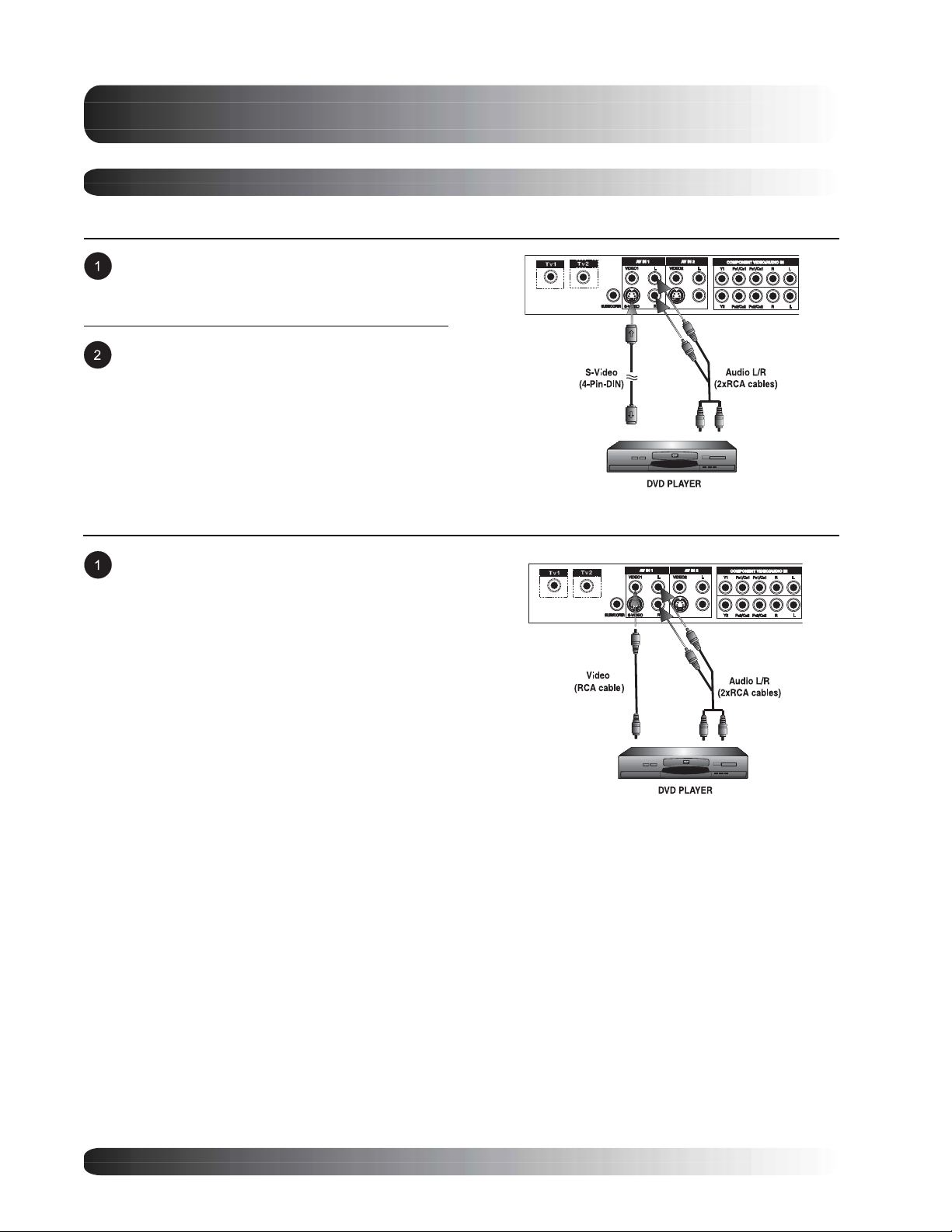
Connecting a DVD
Display Connections
Using Component Video Input
There are two sets of component video inputs provided. You can use either set of component inputs to connect
your DVD.
Connect the green-colored (labeled as Y) jack
from the DVD to the green-colored jack of the
monitor.
Connect the red-colored (labed as Pr or Cr) jack
from the DVD to the red-colored Pr1/Cr1 jack of
the monitor.
Connect the blue-colored (labed as Pb or Cb)
jack from the DVD to the blue-colored Pb1/Cb1
jack of the monitor.
Connect the red (R) and white (L) audio jacks
from the DVD to the R and L audio-in jacks
located next to the Pr/Cr1 connector.
15
Display Connections
Connecting a DVD (con’t)
Using S-Video Input
Connect the S-Video (4-pin DIN) connector from
the DVD to the S-Video input on the back of
monitor.
Connect the red (R) and white (L) audio jacks
from the DVD to the (R) and (L) audio-in jacks
located next to the S-Video connector.
Note:
! There are two sets of S-Video inputs
provided.
Using Composite Input
Connect the yellow (video) out connector from
the DVD to the yellow video input on the back of
monitor.
Note:
! There are two sets of composite inputs
provided.
16
Display Connections
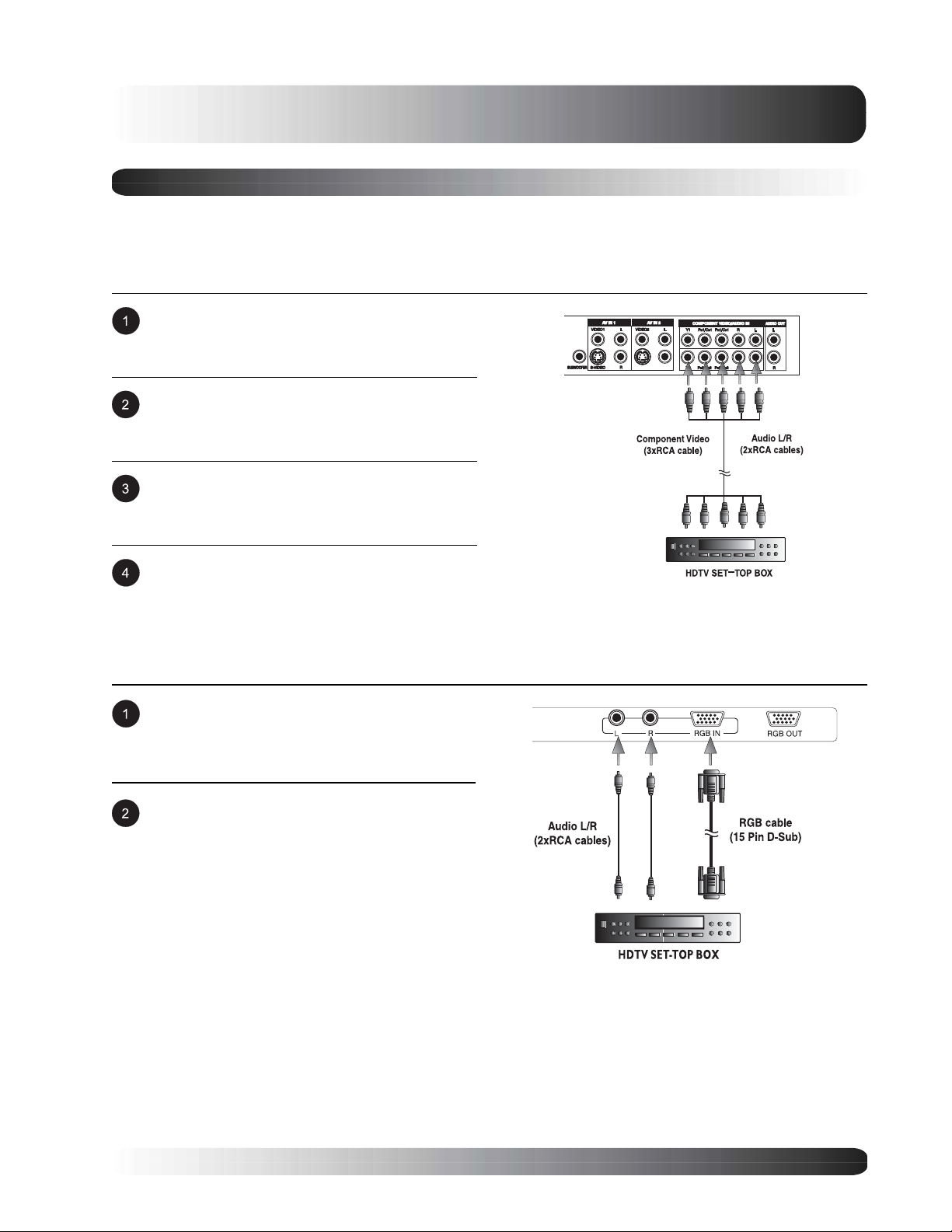
Connecting a Set-Top Box
Using Component Video Input
There are two sets of component video inputs provided. You can use either set of component inputs to connect
your STB. Some HDTV Set top boxes may not have a Component Video output. Instead, use RGB or DVI
input method.
Connect the green-colored (labeled as Y) jack
from the STB to the green-colored jack of the
monitor.
Connect the red-colored (labed as Pr or Cr) jack
from the STB to the red-colored Pr1/Cr1 jack of
the monitor.
Connect the blue-colored (labed as Pb or Cb)
jack from the STB to the blue-colored Pb1/Cb1
jack of the monitor.
Connect the red (R) and white (L) audio jacks
from the STB to the R and L audio-in jacks
located next to the Pr/Cr1 connector.
Using RGB Input
Connect the 15-pin D-Sub RGB connector from
the back of the HDTV set top box to the RGBIN Connector located on the back of the
monitor.
Connect the red (R) and white (L) audio-out
jacks from the HDTV set top box to the R and L
audio-in jacks located next to the RGB
connector.
Notes:
! Some HDTV Set top boxes may not have a RGB output. Use Component Video input or DVI input
method if this is the case.
! Upon connecting your HDTV set top box to the RGB input of the monitor, it may be necessary to
adjust various picture settings on the monitor to correctly match the output of the HDTV set top box.
This is caused by the different video timings set by various HDTV set top box manufacturers. (See
Page 42 for more information).
! RGB input may not be available on your display as this is an optional accessory. Please contact
your local sales representative for purchase information.
17
Display Connections
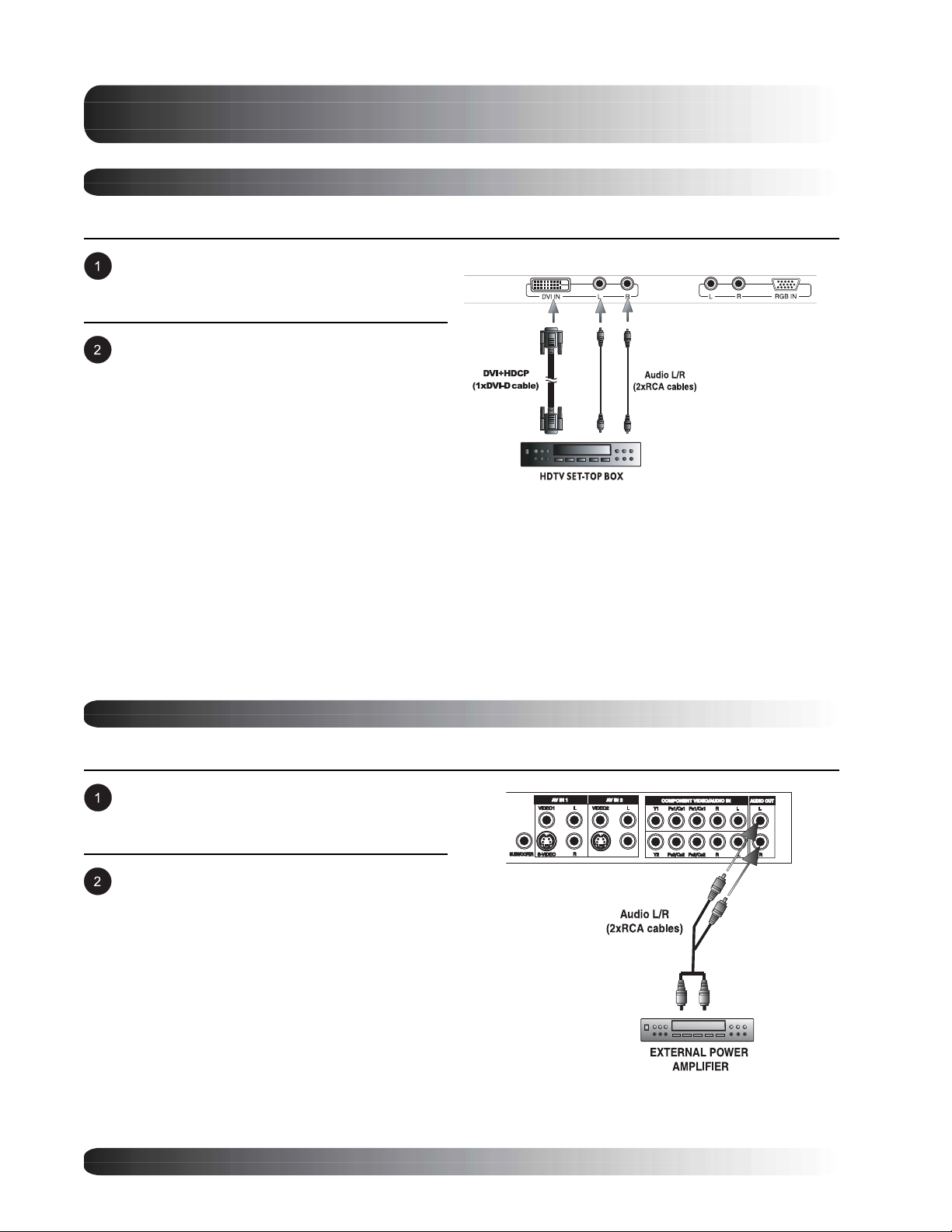
Connecting a Set-Top Box (con’t)
Using DVI Input
Connect the DVI-D connector from the back of
the HDTV set top box to the DVI-IN Connector
located on the back of the monitor.
Connect the red (R) and white (L) audio-out
jacks from the HDTV set top box to the R and L
audio-in jacks located next to the DVI-D
connector.
Notes:
! Some HDTV Set top boxes may not have a DVI output. Use Component Video input or RGB input
method if this is the case.
! Upon connecting your HDTV set top box to the DVI input of the monitor, it may be necessary to
adjust various picture settings on the monitor to correctly match the output of the HDTV set top box.
This is caused by the different video timings set by various HDTV set top box manufacturers. (See
Page 42 for more information).
! DVI input may not be available on your display as this is an optional accessory. Please contact your
local sales representative for purchase information.
External Audio Connections
Connecting to an External Amplifiers
This monitor can be connected to an external
amplifier using the AUDIO OUT jacks located
on the back of the monitor.
Connect the red (R) and white (L) AUDIO OUT
jacks from right side of the connector panel to
the external amplifier.
Note:
! The AUDIO OUT RCA jacks can be set to
either Fixed or Variable audio output levels.
(See Page 50 for more information)
18
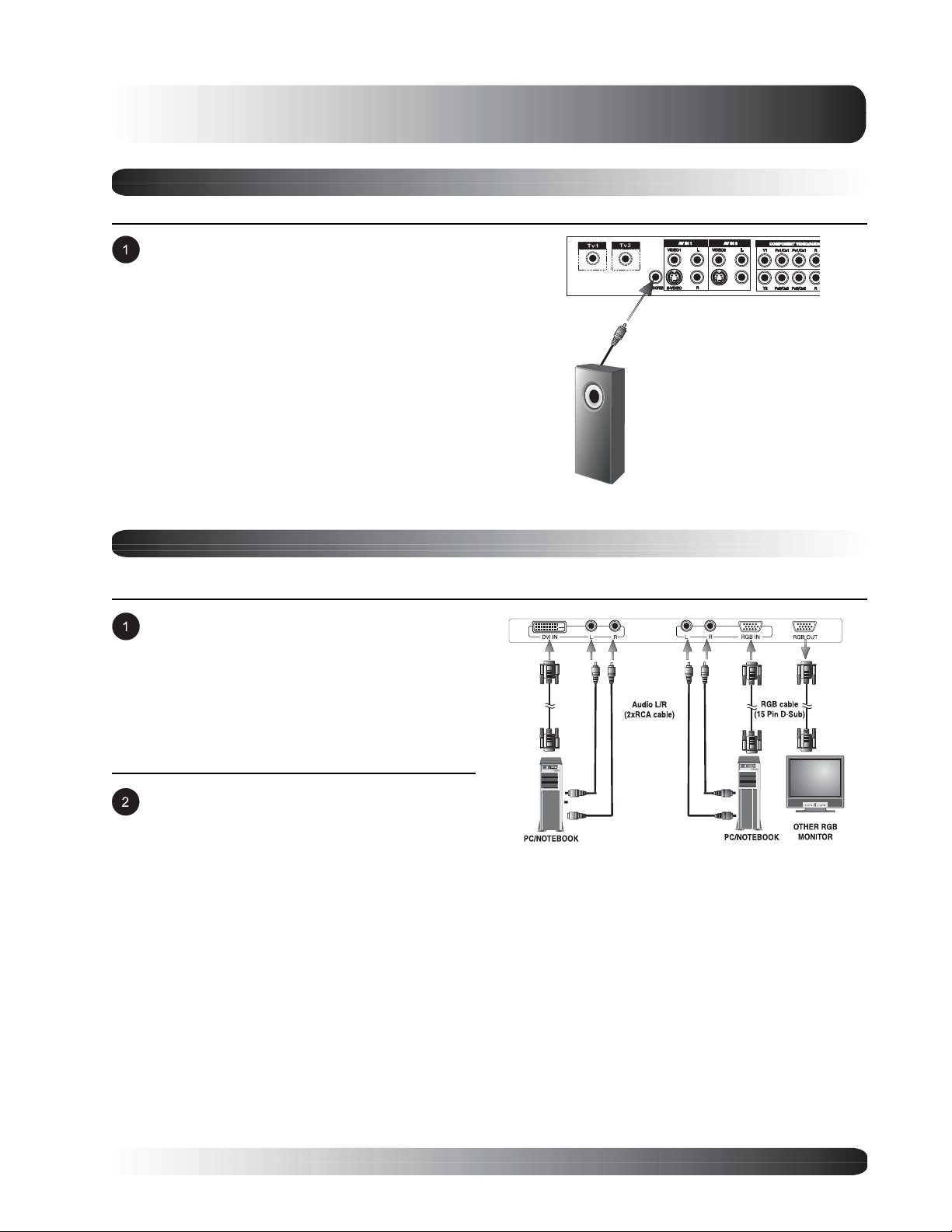
Display Connections
Connecting a Subwoofer
This monitor is equipped with a subwoofer output for connecting to an external amplified subwoofer.
Connect a RCA cable from the subwoofer’s
input to the subwoofer’s output jack on the
back of the monitor.
Notes:
! The RCA subwoofer outputs frequencies
below 120Hz.
! The subwoofer output jack is governed by
FIXED or VARIABLE audio output setting
and works in conjunction with AUDIO OUT
jacks.
Connecting a PC
Using RGB or DVI Video Input
For most PCs, connect the 15-pin D-Sub RGB
connector from the back of the PC to the RGBIN Connector located on the back of the
monitor. If you have a PC that is equipped with
a DVI (Digital Visual Interface), you may
connect the PC DVI connector from the back of
the PC to the DVI-In Connector located on the
back of the monitor.
Connect the red (R) and white (L) audio jacks
from the PC to the R and L jacks located next
to the RGB connector. If you are using a DVI
interface, simply connect the (R) and (L) audio
jacks to the R and L jacks located next to the
DVI connector.
Note:
! A RGB loop-out labeled RGB Out will allow another RGB monitor to be connected. The RGB loop-out
will display the same signal as the RGB In signal source.
19
Display Connections
Connecting a PC (con’t)
Setting Up Your Monitor Using Plug and Play
This monitor adheres to VESA Plug and Play standard to eliminate complicated and time consuming setup of
monitors. This monitor identifies itself to the computer and automatically sends the PC its Extended Display
Identification Data (EDID) using Display Data Channel (DDC) protocols.
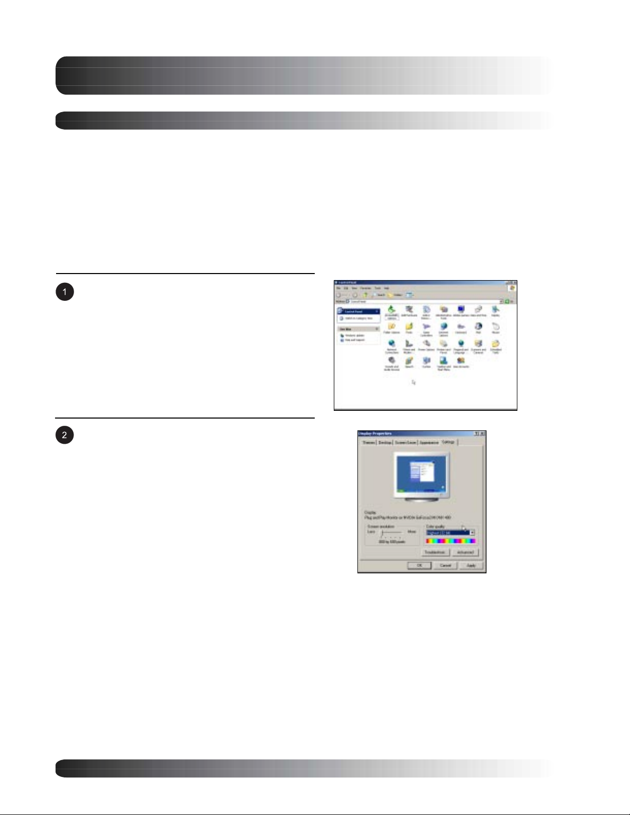
How to Set up Your PC for Use with Monitor (Windows)
The display settings for a typical Windows-based computer are shown below; however, actual screens on your
computer will differ depending on the version of Windows and video card equipped with the computer. Even
though the actual screen may look different from example displayed below, basic set-up routine will apply in
most cases.
Go to Window’s CONTROL PANEL by clicking:
START, SETTINGS, CONTROL PANEL. The
CONTROL PANEL Window is displayed. Select
the DISPLAY icon from this window.
The DISPLAY PROPERTIES dialog box is
displayed. Select the SETTINGS tab to display
your computer’s video output settings.
Set the “Screen Resolution” settings to 640x480
PIXELS. For COLOR QUALITY, select 24 BIT
COLOR (might also be expressed as 16 million
colors).
If a vertical-frequency option exists, set the value to
60 or 60 Hz.
Click OK to complete the setting.
Note:
! Both screen position and size will vary, depending on the type of PC graphics card and its resolution
selected. To adjust position and size, refer to Page 42.
20

Connecting a PC (con’t)
Supported Resolutions
This monitor supports the following resolutions
Vertical Horizontal
Frequency Frequency Dot Rate Vertical Horizontal
Dot x Line (KHz) (KHz) (MHz) Polarity Polarity
640 x 480@60Hz 31.469 59.940 25.175 - -
640 x 480@72Hz 37.861 72.809 31.500 - -
640 x 480@75Hz 37.500 75.000 31.500 - -
640 x 480@85Hz 43.269 85.008 36.000 - -
800 x 600@56Hz 35.156 56.250 36.000 + +
800 x 600@60Hz 37.879 60.317 40.000 + +
800 x 600@72Hz 48.077 72.188 50.000 + +
800 x 600@75Hz 46.875 75.000 49.500 + +
800 x 600@85Hz 53.674 85.061 56.250 + +
1024 x 768@60Hz 48.363 60.004 65.000 - -
1024 x 768@70Hz 56.476 70.069 75.000 - -
1024 x 768@75Hz 60.023 75.029 78.750 + +
1024 x 768@85Hz 68.677 84.977 94.500 + +
1280 x 960@60Hz 60.000 60.000 108.000 + +
1280 x 1024@60Hz 63.981 60.020 108.000 + +
1280 x 1024@75Hz 79.976 75.025 135.000 + +
640 x 350@70Hz 31.469 70.087 25.175 - +
640 x 480@50Hz 31.469 50.030 25.175 - -
640 x 480@67Hz 35.000 66.667 30.240 - -
720 x 400@70Hz 31.469 70.087 28.322 + -
848 x 480@60Hz 29.640 60.000 29.875 - +
832 x 624@75Hz 49.725 74.551 57.283 - -
1360 x 768@60Hz 47.368 59.960 72.000 - +
1280 x 720p@60Hz 45.000 60.000 74.250 + +
1920 x 1080i@60Hz 33.750 60.000 74.250 + +
1280 x 720@60Hz 44.760 60.000 74.481 - -
1280 x 768@60Hz 47.700 60.000 80.136 - -
1366 x 768@60Hz 47.700 60.000 85.383 - -
1152 x 870@75Hz 68.681 75.062 100.000 - -
Display Connections
Note:
! Resolution 1280 x 720@60Hz is for 27” LCD only and 1280 x 768@60Hz is for 30” LCD only.
21
Display Connections
RS-232 Connection
Overview
This monitor is equipped with an RS-232 serial terminal for using the monitor with computer controls. The
RS-232 serial terminal conforms to the RS-232C interface specification. The computer will require software
application (such as HyperTerminal) which allows the computer to send and receive control data that can
support the communication parameters described in this section.
Interface Parameters
These parameters are required to setup communications with the monitor.
Specification RS-232C
Sync Method Synchronous
Baud Rate 9600 bps
Parity None
Character Length 8 Bits
Stop Bit 1 Bits
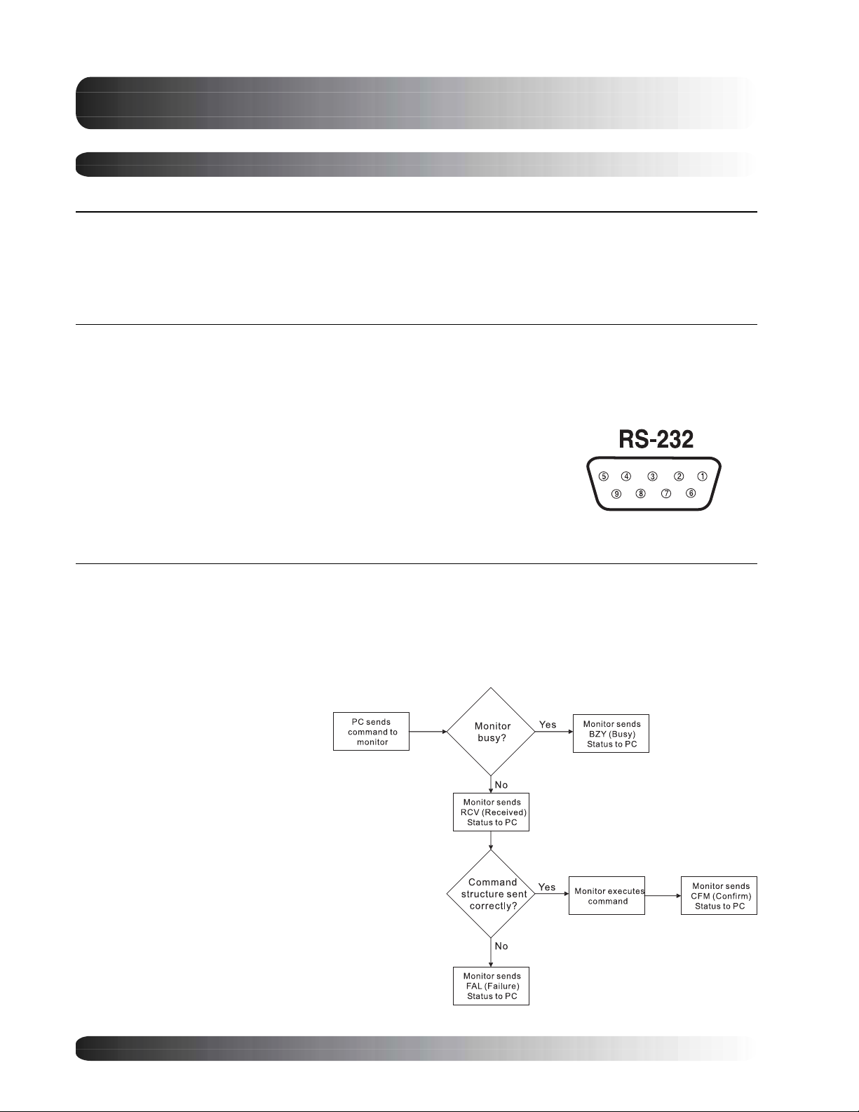
RS-232C Pint Layout
Pin 1 Received Line Signal Detector (Data Carrier Detect)
Pin 2 Received Data (RXD)
Pin 3 Transmit Data (TXD)
Pin 4 Data Terminal Ready (DTR)
Pin 5 Signal Ground
Pin 6 Data Set Ready (DSR)
Pin 7 Request To Send (RTS)
Pin 8 Clear To Send (CTS)
Pin 9 Ring Indicator
Command Format and Sequencing
Data Structure Overview
In order to transmit data from the computer to the monitor, the data must be sent in a structured format. The
format used by this monitor follows a COMMAND:DATA sequence. All commands and its related data are
formatted using a 3-character format separated by a colon in-between. For example, the Power On command
is sent as: PWR:PON where PWR is telling the monitor that it is receiving a Power related command, followed
by the actual command to carry out.
Communications Overview
As commands are sent from the PC,
the monitor will provide feedback
regarding the state of command
execution back to the PC. The monitor
provides information status to inform:
1. Whether the command sent by
the computer was received by
the monitor.
2. Whether the COMMAND:DATA
structure was correctly
formatted for execution by the
monitor.
3. Whether the command sent
was successfully carried out by
the monitor.
22
Display Connections
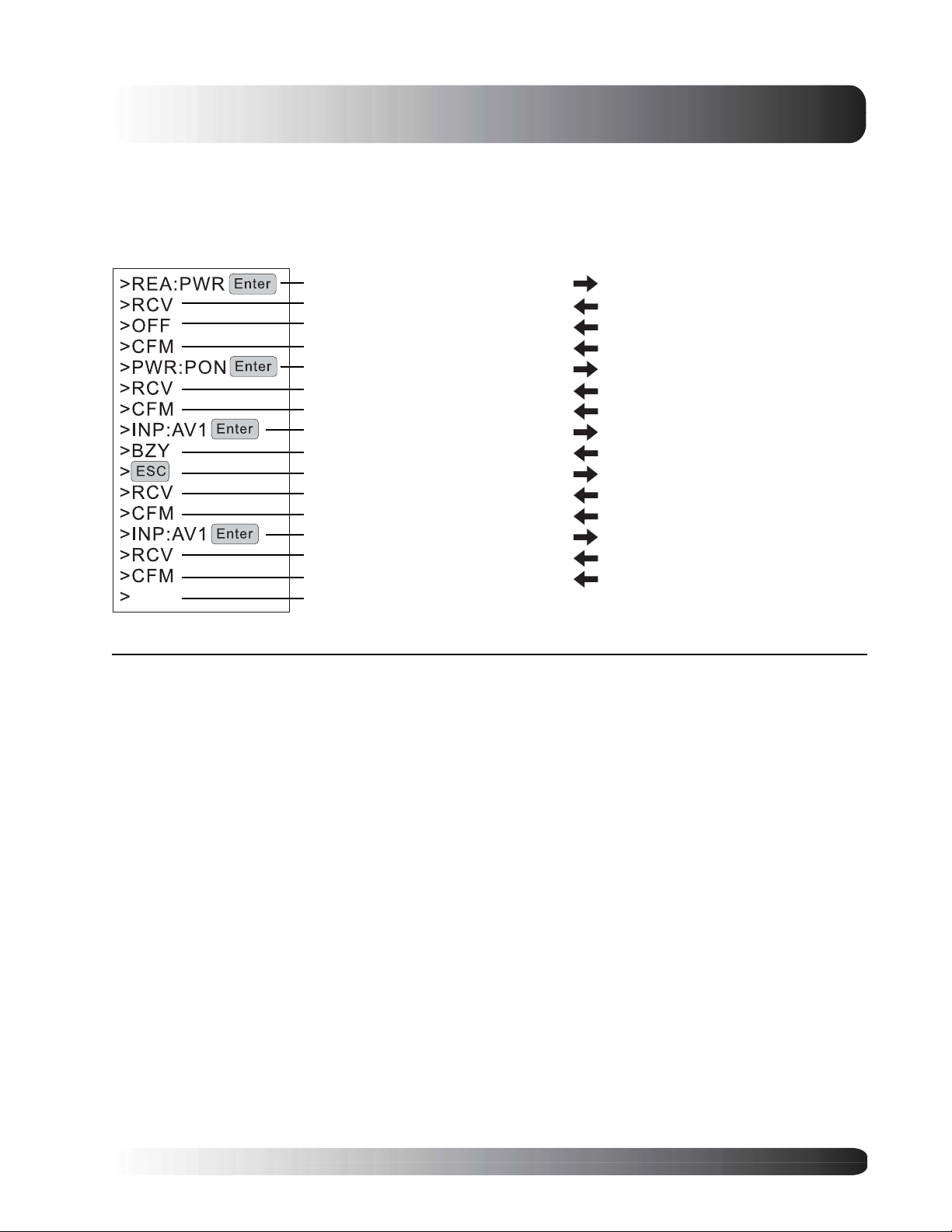
The following is an example of the communication process between the PC and the monitor using a program
such as HyperTerminal.
Example: Read Power Status followed by Power On command and input select to AV1 with disruption
PC Status Monitor Status
Send command to read power status Monitor rcv’s command
Rcv acknowledgment of command received
Rcv OFF status from monitor
Send command to POWER ON the monitor Monitor is not busy and waiting for command
Send command to switch to AV1 input
Rcv acknowledge of command not accepted
Send command to void previous command Rcv’s command to clear previous command
Rcv acknowledgment of command received
Send command to switch to AV1 input again Monitor is not busy and rcv’s command
Rcv confirmation of command complete
Sends confirmation of command rcv’d to PC
Sends actual status of power to PC (OFF)
Sends confirmation of command completionRcv confirmation of command complete
Sends confirmation of command rcv’d to PCRcv acknowledgment of command
Monitor powers on and sends confirmationRcv confirmation of command complete
Monitor is busy doing another task
Sends busy status because it can’t rcv data
Sends confirmation of command rcv’d to PC
Clears command buffer and sends confirmRcv confirmation of command complete
Sends confirmation of command rcv’d to PCRcv acknowledgment of command received
Monitor switches to AV1 and sends confirm
Monitor is ready to accept another commandReady to send another command
Command and Data Tables
Description Command Data Options
Read Data REA VOL, PWR, BRT, CON, CLR, TNT, SHP, INP, VSZ, VPS, HSZ, HPS, RCL, SAV, MUT,
LNG,
PIS,
Volume VOL 001…100
Power On/Off PWR PON=Power On, OFF=Power off
Brightness BRT 001…100
Contrast CON 001…100
Color CLR 001…100
Tint TNT 001…100
Sharpness SHP 001…100
Input Select INP TV1=Tuner1, TV2=Tuner2, AV1=AV Input 1, AV2=AV Input 2, CP1=Component Input 1,
V-Size VSZ 001…100
V-Position VPS 001…100
H-Size HSZ 001…100
H-Position HPS 001…100
Recall RCL 000
Save SAV 000
Mute MUT MON=On, OFF=Off
Language LNG ENG=English, SPA=Spanish, FFR=French
Color Temp TMP LOW=Low, MID=Middle, HIG=High, 65D=6500D, CUS=Custom
Bass BAS 001…100
Treble TRB 001…100
Balance BAL 001…100
BBE BBE BON=BBE On, OFF=BBE Off
Surround Sound SRS OFF=Off, STR=Stereo, MON=Mono
Tuner 1 Source TS1 AIR=Air, CBL=Cable
Tuner 2 Source TS2 AIR=Air, CBL=Cable
Channel Search CSR TV1=Channel Search TV1, TV2=Channel Search TV2
TMP, BAS, TRB, BAL, BBE, SRS, TS1, TS2, CSR, TV1, TV2, CCD, ZOM, PIP, POP
POF, SIN, SWP, RGN, GGN, BGN, RBS, GBS, BBS, FPL, ILO, IUL, STS, BI1, BI2, BI3
CP2=Component Input 2, RG1=RGB1, RG2=RGB2, DV1=DVI1, DV2=DVI2
23

Display Connections
Description Command Data Options
TV1 Channel Change TV1 001…125
TV2 Channel Change TV2 001…125
Closed Captioning CCD OFF, CC1, CC2, CC3, CC4, TX1, TX2, TX3, TX4
Zoom ZOM WID=16:9, PAN=Panorama Stretch, NOR=4:3 with black bars, ZO1=Zoom1,
PIP PIP PON=PIP On, OFF=PIP Off
POP POP PON=POP On, OFF=POP Off
PIP Position PIS PS1=Position 1, PS2=Position 2, PS3=Position 3, PS4=Position 4
POP Format POF PF1=Full size, PF2=16:9 Format, PF3=4:3 Format
Sub-Source SIN TV1=Tuner 1, TV2=Tuner 2, AV1=AV Input 1, AV2=AV Input 2,
Sub-Swap SWP 000
R-Gain RGN 001…256
G-Gain GGN 001…256
B-Gain BGN 001…256
R-Bias RBS 001…256
G-Bias GBS 001…256
B-Bias BBS 001…256
Clear Buffer Escape Key Simply press the ESC key on the keyboard will send command to clear command buffer
ZO2=Zoom2, ZO3=Zoom3
CP1=Component Input 1, CP2=Component Input 2, RG1=RGB1, RG2=RGB2,
DV1=DVI1, DV2=DVI2
24

Flat Panel Monitor
Basic
Operations
25
Basic Operations
Powering On/Off
Using Front Panel or Remote Control
Make sure the monitor is plugged into the wall outlet and the main AC switch located on the rear of the monitor
is switched to ON position. If the power is plugged in and the AC switch is on, the STATUS LED will illuminate
in orange color.
Press the key on the panel or the remote
control.
The monitor will now turn on after a brief pause.
The STATUS LED will now turn green to
indicate power on status.
To turn power off, simply press the key on
the panel or the remote control once again.
POWER (Toggle)
Using Discrete Power ON/OFF Keys
The discrete POWER ON/OFF keys send two discrete signals to the monitor, one for ON and one for OFF.
Because signals are discrete, these keys can be used by third-party universal remote controls for macro
programming.
To turn power on, simply press the
button. If the monitor is turned on already,
pressing this button will have no effect.
To turn off power, simply press the
button. If the monitor is already turned off,
pressing this button will have no effect.
Discrete
POWER ON/OFF
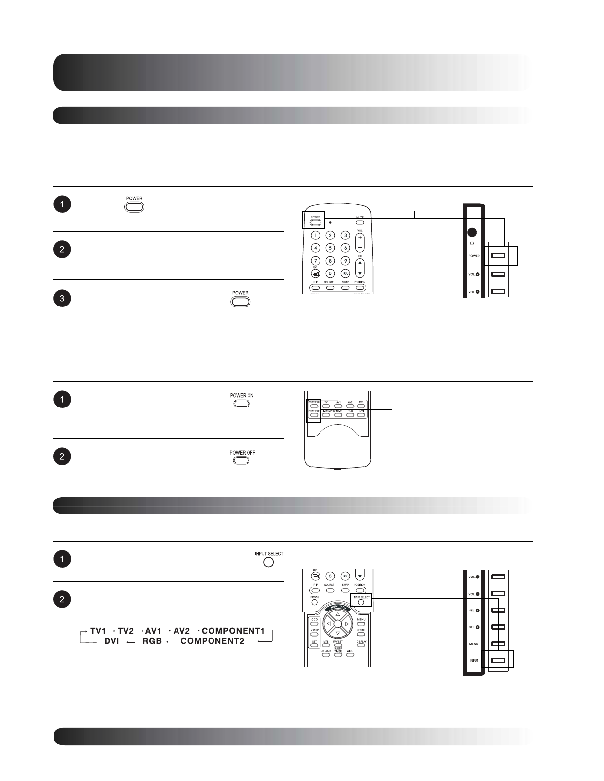
Changing Inputs
Using Front Panel or Remote Control
Press the INPUT key on the panel or the
key on the remote control.
Pressing the INPUT key will cycle the monitor
through all available input signal sources in the
following order:
Notes:
! If TV tuner is not installed, TV option will
not be available.
! If optional dual-port DVI / RGB module is
installed, DVI2 will be available.
26
Input Select
(Toggle)
Basic Operations
Using Direct Input Selection Keys
If you prefer not to cycle thru all available inputs, you can use the Direct Input Selection keys located towards
the bottom of the remote control.
Simply select the input that you would like to
switch to and press the Direct Input Selection
key for that input.
Note:
! TV2 and DVI2 direct input keys are not
available.
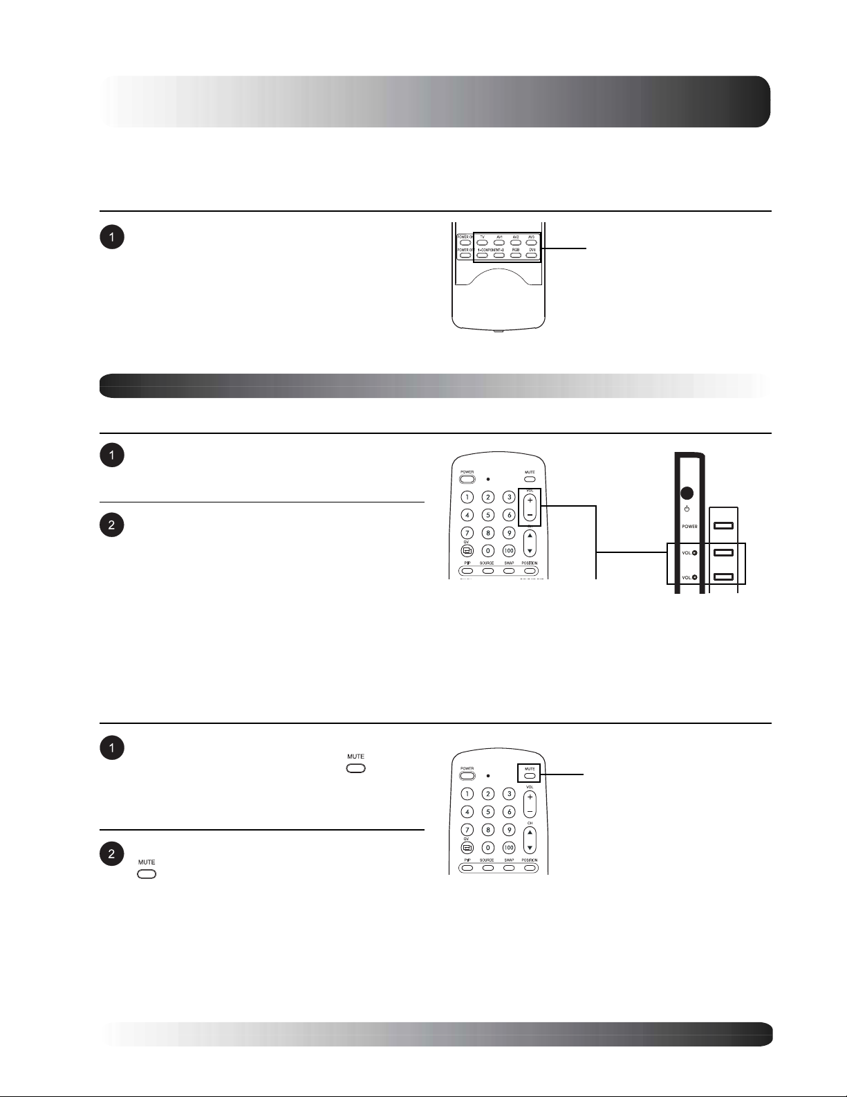
Volume Adjustment
Using Front Panel or Remote Control
To turn up sound volume, press VOLUME + on
either the front panel of monitor or on the
remote control.
Direct Input
Selection Keys
To turn down sound volume, press VOLUME on either the front panel of monitor or on the
remote control.
Note:
! If the monitor’s built-in speakers are turned
off, then volume controls will not affect
volume generated by the built-in speaker.
Using MUTE
If you would like to silence the volume on a
temporary basis, simply press the key to
silence the volume. When the monitors volume
is muted, the monitor will display MUTE on the
upper right corner of the screen.
To disengage the mute mode, simply press the
key again or the volume buttons.
Note:
! If the monitor’s built-in speakers are turned
off, then volume controls will not affect
volume generated by the built-in speaker.
VOLUME +/-
MUTE
27
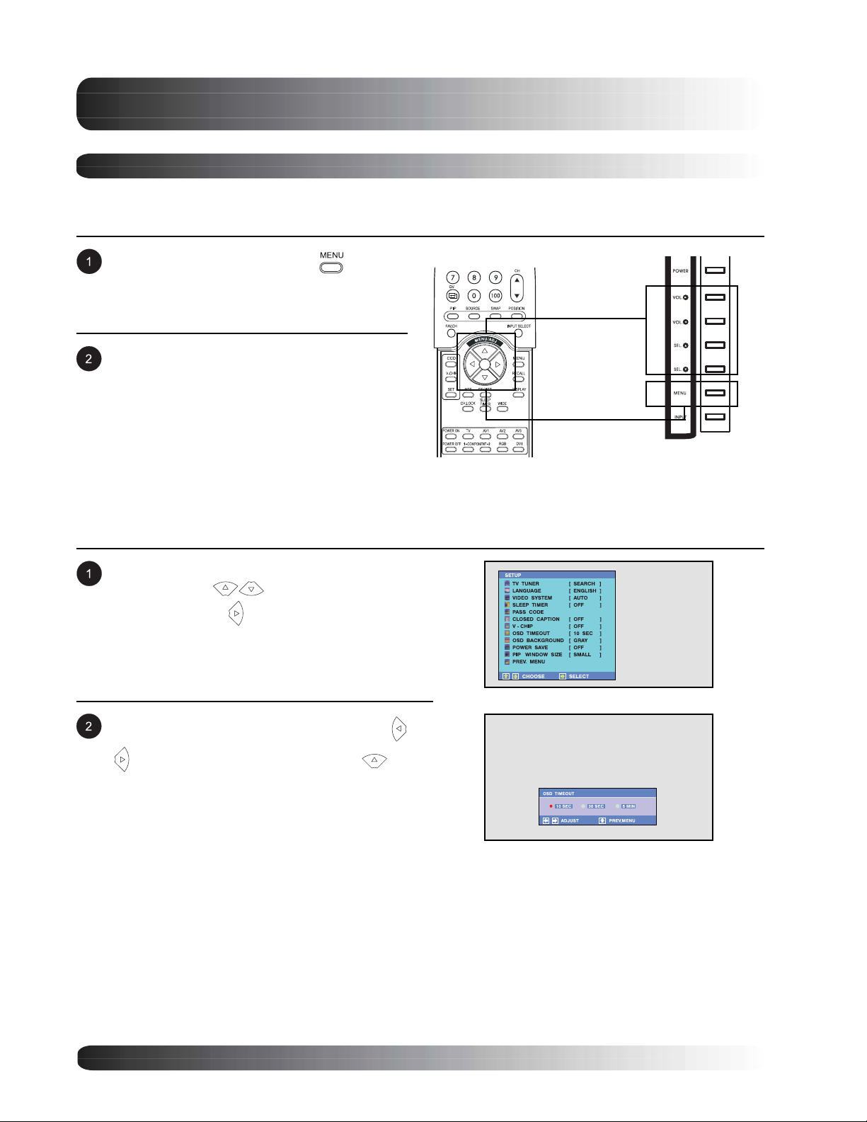
Basic Operations
On-Screen Display Menu
Accessing OSD Menu via Remote Control or Front Panel
The On-Screen Display (OSD) menu allows access to setup various parameters equipped with this display.
To access the OSD menu, press
the front panel of monitor or press any one of
the four arrow keys located on the remote
control.
Navigation through the OSD Menu can be
accomplished using the arrow keys on the
remote control or using the front panel control
keys.
button on
OSD Menu
Navigation
OSD Menu
Access
OSD Menu Timeout Setting
OSD Menu will automatically dissappear after a preset period of time so that it doesn’t remain on the screen. To
change the OSD timeout period, please follow the steps below.
Access the OSD menu, select SETUP
submenu. Use keys to highlight OSD
TIMEOUT. Press key to confirm selection.
The OSD Timeout window is displayed. Use
keys to adjust your settings. Press
key to confirm selection.
28
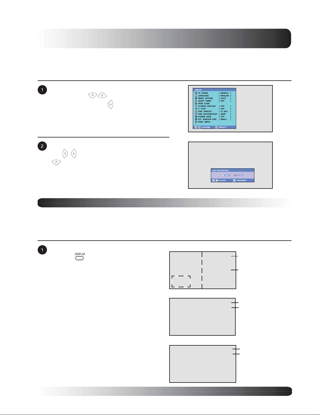
Basic Operations
OSD Background Color Setting
The background color of the OSD Menu can be customized. To change the OSD Background color setting,
please follow the steps below.
Access the OSD menu, select SETUP
submenu. Use keys to highlight OSD
BACKGROUND. Press
selection.
The OSD BACKGROUND window is displayed.
Use keys to adjust your settings. Press
key to confirm selection.
key to confirm
On-Screen Status Display
Displaying Status
The On-Screen Status Display shows detailed information regarding the operational status of the monitor. The
status display automatically appears whenever there is a change in the state of the monitor such as channel
change or input change. The status display will automatically disappear after a timeout period.
To manually show the Status Display, simply
press the key on the remote control.
AV Mode
AV1
Input Source
Note:
! When using AV1 and AV2, priority is given
to the S-Video input.
! When using S-video connection AV1 and
AV2, the status display will denote “[S]” to
indicate the input source is using S-Video
connector.
PIP
Component Mode
COMPONENT1
RGB/DVI Mode
AV2
1080i
RGB
640x480
PIP/POP Source
Input Source
Signal Format
Input Source
Signal Format
29
 Loading...