

Maxent 42, 50 Owner's Manual

Plasma Flat Panel
42”/50” Plasma TV
Owner’s Manual
Important Safety Instructions
EN
WARNING
RISK OF ELECTRIC SHOCK
DO NOT OPEN
WAR NING: T o reduce the ris k of ele ctric shock, do not remove the front or back covers.
No user-serviceable parts inside. Refer servicing to qualified service personnel only.
2
The lightning flash with arrow-head
within a triangle is intended to inform
the user that parts inside the product
are a risk of electric shock.
The exclamation point within a triangle
is intended to tell the user that important
operating and servicing instructions are
explained.
Special Notices
Certain programs may be copyrighted a nd any unauthorized recording in whole or in part may be in violation
of copyright laws in the U.S. and Ca n ada.
FCC/CSA regulations state that any unauthorized modifications to this display may void user authority to
operate it.
Warnings & Precautions
To prevent damage which may result in fire or shock hazard, do not expose this product to rain or moisture.
To prevent electric shock, do not remove cover. No user serviceable parts are in side. Refer servicing to
qualified service personnel only.
Keep display away from excessive dust, high temperature, moisture or direct sunlight.
Use in a well-ventilated area and do not cover ventilation openings.
Unauthorized modifications to this equipment or usage of an unshielded connecting cable may cause
excessive interference.
When the display is not in use, disconnect it from the electric outlet.
If the picture displayed is in any way abnormal, turn off the unit and disconnect it from the electric outlet.
Verify your signal wire connections and reconnect the display to the electric outlet.
Do not place this product on an unstable cart, stand or table. The product may fall, causing serious
damage.
Do not place the unit on a bed, sofa, rug, or other similar surfaces.
Never place the unit near or over a radiator or heat source.
Do not install unit in an enclosed area unless proper ventilation is provided.
The unit should be operated from the type of power source indicated on the label. If the type of available
power is unknown, consult your dealer or local power company.
The unit is equipped with a 3-pin grounded plug. The plug will only fit into a grounded power outlet. This is a
safety feature. If you are unable to insert the plug into the outlet, contact your electrician. Do not alter this
plug as this will defe at the safety fe ature. Power cord not lighter tha n H05VV-F, 3G, 0.75mm2 shall be used.
Do not rest objects on the power cord & avoid pla cing power cord near high traf fic areas.
Do not overload wall outlets and extension cords as this can result in a risk of fire or electric shock.
Unplug the display from the electric outlet and disconnect the antenna/cable TV system during a lightning
storm or when left unused for long periods of time. This will prevent damage to the display caused by
lightning and power-line surges.
Avoid overhead power lines. An outdoor antenna system should not be placed in the vicinity of overhead
power lines, electric lights, or power circuits. When installing an outdoor antenna, be careful to not touch
any power lines or circuits as contact with these lines can be fatal.
Do not insert any foreign objects through the ventilation openings to the display. It may
touch dangerous voltage points or damage parts.
2

Importa nt Safety Instructions
If an outdoor a ntenn a or cable system is connected to the display , be sure the antenna or cable system is
grounded to provide some protection against voltage surges a nd static charge buildups. Section 810 of the
National Electrical Code, ANSI/NFPA No.70-1984, provides inf ormation about proper grounding of the ma st
and supporting structure, grounding of the lead-in wire to an antenna discharge unit, size of grounding
conductors, location of antenna discharge unit, connection to grounding electrodes, and requirements for the
grounding electrode.
If this display is equipped with separate speakers, please re move the speakers prior to moving the display.
Moving the display with the speakers attached may cause damage or injury.
Disconnect the unit from the main supply and refer servicing to qualified service personnel under the follow-
ing conditions:
- Power cord or plug is damaged or frayed.
- Liquid has been spilled into the product and/or the unit has been exposed to water or moisture.
- Unit does not operate normally when the operating instructions are not followed. Adjust only those
controls that are covered by the operating instructions, improper adjustment of other controls may result
in damage which often requires extensive work by a qualified technician to restore the unit to normal
operation.
- Unit has been dropped or the cabinet has been damaged.
- Unit exhibits a distinct change in performance, indicating a need for service.
Cleaning & Maintenance
EN
3
Disconnect from the electric outlet before cleaning. Do not use liquid or aerosol cleaners. Use only a slightly
damp cloth for cleaning.
Special Warranty Information
Cell Defects
Although the display panels are produced with more than 99% percent active cells, there may be some cells
that do not produce light or remain lit. This is considered normal and not a manufacturer defect.
Note to CATV System Installer-This reminder is provided to call the CATV system install’s attention to
Section 820-93 of the National Electric Code which provide guidelines for proper grounding and in
particular, specify that the Coaxial cable shield shall be connected to the grounding system of the
building, as close to the point of cable entry as practical.
3

EN
Regulatory Notice
FCC Statement
The Federal Communications Commission Radio Frequency Interference Statement includes the following
warning:
This equipment has been tested and found to comply with the limits for a Class B digital device, pursuant to Part
15 of the FCC Rules. These limits are designed to provide reasonable protection against harmful interference in
a residential installation. This equipment generates, uses, and can radiate radio frequency energy and, if not
installed and used in accordance with the instructions, may cause harmful interference to radio
communications. However, there is no guarantee that interference will not occur in a particular installation.
4
If this equipment does cause harmful interference to radio or television receptions, which can be determined by
turning the equipment off and on, the user is encouraged to try to correct the interference by one or more of the
following measures:
- Reorient or relocate the receiving antenna.
- Increase the separation between the equipment and receiver.
- Connect the equipment into an outlet on a circuit different from that to which the receiver is connected.
- Consult the dealer or an experienced radio/TV technician for help.
Warning
User must use shielded signal interface cables to maintain FCC compliance for the product. Provided with this
display is a detachable power supply cord with IEC320 style terminations. It may be suitable for connection to
any UL Listed personal computer with similar configuration. Before making the connection, make sure the
voltage rating of the computer convenience outlet is the same as the monitor and that the ampere rating
of the computer convenience outlet is equal to or exceeds the monitor voltage rating. For 120 V olt applications,
use only UL Listed detachable power cord with NEMA configuration 5-15P type (parallel blades) plug cap. For
240 Volt applications use only UL Listed Deta chable power supply cord with NEMA configuration 6015P type
(tandem blades) plug cap.
IC Compliance Notice
This Class B digital apparatus meets all requirements of the Canadian Interference-Causing Equipment Regulations of ICES-003.
Cet appareil Numerique de classe B respecte toutes les exigences du Reglemont NMB-03 sur les equipements
produisant des interferences au Canada.
Notice de Conformit IC
Cet appareil numerique de classe B respecte toutes les exigences du Reglement ICES-003 sur les equipements
produisant des interferences au Canada.
Ma nufa ctured under license from Dolby Laboratories.
Dolby and the double-D symbol are tra demark s of Dolby Laboratories.
4

Table of contents
Important Safety Instruction s...................................................................................................................2
Special Notices................................................................................................................................. 2
Warnings & Precautions ................................................................................................................... 2
Cleaning & M aintena nce ...................................................................................................................3
Special W arra nty Inf o........................................................................................................................ 3
Regulatory Notice....................................................................................................................................4
Getting to Know Your TV.........................................................................................................................7
Package Contents ............................................................................................................................8
Front Panel Controls ......................................................................................................................... 9
Rear Panel Conne ctions ...................................................................................................................10
Remote Control.................................................................................................................................11
Display Connections ............................................................................................................................... 13
Connecting TV, CATV or ATSC .......................................................................................................14
Connecting a VCR ............................................................................................................................14
Connecting a DVD............................................................................................................................15
Connecting a Set-T op Box ................................................................................................................ 17
External Audio Connections............................................................................................................. 18
Connecting a PC .............................................................................................................................. 19
Ba sic Operations..................................................................................................................................... 21
Powering On/Off...............................................................................................................................22
Changing Inputs ............................................................................................................................... 22
Volume Adjustment............................................................................................................................ 23
Channel Up/Down.............................................................................................................................23
On-Screen Display Menu .................................................................................................................24
On-Screen Status Display ................................................................................................................ 25
Understa nding Widescreen Modes ................................................................................................... 26
Change Aspect Ratios .....................................................................................................................27
Picture Controls ......................................................................................................................................29
Adjusting Picture Settings .................................................................................................................30
Picture-in-Picture .............................................................................................................................32
Noise Reduction ............................................................................................................................... 33
Adjusting Screen Size ...................................................................................................................... 34
Fine Tuning PC Mode.......................................................................................................................35
Quick Access ...................................................................................................................................35
Picture Mode .................................................................................................................................... 35
Audio Controls ........................................................................................................................................ 37
Adjusting Audio Settings ...................................................................................................................38
Using Surround Sound .....................................................................................................................40
Built-in Amplification (Speaker).........................................................................................................41
Fixed / Variable Audio Output ........................................................................................................... 42
Advanced Functions................................................................................................................................43
Sleep Timer ......................................................................................................................................44
OSD Menu La nguage .......................................................................................................................44
Power Save Mode ............................................................................................................................45
Image Shift ....................................................................................................................................... 46
Time Zone.........................................................................................................................................46
System PassCode ............................................................................................................................ 52
EN
5
5

EN
Table of Contents
Daylight Saving ................................................................................................................................48
Full Screen Type ..............................................................................................................................49
Full Screen Start............................................................................................................................... 49
TV Function ............................................................................................................................................51
Memorizing Channels ....................................................................................................................... 52
On-Screen Status Display (TV/Digital TV Mode)............................................................................... 54
Blue Back.........................................................................................................................................55
Changing Cha nnel ............................................................................................................................ 55
Closed Captioning (An alog/Digital TV Modes)................................................................................... 56
Parental Block (V-Chi p)....................................................................................................................58
Quick View .......................................................................................................................................61
6
Channel Lock ...................................................................................................................................62
Program Guide .................................................................................................................................63
Understa nding HDTV ........................................................................................................................64
Advanced ................................................................................................................................................67
Adjusting Advanced Settings .............................................................................................................68
Power Step.......................................................................................................................................69
Default Aspect .................................................................................................................................. 69
Input Skip .........................................................................................................................................70
Appendix.................................................................................................................................................71
Troubleshooting ................................................................................................................................72
Wall Mount Instructions .................................................................................................................... 73
Specifications for 42” TV..................................................................................................................75
Specifications for 50” TV..................................................................................................................77
How to program the U niversal Re mote Control ..................................................................................79
Component Program Code ............................................................................................................... 80
6

Getting to Know Your TV
Getting to Know
EN
7
Your TV
7
EN
Getting to Know Your TV
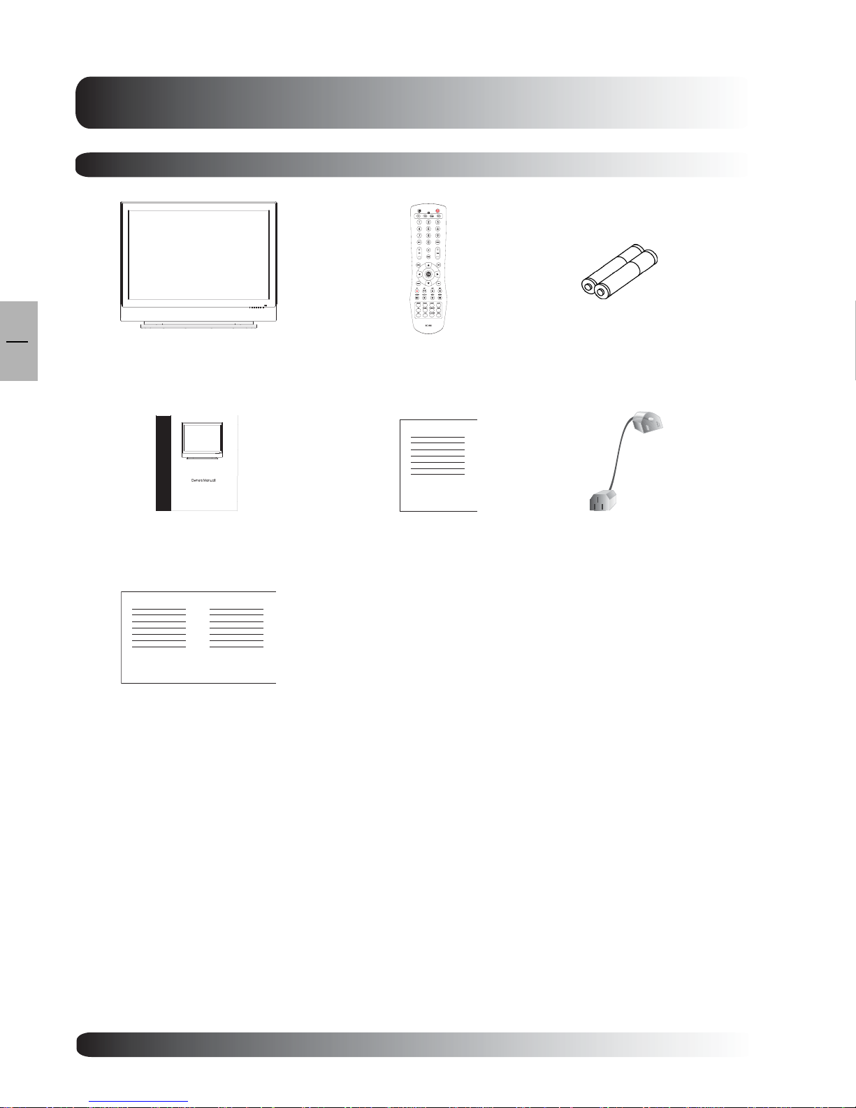
Package Contents
8
Flat Panel TV Remote Control Batteries
User Manual Warra nty Card
Quick Start Guide
Power Cord
8
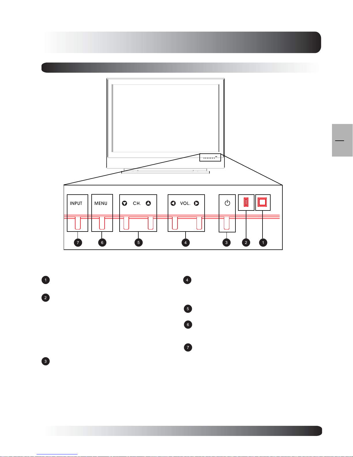
Front Panel Controls
Getting to Know Your TV
EN
9
Infrared Receiver
Receive IR signal from the remote control.
Status LED
Orange - Standby (Power OFF) with AC
power detected
The LED will illumin ate in orange color if the
TV is shut-off but the main power cord is
plugged into•the back of the unit.
Solid Green - Power ON
Receive IR signal from the remote control.
Power (Standby) Button
Turns power on or of f from sta ndby mode. There is
a wait period between on or off cycles.
V olume Adjustment Buttons
Use these buttons to adjust volume up a nd down.
These keys also serve a s navigation a nd adjustment
keys when On Screen Display menu is engaged.
Channel Select Buttons
Use these buttons to select Channel up or down.
Menu Button
Use this button to engage the On Screen Display
menu.
Input Button
Use this button to switch between available inputs.
9
EN
10
Getting to Know Your TV
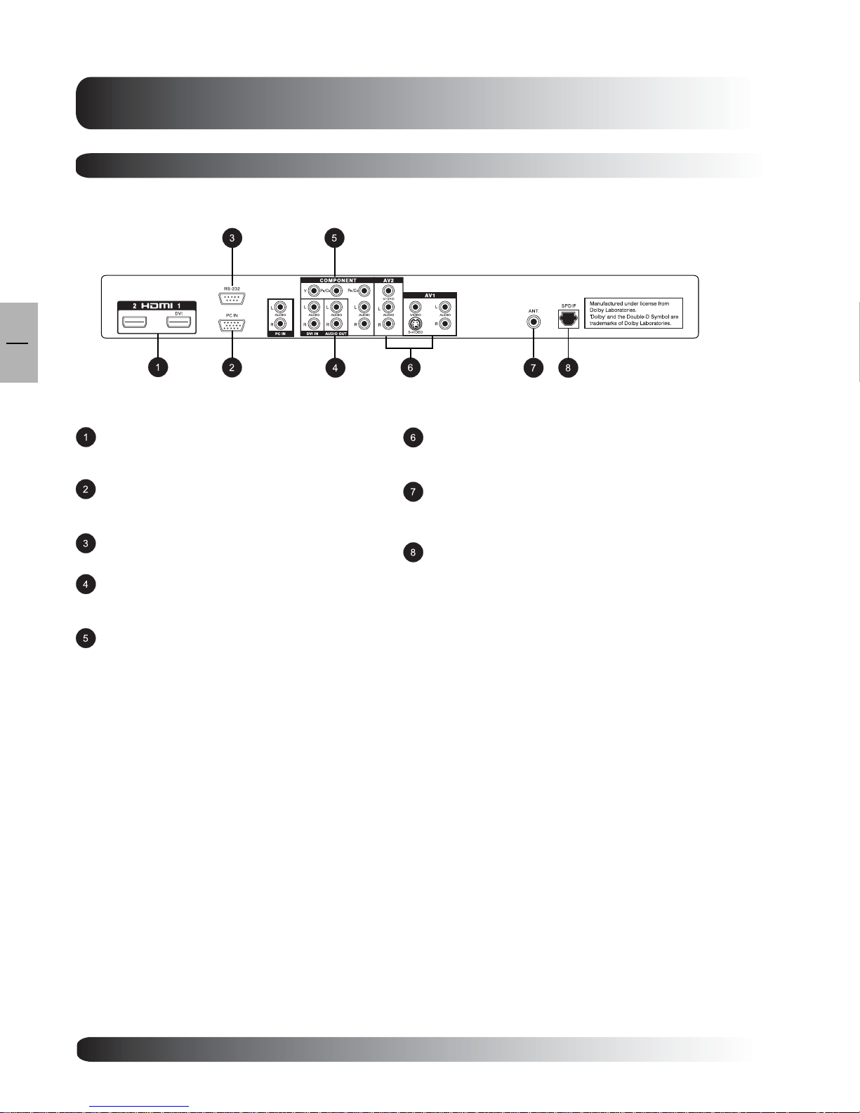
Rear Panel Connections
Digital HDMI/DVI Inputs
Connects to the digital video signals from a DVD
player or Set-Top Box.
PC Input
Connect to another computer monitor f or chaining
a pplication s.
RS-232 Connector
Connect to a computer serial port.
Audio Output
V ari a ble or f ixed audio output jacks for connecting
to an external audio amplifer.
Component Video Inputs
Auto-detecting component video inputs (Y/Pb/Pr or
Y/Cb/Cr) for connecting to the component output
jacks of a DV D player or Set-Top Box.
Composite / S-Video Inputs
Connect Composite or S-Video signals from
external sources such VCRs or DVD players.
Antenna Jack
Connect to an a ntenna, ca ble service f or sta ndard
NTSC service or digital cable for Digital TV.
SPDIF Digital Audio Output
When the Digital T V input is sele cted for viewing,
the digital audio associ ated with Digital
programming will be availa ble on this output for
connection to your home theatre system.
10
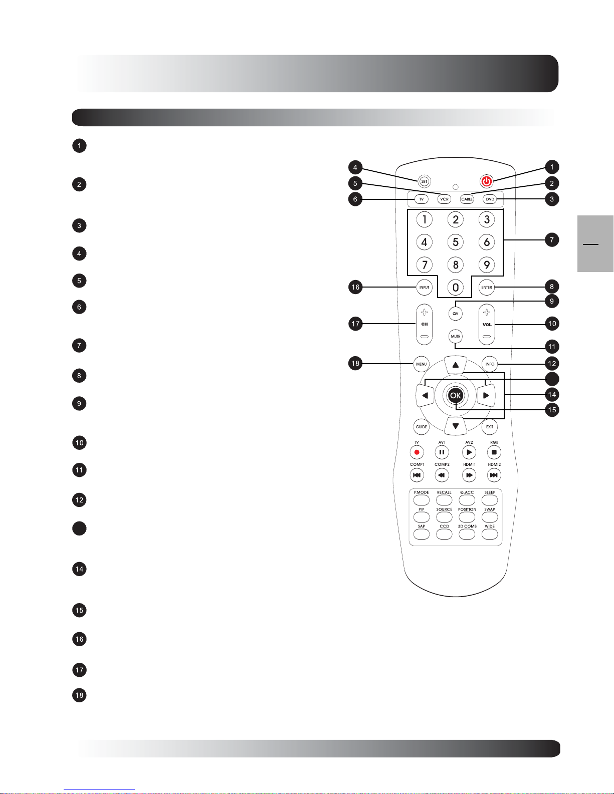
Remote Control
Standby Power On/Off
Push this button to turn on the TV from Standby mode. Push it
again to turn off to Standby mode.
Cable
Use this key to select a progra mmed ca ble TV Set-Top
Box or a programmed Satellite TV Set-Top Box.
DVD
Use this key to select a progra mmed D VD player .
SET
This key starts all progra mming sequences.
VCR
Use this key to select a programmed VCR.
TV
Use this key to select a programmed TV. Note: this key
ha s been pre-progra mmed f or this T V.
Number Keypad
Use these bottons to select cha nnels.
Enter
Use this key to confirm channel selection.
QuickView
Use this key to quickly switch between the channel
currently watched and the cha nnel previously watched.
Volume Up/Down
Adjust volume up/down.
Sound Mute On/Off
To switch the sound off a nd ba ck on again.
Info
Press to display system information.
13
Adjustment Keys
These keys serve as navigation a nd adjustment keys when On
Screen Menu is engaged.
Select Keys
These keys serve navigation and sele ction keys when On
Screen Menu is engaged.
OK
Use this key to confirm setting in OSD menu.
Input Select
Press to select input signal modes sequentially.
Channel Up/Down
Press these bottons to sele ct the next or previous cha nnel.
. Menu
Engages or turn off the OSD menu.
Note:
Component 2 direct input key is not applicable to this display .
Getting to Know Your TV
EN
11
13
11
EN
12
Getting to Know Your TV
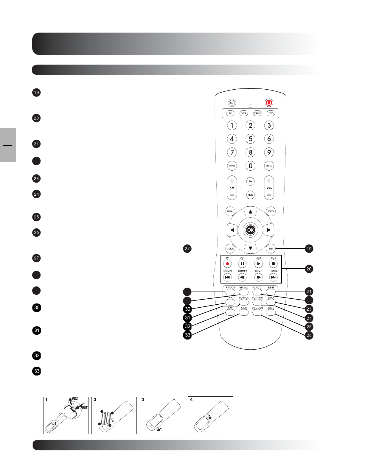
Remote Control (con’t)
Exit
Press to return to previous menu when On Screen Display
Menu is engaged.
Directly Input Selection Keys
Direct change input sign al selection by pre ssing the
appropriate key.
Sleep Ti mer
Engages Sleep Timer settings.
22
Quick Access Menu
Engages Quick Access Menu.
Swap
This key is not applicable to this TV.
Position
This key changes the PIP sub-window to 4 dif ferent corner
locations.
Wide
Toggles between various a spect ratio settings.
3D Digital COMB
Filter Direct key. Turn 3D Digital Filter On and Off under
AV mode.
Guide
This key is not a pplicable for this TV.
28
Picture Mode
Press to select Picture Modes sequentially.
29
Recall
Recall default picture settings.
PIP (Picture-in-Picture Button)
Turns on PIP feature under TV input mode. Press
it again to turn off PIP feature.
PIP Source
Change the input source of the TV PIP sub-window
among A V input sources.
SAP
This key is not available for this TV.
Closed Captioning
Turns on Closed Captioning Mode.
28
29
22
Battery Installation
12

Display Connections
Display
EN
13
Connections
13
EN
14
Display Connections
Connecting TV, CATV or ATSC
Connecting to TV, Cable TV or ATSC
Connecting the RF cable from the a ntenn a or
cable socket to the RF connector labeled as
ANT. on the back of the TV.
Antenna
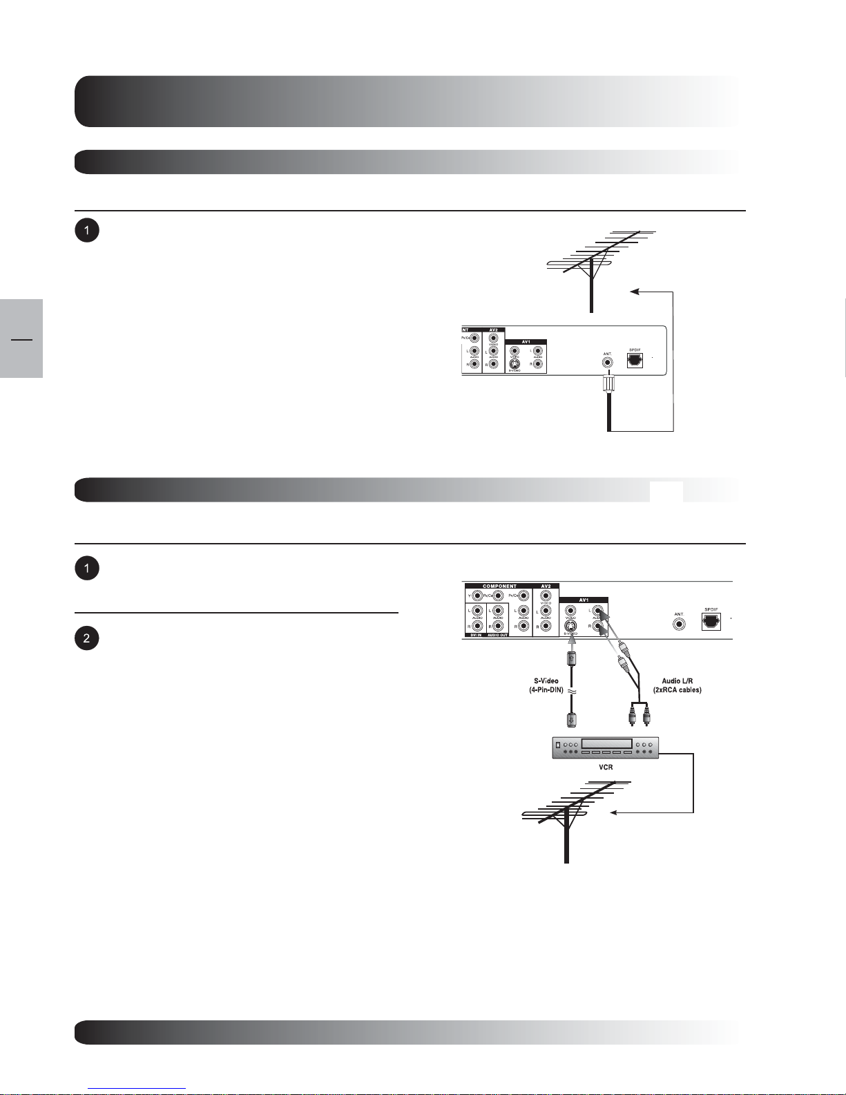
Connecting a VCR
Using S-Video Input
Connect the S-Video (4-pin DIN) connector
from the VCR to the S-Video input on the back
of TV.
Connect the red (R) and white (L) audio output
from the VCR to the R and L audio in p ut
located next to the S-Video connector.
Note:
For TV Channels setup plea se refer to VCR
user manual for details.
Ant. In
Antenna
14
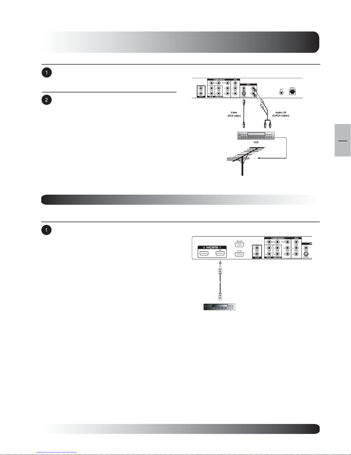
Using Composite Input
Connect the Video (yellow) out connector from
the VCR to the Video (yellow) in put on the back
of TV.
Connect the red (R) and white (L) audio output
from the VCR to the R and L audio input located
next to the Video (yellow) connector.
Display Connections
Note:
There are two sets of composite inputs
provided.
For TV Channels setup please refer to VCR
user manual for details.
Connecting a DVD
Using HDMI Input
Connect the HDMI Connector from the DVD to
the HDMI input located on the back of the TV.
HDMI Cable
Antenna
Ant. In
EN
15
DVD PLAYER
15
Display Connections
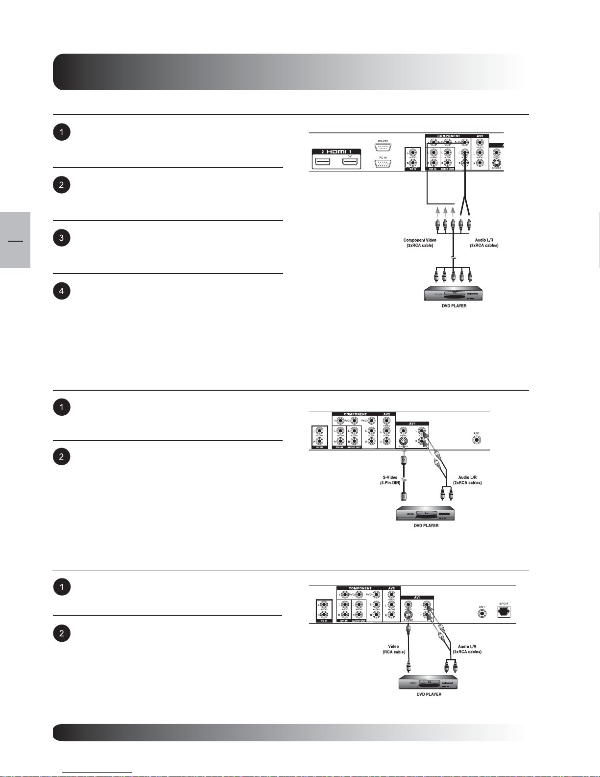
Using Component Video Input
Connect the green-colored (labeled a s Y) ja ck
from the DVD to the green-colored input of the
TV.
Connect the red-colored (labed a s PR or C R)
jack from the D VD to the red-colored PR/CR input
of the TV.
EN
16
Connect the blue-colored (labed as PB or CB)
jack from the DVD to the blue-colored PB/CB
input of the TV.
Connect the red (R) a nd white (L) audio ja ck s
from the DVD to the R and L audio-in input
located next to the PR/CR connector.
Using S-Video Input
Connect the S-Video (4-pin DIN) connector from
the DVD to the S-Video input on the back of TV.
Connect the red (R) and white (L) audio jacks
from the DVD to the R a nd L audio-in inputs
located next to the S-Video connector.
Using Composite Input
Connect the Video (yellow) out connector from
the DVD to the V ideo (yellow) in put on the back
of TV.
Connect the red (R) and white (L) audio-out
jacks from the D VD to the R and L audio-in
inputs located next to the Video (yellow)
connector.
Note:
There are two sets of composite inputs provided.
16
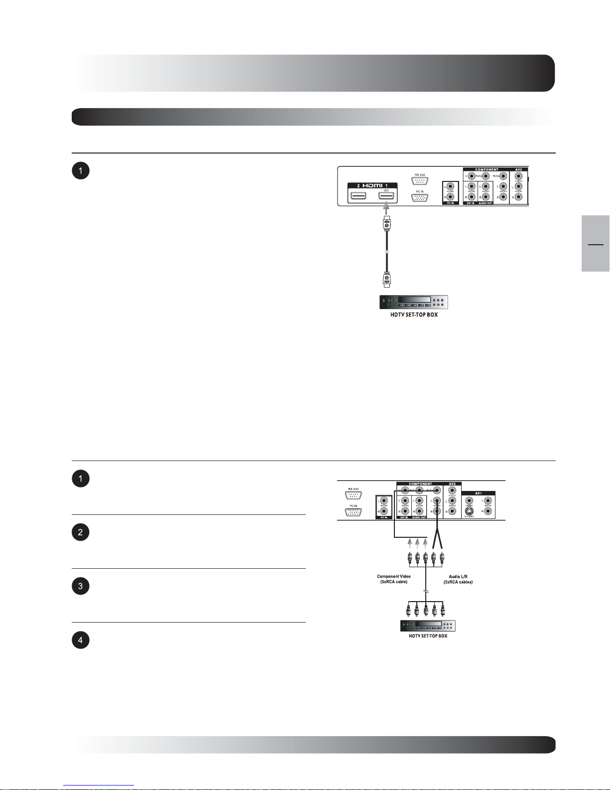
Connecting a Set-Top Box
Using HDMI Input
Connect the HDMI connector from the back of
the HDTV Set-Top Box to the HDMI input
located on the back of the TV.
Display Connections
HDMI
Notes:
Some HDTV Set-T op Boxes may not have a HDMI output. Use Component V ideo in put or PC input
method if this is the ca se.
Upon connecting your HDTV Set-Top Box to the HDMI input of the TV, it may be necessary to adjust
various picture settings on the TV to correctly match the output of the HDTV Set-Top Box. This is
caused by the different video timings set by various HDTV Set-Top Box manufa cturers.
Using Component Video Input
Some HDTV Set-Top Boxes may not have a Component Video output. Instead, use PC input method.
Connect the green-colored (labeled as Y) jack
from the Set-T op Box to the green-colored in put
of the TV.
EN
17
Connect the red-colored (labed as PR or CR)
jack from the Set-Top Box to the red-colored
PR/CR input of the TV.
Connect the blue-colored (labed a s PB or CB)
jack from the Set-Top Box to the blue-colored
PB/CB input of the TV.
Connect the red (R) and white (L) audio jacks
from the Set-T op Box to the R and L audio-in
inputs located next to the PR/CR connector.
17
Display Connections
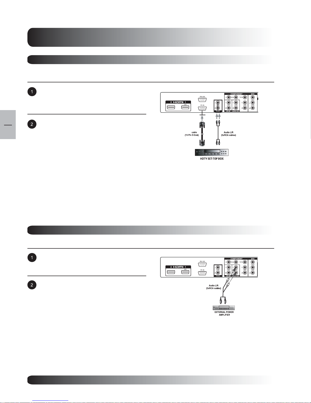
Connecting a Set-Top Box
Using TV Input
Connect the 15-pin D-Sub RGB connector from
the back of the HDTV Set-Top Box to the PC-IN
Connector located on the back of the TV.
EN
18
Connect the red (R) and white (L) audio-out
jac ks from the HDTV Set-Top Box to the R and
L audio-in jacks located next to the PC-IN
Connector.
Notes:
Some HDTV Set-T op Boxes may not have a PC output. Use Component V ideo in put or HDMI input
method if this is the ca se.
Upon connecting your HDTV Set-Top Box to the PC in put of the TV , it may be ne cessary to adjust
various picture settings on the TV to correctly match the output of the HDTV Set-Top Box. This is
caused by the different video timings set by various HDTV Set-Top Box manufa cturers.
RGB
External Audio Connections
Connecting to External Amplifiers
This TV ca n be connected to a n extern al
a mplif ier using the AUDIO OUT ja ck s located on
the back of the TV.
Connect the red (R) a nd white (L) AUDIO OUT
jacks from right side of the connector panel to
the external amplifier.
Note:
The AUDIO OUT RCA jacks can be set to
either Fixed or Variable audio output levels.
18
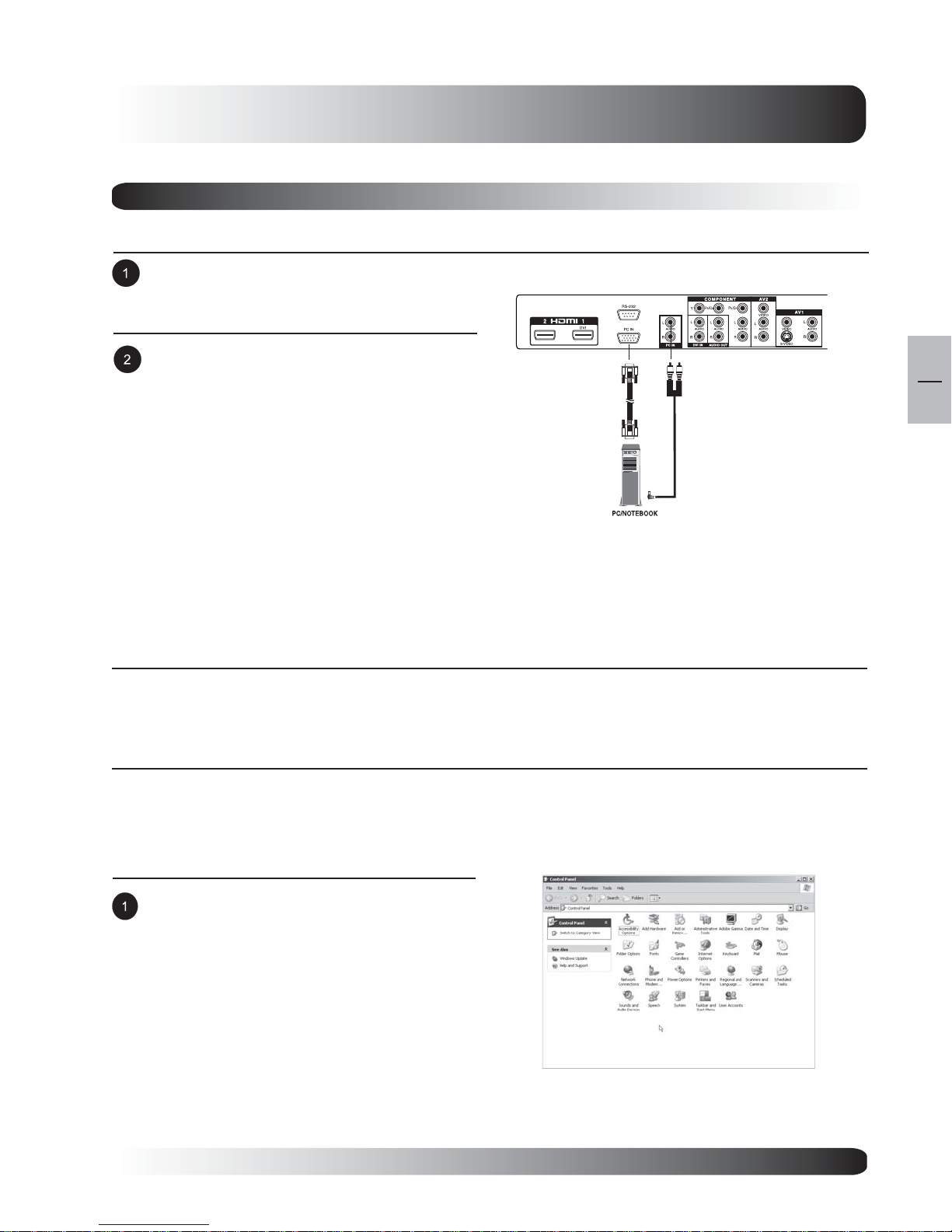
Connecting a PC
Using PC Video Input
For most PCs, connect the 15-pin D-Sub RGB
connector from the back of the PC to the PC-IN
Connector located on the back of the PC.
Connect the red (R) and white (L) audio jacks
from the PC to the R and L in puts located next
to the PC-IN Connector.
Display Connections
RGB Cable
(15 Pin D-Sub)
Audio
(3.5 mm Mini-Stereo to RCA cable)
EN
19
Setting Up Your TV Using Plug and Play
This TV adheres to VESA Plug and Play standard to eliminate complications when setting up the TV. This TV
identifies itself to the computer and automatically sends the PC its Extended Display Identification Data (EDID)
using Display Data Cha nnel (DDC) protocols.
How to Set up Your PC for Use with TV (Windows)
The display settings for a typical Windows-based computer are shown below; however, actual screens on your
computer will differ depending on the version of Windows a nd video card equi pped with the computer . Even
though the actual screen may look different from example displayed below, basic set-up routine will apply in
most cases.
Go to Window’s CONTROL PANEL by clicking:
ST AR T , SETTINGS, CONTROL PANEL. The
CONTROL PANEL Window is displayed.
Select the DISPLAY icon from this window.
19

Display Connections
Connecting a PC (con’t)
The DISPLAY PROPERTIES dialog box is
displayed. Select the SETTINGS table to display
your computer’s video output settings.
Set the “Screen Resolution” settings to 1280x1024
PIXELS. For COLOR QUALITY, select 32 BIT
COLOR (might also be expressed a s 16 million
colors).
EN
20
If a vertical-frequency option exists, set the value to
60 or 60 Hz.
Click OK to complete the setting.
Note:
Both screen position and size will vary, de pending on the type of PC graphics card and its resolution
selected.
Supported Resolutions
This TV supports the following resolutions
Horizontal Vertical
Frequency Frequency Dot Rate Vertical Horizontal
Dot x Line (KHz) (Hz) (MHz) Polarity Polarity
720 x 400@70Hz 31.469 70.087 28.322 + 640 x 480@60Hz 31.469 59.940 25.175 - 800 x 600@60Hz 37.879 60.317 40.000 + +
1024 x 768@60Hz 48.363 60.004 65.000 - 1360 x 768@60Hz 47.712 60.015 85.500 + +
1280 x 720p@60Hz 45.000 60.000 74.250 + +
1280 x 1024@60Hz 63.981 60.020 108.00 + +
1920 x 1080i@60Hz 33.750 60.000 74.250 + +
720 x 480p@60Hz 31.469 59.940 27.000 - -
Note:
This TV does not support Ma cintosh re solution s.
Resolution with is only available for 50” TV.
20
Basic Operations
Basic
EN
21
Operations
21
EN
Basic Operations
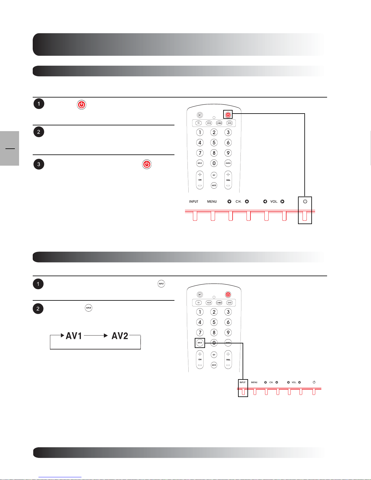
Powering On/Off
Using Front Panel or Remote Control
Press the key on the panel or the remote
control.
The TV will now turn on after a brief pause. The
ST ATUS LED will now turn green to indicate
power on status.
22
To turn power off, simply press the key on
the panel or the remote control once again.
Changing Inputs
Using Front Panel or Remote Control
Press the INPUT key on the pa nel or the
key on the remote control.
Pressing the key will cycle the TV through
all available input signal sources in the following
order:
Input Select
(Toggle)
22
Basic Operations
Using Direct Input Selection Keys
If you prefer not to cycle through all available inputs, you ca n use the Direct Input Selection keys located
towards the bottom of the remote control.
Simply select the input that you would like to
switch to and press the Direct Input Selection
keys for that input.
Note:
Component 2 direct input key is not
applicable to this TV.
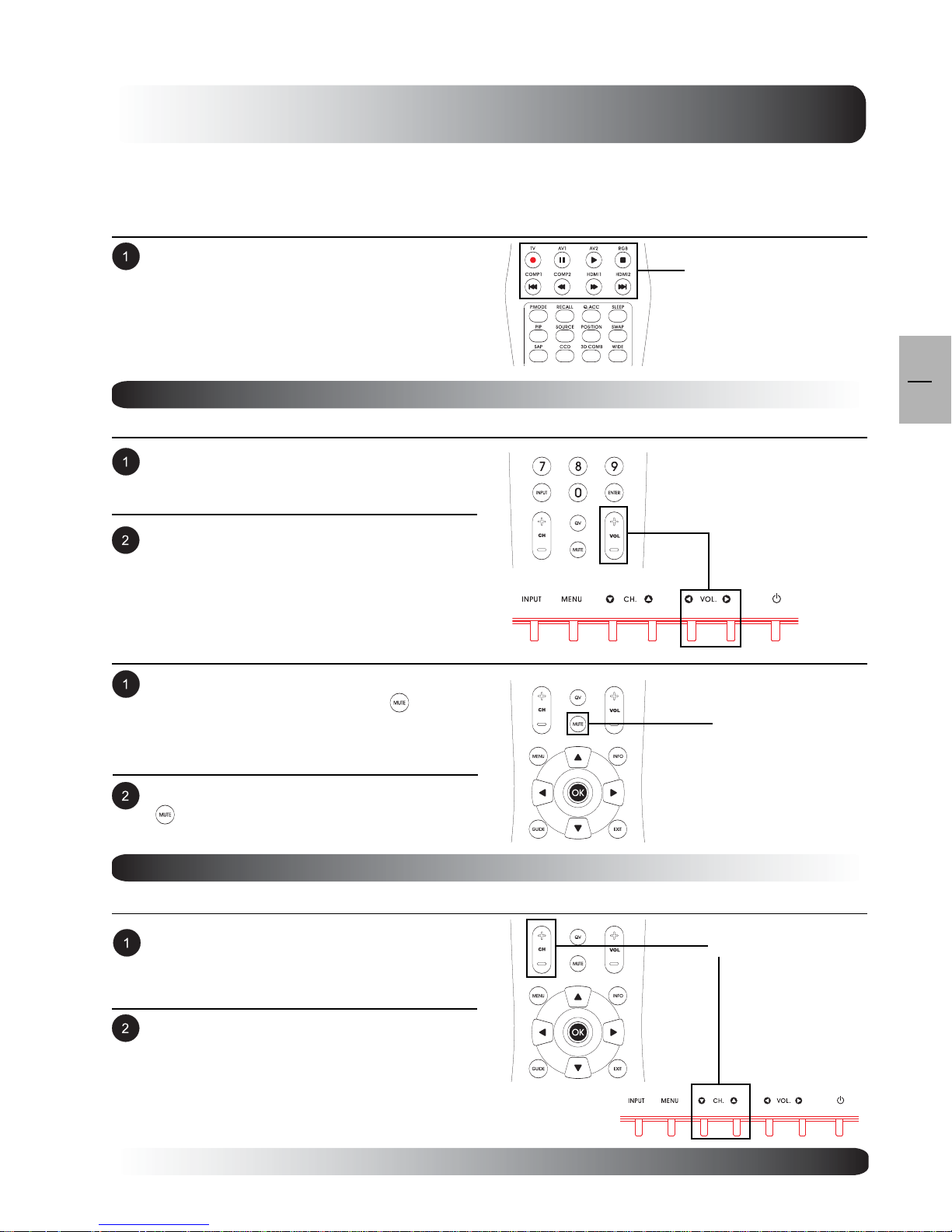
Volume Adjustment
Using Front Panel or Remote Control
To turn up sound volume, press VOLUME + on
either the front panel of TV or VOL + key on the
remote control.
To turn down sound volume, press VOLUME on either the front panel of TV or VOL - key on
the remote control.
Using MUTE
If you would like to silence the volume on a
temporary basis, simply press the key to
silence the volume. When the TV volume is
muted, the TV will display MUTE on the upper
right corner of the screen.
Direct Input
Selection Keys
EN
23
VOLUME +/-
MUTE
To disengage the mute mode, simply press the
key again or the volume buttons.
Channel Up/Down
Using Front Panel or Remote Control
To adjust TV channel up, press channel up on
either the front panel of TV or CH + key on the
remote control.
To adjust TV cha nnel down, press channel down
on either the front panel of TV or CH - key on
the remote control.
Channel Up/Down
23
EN
24
Basic Operations
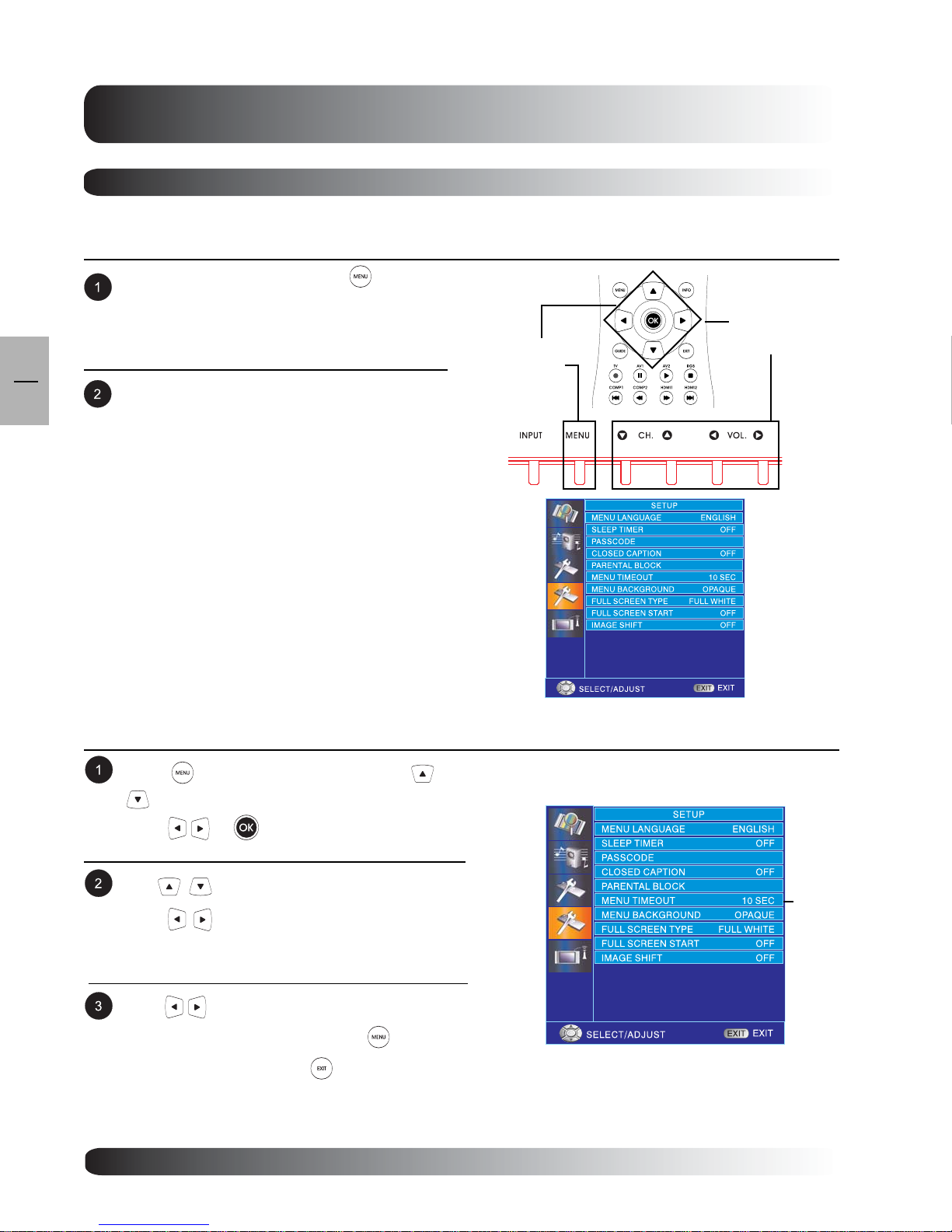
On-Screen Display Menu
Accessing OSD Menu via Remote Control or Front Panel
The On-Screen Display (OSD) menu allows access to setup various parameters equi pped with this T V.
To access the OSD menu, press button or
menu key on the front panel of TV.
OSD Menu
OSD Menu
Access
Navigation through the OSD Menu can be
accomplished using the arrow keys on the
remote control or using the front panel control
keys.
Navigation
OSD Menu Timeout Setting
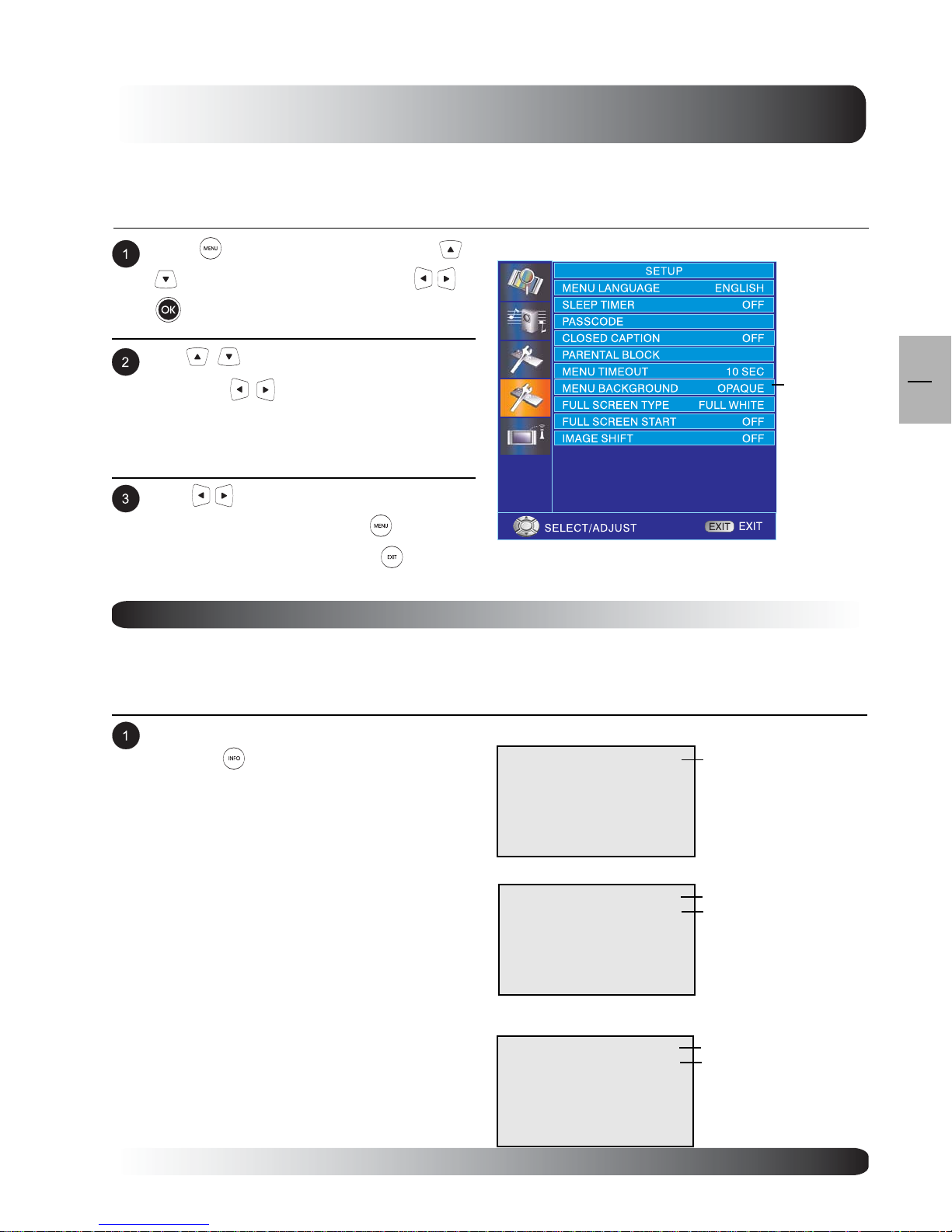
OSD Menu will automatically disappear after a preset period of time so that it doesn’t remain on the screen. To
change the menu timeout period, ple ase follow the steps below .
Press to access the OSD menu. Use
keys to select SETUP from menu then
press
Use to select MENU TIMEOUT then
press
Use keys to change your settings. After
achieving the disired setting, press key to return
to previous menu or press to exit menu.
or to enter SETUP menu.
to enter MENU TIMEOUT setting.
MENU
TIMEOUT
24
Basic Operations
OSD Menu Background Color Setting
The background color of the OSD Menu can be customized. To change the MENU Ba ckground color setting,
please f ollow the steps below .
Press to access the OSD menu. Use
keys to select SETUP then press
to enter SETUP menu.
Use keys to select BACKGROUND
then press
GROUND COLOR setting.
Use keys to change your settings. After
achieving disired setting, press key to
return to previous menu or press to exit
menu.
to enter MENU BACK-
or
MENU
BACKGROUD
On-Screen Status Display
Displaying Status
The On-Screen Status Display shows detailed inf ormation regarding the operation al status of the TV. The status
display automatically ap pears whenever there is a change in the state of the TV such as channel cha nge or input
change. The status display will automatically disappear after a period of time.
EN
25
To manually show the Status Display, simply
press the key on the remote control.
Note:
When using A V1 priority is given to the S-
Video input.
When using S-Video connection AV1 the
status display will denote “[S]” to indicate
the input source is using S-Video
connector.
AV Mode
AV1
Component/ HDMI Modes
COMPONENT1
1080I
PC Mode
PC
640x480
Input Source
Signal Format
Input Source
Signal Format
Input Source
25
EN
26
Basic Operations
Understanding Widescreen Modes
This TV is capable of displaying a widescreen image on the n ative 16:9 aspect ratio screen. However , not all
available video content fits perfectly in a widescreen (16:9) format resulting in unused screen space. This TV
is capa ble of displaying images in various formats that is suitable for various types of content depending on its
size.
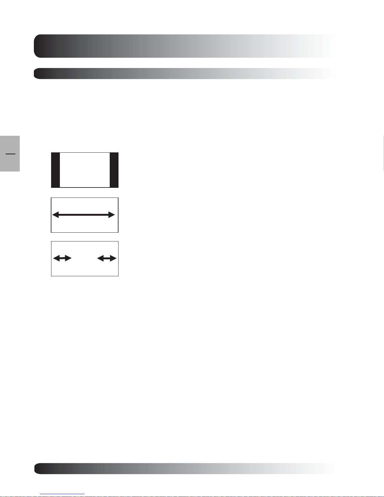
For 4:3 (Square) Content
Content from traditional TV, VCR, and some DVD’s are formatted using a “square” 4:3 format. When
viewing content in this “Square” format the following viewing modes are suitable.
4:3 (NORMAL)
In 4:3 mode, the original 4:3 image is preserved but black bars are used to fill
the the extra space on the left and right.
16:9 (FULL)
The original 4:3 image is proportionally stretched to fill the entire screen. This
is the default setting from factory.
PANOROMIC
The original 4:3 image is expa nded in both the horizontal a nd vertical
directions. The center of the picture is almost normal while the edges are
considerably expanded.
26
 Loading...