


LCD Projector
MC-CW301/MC-CX301
User's Manual (detailed)
Operating Guide – Technical
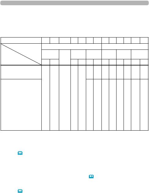
Supported signals for COMPUTER IN
Resolution (H x V) |
Signal mode |
H. frequency (kHz) |
V. frequency (Hz) |
Rating |
|
|
|
|
|
720 x 400 |
TEXT |
37.9 |
85 |
VESA |
640 x 480 |
VGA (60Hz) |
31.5 |
59.9 |
VESA |
|
VGA (72Hz) |
37.9 |
72.8 |
VESA |
|
VGA (75Hz) |
37.5 |
75 |
VESA |
|
VGA (85Hz) |
43.3 |
85 |
VESA |
800 x 600 |
SVGA (56Hz) |
35.2 |
56.3 |
VESA |
|
SVGA (60Hz) |
37.9 |
60.3 |
VESA |
|
SVGA (72Hz) |
48.1 |
72.2 |
VESA |
|
SVGA (75Hz) |
46.9 |
75 |
VESA |
|
SVGA (85Hz) |
53.7 |
85.1 |
VESA |
832 x 624 |
Mac 16” mode |
49.7 |
74.5 |
|
1024 x 768 |
XGA (60Hz) |
48.4 |
60 |
VESA |
|
XGA (70Hz) |
56.5 |
70.1 |
VESA |
|
XGA (75Hz) |
60 |
75 |
VESA |
|
XGA (85Hz) |
68.7 |
85 |
VESA |
1152 x 864 |
1152 x 864 (75Hz) |
67.5 |
75 |
VESA |
1280 x 768 |
W-XGA (60Hz) |
47.7 |
60 |
VESA |
1280 x 800 |
1280 x 800 (60Hz) |
49.7 |
60 |
VESA |
1280 x 1024 |
SXGA (60Hz) |
64 |
60 |
VESA |
|
SXGA (75Hz) |
80 |
75 |
VESA |
|
SXGA (85Hz) |
91.1 |
85 |
VESA |
1366 x 768 |
WXGA (60Hz) |
47.7 |
59.8 |
VESA |
1440 x 900 |
WXGA+ (60Hz) |
55.9 |
59.9 |
VESA |
1600 x 900 |
WXGA++ (60Hz) |
60 |
60 |
VESA |
*1 1400 x 1050 |
SXGA+ (60Hz) |
65.2 |
60 |
VESA |
*2 1680 x 1050 |
WSXGA+ (60Hz) |
65.3 |
60 |
VESA |
1600 x 1200 |
UXGA (60Hz) |
75 |
60 |
VESA |
1920 x 1080 |
Full HD (60Hz) |
67.5 |
60 |
VESA |
*1) Only for [XGA Model] *2) Only for [WXGA Model]
NOTE •Besuretocheckjacktype,signallevel,timingandresolutionbeforeconnectingthisprojectortoaPC.
•SomePCsmayhavemultipledisplayscreenmodes.Useofsomeofthesemodeswillnotbepossiblewiththisprojector.
•Depending on the input signal, full-size display may not be possible in some cases. Refer to the number of display pixels above.
•The signal will be converted to the projector’s panel resolution before being displayed. The best display performance will be achieved if the resolutions of the input signal and projector panel are identical.
•Automatic adjustment may not function correctly with some input signals.
•The image may not be displayed correctly when the input sync signal is a composite sync or a sync on G.
•The illustrations in this manual are for illustrative purposes. They may differ slightly from your projector.
1 |
QM00612-1 |

Supported signals
Supported signals for HDMI
Resolution (H x V) |
Signal mode |
H. frequency |
V. frequency |
Rating |
|
|
(kHz) |
(Hz) |
|
|
|
|
|
|
720 x 400 |
TEXT |
37.9 |
85 |
VESA |
640 x 480 |
VGA (60Hz) |
31.5 |
59.9 |
VESA |
|
VGA (72Hz) |
37.9 |
72.8 |
VESA |
|
VGA (75Hz) |
37.5 |
75 |
VESA |
|
VGA (85Hz) |
43.3 |
85 |
VESA |
800 x 600 |
SVGA (56Hz) |
35.2 |
56.3 |
VESA |
|
SVGA (60Hz) |
37.9 |
60.3 |
VESA |
|
SVGA (72Hz) |
48.1 |
72.2 |
VESA |
|
SVGA (75Hz) |
46.9 |
75 |
VESA |
|
SVGA (85Hz) |
53.7 |
85.1 |
VESA |
832 x 624 |
Mac 16” mode |
49.7 |
74.5 |
|
1024 x 768 |
XGA (60Hz) |
48.4 |
60 |
VESA |
|
XGA (70Hz) |
56.5 |
70.1 |
VESA |
|
XGA (75Hz) |
60 |
75 |
VESA |
|
XGA (85Hz) |
68.7 |
85 |
VESA |
1152 x 864 |
1152 x 864 (75Hz) |
67.5 |
75 |
VESA |
1280 x 768 |
W-XGA (60Hz) |
47.7 |
60 |
VESA |
1280 x 800 |
1280 x 800 (60Hz) |
49.7 |
60 |
VESA |
1280 x 1024 |
SXGA (60Hz) |
64 |
60 |
VESA |
|
SXGA (75Hz) |
80 |
75 |
VESA |
|
SXGA (85Hz) |
91.1 |
85 |
VESA |
1366 x 768 |
WXGA (60Hz) |
47.7 |
59.8 |
VESA |
1440 x 900 |
WXGA+ (60Hz) |
55.9 |
59.9 |
VESA |
1600 x 900 |
WXGA++ (60Hz) |
60 |
60 |
VESA |
1400 x 1050 |
SXGA+ (60Hz) |
65.2 |
60 |
VESA |
1680 x 1050 |
WSXGA+ (60Hz) |
65.3 |
60 |
VESA |
1600 x 1200 |
UXGA (60Hz) |
75 |
60 |
VESA |
720(1440) x 480i |
480i |
15.7 |
60 |
CEA |
720(1440) x 576i |
576i |
15.6 |
50 |
CEA |
720 x 480p |
480p |
31.5 |
60 |
CEA |
720 x 576p |
576p |
31.3 |
50 |
CEA |
1280 x 720p |
720p (50Hz) |
37.5 |
50 |
CEA |
|
720p (60Hz) |
45 |
60 |
CEA |
1920 x 1080i |
1080i (50Hz) |
28.1 |
50 |
CEA |
|
1080i (60Hz) |
33.8 |
60 |
CEA |
1920 x 1080p |
1080p (50Hz) |
56.3 |
50 |
CEA |
|
1080p (60Hz) |
67.5 |
60 |
CEA |
2 |
QM00612-1 |
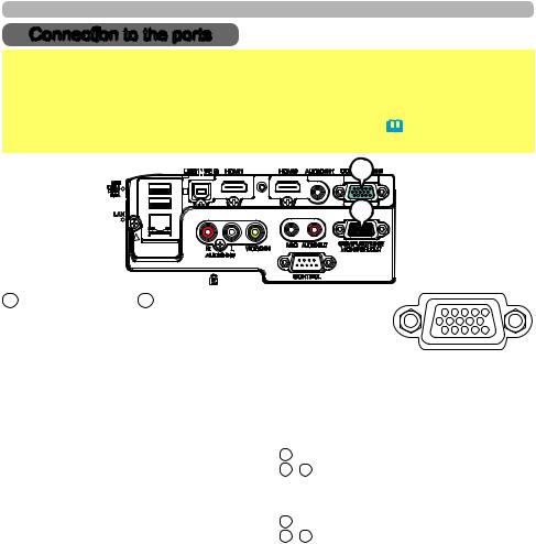
Connection to the ports
Connection to the ports
NOTICE ►Use the cables with straight plugs, not L-shaped ones, as the input ports of the projector are recessed.
►Only the signal that is input from the COMPUTER IN1 can be output from the COMPUTER IN2/MONITOR OUT port. The way is available only when the MONITOR OUT is selected for the COMPUTER IN2. (&INPUT menu - COMPUTER IN in the User's Manual - Operating Guide)
A |
B |
A COMPUTER IN1, B COMPUTER IN2/MONITOR OUT
D-sub 15pin mini shrink jack
(1) for PC signal
•Video signal: RGB separate, Analog, 0.7Vp-p, 75Ω terminated (positive)
•H/V. sync. Signal: TTL level (positive/negative)
•Composite sync. Signal: TTL level
Pin |
Signal |
Pin |
Signal |
|
|
|
|
|
|
1 |
Video Red |
10 |
Ground |
|
2 |
Video Green |
11 |
(No connection) |
|
3 |
Video Blue |
12 |
A : SDA(DDC data) |
|
4 |
(No connection) |
B , C : (No connection) |
||
|
||||
5 |
Ground |
13 |
H. sync / Composite sync. |
|
6 |
Ground Red |
14 |
V. sync. |
|
7 |
Ground Green |
15 |
A : SCL (DDC clock) |
|
8 |
Ground Blue |
B , C : (No connection) |
||
|
||||
9 |
(No connection) |
- |
- |
(2) for Component signal
•Y : Component video Y with composite sync, 1.0±0.1 Vp-p, 75 Ω terminator
•Cr/Pr : Component video Cr/Pr, 0.7±0.1 Vp-p, 75 Ω terminator
•Cb/Pb : Component video Cb/Pb, 0.7±0.1 Vp-p, 75 Ω terminator
System:480i@60,480p@60,576i@50,576p@50,720p@50/60,1080i@50/60,1080p@50/60
Pin |
|
Signal |
Pin |
Signal |
|
|
|
|
|
1 |
Cr/Pr |
|
9 |
(No connection) |
2 |
Y |
|
10 |
Ground |
3 |
Cb/Pb |
|
11 |
(No connection) |
4 |
(No connection) |
|
12 |
(No connection) |
5 |
Ground |
|
13 |
(No connection) |
6 |
Ground Cr/Pr |
|
14 |
(No connection) |
7 |
Ground Y |
|
15 |
(No connection) |
8 |
Ground Cb/Pb |
|
- |
- |
3 |
QM00612-1 |
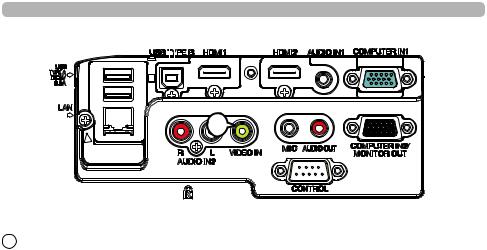
Connection to the ports (continued)
C
C VIDEO IN
RCA jack
•System: NTSC, PAL, SECAM, PAL-M, PAL-N, NTSC4.43, PAL(60Hz)
•1.0±0.1Vp-p, 75Ω terminator
4 |
QM00612-1 |

Connection to the ports (continued)
D |
|
E |
F |
|
|
|
|
G |
H |
J |
I |
DHDMI1 E HDMI2
•Type :Digital audio/video connector
•Audio signal : Linear PCM (Sampling rate; 32/44.1/48 kHz)
2 4 6 8 10 12 14 16 18
1 3 5 7 9 11 13 15 17 19
Pin |
Signal |
Pin |
Signal |
Pin |
Signal |
1 |
T.M.D.S. Data2 + |
8 |
T.M.D.S. Data0 Shield |
15 |
SCL |
2 |
T.M.D.S. Data2 Shield |
9 |
T.M.D.S. Data0 - |
16 |
SDA |
3 |
T.M.D.S. Data2 - |
10 |
T.M.D.S. Clock + |
17 |
DDC/CEC Ground |
4 |
T.M.D.S. Data1 + |
11 |
T.M.D.S. Clock Shield |
18 |
+5V Power |
5 |
T.M.D.S. Data1 Shield |
12 |
T.M.D.S. Clock - |
19 |
Hot Plug Detect |
6 |
T.M.D.S. Data1 - |
13 |
CEC |
|
|
7 |
T.M.D.S. Data0 + |
14 |
Reserved(N.C. on device) |
|
|
F AUDIO IN1
Ø3.5 stereo mini jack
• 22kΩ terminator
AUDIO IN2 G R, H L
RCA jack x2
• 22kΩ terminator
I AUDIO OUT
Ø3.5 stereo mini jack
• 1kΩ output impedance
J MIC
Ø3.5 mono mini jack <Low level>
•2 mVrms, 1kΩ terminator <High level>
•20 mVrms, 1kΩ terminator
5 |
QM00612-1 |
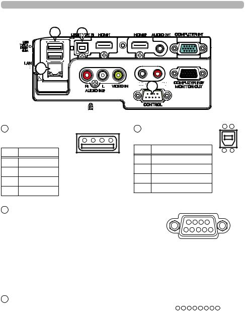
Connection to the ports (continued)
K |
L |


 N
N


 M
M


K USB TYPE A |
|
L USB TYPE B |
|
|
|
||
USB A type jack |
4 3 2 1 |
USB B type jack |
|
|
|
||
Pin |
Signal |
|
Pin |
Signal |
|
|
|
|
1 |
+5V |
|
|
|
||
1 |
+5V |
|
|
|
|
||
|
2 |
- Data |
|
|
|
||
2 |
- Data |
|
|
|
|
||
|
3 |
+ Data |
|
|
|
||
3 |
+ Data |
|
|
|
|
||
|
4 |
Ground |
|
|
|
||
4 |
Ground |
|
|
|
|
||
|
|
|
|
|
|
||
M CONTROL |
|
|
|
|
|
|
|
D-sub 9pin plug |
|
|
9 |
8 |
7 |
6 |
|
• About the details of RS-232C communication, |
|
5 |
4 3 |
2 |
1 |
||
please refer to the section "RS-232C Communication". |
|
|
|
|
|||
4 3
1 2
Pin |
Signal |
Pin |
Signal |
Pin |
Signal |
|
|
|
|
|
|
1 |
(No connection) |
4 |
(No connection) |
7 |
RTS |
2 |
RD |
5 |
Ground |
8 |
CTS |
3 |
TD |
6 |
(No connection) |
9 |
(No connection) |
N LAN
RJ-45 jack |
|
|
|
1 |
2 |
3 |
4 |
5 |
6 |
7 |
|
8 |
|
|
|||||||||
|
|
|
|
|
|
|
|
||||||||||||||||
|
|
|
|
|
|
|
|
|
|
|
|
|
|
|
|
|
|
|
|
|
|
|
|
|
|
|
|
|
|
|
|
|
|
|
|
|
|
|
|
|
|
|
|
|
|
|
|
Pin |
Signal |
Pin |
Signal |
Pin |
Signal |
|
|
|
|
|
|
|
|
|
|
|
|
|
|
|
|
|
|
|
|
|
|
|
|
|
|
|
|
|
|
|
|
|
|
|
|||||||
|
|
|
|
|
|
|
|
|
|
|
|
|
|
|
|
|
|
|
|
|
|
|
|
1 |
TX+ |
4 |
- |
7 |
- |
|
|
|
|
|
|
|
|
|
|
|
|
|
|
|
|
|
|
2 |
TX- |
5 |
- |
8 |
- |
|
|
|
|
|
|
|
|
|
|
|
|
|
|
|
|
|
|
|
|
|
|
|
|
|
|
|
|
|
|
|
|
|
|
|
|||||||
3 |
RX+ |
6 |
RX- |
|
|
|
|
|
|
|
|
|
|
|
|
|
|
|
|
|
|
|
|
|
|
|
|
|
|
|
|
|
|
|
|
|
|
|
|
|
|
|
|
|
|
|
|
6 |
QM00612-1 |
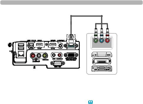
Connection to the ports (continued)
To input component video signal to COMPUTER IN ports ex.
D-sub plug


 RCA plugs
Y CB/PB CR/PR COMPONENT VIDEO OUT
RCA connectors
VCR/DVD/Blu-ray
Disc player
To input component video signal to the COMPUTER IN1 or IN2 port of the projector, use a RCA to D-sub cable or adapter.
For about the pin description of the required cable or adapter, refer to the descriptions about COMPUTER IN1 and IN2 port (&3).
7 |
QM00612-1 |
RS-232C Communication
RS-232C Communication
When the projector connects to the computer by RS-232C communication, the projector can be controlled with RS-232C commands from the computer.
For details of RS-232C commands, refer to RS-232C Communication / Network command table (&17).
Connection
Turn off the projector and the computer.
Connect the projector's CONTROL port and the computer's RS-232C port with a RS-232C cable (cross). Use the cable that fulfills the specification
shown in figure
3. Turnon. the computer on, and after the computer has started up turn the projector
4. Set the COMMUNICATION TYPE to OFF. (OPTION menu - SERVICE - COMMUNICATION in the User's Manual - Operating Guide)
RS-232C |
CONTROL |
RS-232C Cable
(cross)
RS-232C port |
CONTROL port |
|||||||||
of the computer |
of the projector |
|||||||||
9 |
8 |
7 |
|
6 |
|
9 |
8 |
7 |
|
6 |
5 |
4 |
3 |
2 |
1 |
|
5 |
4 |
3 |
2 |
1 |
|
|
CD (1) |
(1) |
|
|
|
|
|||
|
|
|
RD(2) |
(2) |
RD |
|
|
|
||
|
|
|
TD (3) |
(3) TD |
|
|
|
|||
|
|
DTR (4) |
(4) |
|
|
|
|
|||
|
GND (5) |
(5) GND |
|
|
||||||
|
|
DSR (6) |
(6) |
|
|
|
|
|||
|
|
RTS (7) |
(7) |
RTS |
|
|
||||
|
|
DTS (8) |
(8) |
CTS |
|
|
||||
|
|
|
RI (9) |
(9) |
|
|
|
|
||
8 |
QM00612-1 |
RS-232C Communication (continued)
Communication settings
1. Protocol
19200bps,8N1
2. Command format ("h" shows hexadecimal)
Byte Number |
0 |
1 |
2 |
3 |
4 |
5 |
6 |
7 |
8 |
9 |
10 |
11 |
12 |
Command |
|
|
Header |
|
|
|
|
|
|
Data |
|
|
|
|
Header |
|
Data |
CRC |
Action |
Type |
Setting |
||||||
|
code |
Packet |
size |
|
flag |
code |
|||||||
Action |
|
|
|
|
|
||||||||
L |
H |
|
L |
H |
L |
H |
L |
H |
L |
H |
L |
H |
|
<SET>Change setting to
desired value [(cL)(cH)] (aL) (aH) 01h 00h (bL) (bH) (cL) (cH) by [(bL)(bH)].
<GET>Read projector |
|
|
(aL) |
(aH) |
02h |
00h |
(bL) |
(bH) |
00h |
00h |
internal setup value [(bL) |
|
|
||||||||
(bH)] . |
|
|
|
|
|
|
|
|
|
|
<INCREMENT> |
BEh EFh |
03h 06h 00h (aL) |
(aH) |
04h |
00h |
(bL) |
(bH) |
00h |
00h |
|
Increment setup value |
||||||||||
[(bL)(bH)] by 1. |
|
|
|
|
|
|
|
|
|
|
<DECREMENT> |
|
|
(aL) |
(aH) |
05h |
00h |
(bL) |
(bH) |
00h |
00h |
Decrement setup value |
|
|
||||||||
[(bL)(bH)] by 1. |
|
|
|
|
|
|
|
|
|
|
<EXECUTE> Run a |
|
|
(aL) |
(aH) |
06h |
00h |
(bL) |
(bH) |
00h |
00h |
command [(bL)(bH)]. |
|
|
||||||||
|
|
|
|
|
|
|
|
|
|
|
[Header code] [Packet] [Data size]
Set [BEh, EFh, 03h, 06h, 00h] to byte number 0~ 4.
[CRC flag]
For byte number 5, 6, refer to RS-232C Communication / Network command table (&17).
[Action]
Set functional code to byte number 7, 8.
<SET> = [01h, 00h], <GET> = [02h, 00h], <INCREMENT> = [04h, 00h] <DECREMENT> = [05h, 00h], <EXECUTE> = [06h, 00h]
Refer to the Communication command table (&above).
[Type] [Setting code]
For byte number 9 12, refer to RS-232C Communication / Network command table (&17).
9 |
QM00612-1 |

RS-232C Communication (continued)
3. Response code / Error code ("h" shows hexadecimal)
(1) ACK reply : 06h
When the projector receives the Set, Increment, Decrement or Execute command correctly, the projector changes the setting data for the specified item by [Type], and it returns the code.
(2) NAK reply : 15h
When the projector cannot understand the received command, the projector returns the error code.
In such a case, check the sending code and send the same command again.
(3) Error reply : 1Ch + 0000h
When the projector cannot execute the received command for any reasons, the projector returns the error code.
In such a case, check the sending code and the setting status of the projector.
(4) Data reply : 1Dh + xxxxh
When the projector receives the GET command correctly, the projector returns the response code and 2 bytes of data.
NOTE • For connecting the projector to your devices, please read the manual for each devices, and connect them correctly with suitable cables.
•Operation cannot be guaranteed when the projector receives an undefined command or data.
•Provide an interval of at least 40ms between the response code and any other code.
•The projector outputs test data when the power supply is switched ON, and when the lamp is lit. Ignore this data.
•Commands are not accepted during warm-up.
•When the data length is greater than indicated by the data length code, the projector ignore the excess data code. Conversely when the data length is shorter than indicated by the data length code, the projector returns the error code to the computer.
10 |
QM00612-1 |
 Loading...