

Page 1

Page 2

Page 3

3
position
9
Board Features
Board Connector and Component Locations
®
845E Chipset
®
82845E Memory Controller Hub (MCH)
®
82801BA I/O Controller Hub (ICH2)
®
82802AB Firmware Hub (FWH)
®
Rapid BIOS Boot
®
Rapid BIOS Boot
Wake on LAN Technology
Wake on Ring
ACPI
Wake-up Devices and Events
Page 4

4
Wake from USB
Wake from PS/2 Devices
32-bit, 33-MHz PCI Subsystem
ATA-100
Video Controller
Video Modes
Video Memory Interface
3
29
30
30
30
31
31
31
31
31
Page 5

Figures
The Controls
3.
Tables
3.
Wake-up Devices and Events
Video Modes
Page 6

Page 7

The system can be used anywhere the temperature is suitable for people. However, rooms
with humidity over 70%, and dusty or dirty areas are not appropriate. In addition, do not
When you save data to your system‘s hard disks or to a floppy disk, they are stored as
ATTENTION
In order to fully separate the system from current, the power cord must be removed from
the wall outlet
Page 8
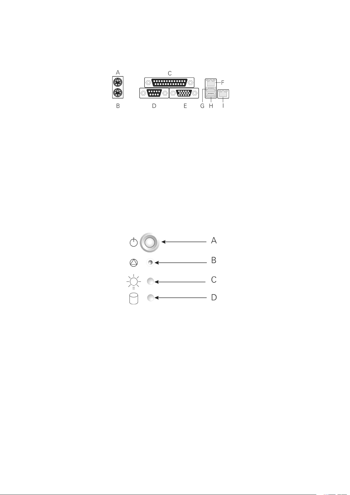
G.
C.
VGA port
At the front of the case, you can find the neccessary controls like power button, reset button
C.
Page 9

Table 1. System Board Features
®
Pentium
®
4 processor in a
®
Celeron
®
processor in a
Two 184-pin DDR SDRAM Dual Inline Memory Module (DIMM) sockets
®
845E Chipset, consisting of:
®
®
®
Two external USB ports with an additional internal header providing two
optional USB ports for front panel support
Two IDE interfaces with UDMA 33, ATA-66/100 support
Diskette B)
four embedded devices:
SDRAM
Two Intel
®
10/100 82550PM Fast Ethernet Controllers
ATA-100 controller, Promise Technology PDC20267
®
/AMI BIOS with support for:
Advanced Con guration and Power Interface (ACPI)
Wake on PME
Wake on Ring (WOR)
Wake on LAN (WOL)
Page 10
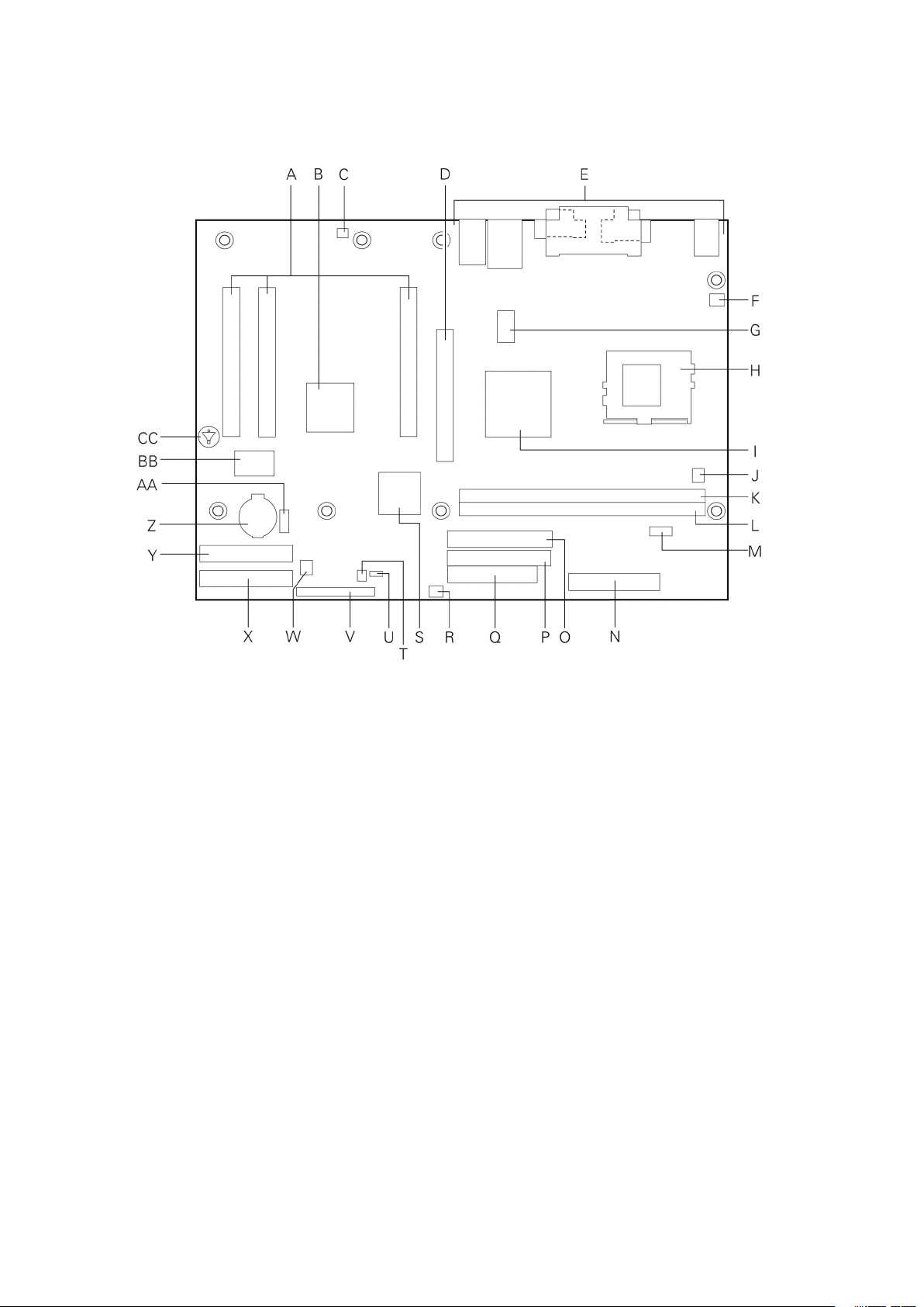
ATI Rage XL Video Controller
Q.
C.
AGP connector
S.
®
82801BA I/O controller hub (ICH2)
G.
V.
W.
®
82845E memory controller hub (MCH)
J.
Z.
AA.
CC.
Page 11

The System board board supports a single Intel
®
Pentium
®
4 processor with a µPGA478 socket.
Table 2. Supported Processors
Type
System Bus
®
®
4 processor
400 / 533 MHz
®
®
4 processor
400 MHz
®
Celeron
®
processor
400 MHz
The SE845WD1-E system board contains two 184-pin DIMM
sockets and supports up to
two DDR
SDRAM DIMMs. The minimum supported memory configuration is 64 MB and
the maximum configurable memory size is a 2 GB stacked un-buffered DDR200/266 ECC
Table 3. Supported Memory Con gurations
Capacity
Sides
SDRAM Devices
4
32 M x 8/empty
32 M x 16/empty
4
32 M x 8/32 M x 8
and memory configurations must adhere to the following:
®
or a designated memory test vendor will be
Page 12

®
845E Chipset
The Intel
®
845E chipset consists of the following devices:
®
82845E Memory Controller Hub (MCH) with Accelerated Hub Architecture (AHA)
®
82801BA I/O Controller Hub (ICH2) with AHA bus
®
82802AB Firmware Hub (FWH)
The MCH is a centralized controller for the system bus, the memory bus, the AGP bus,
®
82845E Memory Controller Hub (MCH)
The MCH supports the data integrity features supported by the Pentium
®
Pro bus, including
data while
The MCH provides the following:
An integrated Synchronous DRAM memory controller with auto detection of SDRAM.
®
82801BA I/O Controller Hub (ICH2)
The Intel
®
82801BA ICH2 has these features:
33 MHz Peripheral Component Interface (PCI) Local Bus slots supporting PCI specifica-
tion, Rev 2.2.
All PCI Slots
®
82802AB Firmware Hub (FWH)
The Intel
®
82802AB Firmware Hub
(FWH
The FWH provides the following:
Page 13

The SMSC LPC47M102 I/O Controller provides the following features:
3.3 V operation
®
The BIOS Setup program provides configuration options for the I/O controller.
The MAXDATA Fusion 6000 System board has one serial port connector and one serial port
The 25-pin D-Sub parallel port connector is located on the back panel. In the BIOS Setup
The I/O controller supports two diskette drives that are compatible with the 82077 diskette
the connection after an overcurrent condition is removed.
The keyboard is supported in the bottom PS/2 connector and the mouse is supported in
the top PS/2 connector. Power to the computer should be turned off before a keyboard or
The keyboard controller contains the AMI keyboard and mouse controller code, provides the
keyboard and mouse control functions, and supports password protection for power-on/reset.
A power-on/reset password can be speci ed in the BIOS Setup program.
Page 14

The Hardware Management features enable the board to be compatible with the Wired for
Thermal and voltage monitoring
The Hardware Management ASIC provides low-cost instrumentation capabilities. The features
The Hardware Management ASIC provides four fan tachometer inputs. Monitoring can be
®
LANDesk Client Manager or third-party software.
The real-time clock provides a time-of-day clock and a multi-century calendar with alarm
features. The real-time clock supports 256 bytes of battery-backed CMOS SRAM in two
A coin-cell battery (CR2032) powers the real-time clock and CMOS memory. When the
When the computer is plugged in, the standby current from the power supply extends the life
The time, date, and CMOS values can be specified in the BIOS Setup program. The CMOS
values can be returned to their defaults by using the BIOS Setup program.
If the battery and AC power fail, custom defaults, if previously saved, will be loaded into
CMOS RAM at power-on.
Page 15

support enables USB devices such as keyboard, mice, and hubs to be used
The MAXDATA Fusion 6000 System board has two USB 1.1 ports; one USB peripheral can be
the other two are accessible via the front panel USB header. The MAXDATA Fusion 6000
support operates as follows:
When the user applies power to the computer, legacy support is disabled.
3.
support is enabled by the BIOS allowing the user to use a USB keyboard
to enter and configure the BIOS Setup program and the maintenance menu.
The operating system loads. While the operating system is loading, USB keyboard and
support was set to Disabled in the
After the operating system loads the USB drivers, all legacy and non-legacy USB devices are
support from the BIOS is no
To install an operating system that supports USB, verify that Legacy USB
support in the
Legacy USB support is for keyboard, mice, and hubs only. Other USB devices are not
supported in legacy mode.
Page 16

The ICH2’s IDE controller has two independent bus-mastering IDE interfaces that can be
ATA-66: DMA protocol on IDE bus supporting host and target throttling and transfer
ATA-100: DMA protocol on IDE bus allows host and target throttling. The ICH2’s ATA-
ATA-66 and ATA-100 are faster timings and require a specialized cable to reduce reflections,
The IDE interfaces also support ATAPI devices (such as CD-ROM drives) and ATA devices
The BIOS supports Logical Block Addressing (LBA) and Extended Cylinder Head Sector (ECHS)
translation modes. The drive reports the transfer rate and translation mode to the BIOS.
The MAXDATA Fusion 6000 System board supports Laser Servo (LS-120) diskette tech-
ARMD-FDD (ATAPI removable media device – floppy disk drive)
ARMD-HDD (ATAPI removable media device – hard disk drive)
The MAXDATA
6000 System board uses an Intel®/AMI BIOS that is stored in the
Firmware Hub (FWH) and can be updated using a disk-based program. The FWH contains the
BIOS Setup program, POST, the PCI auto-con guration utility, and Plug and Play support.
The MAXDATA
6000 System board supports system BIOS shadowing, allowing the
BIOS to execute from 64-bit onboard write-protected system memory.
The BIOS displays a message during POST identifying the type of BIOS and a revision code.
The initial production BIOS is identi ed as PT84510A.86B.
When the MAXDATA
6000 System board’s jumper is set to con guration mode and
the system is powered-up, the BIOS compares the processor version and the microcode
version in the BIOS and reports if the two match.
The BIOS can automatically configure PCI devices. PCI devices may be onboard or add-in
the system. When a user turns on the system after adding a PCI card, the BIOS automatically
Available in Setup are considered to be available for use by the add-in card. Auto configuration
Page 17

The BIOS determines the capabilities of each drive and configures them to optimize capacity
4, depending on the capability of the drive. You can override the auto-configuration options
To use ATA-66/100 features the following items are required:
An ATA-66/100 peripheral device
An ATA-66/100 compatible cable
ATA-66/100 operating system device drivers
ATA-66/100 compatible cables are backward compatible with drives using slower IDE transfer
protocols. If an ATA-66/100 disk drive and a disk drive using any other IDE transfer protocol
are attached to the same cable, the maximum transfer rate between the drives is reduced
to that of the slowest device.
The BIOS Setup program and help messages are supported in two languages : US English
and Spanish. Additional languages may be ashed in if desired (German, Italian, and French
available). The default language is US English, which is present unless another language is
selected in the BIOS Setup program.
During POST, an Intel® splash screen is displayed by default. This splash screen can be
replaced with a custom splash screen . A utility is available from Intel
®
to assist with creating
a custom splash screen
. The custom splash screen can be programmed into the ash
memory using the BIOS upgrade utility. Information about this capability is available on the
Intel® Support World Wide Web site.
In the BIOS Setup program, the user can choose to boot from a diskette drive, hard drives,
CD-ROM, or the network. The default setting is for the diskette drive to be the rst boot
device , the hard drive second, and the ATAPI CD-ROM third. The fourth device is disabled.
Booting from CD-ROM is supported in compliance to the El Torito bootable CD-ROM format
speci cation. Under the Boot menu
in the BIOS Setup program, ATAPI CD-ROM is listed as a
boot device
. Boot devices are de ned in priority order. Accordingly, if there is not a bootable
CD in the CD-ROM drive, the system will attempt to boot from the next de ned drive.
The network can be selected as a boot device
. This selection allows booting from the on-
board NIC or a network add-in card with a remote boot ROM installed.
Page 18

the operating system loader is invoked even if the following devices are not present:
Video adapter
®
Rapid BIOS Boot
These factors affect system boot speed:
®
Rapid BIOS
®
Rapid BIOS Boot
®
Rapid BIOS Boot
for a diskette drive.
It is possible to optimize the boot process to the point where the system boots so quickly
that the Intel
®
logo screen (or a custom logo splash screen ) will not be seen. Monitors and
hard disk drives with minimum initialization times can also contribute to a boot time that
might be so fast that necessary logo screens and POST messages cannot be seen.
This boot time may be so fast that some drives might be not be initialized at all. If this
condition should occur, it is possible to introduce a programmable delay ranging from three
to 30 seconds (using the Hard Disk Pre-Delay feature of the Advanced Menu in the IDE
Con guration Submenu of the BIOS Setup program).
The BIOS includes security features that restrict whether the BIOS Setup program can be
The supervisor password gives unrestricted access to view and change all Setup options.
for viewing and changing depending on whether the supervisor or user password was
Page 19

Table 4. Supervisor and User Password Functions
Supervisor
Setup Options
The main component of SMBIOS is the Management Information Format (MIF) database,
which contains information about the computing system and its components. Using SMBIOS,
the method for accessing this information. The BIOS enables applications such as third-party
The BIOS stores and reports the following SMBIOS information:
®
NT, require an additional interface
for obtaining the SMBIOS information. The BIOS supports an SMBIOS table interface for
Wake from USB
Wake from PS/2 devices
Page 20

Wake on LAN Technology
Network adapters that are PCI 2.2 compliant assert the wake-up signal using the PCI bus
signal PME# (pin A19 on the PCI bus connectors).
For Wake on LAN technology, the 5 V standby line for the power supply must be capable of
providing adequate +5 V standby current. Failure to provide adequate standby current when
implementing Wake on LAN technology can damage the power supply.
If the standby current necessary to support multiple wake events from the PCI and/or USB
buses exceeds power supply capacity, the system board may lose register settings stored
in memory, etc.
Wake on Ring
The operation of Wake on Ring can be summarized as follows:
The first call powers up the system
The second call enables access (when the appropriate software is loaded)
The operation of Resume on Ring can be summarized as follows:
ACPI
ACPI gives the operating system direct control over the power management and Plug and
A Soft-off feature that enables the operating system to power-off the computer
Table 5 lists the system states based on how long the power switch is pressed, depending
on how ACPI is con gured with an ACPI-aware operating system.
Page 21

Table 5. Effects of Pressing the Power Switch
Wake-up
Under ACPI, the operating system directs all system and device power state transitions. The
operating system puts devices in and out of low-power states based on user preferences
and knowledge of how devices are being used by applications. Devices that are not being
used can be turned off. The operating system uses information from applications and user
settings to put the system as a whole into a low-power state.
Table 6 lists the power states supported by the System board board along with the associated
system power targets. See the ACPI speci cation for a complete description of the various
system and power states.
Table 6. Power States and Targeted System Power
Global States
Sleeping States
States
Targeted System
vice specification
to disk. Context
Global States
Sleeping States
States
Targeted System
AC power is
from the com-
for wake-up logic,
vided by battery or
Total system power is dependent on the system con guration, including add-in boards and peripherals powered by the
system chassis’ power supply.
Page 22

Wake-up Devices and Events
Table 7 lists the devices or specific events that can wake the computer from specific states.
Table 7. Wake-up Devices and Events
These devices/events can wake up the computer…
wake-up event from LAN in the S5 state.
The use of these wake-up events from an ACPI state requires an operating system that
ACPI wake events.
The MAXDATA Fusion 6000 System board provides several power management hardware
features, including:
Wake from USB
Wake from PS/2 keyboard
V standby line. The sections discussing these features describe the incremental standby
The use of Resume on Ring and Wake from USB technologies from an ACPI state requires
Page 23

When used with an ATX12V or EPS-12 V compliant power supply that supports remote
through software control. When the system BIOS receives the correct command from the
With soft-off enabled, if power to the computer is interrupted by a power outage or a
was in before power was interrupted (on or off). The computer’s response can be set using
the After Power Failure feature in the BIOS Setup program’s Boot menu.
Table 8 summarizes the function/operation of the fan connectors.
Table 8. Fan Connector Function/Operation
Connector
S4, or S5 state.
fans (FAN1, FAN2,
and FAN3)
S4, or S5 state.
The PCI bus PME# signal for PCI 2.2 compliant LAN designs
The onboard LAN subsystem
The MAXDATA Fusion 6000 System board supports the PCI Bus Power Management
The use of Instantly Available PC technology requires operating system support and PCI 2.2
Page 24

The standby power indicator LED shows that power is still present even when the computer
the power cord before installing or removing any devices connected to the board. Failure to
The operation of Resume on Ring can be summarized as follows:
Wake from USB
Wake from USB requires the use of a USB peripheral that supports Wake from USB.
Wake from PS/2 Devices
PS/2 device activity wakes the computer from an ACPI S1 state.
When the PME# signal on the PCI bus is asserted, the computer wakes from an ACPI S1,
S4, or S5 state (with Wake on PME enabled in BIOS).
Page 25

The primary I/O bus for the MAXDATA
6000 System board is PCI, with one independent PCI bus. The PCI bus complies with the PCI Local Bus Speci cation, Rev 2.2. The PCI
bus is directed through the Intel
®
82801BA I/O Controller Hub (ICH2). The table below lists
the characteristics of the PCI bus.
Table 9. PCI Bus Characteristics
Voltage
Width
Speed
Type
Comments
32-bits
33 MHz
32-bit, 33-MHz PCI Subsystem
All 32-bit, 33-MHz PCI I/O for the MAXDATA Fusion 6000 System board is directed through
the Intel
®
82801BA I/O Controller Hub (ICH2)
Rage XL
Video Controller
Two 10/100 Network Interface Controllers: Intel
®
82550PM
Fast Ethernet
Controller
ATA-100
controller: Promise Technology
PDC20267.
Two Ultra DMA 33 / ATA 66/100 connectors.
to disable the device.
signal
connected to one bit of AD[31:16],
which acts as a chip select on the PCI bus segment in configuration cycles. This determines
for the PCI bus devices and the corresponding device description.
Table 10. PCI Bus Configuration IDs
®
82550PM
Fast Ethernet
Controller
®
82550PM
Fast Ethernet
Controller
30
ATA-100
controller Promise Technology
PDC20267
31
Rage XL
Video Controller
The PCI bus supports six PCI masters (ATI Rage XL
®
82550s, Promise ATA-100
and GNTx
are a special case in that they
Page 26

ATA-100
The MAXDATA Fusion 6000 System board provides an embedded dual channel ATA-100
PDC20267
ASIC. The PDC20267 ATA-100
The ATA-100
controller supports the following features:
The scatter/gather mechanism supports both Direct Memory
Access (DMA) and Pro-
0, 1, 2, 3, 4, DMA Mode
0, 1, 2, and
The IDE drive transfer rate is capable of up to 100 MB/sec per channel.
The host interface complies with PCI Local Bus Specification Revision 2.2.
32-bit, 33-MHz bus speed and 132 MB/sec sustained transfer rate.
The Promise PDC20267
supports IDE RAID
through dual ATA-100
Channels. In a RAID
0: Striping one to four drives.
1: Mirroring two drives.
1 +: Spare drive (three drives).
0 +: One to four drives are required.
0 configurations are used for high-performance applications, as it doubles the sustained
transfer rate of its drives. RAID 1 configurations primarily used for data protection. It creates
With four drives attached to dual ATA-100
channels, two striped drive pairs can mirror each
Video Controller
The MAXDATA Fusion 6000 System board provides an ATI
Rage XL
PCI graphics accelerator,
and support circuitry
for an embedded SVGA video
in a 272-pin PBGA. Four 2Mx32 SDRAM chip provides 8 MB
The SVGA subsystem supports a variety of modes, up to 1600 x 1200 resolution in 8/16/24/32
and LCD
monitors up to 100 Hz vertical refresh rate.
The MAXDATA Fusion 6000 System board provides a standard 15-pin VGA connector
and
Setup menu or when a plug-in
video card is installed in the AGP slot or any of the PCI slots
Page 27

Video Modes
The Rage XL
chip supports all standard IBM VGA modes. The following table shows the
and LCD
Table 11. Video Modes
2D Mode
2D Video Mode Support
8 bpp
24 bpp
32 bpp
43, 60
3D Mode
3D Video Mode Support with Z Buffer Enabled
43,60,70,72
Video Memory
Interface
The memory controller
subsystem of the Rage XL
arbitrates requests from direct memory
video scalar, and hardware cursor. Requests are serviced in a manner that ensures display
The system board
supports a 8 MB (2048Kx32bitx4 Banks) SDRAM
device for video
(NIC)
The MAXDATA Fusion 6000 System board supports two 10Base-T/100Base-TX Network
®
82550PM
NIC. The 82550PM is a highly
functionality is equivalent to that of the Intel
®
82559,
with the addition of Alert-on-LAN
functionality. The MAXDATA Fusion 6000 System board supports independent disabling of
the two NIC controllers using the BIOS
Setup menu.
The 82550PM
supports the following features:
compatible PHY.
/MDI-X and HWI support.
Page 28

The 82550 drives two LEDs located on each network interface connector. The amber LED
yellow LED indicates 100-Mbps operation when lit, and 10-Mbps when off.
The MAXDATA Fusion 6000 System board has an integrated Hardware Management ASIC
that is responsible for hardware monitoring. Together, the Hardware Management ASIC and
the Intel
®
LANDesk
®
Client Manager (LDCM) 6.3 software provide basic system hardware
®
®
LDCM software is for use with Windows
®
2000
®
2000 Advanced System operating systems. Other System board
Page 29

The System board complies with the following safety requirements:
The System board has been has been tested and verified to comply with the following
®
host
This product is marked with the following Product Certification Markings:
Table 12. Product Certification Markings
CE Mark
Page 30

30
This device complies with Part 15 of the FCC Rules. Operation is subject to the following two
This equipment has been tested and found to comply with the limits for a Class A digital
the instructions, may cause harmful interference to radio communications. However, there
Any changes or modifications not expressly approved by the grantee of this device could
void the user’s authority to operate the equipment. The customer is responsible for ensuring
with FCC Class A or B limits may be attached to this computer product. Operation with
All cables used to connect to peripherals must be shielded and grounded. Operation with
to radio and TV reception.
This product has been tested in accordance to, and complies with the Low Voltage Directive
(73/23/EEC) and EMC Directive (89/336/EEC). The product has been marked with the CE
Mark to illustrate its compliance.
Page 31

31
Installation Precautions
When you install and test the system board, observe all warnings and cautions in the
technical personnel.
Installation Requirements
Follow these guidelines to meet safety and regulatory requirements when installing this
board assembly.
Read and adhere to all of these instructions and the instructions supplied with the chassis and
associated modules. If the instructions for the chassis are inconsistent with these instructions
or the instructions for associated modules, contact the supplier’s technical support to nd
out how you can ensure that your computer meets safety and regulatory requirements. If
you do not follow these instructions and the instructions provided by chassis and module
suppliers, you increase safety risk and the possibility of noncompliance with regional laws
and regulations.
Prevent Power Supply Overload
Do not overload the power supply output. To avoid overloading the power supply, make sure
that the calculated total current loads of all the modules within the computer is less than
the output current rating of each of the power supplies output circuits.
Place Battery Marking
There is insuf cient space on this system board to provide instructions for replacing and
disposing of the battery. For system safety certi cation, the following statement or equivalent
statement may be required to be placed permanently and legibly on the chassis near the
battery.
Risk of explosion if battery is incorrectly replaced.
Replace with only the same or equivalent type recommended by the manufacturer. Dispose
of used batteries according to the manufacturer’s instructions.
Use Only for Intended Applications
This system was evaluated as Information Technology Equipment (I.T.E.) for use in computers
that will be installed in of ces, homes, schools, computer rooms, and similar locations. The
suitability of this product for other applications or environments, (such as medical, industrial,
alarm systems, test equipment, etc.) may require further evaluation.
 Loading...