

Page 1
GB
Cooker Hood
Model MSH601W MSH601BLK & MSH601SS
MSH601WE MSH601BLKE & MSH601SSE
Page 2
1
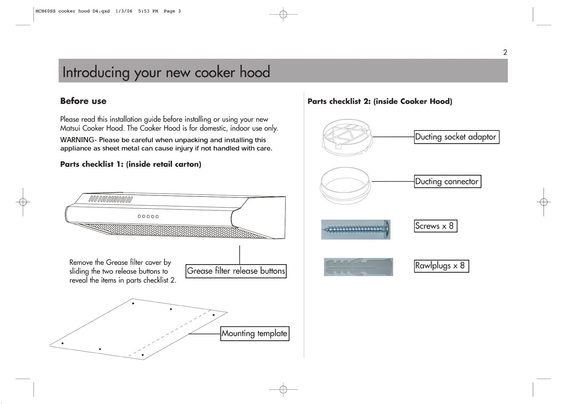
• The Cooker Hood must be installed
according to the manufacturer’s instructions.
Improper installation may result in injury or
damage, for which the manufacturer cannot
be held responsible.
• Check that the voltage (230 Volts AC)
printed on the rating label inside the
Cooker Hood corresponds to the mains
voltage in your home. If in doubt call a
qualified electrician.
• Never replace the electrical cable yourself.
An authorised service centre must replace
damaged electrical cables.
• Adaptors, multiple sockets and/or extension
leads must not be used.
• To avoid electrical shock, never touch the
Cooker Hood or plug with wet hands.
• Ventilation outlets on the Cooker Hood
should never be covered, as obstructions
may cause overheating or fire.
• Always disconnect the plug from the mains
supply before cleaning the Cooker Hood or
carrying out maintenance work.
Safety
WARNING!
It is hazardous for anyone other than
authorised service personnel to carry out
Servicing or repairs which involves the
removal of covers.
To avoid the risk of an electric shock do not
attempt to repair this appliance yourself.
Disposal
Old appliances still have some residual value.
An environmentally friendly method of
disposal will ensure that valuable raw
materials can be recovered and used again.
Up to date information concerning options for
disposing of your old appliance and
packaging from the new one can be obtained
from your local council office.
• Do not flambé under the Cooker Hood as
this may cause a fire hazard.
• The Cooker Hood is not intended for use
by young children or infirm persons.
• The risk of fire is increased if cleaning
instructions are not followed correctly.
Page 3
Page 4

Rear mounted or top mounted
The Cooker Hood can
be rear mounted by
fitting it to an
open area
of kitchen wall,
as shown in the
picture opposite.
Or top mounted
by fitting it to the
underside of a
kitchen cupboard,
as shown in the
picture opposite.
You may choose to install your Cooker Hood by:
a) external ventilation using ducting to extract
the ‘dirty’ air or:
b) internal ventilation, which re-circulates the
air, using a Charcoal filter.
For details of where to obtain either the ducting
or Charcoal filter, please contact the store from
which you purchased your Cooker Hood.
Extracted air
If it is being fitted to a kitchen wall which is
an outside wall (i.e. the other side of the wall
is in the open air) or to a wall which contains
an old chimney flue, the extracted air method
can be used. This is where the ‘dirty’ air from
the kitchen cooker is blown into the open air,
either up the chimney flue or through a hole
in the wall. This is the most effective way to
use the Cooker Hood. However, the air
extracted from the unit should not enter a
chimney or flue which is being used for
other appliances that use gas or other fuels.
Local regulations regarding chimney flues
must be adhered to.
Min
160mm
Filters
The Cooker Hood is supplied with a Grease filter.
This thin grease filter is fitted to the unit. It should
always be used as it traps grease from the
‘dirty’ air. Therefore, the Cooker Hood,
its ducting and chimney flue do not get
excessively greasy.
The Grease filter has to be cleaned and/or
replaced regularly, as explained later.
The Charcoal filter, which is not supplied,
contains charcoal that is capable of adsorbing
gasses containing smells.
Obviously, if you are using the Cooker Hood
as an extractor, it is not necessary to use this
filter, as all the smells go into the outside air.
If fitted, the Charcoal filter has to be replaced
regularly, as explained later.
Fixing height
The Cooker Hood should be fitted so that its
underside is a minimum of 700mm above the
surface of the cooker below.
Installation options
Re-circulated air
If it is being fitted to a kitchen wall which is an
inside wall (i.e. the other side of the wall is
another room of the house, or a neighbours
house) the re-circulated air method must be used.
This is where the ‘dirty’ air from the kitchen
cooker is passed through a Charcoal filter to
remove smells. The air is then re-circulated back
into the kitchen.
Min 700mm
3
Page 5

4
Power supply
Connect the Cooker Hood to an electrical
socket.
WARNING!
Always remember to disconnect from the mains
supply before cleaning and completing any
maintenance on the Cooker Hood.
Extracted air installation
If
you
are
fitting
will need the following items:
-
A minimum of 500mm of flexible ducting,
125mm in diameter.
- An external grille.
1 There is a ‘diverter switch’ inside the
Cooker Hood, which diverts the air so that
it leaves through one of the circular ducting
Sockets.
as shown in the picture below.
the unit to an outside wall you
Turn the switch to position B,
2 Decide whether you can make a hole
through an external wall directly behind
the Cooker Hood or whether you will have
to make a hole elsewhere.
The Cooker Hood is designed so that you
can choose whether to blow air out of its
rear side (horizontal discharge) or top side
(vertical discharge). Depending on your
choice, remove the partially cut disk
(knockout panel) from the top or rear of
the Cooker Hood. Insert a flat head
screwdriver under one edge and lever it
up. A pair of pliers may be required to
pull it free. Break all four attachment points
and it will come free. It can be discarded.
Be careful, it has very sharp edges!
A B
Page 6

Extracted air installation
7 Fit the Ducting connector into the Ducting
socket adaptor.
5
Two extra ‘security screws’ are used to ensure
the unit is secure and isn’t accidentally pushed
off the keyhole slots.
Screw the keyhole positioned screws into your
wall or kitchen cupboard so that the top
surface of the screw head is approximately
4mm from the surface you are screwing to.
If you are rear mounting the unit, drill all four
holes and fit the rawlplugs, but don’t fit the two
‘security screws’ until the unit is in place.
If you are top mounting the unit, drill all eight
holes, but don’t fit the four ‘security screws’
until the unit is in place.
5 Check that your fixings are correctly
located, by temporarily fitting the
Cooker Hood. If correct, remove the
protective film from each side of the unit.
6 Fit the Ducting socket adaptor in the hole
you made in the Cooker Hood when the
knockout panel was removed. Some of
the black plastic tabs of the adaptor
should be pushed through the hole, while
others remain above. This locks the
adaptor in place.
3 Make a 130mm hole through your
external kitchen wall in the appropriate
place. If you are using the top mounted
method of fixing you will have to use a
jigsaw to cut a 130mm diameter hole in
the kitchen cupboard.
It is recommend that a qualified person,
experienced in fitting Cooker Hoods,
is consulted before installation.
4 Use the card template supplied to mark
the position of the fixing screws.
If you are going to rear-mount the Cooker Hood,
the screws and rawlplugs supplied should only
be used in a (plastered) brick, breeze block or
blockwork wall. They are not suitable for lath
and plaster walls or stud and plasterboard
walls. Consult a qualified builder for advice on
fixing into these types of walls. If you are top
fixing the Cooker Hood to a kitchen cupboard,
use the screws provided.
The keyhole slots are designed so the
Cooker Hood locates over the larger area of
the hole and is then pushed back, or dropped
down onto the smaller area of the hole.
Ducting socket adaptor
Ducting connector
Page 7

8 Fit the flexible ducting into the Ducting
socket adaptor.
Fit the unit into position. Tighten the
screws if necessary. Feed the flexible
ducting through the hole in the wall.
9 Fit the external grille.
10 The Charcoal filter is designed to remove
‘odours’ from dirty air. As the ‘odours’ are
being extracted to the outside air it is not
necessary to fit the Charcoal filter.
11 Fit the main filter panel by locating the
rear pins in their slots and pressing the
release buttons. It will click into place.
12 Connect the Cooker Hood to the power
supply, as mentioned earlier in the guide.
Ducted air installation
1 The Cooker Hood must be fitted so that it
protrudes 160mm from the cupboard it is
being fitted to (see page 2). This is to
allow the re-circulated air to escape
through the grille in the top of the unit.
2 Use the card template supplied to mark
the position of the fixing screws.
The keyhole slots are designed so the
Cooker Hood locates over the larger area of
the hole and is then pushed back, onto the
smaller area of the hole. Two extra ‘security
screws’ are used to ensure the unit is secure and
isn’t accidentally pushed off the keyhole slots.
Screw the keyhole positioned screws into your
wall or kitchen cupboard so that the top
surface of the screw head is approximately
4mm from the surface you are screwing to.
If you are top mounting the unit, drill all eight
holes, but don’t fit the four ‘security screws’
until the unit is in place.
3 Check that your fixings are correctly
located, by temporarily fitting the
Cooker Hood. If correct, remove the
protective film from each side of the unit.
4 Fit the unit into position. Tighten the
screws if necessary.
5 Fit the Charcoal filter (not supplied –
please contact the store from which you
purchased your Cooker Hood) by first
lift
the filter up into the Cooker Hood,
aligning the posts with the locating holes
on the filter. Turn the filter clockwise
to lock it into position.
6 Fit the main filter panel by locating the
rear pins in their slots and pressing the
release buttons. It will click into place.
7 Connect the Cooker Hood to the power
supply, as mentioned earlier in the guide.
Re-circulated air installation
6
Page 8

7
There are five control buttons on the front of the
Cooker Hood.
0 – off
– varying degrees of
air extraction: =Low, =High
•
•
•••
•• •••
Light on or off
It is recommended that the Cooker Hood
remains switched on for a period of
10-15 minutes after cooking has finished, to
ensure all ‘dirty’ air is re-circulated or extracted.
In use
1 Slide the two Grease filter cover release
buttons on the underside of the
Cooker Hood inwards. The filter cover
will be released downwards.
2 The thin grease filter is removed
by releasing it from the U-shape metal hangers.
Please refer the steps below:
3 Wash the filter in warm water and mild
detergent. Open it out flat and leave it to
dry. Don’t twist it excessively when wringing
it out and don’t spin dry it. Make sure it is
completely dry before replacing it.
Before carrying out any maintenance switch
off the Cooker Hoods power supply at the
mains, and unplug.
Cleaning
Clean the outside of the unit with a damp
cloth and a small amount of washing up liquid.
Use special stainless steel cleaner on stainless
steel surfaces.
Don
’t use solvents or abrasives as they may
damage the surfaces of the unit.
Changing the filters
Charcoal filter
The Charcoal filter should be changed after a
period of use. How often you replace it
depends on how often you cook, but as a
rough guide it should be changed every
six months.
Grease filter
The Grease filter should be washed
periodically. A build up of grease may cause
a fire hazard.
Maintenance
, ,
Squeeze the side to release the U-shape hanger.
1
Lift the hangers out from the filter cover’s edge.
2
Page 9

Maintenance and Troubleshooting
Changing the internal light
Allow the Cooker hood to cool for at least
30 minutes after use before changing the
light bulb.
1 Slide the two Grease filter cover release
buttons off the underside of the cooker
hood inwards, The filter cover will be
released downwards.
2 Remove the old bulb by unscrewing it in
an anti-clockwise direction.
3 Replace with a new bulb (230V/40w)
by screwing it in a clockwise direction.
Make sure it is securely inserted in the
bulb holder. Kindly note that your Cooker
hood is fitted with 2x40W (max.) bulbs.
The Cooker hood is not working
• Check it is plugged in and switched on.
• Check that the fuse in the plug has
not blown.
• Plug in another appliance, such as a
lamp, to see if the socket is working.
Servicing
Only an authorised, qualified technician
should perform repairs and maintenance of
the appliance.
MSH601W MSH601BLK & MSH601SS
MSH601WE MSH601BLKE & MSH601SSE
230
50
200
6.1
14x60x50
2x40W Max.
4 Replace the filters.
Page 10

2006/95/EC
2004/108/EC
Visit Partmaster.co.uk today for the easiest way to
buy electrical spares and accessories.
With over 1 million spares and accessories available
we can deliver direct to your door the very next day.
Visit www.partmaster.co.uk
or call
0870 6001 338
(UK customers only)
Calls charged at National Rate.
Cod:0103072956
 Loading...