

Page 1

User Manual
DEALER: This manual MUST be given to the user of the product.
USER:
BEFORE using this product, read this manual and save for
future reference.
Invacare® Matrx® PB Elite
Model Numbers PBE, PBE-FB and EDB
1 General
1.1 Symbols
Signal words are used in this manual and apply to hazards or unsafe practices which could result in personal injury or property damage. See the information below for definitions of the signal words.
WARNING
1.2 Overview Important Information
The best way to avoid problems related to pressure sores is to understand their causes and your role in a skin management program.
Your therapist and physician should be consulted if you have questions regarding individual limitations and needs.
All cushions should be selected carefully. Working with your therapist and physician is the best way to assure that a cushion choice matches your individual needs.
As the needs of the individual become more complex, cushion evaluation becomes more important.
Invacare Matrx Elite
The Invacare Matrx Elite back is contoured to provide precise orientation within the wheelchair for optimal postural support. The foam is oversized to provide extra comfort and protection.
The Invacare Matrx Elite back includes a movable foam lumbar pad that can be installed/inserted behind
the existing foam cushion to provide additional positioning capability. Refer to Lumbar Support (Optional)
on page 10 for instructions on how to insert and adjust your lumbar support.
Outer Cover
The outer cover is made of a mesh material that is moisture resistant and breathable. Regular cleaning and inspection of the outer cover is recommended. Refer to Care and Maintenance on page 10.
Warning indicates a potentially hazardous situation which, if not avoided, could result in death or serious injury.
CAUTION
Caution indicates a potentially hazardous situation which, if not avoided, may result in property damage or minor injury or both.
Gives useful tips, recommendations and information for efficient, trouble-free use.
Part No 1171724 1 Invacare® Matrx® PB Elite
Page 2

2 Safety
Check ALL parts for shipping damage. If shipping damage is noted, DO NOT use. Contact
carrier/dealer for further instruction.
2.1 Transporting the Client Within a Wheelchair Fitted with a Matrx Back in a Motor Vehicle
The following guidelines should be made available to all parties who are responsible for the transportation of the client, such as schools and transport providers.
Wherever practicable the client should be transferred out of the wheelchair into a vehicle seat and use a lap and diagonal seat belt or an appropriate child safety seat.
The Matrx back has been dynamically tested and meets the requirements of ISO 16840-4 and Section 20,
ANSI/RESNA WC/Volume 4 “Wheelchair Seating Systems for Use in Motor Vehicles”. A Surrogate
Wheelchair Base (SWCB) and a Hybrid III Midsize-Adult Male Anthropomorphic Test Device were used
in a forward facing frontal impact test. The SWCB was secured by a four-point, strap type wheelchair tiedown and the occupant restraint was a vehicle anchored lap and diagonal occupant restraint system.
Matrx backs should only be used in conjunction with wheelchairs that comply with the performance requirements of ANSI WC19 or ISO 7176-19.
Before Entering the Vehicle Check the Following:
Matrx Back - must be securely fastened into the wheelchair as described in the user manual.
Posture Belts and Harnesses - should remain fitted during transportation, although they are designed to
provide postural support only, they are not intended for safety during transportation.
Head Support - must be securely fitted and correctly adjusted close to the rear of the client’s head during
transportation, in order to reduce the risk of whiplash injuries.
The Wheelchair Tie-down and Occupant Restraint System (WTORS)
Wheelchair Tie-down - The wheelchair must be securely tied down within the vehicle, in a forward facing
position, in accordance with the wheelchair and tiedown manufacturers instructions.
Occupant Restraint - A suitable occupant restraint system must also be fitted in accordance with the
manufacturer’s instructions. A minimum is a lap and diagonal belt (lap belts on their own are not suitable).
Restraints that loop over the shoulder and anchor to the vehicle floor should be avoided where possible,
as they can cause a heavy downward load through the client during an impact, the preferred type anchor
above and behind the shoulder as with a car seat belt. The lap section of the belt should fit snugly over
the pelvis of the client and should not be able to ride up to the abdominal area. The upper torso section
of belt should be in contact with the client’s chest and fit over the shoulder(s), while not cutting into the
neck or slipping off the shoulder(s).
If the wheelchair and Matrx back are to be transported unoccupied, the wheelchair should be tied
down with suitable equipment according to the manufacturer’s instructions. If the equipment is to
be dismantled for transportation, ensure that all parts are secured safely within the vehicle.
2.2 Intended Use
The Invacare Matrx Elite back is designed to provide precise orientation within the wheelchair for optimal postural support.
Invacare® Matrx® PB Elite 2 Part No 1171724
Page 3

2.3 General Warnings
WARNING
DO NOT USE THIS PRODUCT OR ANY AVAILABLE OPTIONAL EQUIPMENT WITHOUT
FIRST COMPLETELY READING AND UNDERSTANDING THESE INSTRUCTIONS AND
ANY ADDITIONAL INSTRUCTIONAL MATERIAL SUCH AS OWNER’S MANUALS, SERVICE
MANUALS OR INSTRUCTION SHEETS SUPPLIED WITH THIS PRODUCT OR OPTIONAL
EQUIPMENT. IF YOU ARE UNABLE TO UNDERSTAND THE WARNINGS, CAUTIONS OR
INSTRUCTIONS, CONTACT A HEALTHCARE PROFESSIONAL, DEALER OR TECHNICAL
PERSONNEL BEFORE ATTEMPTING TO USE THIS EQUIPMENT - OTHERWISE, INJURY OR
DAMAGE MAY OCCUR.
ACCESSORIES WARNING
Invacare products are specifically designed and manufactured for use in conjunction with Invacare accessories. Accessories designed by other manufacturers have not been tested by Invacare and are not recommended for use with Invacare products.
INSTALLATION WARNING
The procedures in this manual should be performed by a qualified technician.
After any adjustments, repair or service and before use, make sure that all attaching component
parts are secure.
DO NOT install the Invacare Matrx Elite assembly onto back canes with an outside diameter
greater than 1-inch or less than 3/4-inch. Otherwise, injury or damage may occur.
The mounting position of the Invacare Matrx Elite is directly related to the chair's stability. When
the Invacare Matrx Elite is added to a TILT and/or RECLINING chair, it may cause a decrease in
the chair's stability. It may be necessary to reposition the FRONT CASTERS, REAR WHEELS,
BACK ANGLE, TILT-IN-SPACE, RECLINE POSITION and/or SEAT DEPTH before use. Use
extreme caution when using a new seating position.
When a Matrx Elite is added to a TILT and/or RECLINING chair, a RIGIDIZER BAR or CROSSBAR must be present to stabilize the back canes.
Ensure the Invacare Matrx Elite is properly secured to the wheelchair before using. Otherwise injury or damage may occur.
WARNING
Skin condition should be checked very frequently after the installation of any new seating system.
Your therapist and physician should be consulted if you have any questions regarding individual
limitations and needs.
Working with your therapist, physician, and equipment supplier is the best way to assure that a
seating choice matches your individual needs.
As the needs of the individual become more complex, the seating evaluation becomes more
important.
Part No 1171724 3 Invacare® Matrx® PB Elite
Page 4
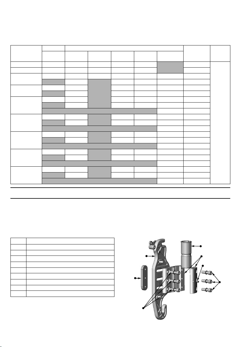
2.4 Weight Limitation and Model Numbers
Back
Mounting
Plate
Cane
Clamp
Nut
Plate
Depth/Recline
Adjustment
Screws
Cane Insert
Cane Clamp
Set Screw
Cane
Clamp
Screws
Refer to the chart for the weight limitation and stock model numbers.
Configured model numbers are: PBE and EDB
PBE = Matrx Elite Back, PBE-FB = Matrx Elite Full Back, EDB = Matrx Elite Deep Back
Grey = size not available
WIDTH HEIGHT CONTOUR
10 IN
(25 CM) 12 in (30 cm) PBE1210 PBE1212 PBE1214 PBE1216 PBE1218 13 in (33 cm) PBE1310 PBE1312 PBE1314 PBE1316 PBE1318 3 in (8 cm) 14 in (36 cm) PBE1410 PBE1412 PBE1414 PBE1416 PBE1418 PBE1420 3 in (8 cm)
15 in (38 cm) PBE1510 PBE1512 PBE1516 PBE1518 PBE1520 3 in (8 cm)
16 in (41 cm) PBE1610 PBE1612 PBE1616 PBE1618 PBE1620 3 in (8 cm)
17 in (43 cm) PBE1710 PBE1712
18 in (46 cm) PBE1810 PBE1812
19 in (48 cm) PBE1910 PBE1912
20 in (51 cm) PBE2010 PBE2012
12 IN
(30 CM)
EDB1412 EDB1416 EDB1418 EDB1420 6 in (15 cm)
EDB1512 EDB1516 EDB1518 EDB1520 6 in (15 cm)
EDB1612 EDB1616 EDB1618 EDB1620 6 in (15 cm)
EDB1712 EDB1716 EDB1718 EDB1720 6 in (15 cm)
EDB1812 EDB1816 EDB1818 EDB1820 6 in (15 cm)
EDB1912 EDB1916 EDB1918 EDB1920 6 in (15 cm)
EDB2012 EDB2016 EDB2018 EDB2020 6 in (15 cm)
14 IN
(36 CM)
16 IN
(41 CM)
PBE1716 PBE1718 PBE1720 3 in (8 cm)
PBE1816 PBE1818 PBE1820 3 in (8 cm)
PBE1916 PBE1918 PBE1920 3 in (8 cm)
PBE2016 PBE2018 PBE2020 3 in (8 cm)
18 IN
(46 CM)
20 IN
(51 CM)
PBE1620-FB 3 in (8 cm)
PBE1720-FB 3 in (8 cm)
PBE1820-FB 3 in (8 cm)
PBE1920-FB 3 in (8 cm)
PBE2020-FB 3 in (8 cm)
DEPTH
3 in (8 cm) 300 lbs
WEIGHT
LIMIT
(136 kg)
3 Setup
3.1 Hardware Kit Contents
If any of the hardware is missing or misplaced, please contact our customer service department
and arrangements will be made to send you the necessary replacements.
Canada: 866-748-7943 USA: 888-433-6818
3/4” (19 mm) cane inserts are available from Motion Concepts upon request.
QTY DESCRIPTION
2 Back Mounting Plates 2 Cane Clamps 2 Cane Inserts (1” (25 mm)) 2 Cane Inserts (7/8” (22 mm)) 6 Depth/Recline Adjustment Screws 6 Cane Clamp Screws 2Set Screws 2 Cane Clamp Nut Plates 4 Long Mounting Pins (optional)
3.2 Tools Required
Wrenches: 7/8” (22 mm) Phillips Screwdriver Allen Keys: (provided) Tape Measure/Ruler Utility Knife/Scissors
Invacare® Matrx® PB Elite 4 Part No 1171724
Page 5
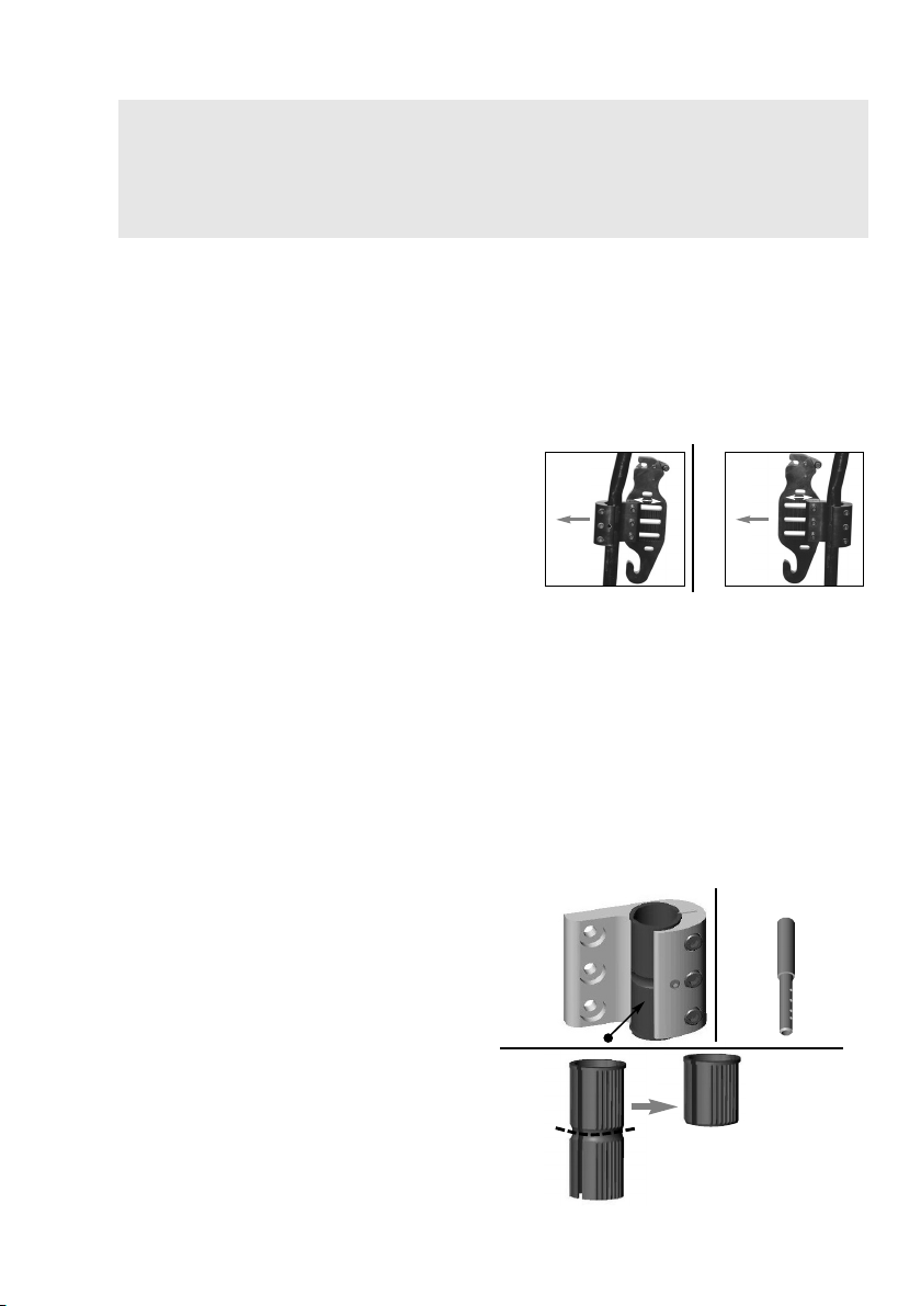
3.3 Before Installation
Front of Wheelchair
A
B
Mounting plate in rearmost back
position (maximized seat depth)
Mounting plate in
forwardmost back
position
Front of Wheelchair
Plastic Insert
A
B
The plastic insert may be cut if
the cane clamp is secured at
the junction of 2 different
diameter back posts.
PBCR
Mounting Configuration
WARNING
The mounting plates are shipped pre-assembled on the cane clamps in the rearmost mounting configuration. This maximizes the seat depth on the wheelchair seat (up to a maximum 2.5” (64 mm) rearward offset - see image A).
By changing the orientation of the mounting plates on the cane clamps, the assembly can be reconfigured* to provide a more forward mounting position for the back if desired (up to a maximum 2.5” (64 mm) forward offset - see image B).
*To reconfigure a mounting plate/cane clamp to
the forwardmost orientation:
1. Detach the mounting plate from the cane clamp
2. Rotate the cane clamp 180° and re-fasten it to
3. Install cane clamp as illustrated in image B.
When establishing the mounting position for the Invacare Matrx Elite, ensure the stability of the wheelchair is not compromised.
Adjusting the forward and aft position of the backrest will alter the user’s center of gravity within
the wheelchair. A recessed back position can significantly reduce the rearward stability of the
wheelchair. Similarly, a more forward back position will reduce the wheelchair’s forward stability.
Each mounting plates is also designed to provide 1.5” (38 mm) of fore and aft adjustment
relative to the cane clamp
(3 screws);
mounting plate;
Accommodating Back Cane Size
On some wheelchairs, there may be an uneven seam along the back posts where a smaller
diameter tube is inserted into a larger diameter tube. If the cane clamps must be mounted over
this seam, the plastic inserts may be cut in half to allow the clamp to fasten securely onto the back
posts (see image B).
For wheelchairs with short back canes, it may be necessary to install Matrx PB Cane
Replacements (PBCR’s). The PBCR’s are designed to replace existing push handles or cane
extensions
onto the replacement back canes in order to allow proper installation of the Invacare Matrx Elite.
Cane replacements are available from Motion Concepts (part#-TRX2810).
• 1” (25 mm) back cane - Cane clamps are
installed without plastic inserts.
• 7/8” (22 mm) back cane - Requires 7/8” (22
mm) plastic inserts (provided)
• 3/4” (19 mm) back cane - Requires 3/4” (19
mm) plastic inserts*
*3/4” (19 mm) inserts are available from
Motion Concepts upon request.
on standard 1” (25 mm) back posts. The cane clamps can be mounted directly
Part No 1171724 5 Invacare® Matrx® PB Elite
Page 6
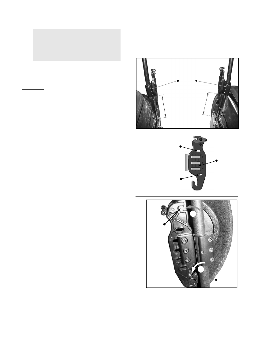
3.4 Installing the Invacare Matrx Elite
1
2
Cane
Clamps
Install cane clamps at equal
heights and parallel to each
other.
Front view of wheelchair with
back removed
Upper
Adjustment
Slot
Mounting
Plate
Lower
Adjustment
Slot
Upper
Mounting
Pin
Lower
Mounting
Pin
A
B
Installing the Mounting Plates
WARNING
1. Remove existing wheelchair back upholstery (if
2. Establish the desired mounting plate set-
3. Loosen cane clamp screws (x3) and loosely
4. Starting on one side, position the cane clamp at
5. From a fixed point on the wheelchair (e.g. seat
6. To install the Invacare Matrx Elite onto the
The installation hardware provided is high strength and tested for durability. DO NOT substitute hardware. Use only the hardware supplied.
applicable).
up/configuration for the user. Refer to Before
Installation on page 5.
install the cane clamp (with mounting bracket)
onto each back post. (Install plastic inserts if
required).
the desired height on the back post and tighten
the clamp screws enough to hold it in place.
Clamps and set screws will be fully tightened
after the back is installed and all final adjustments
have been made.
frame) measure the exact height of the installed
cane clamp assembly, and install the second cane
clamp at the same height on the opposite back
post - see image A on page 7. Ensure the cane
clamps/mounting plates are mounted parallel
with each other.
mounting plates:
A. Slide the lower mounting pins into the
Additional upper and lower adjustment
slots are provided on the mounting
plate to allow alternate mounting
heights if obstacles are encountered.
Using these alternate mounting slots will
increase or decrease the back height by
7/8” (22 mm). These alternate slots will
limit the range of available depth and/or
recline angle adjustment.
hooked slots at the bottom of each
mounting plate (see image B).
B. With the lower pins in place, lock/snap
the upper mounting pins into the latch
mechanism at the top of the mounting
plates.
Invacare® Matrx® PB Elite 6 Part No 1171724
Page 7
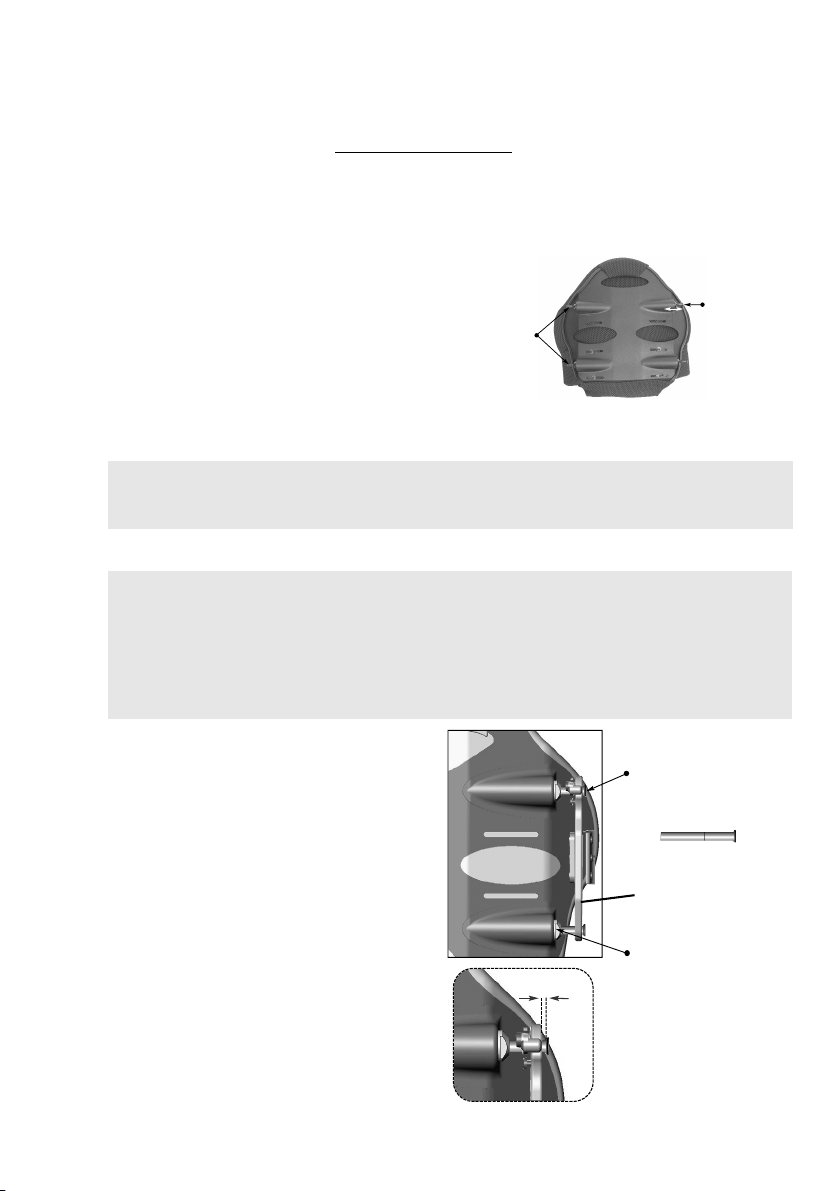
Mounting Pin Configurations/Setup
Rear View
Mounting
Pins (x 4)
Adjustable
Pin Depth
Standard
Mounting Pin
Flange Nut
Back Pan
1/8” (3 mm)
min. gap
(optional)
Long Mounting Pin
Mounting Plate
Invacare Matrx Elite backs are available in a range of widths (12” (31 cm) - 20” (51 cm)) and 6
different heights (10” (26 cm); 12” (31 cm); 14” (36 cm); 16” (41 cm); 18” (46 cm) and 20” (51
cm)). Due to variances that exist between different wheelchair manufacturers, the depth of the
mounting pins may require some adjustment to properly fit the Invacare Matrx Elite onto the
wheelchair back posts. Refer to Mounting Pin Adjustment on page 7. Two sets of mounting pins
are supplied with every Invacare Matrx Elite (standard pins and long pins). The standard pins are
installed at the factory and are suitable for most typical wheelchair configurations. The long pins
are designed to allow installation onto back posts that are up to 1” (25 mm) wider than the width
of the actual backrest.
*Elite back widths are offered in 1” (25 mm) increments).
Example: for a 16" (41 cm) Invacare Matrx Elite:
16" (41 cm) wheelchair seat frame (back post)
width = standard pins
17" (43 cm) wheelchair seat frame (back post)
width = long pins
When the narrowest setting is used for the back,
the depth/recline range will be less than in wider
positions.
Extended Mounting Pins (EMP) are available (sold separately) to allow interfacing of our Invacare Matrx Elite backs onto wheelchair seat frames up to 2” (5 cm) wider than the actual back width.
CAUTION
* EMP’s are only for use with our standard back sizes (for up to 300lb (136 kg) weight capacity); EMP’s are not recommended for use in tilt applications.
Mounting Pin Adjustment
CAUTION
1. With the back secured in place on the
2. Remove the backrest from the wheelchair and
3. Adjust the mounting pin depth (clockwise to
4. Re-tighten each flange nut to secure the pins in
Improper pin set-up may cause damage to the back pan and/or the mounting plates. Ensure sufficient spacing is provided between the mounting plates and the mounting pins (a min. gap of 1/8” (3mm) is recommended).
Ensure flange nuts are fully tightened; Failure to do so may cause damage/cracking in the back pan.
Ensure pins do not rotate when tightening the flange nuts. NEVER use Loctite® on mounting pin
hardware.
wheelchair, determine the amount of
adjustment required for each mounting pin (see
figure).
use a wrench to loosen the flange nut on each
pin that requires adjustment. If necessary,
replace the standard mounting pins with long
mounting pins.
shorten/counter-clock wise to lengthen) so that
a minimum gap of 1/8” (3mm) exists between
the top of the pin and the mounting plate.
place.
Part No 1171724 7 Invacare® Matrx® PB Elite
Page 8
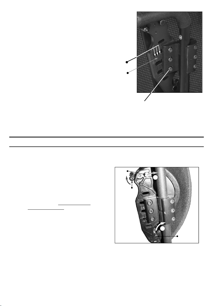
Installing the Back
.
*Use score
lines to make
symmetrical
adjustments
on the left
and right
mounting
plates.
Score
Lines
Depth/Recline Screws
2
1
Upper Mounting Pin
Lower
Mounting
Pin
Release
Lever
1. Verify that the overall fit and alignment of the back is correct (make adjustments as needed).
2. Fully secure the cane clamp screws onto both back posts, and tighten the set screws to ensure the mounting plates do not slip or rotate.
3. To best determine the optimal depth and recline
settings for the back, the user should be seated
in the wheelchair. While seated, loosen the
depth/recline screws on the mounting plates and
adjust the back to the desired depth and recline
angle. Re-tighten all screws to lock the back in
position.
Ensure that the depth/recline
adjustment for the back is made
symmetrically* on the left and right
mounting plates.
The vertical score lines on the mounting
plates are designed as a point of
reference to assist with symmetrical
mounting (see image). Since the back
can be mounted in a rotated (reclined)
position if desired, it will not always be
mounted parallel with these vertical
lines.
4 Usage
4.1 Disengaging the Back from the Wheelchair
1. Perform one of the following:
• No Cord Release Mechanism -
Simultaneously lift the release levers
(left and right) to unlock the latch
mechanism and release the upper pins
from the mounting plates. Refer to the
figure.
• Cord Release Mechanism - Lift cord
upward to unlock/open the release
levers. Refer to One-Hand Cord
Release Mechanism on page 9.
2. Lift entire backrest up and forward to disengage the lower pins from the lower slots in the mounting plates.
Invacare® Matrx® PB Elite 8 Part No 1171724
Page 9
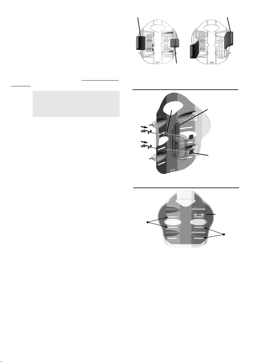
4.2 Lateral Supports (Optional)
Standard Lateral (large)
Standard Lateral (small)
Offset Lateral
Offset laterals may be mounted to the
back pan in either orientation (as
shown) to provide extended support.
Lateral Support
Bracket
Spacer
Spacers are only required when
using the upper slot on the back pan.
Front
Backing Plate
Lower
Mounting
Slots
Upper
Mounting
Slots
Rear
3” (76 mm)
Lower mounting slots not available
on 10” (26 cm) or 12” (31 cm) high
Invacare Matrx Elite backs.
Lateral Pads are available from Motion Concepts
as an option for additional lateral support. Lateral
Pads are offered in small, large and offset styles
(see Figure). Mounting slots in the back shell and
the lateral support brackets allow for adjustment
both vertically and laterally. Upper and lower
mounting slots are provided on the back pan for
an even greater range of adjustment. Lateral
Supports may be further customized by carefully
bending* the lateral to a more desirable contour/
position for the client. Refer to Installing Lateral
Supports.
WARNING
*For best results and to prevent damage, the lateral supports must be removed from the back pan prior to bending
Installing Lateral Supports
1. Pull up the bottom of the cover (release hook and loop fasteners) to expose the mounting slots/channels in the back pan.
2. Determine the desired mounting height/orientation for the lateral pads (upper or lower mounting slot position).
3. If applicable, carefully bend the lateral support(s) to the desired contour (prior to installation).
4. Loosely install the lateral supports onto the back pan using the hardware provided.
Hardware can be installed in either
orientation on the back pan (with the
backing plates located on the inside
or outside of the back pan). The
standard mounting orientation is
shown at right.
5. Adjust laterals to the desired position via the mounting slots on the backpan and via the slots in the lateral support bracket. Secure each lateral support into place.
6. Re-attach the back cover via the hook and loop fasteners.
4.3 One-Hand Cord Release Mechanism
1. Thread the nylon cord through the holes in the latch mechanism at the top of the left and right mounting plates (see image A)
2. Install the cord lock mechanism onto the cord (see image B). Press the button to open the lock mechanism and slide the two open ends of the nylon cord through the opening.
3. With the back properly installed on the wheelchair, adjust the cord length so that it hangs at
approximately a 45° angle along the back pan (this allows the release mechanism to operate more
effectively). If necessary, cut/remove excess cord to eliminate any risk of entanglement. Once
adjusted, combine the loose cord ends into a single knot to prevent the cord-lock from slipping.
Part No 1171724 9 Invacare® Matrx® PB Elite
Page 10
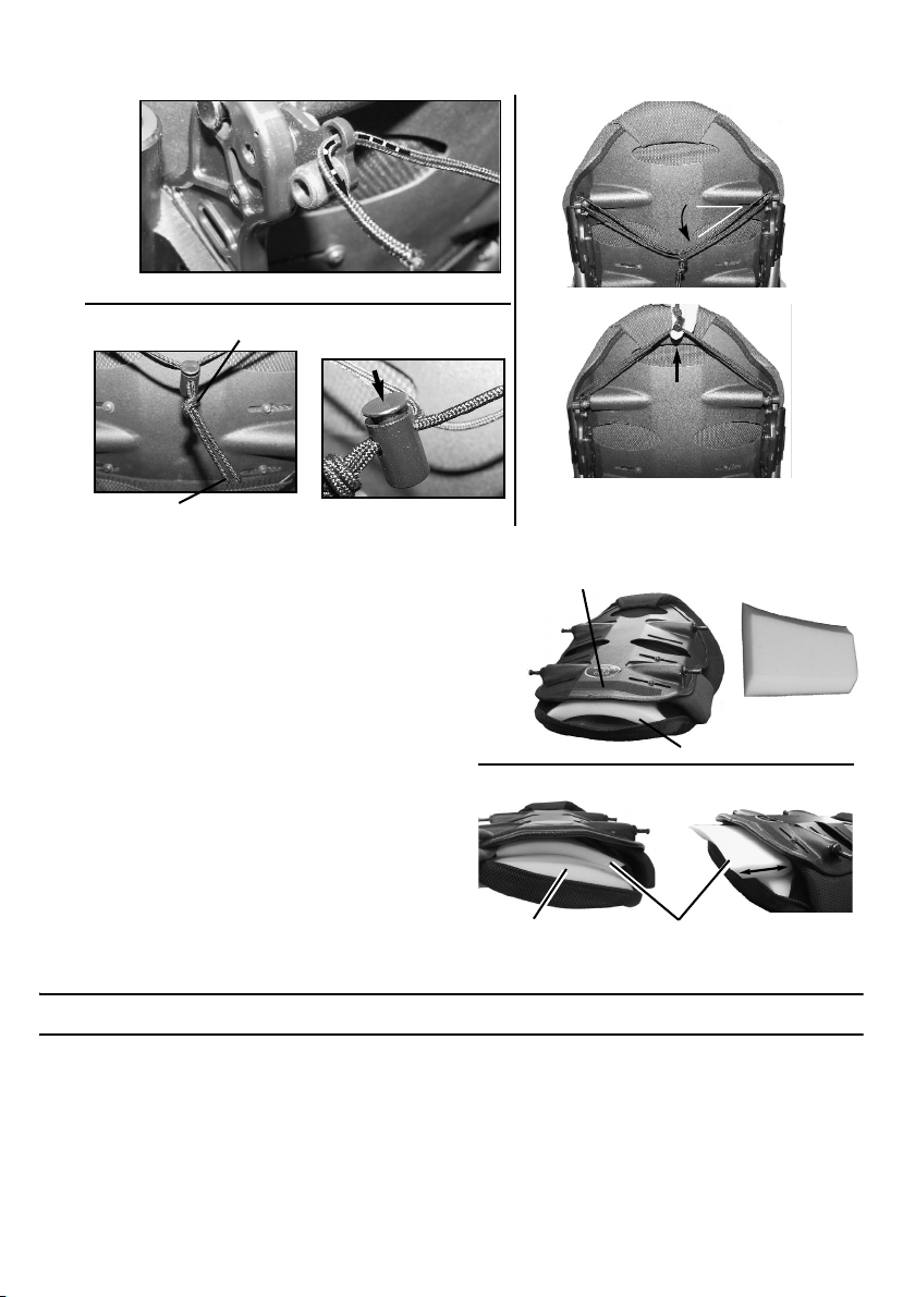
If the cord length was modified, carefully melt the ends of the cord to prevent fraying.
Thread cord through the latch mechanism.
A
B
Tie a knot using both
cord ends.
Melt cord ends to prevent fraying.
Press button to
open/adjust.
Cord
Lock
45°
Installed Back
Lift cord to
release back
cushion.
Hook and loop fastening strip
Foam Cushion
Front
Lumbar
Support
B
A
Lumbar Support
Foam Cushion
4.4 Lumbar Support (Optional)
The Lumbar Support is a pre-
fabricated foam insert that provides
lower back support for additional
comfort. The position of the lumbar
insert can be adjusted inside the
Invacare Matrx Elite cover, or it may
be removed if no lumbar support is
desired
Lumbar Support Adjustment
1. To access the Lumbar Support, open the hook and loop fastening strips on the outer cover at the bottom rear of the back pan.
2. The foam lumbar support/ insert is installed inside the Invacare Matrx Elite cover between the foam back cushion and the back pan (see image B)
3. The lumbar support can be adjusted manually to any desired height/position.
4. Refasten the cover onto the back pan.
5 Care and Maintenance
5.1 Cleaning
The cover may be easily wiped down with a damp cloth when necessary. The cover can be removed for
laundering or providing access to the inside of the back for modification. Carefully remove the cover by
releasing the hook and loop fasteners along the top and bottom edge and inside of the back shell. Remove
the inner foam cushion from the cover prior to laundering.
Invacare® Matrx® PB Elite 10 Part No 1171724
Page 11

5.2 Inspection
WARNING
Visually inspect parts including hardware, brackets, upholstery materials, foams (if accessible), and plastics, for deformation, corrosion, breakage, wear or compression.
Check ALL fasteners weekly to ensure that mechanical connections and attaching hardware are tightened securely - otherwise injury or damage may occur.
DO NOT continue to use this product if problems are discovered. Corrective maintenance can be performed at or arranged through your equipment supplier.
6 After Use
6.1 Reuse
WARNING: Risk of Injury
Always have a dealer inspect the product for damage before transferring the product to a different user. If any damage is found, DO NOT use the product. Otherwise injury may occur.
7 Warranty
PLEASE NOTE: THE WARRANTY BELOW HAS BEEN DRAFTED TO COMPLY WITH FEDERAL LAW APPLICABLE TO
PRODUCTS MANUFACTURED AFTER JULY 4, 1975.
This warranty is extended only to the original purchaser/user of our products.
This warranty gives you specific legal rights and you may also have other legal rights which vary from state to state.
Invacare/Motion Concepts warrants this product to be free from defects in materials and workmanship for two years of use by
original purchaser. This warranty does not apply to punctures, tears or burns, nor to the removable cushion cover. If within such
warranty period any such product shall be proven to be defective, such product shall be repaired or replaced, at
Invacare's/Motion Concepts’ option, with refurbished or new parts. This warranty does not include any labor or shipping charges
incurred in replacement part installation or repair of any such product. Product repairs shall not extend this warranty - coverage
for repaired product shall end when this limited warranty terminates. Invacare's/Motion Concepts’ sole obligation and your
exclusive remedy under this warranty shall be limited to such repair and/or replacement.
For warranty service, please contact the dealer from whom you purchased your Invacare/Motion Concepts product. In the event
you do not receive satisfactory warranty service, please write directly to Invacare/Motion Concepts at the address on the back
cover. Provide dealer's name, address, model number, the date of purchase, indicate nature of the defect and, if the product is
serialized, indicate the serial number.
Invacare Corporation/Motion Concepts will issue a return authorization. The defective unit or parts must be returned for
warranty inspection using the serial number, when applicable, as identification within thirty (30) days of return authorization date.
DO NOT return products to our factory without our prior consent. C.O.D. shipments will be refused; please prepay shipping
charges.
LIMITATIONS AND EXCLUSIONS: THE WARRANTY SHALL NOT APPLY TO PROBLEMS ARISING FROM NORMAL
WEAR OR FAILURE TO ADHERE TO THE ENCLOSED INSTRUCTIONS. IN ADDITION, THE FOREGOING
WARRANTY SHALL NOT APPLY TO SERIAL NUMBERED PRODUCTS IF THE SERIAL NUMBER HAS BEEN REMOVED
OR DEFACED; PRODUCTS SUBJECTED TO NEGLIGENCE, ACCIDENT, IMPROPER OPERATION, MAINTENANCE OR
STORAGE; OR PRODUCTS MODIFIED WITHOUT INVACARE'S/MOTION CONCEPTS’ EXPRESS WRITTEN CONSENT
INCLUDING, BUT NOT LIMITED TO: MODIFICATION THROUGH THE USE OF UNAUTHORIZED PARTS OR
ATTACHMENTS: PRODUCTS DAMAGED BY REASON OF REPAIRS MADE TO ANY COMPONENT WITHOUT THE
SPECIFIC CONSENT OF INVACARE/MOTION CONCEPTS; PRODUCTS DAMAGED BY CIRCUMSTANCES BEYOND
INVACARE'S/MOTION CONCEPTS’ CONTROL; PRODUCTS REPAIRED BY ANYONE OTHER THAN AN
INVACARE/MOTION CONCEPTS DEALER, SUCH EVALUATION SHALL BE SOLELY DETERMINED BY
INVACARE/MOTION CONCEPTS.
THE FOREGOING WARRANTY IS EXCLUSIVE AND IN LIEU OF ALL OTHER EXPRESS WARRANTIES, IF ANY,
INCLUDING THE IMPLIED WARRANTIES OF MERCHANTABILITY AND FITNESS FOR A PARTICULAR PURPOSE.
IT SHALL NOT EXTEND BEYOND THE DURATION OF THE EXPRESSED WARRANTY PROVIDED HEREIN AND THE
REMEDY FOR VIOLATIONS OF ANY IMPLIED WARRANTY SHALL BE LIMITED TO REPAIR OR REPLACEMENT OF THE
DEFECTIVE PRODUCT PURSUANT TO THE TERMS CONTAINED HEREIN. INVACARE/MOTION CONCEPTS SHALL
NOT BE LIABLE FOR ANY CONSEQUENTIAL OR INCIDENTAL DAMAGES WHATSOEVER.
THIS WARRANTY SHALL BE EXTENDED TO COMPLY WITH STATE/PROVINCIAL LAWS AND REQUIREMENTS.
Part No 1171724 11 Invacare® Matrx® PB Elite
Page 12

Invacare
USA
One Invacare Way
Elyria, Ohio USA
44036-2125
440-329-6000
800-333-6900
www.invacare.com
Canada
570 Matheson Blvd. E Unit 8 Mississauga Ontario L4Z 4G4 Canada 800-668-5324
Motion Concepts
USA
700 Ensminger Rd. Suite 112 Tonawanda, NY 14150 888-433-6818
www.motionconcepts.com
Canada
84 Citation Dr. Concord, Ontario L4K 3C1 905-695-0134
© 2011 Motion Concepts. All rights reserved. Republication, duplication or
modification in whole or in part is prohibited without prior written permission
from Motion Concepts. Trademarks are identified by ™ and ®. All trademarks are
owned by or licensed to Motion Concepts unless otherwise noted.
Loctite is a registered trademark of Henkel Corporation.
Part No 1171724 Rev A - 02/11
 Loading...