

Master Forge 3218ltn Owner's Manual

1
Lowes.com/masterfor
g
e
ATTACH YOUR RECEIPT HERE
Serial Number Purchase Date
Questions, problems, missing parts? Before returning to your retailer, call our
customer service department at 1-800-963-0211, 8:00 a.m. to 6:00 p.m., EST,
Monday-Thursday, 8:00 a.m. to 5:00 p.m., EST, Friday.
5-BU
RNER GAS GRILL
ITEM #0006554
MODEL #3218LTN
Español p. 53
Master Forge & M Design® is a registered
trademark of LF, LLC. All rights reserved.
WARNING
1. Do not store or use gasoline or
other flammable vapors and
liquids in the vicinity of this or
any other appliance.
2. An LP tank not connected for
use should not be stored in the
vicinity of this or any other
appliance.
DANGER
If you smell gas:
1. Shut off gas to the appliance.
2. Extinguish any open flames.
3. Open the lid.
4. If the odor continues, keep
away from the appliance and
immediately call your gas
supplier or fire department.
WARNING
For Outdoor Use Only
WARNING
Improper installation,
adjustment, alteration, service
or maintenance can cause
injury or property damage.
Read this instruction manual
thoroughly before installing or
servicing this equipment.
AB13567
○
R

TABLE OF CONTENTS
2
Lowes.com/masterfor
g
e
Safety Information ................................................................................................................3
Safety Tips……………………………………………………………………………………………5
Package Contents .................................................................................................................6
Hardware Contents ...............................................................................................................8
Preparation ............................................................................................................................8
Assembly Instructions ..........................................................................................................9
Cooking with Gas ................................................................................................................24
Operating Instructions ........................................................................................................31
Care and Maintenance .........................................................................................................38
Troubleshooting ..................................................................................................................46
Warranty ...............................................................................................................................49
Replacement Parts List .......................................................................................................50

SAFETY INFORMATION
3
Lowes.com/masterfor
g
e
12.2 in.
18 in.
8 in.
13.9 in.
Please read and understand this entire manual before attempting to assemble, operate
or install the product. If you have any questions regarding the product, please call
customer service at 1-800-963-0211, 8:00 am to 6:00 pm, EST, Monday- Thursday, 8:00
a.m. to 5:00 p.m., EST, Friday.
1 The installation of this appliance must conform with local codes or, in the absence of local
codes, with either the National Fuel Gas Code, ANSI Z223.1/NFPA 54, or Natural Gas and
Propane Installation Code, CSA/CGA-B149.1.
2 This grill is intended for use outdoors and should not be used in a building, garage or any
other enclosed or covered area.
3 This outdoor grill is not intended for installation in or on recreation vehicles and/or boats.
4 A minimum clearance of 36 inches from combustible constructions to the sides of the grill
and 36 inches from the back of the grill to combustible constructions must be maintained.
This outdoor cooking gas appliance must not be placed under overhead combustible
construction.
5 The use of an electrical source requires that when installed, the grill must be electrically
grounded in accordance with local codes or, in the absence of local codes, with
ANSI/NFP A 70, or the Canadian Electrical Code, CSA C22.1. Keep electrical supply cords
and the fuel supply hose away from heated surfaces.
6 Inspect the hoses before each use for excessive abrasion or wear, or cuts that may affect
safe operation of the grill. If there is evidence of excessive abrasion or wear, or the hose is
cut, it must be replaced prior to the grill being put into operation. The replacement hose
assembly must be those specified by the manufacturer.
7 Keep your grill in an area clear and free from combustible materials, gasoline and other
flammable vapors and liquids.
8 DO NOT obstruct the flow of combustion and ventilation air to this appliance.
9 Keep the ventilation openings of the tank enclosure free and clear from debris.
10 Check all gas connections for leaks with a soapy water solution and brush. Never use an
open flame to check for leaks.
11 Never use charcoal in the grill.
12 Never use the grill in windy areas.
13 Only a 20 lb. LP-gas cylinder is allowed. The cylinder must be
constructed and marked in accordance with the Specifications for
LP Gas Cylinders of the U.S. Department of Transportation (D.O.T.)
or the National Standard of Canada, CAN/CSA-B339, Cylinders,
Spheres and Tubes for Transportation of Dangerous Goods; and
Commission. A 20 lb LP-Gas cylinder dimensions are:
14 Never use the grill without the drip tray installed and pushed completely into the back of
the grill. Without the drip tray, hot grease and debris could leak downward and produce a
fire hazard.
SAFETY INFORMATION
4
Lowes.com/masterfor
g
e
15 The pressure regulator for LP-gas grill is set for 11-in. water column (WC). Natural gas grill
provides a hose assembly which includes a quick-disconnect device. But no pressure
regulator. The LP pressure regulator or the Natural gas hose assembly must be used.
Replacement pressure regulators and hose assemblies must be those specified in the
part list.
16 The cylinder used must include a collar to protect the cylinder valve.
17 Do not store a spare LP-gas cylinder under or near this appliance.
18 Never fill the cylinder beyond 80 percent full.
19 If the information in “17” and “18” is not followed exactly, a fire
causing death or serious injury may occur.
20 The natural gas grill and its individual shutoff valve must be disconnected from the gas
supply piping system during any pressure testing of that system at test pressures in
excess of 0.5 psi (3.5 kPa).
21 The outdoor cooking gas appliance must be isolated from the gas supply piping system by
closing its individual manual shutoff valve during any pressure testing of the gas supply
system at test pressures equal to or less than 1/2 psi (3.5kPa).
22 CALIFORNIA PROPOSITION 65 WARNING: The burning of gas cooking fuel generates
some byproducts which are on the list of substances known by the State of California to
cause cancer, reproductive harm, or other birth defects. To reduce exposure to these
substances, always operate this unit according to the use and care manual, ensuring you
provide good ventilation when cooking with gas.
IMPORTANT: We urge you to read this manual carefully and follow the recommendations
enclosed. This will ensure you receive the most enjoyable and trouble-free operation of your
new gas grill. We also advise you retain this manual for future reference.
WARNING: Your grill has been designed to operate using only the gas specified by the
manufacturer on the rating plate. Do not attempt to operate your grill on other gases. Failure
to follow this warning could lead to a fire hazard and bodily harm and will void your warranty.
WARNING: Make certain your LP (propane) tank is filled by a reputable propane dealer. An
incorrectly filled or an overfilled LP tank can be dangerous. The overfilled condition combined
with the warming of the LP tank (a hot summer day, tank left in the sun, etc.) can cause LP
gas to be released by the pressure relief valve on the tank since the temperature increase
causes the propane to expand. LP gas released from the tank is flammable and can be
explosive. Refer to your Owner’s Manual for more information concerning filling your LP tank.
This unit contains one or more patent pending:
61/163,753
61/215,319
11/495,104
11/268,051

SAFETY TIPS
5
Lowes.com/masterfor
g
e
Never pull your grill. Always push it.
Never move your grill while it is in operation or still hot.
Always use a protected hand when cleaning the grid surface after the post-heating period
and when closing the propane tank valve.
Use a covered hand during the grilling period.
Wait until the burner box has completely cooled before reaching under to turn off the gas.
Using an uncovered hand to turn off the LP tank valve without allowing the grill to cool
down could result in severe burns.
Never operate your grill under overhangs, awnings or any covered or enclosed area.
Never spray liquid on the grid area to control flare ups.
To guard against possible grease fires getting out of control, never leave a grill
unattended. Grease fires can be severe and cause grill damage, property damage and
bodily harm.
Always turn off the control knob first, and then the propane gas supply tank.
Never cover your grill while it is still warm.
Position your portable grill away from direct wind.
Do not store or use gasoline or other flammable substances in the vicinity of your gas grill.
Never store a propane tank (whether full or empty) inside your home or living area.
Before storing your tank, make sure that it has been turned to the “OFF” position.
Should you store your grill indoors, be sure to close the tank valve, disconnect the hose
from the tank, remove the tank from the grill and store the tank outdoors.
Make sure the grill hood is completely open before lighting your grill.
When connecting or replacing any gas fittings, all joints must be sealed with an approved,
leak-proof sealing compound.
Never use an open flame to test for gas leaks.
When your grill is not in use, it is recommended that for child safety, you remove the
control knobs and store them indoors.
Keep children away from the grill at all times.
Never drill out any orifice or make any field alterations to your grill without receiving
approval from the manufacturer.
Do not store flammable materials in any of the cabinets beneath the grill burner box or in
the vicinity of your grill.
Be careful while handling any parts during assembly. It is strongly recommended that you
protect your hands with a pair of work gloves.
At high temperatures some stainless grids may discolor over time. When the grill is cool,
wiping with a towel and vegetable oil may remove and treat some of this effect. Some
discoloration is normal.

PACKAGE CONTENTS
6
Lowes.com/masterfor
g
e

PACKAGE CONTENTS
7
Lowes.com/masterfor
g
e
Part Description Quantity Part Description Quantity
A Burner Box 1 Q Locking Caster 2
B Heat Tent 5 R Transformer 1
C Main Grid 3 S Main Bottom Panel 1
D Warming Rack 1 T Caster 2
E Sear Burner Grid 1 U Right Door 1
F
Sear Burner
Drip Tray
1 V Right Skirt 1
G Grill Handle 1 W Main Beam 1
H Battery 5 X Center Door 1
I Left Rear Panel 1 Y Left Door 1
J Right Rear Panel 1 Z Left Skirt 1
K Center Panel 1 AB Left Panel 1
L Door Magnet 2 AC
Patented Safety Tank
Ring
1
M Bracket, Tank Ring 1 AD Buffet Table 1
N Shelf board 1 AE Drip Tray Support 1
O Tank Support 1 AF Main Burner Drip Tray 1
P Right Panel 1 AG Battery Box 1

HARDWARE CONTENTS
8
Lowes.com/masterfor
g
e
PREPARATION
Before beginning assembly of product, make sure all parts are present. Compare parts
with package contents list and diagram above. If any part is missing or damaged, do not
attempt to assemble the product. Contact customer service for replacement parts.
Estimated Assembly Time: 50 minutes by 2 people
Tools Required for Assembly: Phillips screwdriver (sold separately)
AA BB DD EE CC
1/4-20 x 5/8 in.
Screw
Qty. 57
5/32-32 x 3/8 in.
Screw
Qty. 6
Flat Head 5/32-32
x 1/2 in. Screw
Qty. 8
3/16-24 x 1/2 in.
Screw
Qty. 4
Nut
Qty. 2
FF
Wrench
Qty. 1

ASSEMBLY INSTRUCTIONS
9
Lowes.com/masterfor
g
e
WARNING: The grill should be assembled and placed on a flat level surface.
Compare the parts and hardware with the list and diagrams. Do not attempt assembly if
any part is missing or damaged.
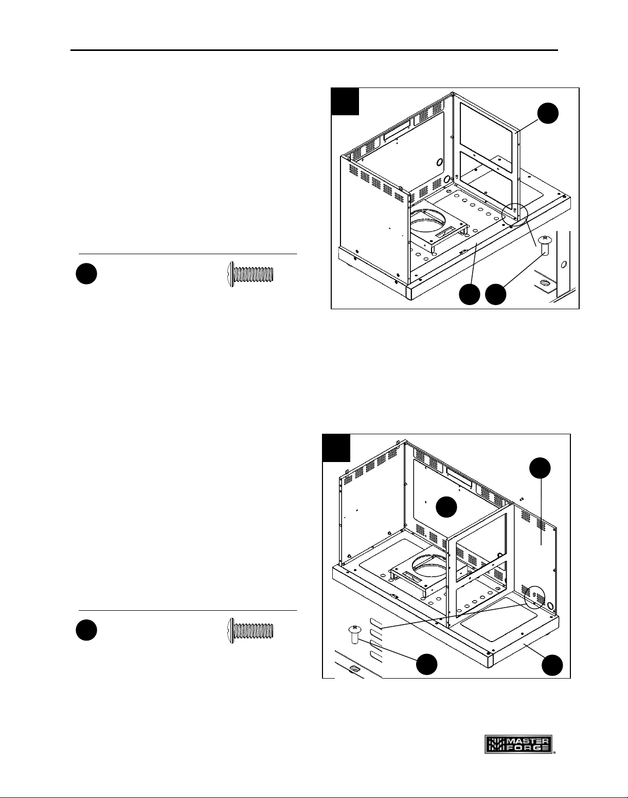
1. Align the casters (Q and T) with the holes
of the main bottom panel (S).
Use the wrench (FF) to tighten. When this
process is completed, turn the bottom panel
over.
The two locking casters (Q) should be at
the back of the grill. (Fig. 1)
2. Attach the tank support (O) to the main
bottom panel (S) with six screws (BB).
(Fig. 2)
Hardware Used
1/4-20 x 5/8 in.
Screw
X 6
BB
2
BB
O
S
S
1
T
Q

ASSEMBLY INSTRUCTIONS
10
Lowes.com/masterfor
g
e
3. Align the holes in the left rear panel (I)
with the holes in the main bottom panel (S) and
insert the screws (BB) into the aligned holes.
(Fig. 3)
Note: Do not tighten the screws completely.
Leave at least one full turn on each.
After all the screws have been installed,
go back and tighten them fully.
4. For left panel (AB), there are six
screws (BB) to connect to the left rear panel (I)
and main bottom panel (S), three in the rear
and three inside the cabinet. Insert the screws
into the aligned holes and tighten them. The
three screws inside the cabinet should be
engaged first. (Fig. 4)
Hardware Used
1/4-20 x 5/8 in.
Screw
X 4
BB
Hardware Used
1/4-20 x 5/8 in.
Screw
X 6
BB
3
I
S
BB
4
AB
I
BB
S
ASSEMBLY INSTRUCTIONS
11
Lowes.com/masterfor
g
e
5. Align the holes in the Center Panel (K)
with the holes in the main bottom panel (S)
and insert the screws (BB) into the
aligned holes and tighten them. (Fig. 5)
Note: Do not tighten the screws completely.
Leave at least one full turn on each.
6. For right rear panel (J), there are four
screws (BB) to connect to the left rear panel (I)
and main bottom panel (S), three in the rear
and one inside the cabinet. Insert the screws
into the aligned holes. After all the screws
have been installed, tighten the three screws
installed during step 5 and the one inside the
cabinet first, and then tighten the three in the
rear. (Fig. 6)
Hardware Used
1/4-20 x 5/8 in.
Screw
X 3
BB
Hardware Used
1/4-20 x 5/8 in.
Screw
X 4
BB
5
K
S BB
6
J
BB
I
S

ASSEMBLY INSTRUCTIONS
12
Lowes.com/masterfor
g
e
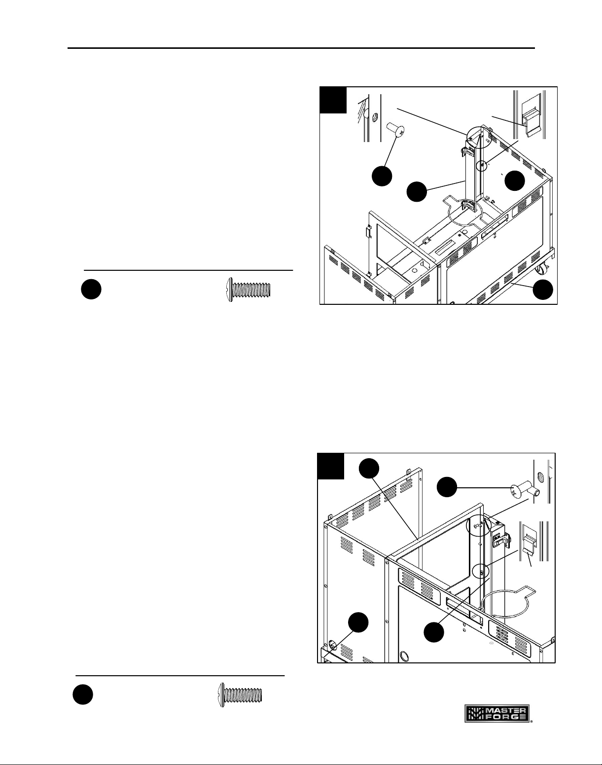
7. Slide the tank ring bracket (M) to the end
of the patented safety tank ring (AC) as shown.
Then align the holes in the ring bracket with
left rear panel (I), insert screws (BB)
into the holes from outside of grill, and then
tighten completely.
(Fig. 7)
8. For the door magnet (L), there are four
screws (CC) to connect to the center panel (K).
Insert the screws into the aligned holes and
tighten them. (Fig. 8)
Hardware Used
1/4-20 x 5/8 in.
Screw
X 2
BB
7
BB
M
AC
I
8
CC
L
K
CC
Hardware Used
5/32-32 x 3/8 in.
Screw
X 4

ASSEMBLY INSTRUCTIONS
13
Lowes.com/masterfor
g
e
9. For right panel (P), there are six screws
(BB) to connect to the right rear panel (J) and
the main bottom panel (S), three in the rear and
three inside the cabinet. Insert the screws into
the aligned holes and tighten them. The three
screws inside the cabinet should be engaged
first. (Fig. 9)
10. For shelf board (N), there are four screws
(BB) to connect to the center panel (K) and
the right panel (P).
Insert the screws into the aligned holes and
tighten them. (Fig. 10)
Hardware Used
1/4-20 x 5/8 in.
Screw
X 6
BB
Hardware Used
1/4-20 x 5/8 in.
Screw
X 4
BB
10
K
P
BB
N
9
J
P
BB
S
ASSEMBLY INSTRUCTIONS
14
Lowes.com/masterfor
g
e
11. For left skirt (Z), there are four screws (BB)
to connect to the left panel (AB) and main bottom
panel (S), two in the left panel and two inside
the cabinet. Make sure the tab A is locked in place.
Insert the screws into the aligned holes and tighten
them. The two screws inside the cabinet should be
engaged first. (Fig. 11)
12. Insert the “Tab A” in right skirt (V) into
the square hole in the Center Panel (K) and
push down. Make sure the tab is locked in
place. For this skirt, there are four screws
(BB) to connect to the center panel (K) and
main bottom panel (S), two in the middle
panel and two inside the cabinet. Insert the
screws into the aligned holes and tighten them.
The two screws inside the cabinet should be
engaged first. (Fig. 12)
Hardware Used
1/4-20 x 5/8 in.
Screw
X 4
BB
Tab A
12
BB
V
K
S
11
BB
Z
AB
S
Tab A
Hardware Used
1/4-20 x 5/8 in.
Screw
X 4
BB

ASSEMBLY INSTRUCTIONS
15
Lowes.com/masterfor
g
e
13. Align the holes in the hinges of the two
doors (X and Y) with the two skirts (V and Z),
insert flat head screws (DD) into the holes,
and then tighten. (Fig. 13)
14. Align the holes in the main beam (W)
with side panels (P and AB) and two skirts
(V and Z), insert screws (BB) into the holes,
and then tighten.
There are four screws to connect the side
panels and two screws to connect the skirts.
(Fig. 14)
Hardware Used
1/4-20 x 5/8 in.
Screw
X 6
BB
Hardware Used
Flat Head 5/32-32
x 1/2 in. Screw
X 8
DD
Y
X
DD
13
V
Z
P
W
14
V
Z
BB
AB

ASSEMBLY INSTRUCTIONS
16
Lowes.com/masterfor
g
e
15. For right door (U), insert bottom hinge
pin into hole in the main bottom panel (S).
Push down on top hinge pin to insert into
hole on the main beam (W). Loosen the
screws holding the magnets to center
panel (K). Adjust magnets to contact the
right door, then tighten the screws again.
(Fig. 15)
16. Align the holes in the drip tray support
(AE) with the holes in the main beam (W)
and in the left rear panel (I). Insert screws (BB)
into the holes and tighten them.
Note the orientation of the drip tray support
as shown. (Fig. 16)
Hardware Used
1/4-20 x 5/8 in.
Screw
X 4
BB
16
BB
AE
W
I
U
W
15
K
S
ASSEMBLY INSTRUCTIONS
17
Lowes.com/masterfor
g
e
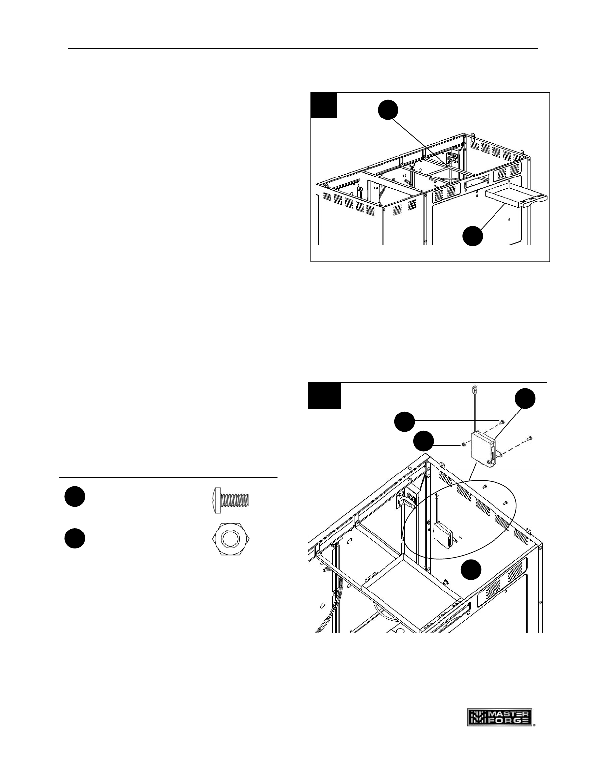
17. Slide the main burner drip tray (AF)
between the drip tray support (AE) from
the back of grill. (Fig. 17)
18. Attach the battery box (AG) to the left
panel (AB) with screws (CC) and nuts (AA).
(Fig. 18)
17
AF
AE
CC
AA
AG
AB
18
Nut
CC
5/32-32 x 3/8 in.
Screw
X 2
Hardware Used
AA
X 2

ASSEMBLY INSTRUCTIONS
18
Lowes.com/masterfor
g
e
19. Take the pressure regulator out from under
the burner box (A). Then lift the burner box (A)
onto the cabinet, making sure that the gas
pressure regulator is in the cabinet, then position
burner box on the cabinet by aligning the four
tabs on top of the cabinet with the holes in the
burner box. Fasten the burner box to the
cabinet with 4 screws (BB). (Fig. 19)
20. Route the light wire from the burner box (A)
through the bottom of the burner box into the
cabinet. Then pull the wire through the
opening in the left rear panel (I).
(Fig. 20)
Hardware Used
1/4-20 x 5/8 in.
Screw
X 4
BB
I
light wire
20
BB
19
A
Tab
Pressure
regulator

ASSEMBLY INSTRUCTIONS
19
Lowes.com/masterfor
g
e
21. Connect the connector which is on the end
of the light wire from step 20 to the transformer (R).
Push the connector to mate firmly with the
transformer. Then, screw and tighten the cap on
the connector. (Fig. 21)
22. On the NG model, pass the natural
gas hose through the hole in the left rear
panel (I) to your gas supply system.
(Fig. 22)
23. Move the covers away the bases of the
grill handle (G), align the holes in the
bases with the holes of the burner box (A).
Insert screws (EE) into the aligned holes
and then tighten them. After tightening the
screws, move the covers onto the bases.
(Fig. 23)
22
NG hose
I
EE
23
G
A
I
R
21
connector
Hardware Used
3/16-24 x1/2 in.
Screw
X 4
EE

ASSEMBLY INSTRUCTIONS
20
Lowes.com/masterfor
g
e
24. Loosen the eight screws in the side
panel of burner box and the bottom panel
three turns. This will allow for quick assembly
of the buffet table. (Fig. 24)
25. Align the holes of the hinges in the
buffet table (AD) with the holes in the burner
box and the main bottom panel.
Tighten the eight screws loosened during
step 24. (Fig. 25)
24
25
AD

ASSEMBLY INSTRUCTIONS
21
Lowes.com/masterfor
g
e
26. Slide the sear burner drip tray (F) from
the back of burner box (A) to the sear burner
bracket. (Fig. 26)
27. Put a battery (H) into the electronic
ignition with correct pole direction.
(Please refer to the battery mark on the
side of the cap). Push and turn the knobs to
check if there are sparks produced between
the ignition pin and the main burner.
If not, please refer to the troubleshooting
section to solve the problem.
(Fig. 27)
26
F
A
Sear burner bracket
27
H

ASSEMBLY INSTRUCTIONS
22
Lowes.com/masterfor
g
e
28. Connect the joint of the battery box (AG)
with the joint of the LED light wire.
(Fig. 28)
Note: 4 batteries included in the package
must be put into the battery box.
29. Position the sear burner grid (E),
5 heat tents (B), 3 main grids (C),
and 1 warming rack (D) into place.
(Fig. 29)
29
D
C
B
E
28
Joint
AG
AB

ASSEMBLY INSTRUCTIONS
23
Lowes.com/masterfor
g
e
IMPORTANT
CHECK SPARKS
After you complete your grill assembly, test your ignition system with the GAS OFF.
Check for continuous sparks when pushing in the knob ignition system.
For the side burner, sparks can be seen directly. For main burners, the ignition system
is positioned next to each burner inside the burner box. A reflection of sparks or sparks
can be seen at the front of the inside of the burner box. Or you can place a mirror on the
left of each main burner and see the sparks and hear the click of the igniters. Be sure the
GAS IS OFF when you push in the control knobs. This will help assure a trouble-free
ignition when you turn on the gas.
ASSEMBLED GRILL DIMENSION (INCHES):
48.5 (HEIGHT) x 81.9 (WIDTH) x 24.8 (DEPTH) (TABLE FOLDED OUT)
48.5 (HEIGHT) x 52.5 (WIDTH) x 24.8 (DEPTH) (TABLE FOLDED DOWN)
WARMING RACK AREA (SQUARE INCHES): 211
THE UL LABEL IS ON THE BACK OF THE DOOR, SHOWN AS PICTURED BELOW
.

COOKING WITH GAS
24
Lowes.com/masterfor
g
e
For Portable LP-Gas Connection
The cabinet has an opening in the bottom panel that allows a 20 lb. gas tank bottom flange to
drop into place (tank sold separately). This will help to lock the tank in place. Before installing
your gas tank, lift up the patented safety tank ring (as shown in Fig. 29a). After positioning the
tank in the opening, lower the patented safety tank ring to lock the tank. Use only 20 lb. gas
tank (see LP Gas Safety Requirements for Additional Information). As shown in Fig. 29b, it
is unsafe to operate the grill if the gas tank is not vertical.
Fig. 29a Fig. 29b
Fig. 30
The propane tank valve connection supplied with this grill incorporates the four important safe
guards: Hand Assembly, Hand Disassembly, Excess Flow Control and Temperature-Activated
Shut-Off.
WARNING: The Type I connective coupling (see Fig. 30) supplied with your grill must
not be replaced with a different type of grill/tank connection system. Removal will
result in loss of warranty, gas leakage, fire and severe bodily harm.
HAND WHEEL
TYPE I VALVE
EXTERNAL
THREAD
THERMALLY
SENSITIVE NUT
PROPANE
REGULATOR
LP Tank

COOKING WITH GAS
25
Lowes.com/masterfor
g
e
a. Hand Assembly:
1. Make certain the tank valve and all the appliance valves are in the “OFF” positions.
2. When connecting the regulator/burner valve assembly to the tank valve, turn the large
plastic nut clockwise until it stops.
3. Gas will not flow unless the plastic nut is completely connected.
4. HAND TIGHTEN ONLY.
b. Hand Disassembly:
1. Make certain the tank valve and all the appliance valves are in the “OFF” positions.
2. Turn the large plastic nut counter-clockwise until it is disassembled.
3. HAND LOOSEN ONLY.
c. Excess Flow Control and Low Heat
The propane regulator assembly incorporates an excess flow device designed to supply the
grill with sufficient gas flow under normal conditions yet control excess gas flow.
Rapid changes in pressure can trigger the excess flow device providing a low flame and low
temperature. If the tank valve is turned open to allow gas flow while a burner valve is open,
the surge of pressure will cause the device to activate. The device will remain closed until the
pressure is equalized. This should occur within 5 seconds.
To ensure this does not cause difficulty in lighting the grill, follow these instructions:
1. Make sure all burner valves are “OFF”.
2. Open the tank valve and wait 5 seconds.
3. Light the burners one at a time following the lighting instructions.
d. Temperature-Activated Shut-Off
The large plastic nut on the regulator assembly is designed in coordination with a check valve
in the tank valve to shut off the flow of gas when exposed to temperatures between
240-300° F.
In the event of a fire or hose break, one of the safeguards will function to control or stop the
flow of gas from the propane tank. Never attempt to use damaged equipment.
Important: Before the use of a fresh tank of gas, please check leakage around the
connections according to section ‘Checking Gas Leaks’ , and make sure there is no
leakage or vapor accumulation in the cabinet. Make sure all openings around side
walls are not blocked.
Important: Place dust cap on cylinder valve outlet whenever the cylinder is not in use.
Only install the type of dust cap on the cylinder valve outlet that is provided with the
cylinder valve. Other types of caps or plugs may result in leakage of propane.

COOKING WITH GAS
26
Lowes.com/masterfor
g
e
For Natural Gas Connection
Preparing:
1. Turn off gas supply, and then remove cap on gas supply side.
2. Recommended: Install a shut-off valve on gas supply side before installing the socket.
3. Socket should be installed by an authorized technician in accordance with the national
fuel gas code (NFPA 54/ANSI223.1).
4. Before inserting plug, turn on gas supply and leak test all connections including the stem
of the shut-off valve and the opening of the socket. For best results, use an
ammonia-free soap and water solution.
Operating Instructions:
1. To connect, push back socket sleeve (Fig. 31).
2. Insert plug and release sleeve (Fig. 32).
3. Push plug until sleeve snaps forward (Fig. 33).
(Gas will flow automatically. Failure to connect
plug properly to socket will inhibit gas flow to
the appliance.)
Fig. 33
4. Test connection with ammonia-free soap and water solution.
To disconnect
1. Pull sleeve back. Pull plug out of socket. (Gas is automatically shut off.)
2. Close shut-off valve and replace dust caps on socket and plug.
Gas Requirements
The 3218LTN grill is set and tested at the factory for the type of gas supply to be used.
Identify the type of gas, either natural gas or LP gas, and make sure the marking on the rating
plate matches the gas supply. The rating plate is located on the inside panel of the left door.
Sleeve
Socket
Plug
Socket
Sleeve
Fig. 31
Sleeve
Socket
Fig. 32

COOKING WITH GAS
27
Lowes.com/masterfor
g
e
LP Gas
If your grill is for LP Gas, the regulator supplied is set for an 11-in. water column (WC) and is
for use with LP gas only. The factory-supplied regulator and hose must be used with a 20-lb.
LP gas tank.
Natural Gas
Your grill 3218LTN is natural gas convertible. NG kit sold separately (Item #0050772). Please
follow the manual to convert your grill to natural gas.
If your grill is for Natural Gas, it is set for a 7-in. water column (WC) and is for use with Natural
Gas only. Gas pressure is affected by gas line size and the length of gas line run from the
house gas line. Follow the recommendations in the chart below.
From House to Grill
Distance Tubing Size
Up to 25 ft. 3/8 in. DIA
26-50 ft. 1/2 in. DIA
51-100 ft.
2/3 in. of run 3/4 in.
1/3 in. of run 1/2 in.
Over 101 ft. 3/4 in. DIA
LP GAS System
Contact your gas supplier for a special regulator for bulk gas that fuels other
appliances.
Gas Consumption
Total gas consumption of this grill with the burner(s) on “HIGH”: Table 1 below.
Table 1
Burner Type BTU/HR
Main Burners 12000 x 5
Sear Burner 12000 x 1
Rotisserie Burner 13000 x 1
LP Gas Safety Requirement
For LP gas grills, the LP gas supply tank to be used must be:
(a) Constructed and marked in accordance with the Specifications for LP Gas Tanks of the
U.S. Department of Transportation (DOT) or the National Standard of Canada,
CAN/CSA-B339 Cylinders, Spheres and Tubes for Transportation of Dangerous Goods;
and Commission, as applicable.
(b) Provided with a listed Overfill Prevention Device (OPD).

COOKING WITH GAS
28
Lowes.com/masterfor
g
e
(c) Provided with a tank connection device compatible with the connection for outdoor
cooking appliances.
The tank should be 12 inches in diameter and 18-1/2 inches tall and be equipped with a
Type-1 fitting.
The tank supply system must be arranged for vapor withdrawal.
The tank used must include a collar to protect the cylinder valve.
Do not operate the gas grill indoors or in any enclosed area. If the gas grill is not in use, the
gas must be turned off at the supply tank. If the grill is to be stored indoors, disconnect the
gas supply tank and store the tank in an upright position in a cool, well-ventilated outdoor
location away from your grill or any other heat source.
When checking for gas leaks, do not use an open flame. Use a soapy water solution and
apply it to the pipe joints and fittings with a brush and check for bubbles. Check flexible hoses
for cuts and wear that may affect the safe operation of the grill. Only the factory supplied hose
and regulator must be used. Use only replacement regulator and hose assemblies specified
by manufacturer.
Checking Gas Leaks
Before operating your grill, after refueling, check carefully to be certain that all connections
are tight and there are no gas leaks.
1. Make 2-3 ounces of leak solution by mixing liquid dishwashing soap with water.
2. Make certain all control knobs are in the “OFF” position.
3. Brush small amounts of the leak solution on all the fittings and turn the gas on.
4. If bubbles appear, there is a leak. Proceed to step 5.
5. Turn the gas off and tighten all connections.
6. Go back to step 1 to retest the fittings.
7. If bubbles continue to appear, turn the gas off. Contact customer service.
WARNING: Never use a match or open flame for leak detection. Use of an open flame
could result in a fire, explosion and bodily harm.
IMPORTANT: When connecting or replacing any gas pipe or fittings, all joints must be
sealed with approved leak-proof sealing compound or plumber’s tape.
Handling the Liquid Propane Tank Safely
Remember to handle your portable liquid propane tank carefully when you take it to your
dealer for a refill. Avoid dropping it or bumping it against sharp objects. Liquid propane tanks
are sturdily constructed, but a series of hard jolts could damage the container.

COOKING WITH GAS
29
Lowes.com/masterfor
g
e
When transporting the tank to your local propane gas dealer, make sure the valve is closed
tightly and the protective cover is in place. Position the tank securely in an upright position so
it will not roll around your vehicle.
If you plan to make stops for shopping or errands, have your liquid propane tank filled at the
last stop before going home. Again, make certain the refilled tank is secure and in an upright
position. When you return home, remove the refilled tank from your vehicle. Never leave a
portable liquid propane tank inside a vehicle that may become overheated by the sun.
Your local liquid propane gas dealer will gladly offer you additional safety tips.
Storing the Liquid Propane Tank Safely
Whether you are between cross-country treks in your recreational vehicle or looking for a
place to keep the liquid propane tank to provide fuel for your outdoor grill, keep in mind some
basic safety rules about storing portable liquid propane tanks:
Do not store the tanks (whether full or empty) inside your home, the living area of an R.V., a
garage, basement or workshop. It is unlikely that liquid propane will leak from the tanks. If it
should leak, the fuel could be exposed to sparks from automobiles, power tools or other
appliances. When storing or transporting your LP tank, it must remain in an upright position.
Never lay your LP tank down on its side whether it is full or empty. Never store a spare tank
under or near your grill.
CAUTION: Never transport or move your grill or grill tank without first closing the
manual valve on your liquid propane gas tank.
The best place to store a liquid propane tank is in a shady or protected spot outdoors, behind
your home or garage, or on a screened porch but where it is out of reach of children. Liquid
propane will not evaporate. It is in a strong, closed container. It will not lose any of its
clean-burning heat content, even if left outside year-round.
WARNING: When not connected to your grill, the LP gas tank must be stored in an
upright position in a cool, shady, well-ventilated, outdoor location away from your grill
or any other heat source. Failure to follow this warning could lead to tank valve
damage, fire hazard and personal injury.
Refilling a Propane Tank
It is extremely important that your LP tank be filled properly when you take it to be refilled. Be
sure to use a reputable LP dealer and observe how the tank is filled and at what capacity. An
overfilled LP tank can be dangerous.

COOKING WITH GAS
30
Lowes.com/masterfor
g
e
The proper way to fill a tank is by weight. The empty tank should be placed on a scale. The
scale weights should be readjusted to a weight that would allow up to 80% of the total weight.
The filling operation must end once the tank is filled to 80% of its total capacity. If the tank is
not completely empty, the scale readjustment must be changed to consider the propane (LP)
already in the tank.
WARNING: An LP (propane) tank is overfilled if it contains more than 80% of its total
capacity of propane (LP).
An incorrectly filled or an overfilled LP (propane) tank can be dangerous. If a tank is overfilled
and the weather causes the warming of the LP tank, (a hot day, tank left in sun or stored
indoors) internal pressure is created due to expansion of the propane which in turn may
cause the LP gas to be released through the pressure relief valve on the tank. The pressure
relief valve is a safety device required on 20 lb. propane tanks by the Department of
Transportation to prevent a catastrophic tank failure due to excessive pressure. LP gas
released from the tank is flammable and can be explosive.
IMPORTANT: When connecting or replacing gas pipe or fittings, all joints must be
sealed with approved leak-proof sealing compound or plumber’s tape. After making
connections, check all joints for leaks using a soapy water solution and a brush.
WARNING: Never use an open flame to test for gas leaks. Use of an open flame could
result in a fire, explosion and bodily harm.
Locating the Grill
This gas appliance is designed and certified for outdoor use only. Do not operate the grill
inside a building, garage, recreation vehicle, screened porch or any enclosed area. Keep the
grill away from windy areas, but keep the grill in a well-ventilated area. Do not obstruct the
flow of combustion and ventilation air around the grill.
Warning: Do not place the grill under overhead, unprotected combustible surfaces.
Clearance to Combustible Construction
A minimum clearance of 36 in. from the sides of the grill, and a minimum clearance of 36 in.
from the back of the grill to adjacent vertical combustible constructions must be maintained.
However, the manufacturer strongly suggests a 6 ft. clearance of the grill to combustible
constructions.
Clearance to Noncombustible Construction
A minimum clearance of 36 in. from the back of the grill above the cooking surface to
noncombustible constructions is required to allow the grill hood to open completely. A
minimum of 36 in. clearance to the sides of the grill above the cooking surface to
noncombustible constructions is recommended. The grill can be installed directly next to
noncombustible construction below the cooking surface.
 Loading...