

Page 1

OPERATING MANUAL:
®
®
MASTERFLEX®B/T®Pump 77111-60
B/T®RAPID-LOAD
®
PERISTALTIC PUMPS
AND DRIVES
System Model Nos.
77111-10
77111-12
77111-15
77111-17
77111-30
77111-37
77111-40
77111-47
77111-50
77111-55
77111-60
77111-67
77111-80
A12995152B
Edition 04
(US & Canada only) Toll Free 1800MASTERFLEX • 18006373739
(Outside US & Canada) 18475497600 • 18473817050
www.masterflex.com • techinfo@masterflex.com
Page 2

© 2019 Cole-Parmer Instrument Company. All rights reserved.
Chem-Durance, B/T, Rapid-Load, Masterflex – Reg TM of Cole-Parmer Instrument Company
C-FLEX, NORPRENE, PHARMAPURE, PHARMED, TYGON – Reg TM Saint-Gobain Performance Plastics Corp.
Trademarks bearing the ®symbol in this publication are registered in the U.S. and in other countries.
PUMP FOR LIQUIDS
ORIGINAL INSTRUCTIONS
Masterflexii B/T®RAPID-LOAD®Peristaltic Pumps and Drive Operating Manual
Page 3
Preface
Safety Precautions
SAFETY
PRECAUTIONS
DANGER: High voltages exist and are accessible. Do not remove cover of
Drive or Controller. Use extreme caution when servicing internal components.
CAUTIONS: Risk of electric shock – this pump is supplied with a grounding
conductor and grounding-type attachment plug. To reduce risk of electric
shock, be certain that it is connected only to a properly grounded, groundingtype receptacle.
Electrical connections and grounding (earthing) must conform to local wiring
codes.
WARNINGS: Tubing breakage may result in fluid being sprayed from pump.
Use appropriate measures to protect operator and equipment.
To reduce the risk of injury, use hose clamps on all tubing connections. All
tubing connections, must be made outside of the pump.
To reduce risk of injury, power must be removed from pump before removing
or installing tubing. Fingers or loose clothing could get caught in drive
mechanism. Do not operate this pump without cover or interlock door properly
closed and latched. Rotating parts can cause serious injury.
To reduce risk of injury, do not pump materials hotter than 150 degrees
Fahrenheit, (65.5°C).
Explanation of
Symbols
WARNING:
Product Use
Limitation
Before permanent installation, test the equipment with the chemicals and under
the specific conditions of your application.
Verify tubing material chemical compatibility prior to use. It is the sole
responsibility of the user to determine suitability of the product for the
application
CAUTION: Risk of Danger. Consult Operator’s manual for nature of hazard and
corrective actions.
CAUTION: Risk of crushing. Keep fingers away from rotor while pump is in
operation. Stop pump before loading or unloading tubing.
CAUTION: Hot Surface. Do not touch.
CAUTION: Risk of electric shock. Consult Operator’s manual for nature of
hazard and corrective actions.
This product is not designed for, nor intended for use in, patient-connected
applications, including, but not limited to, medical and dental use, and,
accordingly, has not been submitted for FDA approval. If drive is used in a
manner not specified in this manual the protection provided by the equipment
may be impaired.
Masterflex
®
Use only MASTERFLEX
MASTERFLEX pumps to ensure optimum performance. Use of other tubing may
void applicable warranties.
PERFECTPOSITION®B/T®precision tubing with
®
RAPID-LOAD®Peristaltic Pumps and Drive Operating Manual iii
B/T
Page 4

Page 5

Section 1
Table of Contents
Page
INTRODUCTION . . . . . . . . . . . . . . . . . . . . . . . . . . . . . . . . . . . . . . . . . . . . . . . . . . . .1-1
APPLICATION DATA . . . . . . . . . . . . . . . . . . . . . . . . . . . . . . . . . . . . . . . . . . . . . . . . . .1-2
GENERAL DESCRIPTION . . . . . . . . . . . . . . . . . . . . . . . . . . . . . . . . . . . . . . . . . . . . . . .1-3
Section 2
Section 3
Section 4
INSTALLATION AND SETUP . . . . . . . . . . . . . . . . . . . . . . . . . . . . . . . . . . . . . . . . .2-1
PUMP MOUNTING DIMENSIONS . . . . . . . . . . . . . . . . . . . . . . . . . . . . . . . . . . . . . . .2-1
CONTROL BOX MOUNTING DIMENSIONS (Digital Models Only) . . . . . . . . . . . . . .2-1
CONTROL BOX MOUNTING DIMENSIONS (Analog Models Only) . . . . . . . . . . . . . .2-2
MODEL 77111-80 . . . . . . . . . . . . . . . . . . . . . . . . . . . . . . . . . . . . . . . . . . . . . . . . . . . .2-3
MODEL 77111-50 . . . . . . . . . . . . . . . . . . . . . . . . . . . . . . . . . . . . . . . . . . . . . . . . . . . .2-4
MODEL 77111-55 . . . . . . . . . . . . . . . . . . . . . . . . . . . . . . . . . . . . . . . . . . . . . . . . . . . .2-5
TUBING TYPES . . . . . . . . . . . . . . . . . . . . . . . . . . . . . . . . . . . . . . . . . . . . . . . . . . . . . .2-6
INSTALLING THE PUMP TUBING . . . . . . . . . . . . . . . . . . . . . . . . . . . . . . . . . . . . . . . .2-7
OPERATION . . . . . . . . . . . . . . . . . . . . . . . . . . . . . . . . . . . . . . . . . . . . . . . . . . . . . . .3-1
CONTROL DISPLAY FUNCTION MODELS 77111-10, 77111-15,
77111-40 AND 77111-47 . . . . . . . . . . . . . . . . . . . . . . . . . . . . . . . . . . . . . . . . . . . . . .3-1
MODELS 77111-12, AND 77111-17 CONTROLLER SETUP . . . . . . . . . . . . . . . . . . . .3-2
MODELS 77111-60 AND 77111-67 . . . . . . . . . . . . . . . . . . . . . . . . . . . . . . . . . . . . . .3-8
MODEL 77111-80 . . . . . . . . . . . . . . . . . . . . . . . . . . . . . . . . . . . . . . . . . . . . . . . . . . . .3-9
MODELS 77111-30 AND 77111-37 . . . . . . . . . . . . . . . . . . . . . . . . . . . . . . . . . . . . .3-10
MAINTENANCE AND TROUBLESHOOTING . . . . . . . . . . . . . . . . . . . . . . . . . . . .4-1
REPLACING MOTOR BRUSHES MODELS 77111-12, 77111-17, 77111-60,
77111-67, 77111-40 AND 77111-47 . . . . . . . . . . . . . . . . . . . . . . . . . . . . . . . . . . . . . .4-1
REPLACING ROLLERS . . . . . . . . . . . . . . . . . . . . . . . . . . . . . . . . . . . . . . . . . . . . . . . . .4-2
MOTOR REPLACEMENT . . . . . . . . . . . . . . . . . . . . . . . . . . . . . . . . . . . . . . . . . . . . . . .4-3
REPLACEMENT PARTS . . . . . . . . . . . . . . . . . . . . . . . . . . . . . . . . . . . . . . . . . . . . . . . .4-4
ACCESSORIES . . . . . . . . . . . . . . . . . . . . . . . . . . . . . . . . . . . . . . . . . . . . . . . . . . . . . . .4-4
CLEANING . . . . . . . . . . . . . . . . . . . . . . . . . . . . . . . . . . . . . . . . . . . . . . . . . . . . . . . . . .4-4
TROUBLESHOOTING MODELS 77111-40 AND 77111-47 . . . . . . . . . . . . . . . . . . . . .4-5
ERROR CODES . . . . . . . . . . . . . . . . . . . . . . . . . . . . . . . . . . . . . . . . . . . . . . . . . . . . . . .4-5
Section 5
Section 6
SPECIFICATIONS AND AGENCY APPROVALS . . . . . . . . . . . . . . . . . . . . . . . . . .5-1
MODELS 77111-10, 77111-12, 77111-15, 77111-17,
77111-40 AND 77111-47 . . . . . . . . . . . . . . . . . . . . . . . . . . . . . . . . . . . . . . . . . . . . . .5-1
MODELS 77111-60 AND 77111-67 . . . . . . . . . . . . . . . . . . . . . . . . . . . . . . . . . . . . . .5-3
MODEL 77111-80 . . . . . . . . . . . . . . . . . . . . . . . . . . . . . . . . . . . . . . . . . . . . . . . . . . . .5-4
MODELS 77111-30 AND 77111-37 . . . . . . . . . . . . . . . . . . . . . . . . . . . . . . . . . . . . . .5-5
MODELS 77111-50 AND 77111-55 . . . . . . . . . . . . . . . . . . . . . . . . . . . . . . . . . . . . . .5-6
WARRANTY, PRODUCT RETURN, TECHNICAL ASSISTANCE . . . . . . . . . . . . .6-1
WARRANTY . . . . . . . . . . . . . . . . . . . . . . . . . . . . . . . . . . . . . . . . . . . . . . . . . . . . . . . .6-1
PRODUCT RETURN . . . . . . . . . . . . . . . . . . . . . . . . . . . . . . . . . . . . . . . . . . . . . . . . . . .6-2
TECHNICAL ASSISTANCE . . . . . . . . . . . . . . . . . . . . . . . . . . . . . . . . . . . . . . . . . . . . . .6-2
B/T®RAPID-LOAD®Peristaltic Pumps and Drive Operating Manual vMasterflex
Page 6

Page 7

Figures
Figures
Page
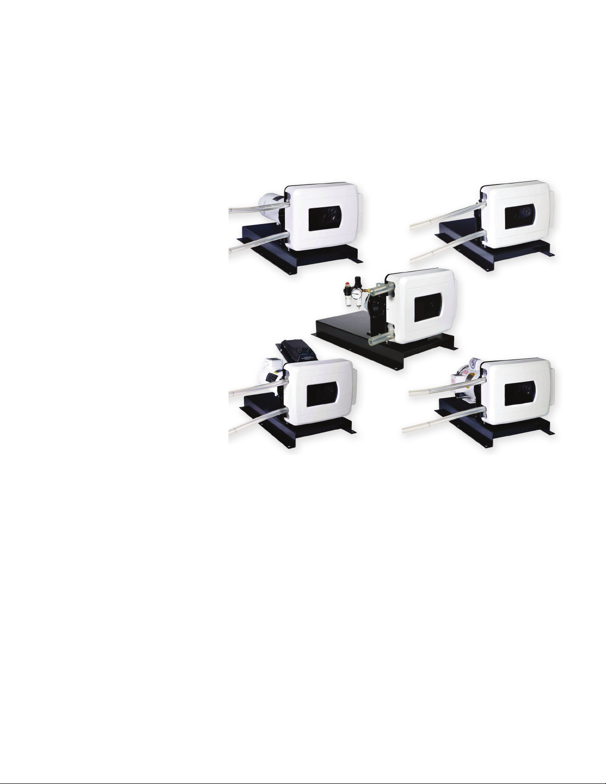
RAPID-LOAD Pump and Drive Family . . . . . . . . . . . . . . . . . . . . . . . . . . . . . . .1-3
RAPID-LOAD Pump and Drive . . . . . . . . . . . . . . . . . . . . . . . . . . . . . . . . . . . . .1-4
Pump Mounting Dimensions . . . . . . . . . . . . . . . . . . . . . . . . . . . . . . . . . . . . . .2-1
Control Box Mounting Dimensions 77111-10, 77111-15,
77111-40 and 77111-47 . . . . . . . . . . . . . . . . . . . . . . . . . . . . . . . . . . . . . . . . .2-1
Control Box Mounting Dimensions 77111-60 (115V) . . . . . . . . . . . . . . . . . . .2-2
Control Box Mounting Dimensions 77111-67 (230V) . . . . . . . . . . . . . . . . . . .2-2
Air-Powered Rapid-Load Pump and Drive . . . . . . . . . . . . . . . . . . . . . . . . . . . .2-3
Motor Mounting NEMA TYPE 56C Motor Fame . . . . . . . . . . . . . . . . . . . . . . .2-4
Motor Mounting IEC-72 71-14F130 Motor Frame . . . . . . . . . . . . . . . . . . . . .2-5
Tubing Retaining Pockets . . . . . . . . . . . . . . . . . . . . . . . . . . . . . . . . . . . . . . . .2-7
PerfectPosition Marks . . . . . . . . . . . . . . . . . . . . . . . . . . . . . . . . . . . . . . . . . . .2-8
Tubing Retaining Pockets . . . . . . . . . . . . . . . . . . . . . . . . . . . . . . . . . . . . . . . .2-8
Control Panel . . . . . . . . . . . . . . . . . . . . . . . . . . . . . . . . . . . . . . . . . . . . . . . . . .3-1
Connectors and Switch on Controller Side Panel . . . . . . . . . . . . . . . . . . . . . .3-2
Remote Control Connector Pin Configuration . . . . . . . . . . . . . . . . . . . . . . . . .3-6
Remote Control Wiring Schematic . . . . . . . . . . . . . . . . . . . . . . . . . . . . . . . . .3-7
Controller . . . . . . . . . . . . . . . . . . . . . . . . . . . . . . . . . . . . . . . . . . . . . . . . . . . . .3-8
Model 77111-80 . . . . . . . . . . . . . . . . . . . . . . . . . . . . . . . . . . . . . . . . . . . . . . .3-9
Model 77111-30 . . . . . . . . . . . . . . . . . . . . . . . . . . . . . . . . . . . . . . . . . . . . . .3-10
Motor Brush . . . . . . . . . . . . . . . . . . . . . . . . . . . . . . . . . . . . . . . . . . . . . . . . . . .4-1
Exploded Roller Sub-Assembly . . . . . . . . . . . . . . . . . . . . . . . . . . . . . . . . . . . .4-2
Motor Mounting . . . . . . . . . . . . . . . . . . . . . . . . . . . . . . . . . . . . . . . . . . . . . . .4-3
B/T®RAPID-LOAD®Peristaltic Pumps and Drive Operating Manual viiMasterflex
Page 8

Page 9

Tables
Tables
Page
Tubing Types . . . . . . . . . . . . . . . . . . . . . . . . . . . . . . . . . . . . . . . . . . . . . . . . . .2-6
B/T®RAPID-LOAD®Peristaltic Pumps and Drive Operating Manual ixMasterflex
Page 10

Page 11

Section 1 Introduction
This manual provides information for installing, operating and servicing
the following models of MASTERFLEX
Pumps and Drives.
MODEL TYPE
77111-10 Controller Only 115VAC for 77111-40
77111-12 Drive Only 115VAC for 77111-40
77111-15 Controller Only 230VAC for 77111-47
77111-17 Drive Only 230VAC for 77111-47
77111-30 Fixed Speed w/TEFC, 115V AC @ 60 Hz
77111-37 Fixed Speed w/TEFC, 230V AC @ 50 Hz
77111-40 Modular Drive , Digital 115V AC system.
77111-47 Modular Drive , Digital 230V AC system.
77111-50 Drive Only NEMA56C mount less motor
77111-55 Drive Only IEC72 mount less motor
77111-60 Modular Drive, Analog 115V AC system
77111-67 Modular Drive, Analog 230V AC system
77111-80 Air-Powered Variable Occlusion Peristaltic Pump and Drive.
B/T®RAPID-LOAD®Peristaltic
®
The unique design of these peristaltic pumps provides a greatly simplified
means for rapid loading and changing of tubing. In addition, the following
features are incorporated:
Pumps up to 11.1 GPM (42.0 LPM).
Uses continuous tubing to ensure a sanitary and non-contaminating
system.
Fluid contacts only the tubing.
Handles wide range of viscosities.
Several different sizes and formulations of tubing can be used.
B/T®RAPID-LOAD®Peristaltic Pumps and Drive Operating Manual 1-1Masterflex
Page 12

Section 1
Introduction
Application Data
The gentle peristaltic action of these pumps is ideal for pumping highly
viscous and shear-sensitive liquids. These pumps are also ideally suited for
use where sterile conditions and purity are required. Toxic and hazardous
fluids can be pumped with the proper selection of MASTERFLEX
PERFECTPOSITION B/T tubing since the fluid contacts only the
tubing and not the pump.
Use only MASTERFLEX®PERFECTPOSITION®B/T®precision tubing
with MASTERFLEX pumps to ensure optimum performance. Use of
other tubing may void applicable warranties.
WARNING: Tubing breakage may result in fluid being sprayed
from pump. Use appropriate measures to
protect operator and equipment.
Verify tubing material chemical compatibility prior to use. It is
the sole responsibility of the user to determine suitability of the
product for the application.
1-2 B/T®RAPID-LOAD®Peristaltic Pumps and Drive Operating Manual Masterflex
Page 13
Section 1
Note:
Introduction
General Description
The RAPID-LOAD®B/T peristaltic pump (see Figure 1) is mounted on a
base and attached to a NEMA 56C frame motor or IEC-72 71-14F130
frame motor through a 5.45:1 gear head and adapter. Depending on the
model, the motor is either supplied or customer furnished and is attached
to the adapter by four bolts. A modular controller is furnished with some
models. The modular controller can be wall mounted.
Figure 1-1. RAPID-LOAD Pump and Drive Family
Due to its unique design, different MASTERFLEX PERFECTPOSITION
B/T tubing sizes can be accommodated by this RAPID-LOAD peristaltic
pump.
For an indirect estimate of flow rate, a reflective element attached to the
rotor has been provided for use with an optical tachometer. Point
tachometer beam through front cover window and target the reflective
element.
To obtain flow rate in mL/min., multiply tachometer rpm reading times
the nominal flow per revolution value provided in TABLE 1
(N
3,785 mL = 1 U.S. liquid gallon).
B/T®RAPID-LOAD®Peristaltic Pumps and Drive Operating Manual 1-3Masterflex
Page 14
Section 1
Introduction
The maximum recommended rotor speed is 321 rpm. The pump rotor can
turn either clockwise or counterclockwise. When turning clockwise (FWD)
the top connection is for suction and the bottom connection is for
discharge. The 321 rpm speed is obtained from the standard 1725 rpm
fractional horsepower motor through the 5.45:1 gear reduction. Faster
speeds will increase flow, but will also considerably shorten average tubing
life. (Manufacturer cannot be responsible for pump performance when
operated at speeds higher than 321 rpm.)
WARNING: To reduce the risk of injury, use hose clamps on all
tubing connections.
Silicone or C-FLEX®tubing, because of their highly elastic natures, can
expand very quickly if back-pressure is present and could create leakage at
the fittings if not securely retained. It is this same elastic nature, however,
that makes them such excellent materials for this peristaltic type pump.
®
NORPRENE
tubing yields longer life, especially under pressure. Refer to
Table 1 for tubing recommendations. Do not attempt to use other
materials in lieu of these, as pump performance could be severely
compromised with possible damage to the pump.
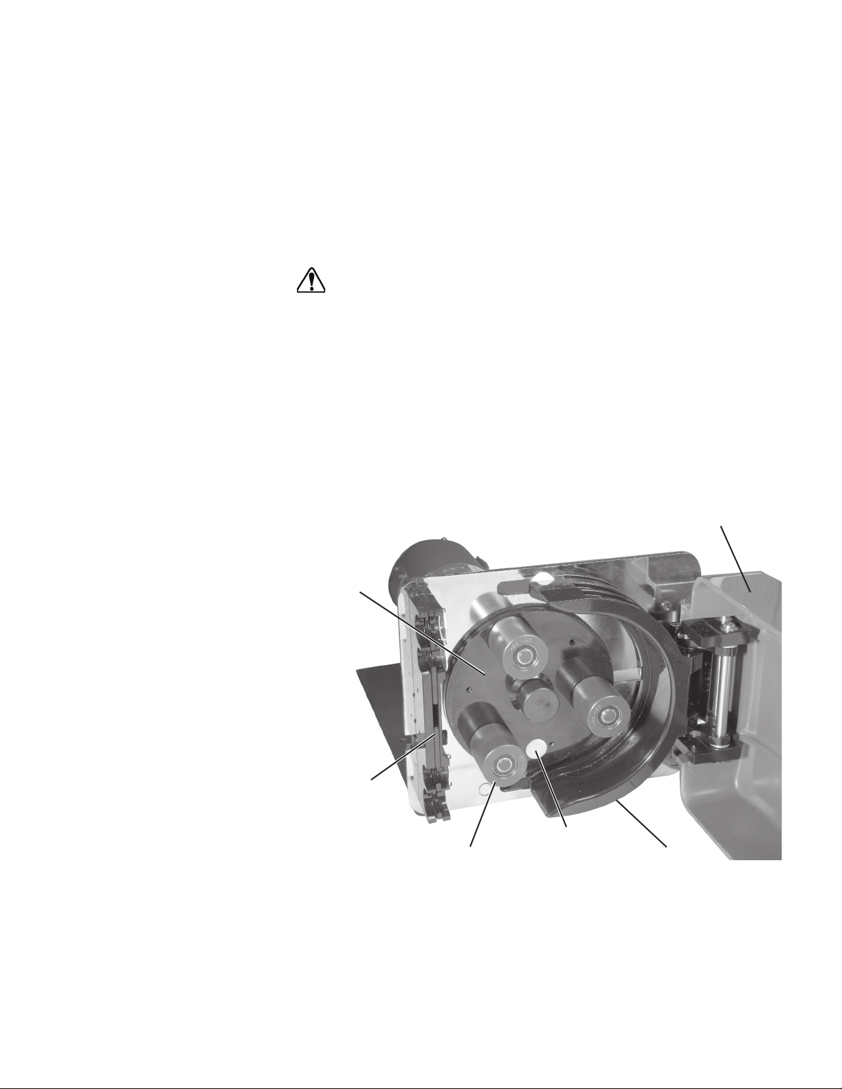
ROTOR
ASSEMBLY
RETAINER
ASSEMBLY
ROLLER
Figure 1-2. RAPID-LOAD Pump and Drive
REFLECTIVE
ELEMENT
DOOR ASSEMBLY
OCCLUSION BED
1-4 B/T®RAPID-LOAD®Peristaltic Pumps and Drive Operating Manual Masterflex
Page 15
PUMP MOUNTING
27.0
(685.80)
15.8
(400.05)
.5
(12.70)
14.8
374.65
25.5
(647.70)
12.8
(323.85)
.3 (6.35)
6
X
.5 (13.49)
.8
(19.05)
DIMENSIONS
(All Models)
Section 2 Installation and Setup
These units should be placed on a flat surface such as a floor, bench or
table and should be near an electrical power source. Be sure to check data
plate for proper voltage rating(s).
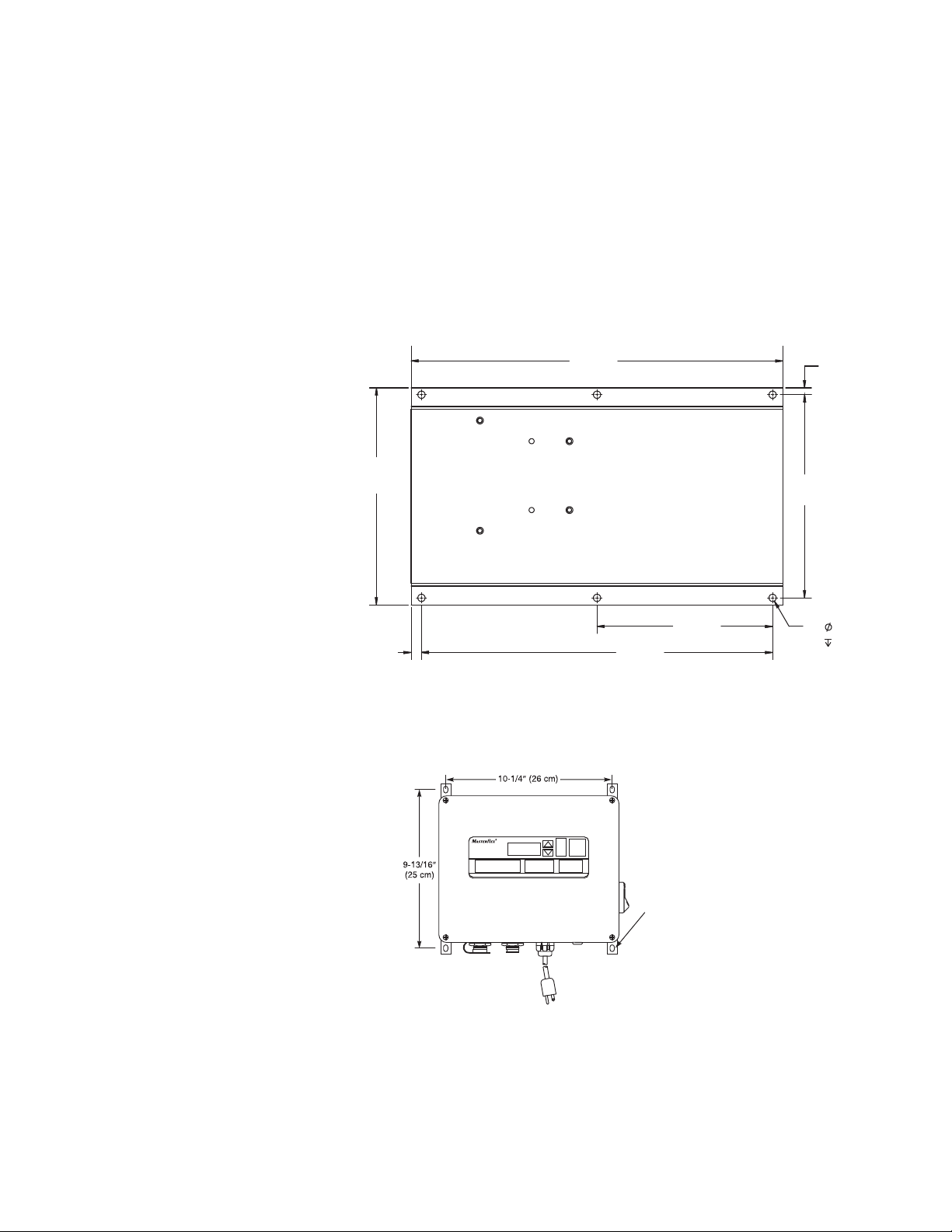
CONTROL BOX
MOUNTING
DIMENSIONS
(Digital Models Only)
Figure 2-1. Pump Mounting Dimensions, applies to all Pump Systems.
CLEARANCE FOR 1/4 IN SCREW
Figure 2-2. Control Box Mounting Dimensions 77111-10, 77111-15, 77111-40
and 77111-47.
B/T®RAPID-LOAD®Peristaltic Pumps and Drive Operating Manual 2-1Masterflex
Page 16

Section 2
7.3
(184)
3.6
(91)
Ø .220
(6)
4 Places
5.5
(140)
5.5
(140)
TYP
5.1
(130)
TYP
3.6
(91)
Ø .165
(4)
4 Places
6.3
(160)
5.1
(130)
9.0
(228)
9.5
(240)
TYP
Installation and Setup
CONTROL BOX
MOUNTING
DIMENSIONS
(Analog Models
77111-60 and
77111-67 Only)
NOTE: The controller and bracket can be removed and located up to
10 feet away.
Figure 2-3. Control Box Mounting Dimensions 77111-60 (115V).
Figure 2-4. Control Box Mounting Dimensions 77111-67 (230V).
2-2 B/T®RAPID-LOAD®Peristaltic Pumps and Drive Operating Manual Masterflex
Page 17

Section 2
Unpack the drive
Install the following components:
Installation and Setup
Model 77111-80
This unit should be placed on a flat surface such as a floor, bench, or table
and should be near a compressed air source.
and save packaging material until proper product
operation has been verified.
pressure gauge, pressure filter/regulator
and lubricator assembly, pipe nipple, elbow, and muffler. See Figure 2-5 for
proper orientation, (all items and fittings included except as noted). Use a
thread seal such as PTFE tape for all connections to reduce the possibility
of air leakage.
Connect compressed air line to the 1/4 NPT connection on the regulator
(fitting not supplied). Turn on compressed air line to start pumping.
(Maximum 100 psig inlet.)
NOTE: Pump will not run unless Door Assembly is closed.
Gear Reducer
Lubricator
Control Knob
Muffler
Door
Assembly
Elbow Pipe Nipple Pressure Gauge
Figure 2-5. Air-Powered Rapid-Load Pump and Drive
Air Motor
Filter/Regulator
Control Knob
(Speed Control)
Base
B/T®RAPID-LOAD®Peristaltic Pumps and Drive Operating Manual 2-3Masterflex
Page 18

Section 2
Trim Interlock Cable to
Length and Strip Leads.
Install in Series with
Power to the Motor.
Gear Reducer
Pump
Head
Flat Washers
and Bolts
Installation and Setup
MODEL 77111-50
Install customer-supplied motors in accordance with the following procedure.
CAUTION: This product is intended for use with a motor that has
a maximum speed of 1800 rpm, @ 1.0 HP (0.75 KW). Do not use a
motor with a higher speed capacity.
WARNING: Electrical connections and grounding (earthing), must
conform to local codes. (See motor wiring diagram for motor
wiring instructions.)
Tools required: 5/16 inch Hex Key.
Model 77111-50 is designed to be installed to a customer-supplied NEMA Type
56C frame motor. To install the unit, refer to Figure 2-6 and follow these steps:
1. Using a 5/16 inch Hex Key, and the supplied hardware, bolt the motor
to the gear reducer by installing the four flat washers on the bolts and
inserting the bolts through the gear head adapter into the motor.
Torque bolts from 17 to 19 foot pounds.
2. Cutoff connector from end of interlock cable and strip outer jacket.
3. Strip individual conductors and wire in series with the power to the
motor turned off. Failure to do so will result in defeating the door
interlock, creating a potential crushing hazard.
CAUTION: Risk of crushing. Keep fingers away from rotor while
pump is in operation. Stop pump before loading or unloading tubing.
Figure 2-6. Motor Mounting NEMA TYPE 56C Motor Fame
2-4 B/T®RAPID-LOAD®Peristaltic Pumps and Drive Operating Manual Masterflex
Page 19

Section 2
Trim Interlock Cable to
Length and Strip Leads.
Install in Series with
Power to the Motor.
Gear Reducer
Pump
Head
Flat Washers
and Bolts
Installation and Setup
MODEL 77111-55
Install customer-supplied motors in accordance with the following procedure.
CAUTION: This product is intended for use with a motor that has
a maximum speed of 1800 rpm, @ 1.0 HP (0.75 KW). Do not use a
motor with a higher speed capacity.
WARNING: Electrical connections and grounding (earthing), must
conform to local codes. (See motor wiring diagram for motor
wiring instructions.)
Tools required: 13 mm Wrench.
Model 77111-55 is designed to be installed to a customer-supplied
IEC-72-71-14F130 frame motor with foot mountings. To install the
unit, refer to Figure 2-7 and follow these steps:
1. Using a 13 mm wrench, and the supplied hardware, bolt the motor to
the gear reducer by installing the four flat washers on the bolts and
inserting the bolts through the gear head adapter into the motor. Torque
bolts from 1.73 to 2.00 kilogram-meters (12.5 to 14.5 foot pounds.)
2. Cutoff connector from end of interlock cable and strip outer jacket.
3. Strip individual conductors and wire in series with the power to the
motor turned off. Failure to do so will result in defeating the door
interlock, creating a potential crushing hazard.
CAUTION: Risk of crushing. Keep fingers away from rotor while pump is
in operation. Stop pump before loading or unloading tubing.
Figure 2-7. Motor Mounting IEC-72 71-14F130 Motor Frame
B/T®RAPID-LOAD®Peristaltic Pumps and Drive Operating Manual 2-5Masterflex
Page 20

Section 2
Installation and Setup
TUBING TYPES
Use only MASTERFLEX
PERFECTPOSITION
B/T precision tubing with
MASTERFLEX pumps to ensure optimum performance.
Use of other tubing may void applicable warranties.
NOTE Use MASTERFLEX PERFECTPOSITION B/T tubing. These
pumps are designed to use PERFECTPOSITION B/T tubing sizes 87 and
91 only. The tubing sizes refer to the last two digits of the MASTERFLEX
PERFECTPOSITION B/T tubing model number.
Table 1. Tubing Types
Characteristics B/T 87 B/T 91
Inside Dia. in (mm) 0.5 (12.7) 0.75 (19.05)
Hose barb size in (mm) 1/2″ (12.7) 3/4″ (19.0)
Flow Range 0.17-5.0 GPM 0.37-11.1 GPM
(with 321 rpm drive) (0.010-18.9 LPM) (1.40-42.0 LPM)
Nominal Flow Per Revolution 58.88 mL 130.84 mL
Maximum Vacuum 28.5 in Hg 28.5 in Hg
Maximum Pressure 35 PSI 30 PSI
Tubing Size
All MASTERFLEX PERFECTPOSITION B/T tubing formulations in sizes
B/T 87 and B/T 91 can be used with this pump. Be sure tubing material
matches application.
WARNING: Verify tubing material chemical compatibility prior to
use. It is the sole responsibility of the user to determine suitability
of the product for the application.
PERFECTPOSITION
Silicone - 10 ft. (3.0 m), Platinum cured 96510-87 96510-91
Silicone - 10 ft. (3.0 m), Peroxide cured 96400-87 96400-91
BioPharm Plus silicone - 10 ft. (3.0 m), Platinum cured 96445-87 96445-91
C-FLEX - 10 ft. (3.0 m) 06424-87 06424-91
Puri-Flex™ 10 ft. (3.0 m) 96419-87 96419-91
Chem-Durance
PharMed®BPT - 25 ft. (7.6 m) 06508-87 06508-91
PharMed®BPT - 3 ft. (0.9 m) 95668-87 95668-91
PharmaPure®- 10 ft. (3.0 m) 06437-87 06437-91
NORPRENE®food - 25 ft. (7.6 m) 06402-87 06402-91
Pump Tubing B/T 87 B/T 91
®
BIO 25 ft. (7.6 m) 06442-87 06442-91
2-6 B/T®RAPID-LOAD®Peristaltic Pumps and Drive Operating Manual Masterflex
Page 21

Section 2
Installation and Setup
INSTALLING THE
PUMP TUBING
(All Pump Models)
WARNING: Power must be removed from pump before removing
or installing tubing. Fingers or loose clothing could get caught in
drive mechanism. Do not operate this pump without cover or
interlock door properly closed and latched. Rotating parts can
cause serious injury.
1. Cut off power to the pump by disconnecting line cord or, if wired
permanently, by removing the fuse. Do not assume that turning off the
switch at the motor (or controller) is "safe enough."
2. Unlatch the door latch and open the cover.
3. Insert the tube in the appropriate upper tube retaining pocket (see
Figure 2-10). Line up the “PERFECTPOSITION” placement marks
printed on the tube with the outside edge of the retainer assembly
(see Figure 2-8).
PERFECTPOSITION
MARK
Figure 2-8. Tubing Retaining Pockets
B/T®RAPID-LOAD®Peristaltic Pumps and Drive Operating Manual 2-7Masterflex
Page 22

Section 2
Installation and Setup
PERFECTPOSITION
MARKS
Figure 2-9.
PerfectPosition
Marks
4. If the new tube must be cut from a length of approved replacement
tubing, a minimum of 32 inches will be required for a new tube.
5. Going with the natural lay or curvature of the tubing, wrap the tubing
around the assembly and insert the tubing in the lower retaining pocket.
6. Close the door and insure that door latch is engaged and locked.
WARNING: Do not operate this pump without cover or interlock
door properly closed and latched. Rotating parts can cause
serious injury.
7. Restore power to the pump.
WARNING: To reduce the risk of injury, use hose clamps on all
tubing connections.
All tubing connections must be made outside of the pump.
A
TUBING RETAINING POCKETS
FOR (A) 91 AND (B) 87 TUBING
B
Figure 2-10. Tubing Retaining Pockets
2-8 B/T®RAPID-LOAD®Peristaltic Pumps and Drive Operating Manual Masterflex
Page 23

Section 3 Operation
Control
Display Functions
Models 77111-10
77111-15
77111-40
77111-47
AB
L
A) DOWN ARROW (DECREMENT)—Decrease value of a flashing display.
B) UP ARROW (INCREMENT)—Increase value of a flashing display.
C) DISPENSE/COPY—Set dispense volume, copy amount, or dispense time.
D) FLOW CONTROL—Set flow rate for selected tubing size. To change flow rate, press ▲ or
▼ arrows. (If pump is running, its speed will change with new settings.)
E) CAL CONTROL—Refine built-in calibration, using a measured volume.
F) STOP/START—Stop/Start motor.
G) PRIME—Run pump at full speed to fill or clear lines.
H) DIRECTION—To change motor direction.
I) MODE SELECT—INT for internal control; mA for remote current control; V for remote voltage
control.
J) SIZE—Select tubing size and flow units, also displays maximum flow rate.
K) GALLONS—Flow and Volume units indicator.
L) LITERS—Flow and volume units indicator.
K
C
D
E
F
G
HIJ
Figure 3-1. Control Panel
Press buttons to activate function.
Use up/down (▲, ▼) arrows to correct/change a flashing display.
Press STOP/START to enter new values.
B/T®RAPID-LOAD®Peristaltic Pumps and Drive Operating Manual 3-1Masterflex
Page 24

Section 3
ABCDE
F
Section 3
Operation
Operation
A) EXTERNAL RECEPTACLE
B) MOTOR RECEPTACLE
C) LINE CORD
D) INTERLOCK CONNECTOR
E) T8A FUSE (115V AC); T4A FUSE (230V AC)
F) POWER SWITCH — ALL SETTINGS ARE RETAINED IN MEMORY
Controller Setup
Figure 3-2. Connectors and Switch on Controller Side Panel
1. Connect Motor Cable plug to mating receptacle on the Controller.
2. Connect Interlock Cable plug to mating receptacle on the controller.
3. Connect power cord of Controller to grounded power line outlet.
4. Turn controller on and select TUBING SIZE.
NOTE: If CAL LED is lit, that tubing size has been previously field
calibrated. If LED is not lit, the drive is operating with the built-in factory
calibration. To clear a field calibration, press and hold the CAL switch
until the CAL light goes out. This will take about 3 seconds. To recalibrate
for better accuracy, see Calibration section.
5. MODE selection (INT, mA, V).
6. Select MOTOR DIRECTION (CW or CCW).
7. PRIME and CALibrate the pump (if required).
8. Press FLOW key and watch display to set the flow rate with
UP/DOWN keys.
9. Press STOP/START key to begin pumping.
NOTE: Under some circumstances, tubing may creep into pump. If this
problem occurs it can be remedied by installing a hose clamp or fitting
immediately upstream of and very close to the inlet port.
NOTE: Pump will restart automatically after a brownout or powerout condition.
3-2 B/T®RAPID-LOAD®Peristaltic Pumps and Drive Operating Manual Masterflex
Page 25

Section 3
Operation
Calibration
1. Select correct tubing size and flow rate.
2. Press CAL, calibration volume appears.
3. Press STOP/START, the pump will use its stored memory to dispense
the specified calibration sample quantity. The pump will stop
automatically.
4. Weigh/measure the sample.
5. Use UP/DOWN arrow keys to correct the flashing display.
NOTE: If the adjusted calibration is too great, “Err” will appear in the
display. If this occurs, press the CAL control and repeat the calibration
procedure. The microprocessor will retain one special calibration value per
tubing size, even when power is turned off. The next calibration will
replace the existing value.
6. Press size to exit the calibration cycle.
Maximum Flowrate
(OTHER Tubing)
1. To set the maximum flowrate for non-standard pumps or tubing sizes,
OTHER press CAL, then FLOW. The maximum flowrate will then
flash on the display.
2. Use UP/DOWN arrow keys to set desired flowrate.
3. Press SIZE to exit.
B/T®RAPID-LOAD®Peristaltic Pumps and Drive Operating Manual 3-3Masterflex
Page 26

Section 3
Operation
DISPense/copy
A first press of the DISP key results in the last entered dispense volume
being displayed. The “VOL” annunciator will illuminate and flash. The
INC/DEC keys are used to change the dispense volume, if desired. The
STOP/START key then initiates delivery of the set volume. The amount
remaining to be dispensed will be displayed during countdown. The
dispense function is exited by pressing any key except Increment,
Decrement, DISP, or STOP/START.
A second press of the DISP key causes the COPY annunciator to
illuminate and flash. The STOP/START key is then used to set the desired
volume without the need to know the volume in specific units. A third
press of the DISP key enters the volume dispensed. The COPY
annunciator stops flashing. The STOP/START key is then used to initiate
delivery of the copied volume. The number of copies dispensed will be
displayed after each dispense. The STOP/START key is used to pause the
copy dispense during dispensing; copy dispense can then be continued
using the STOP/START key.
A fourth press of the DISP key results in the last entered dispense time
being displayed. The SEC annunciator will illuminate and flash. The
INC/DEC keys are used to change the dispense time, if desired, from 1 to
9999 seconds. The STOP/START key then initiates delivery for the set
time interval. The remaining time will be displayed during countdown.
Pressing the DISP key a fifth time exits this mode.
Keypad Lockout
Enable/Disable
Remote Control
Press and hold FLOW. After five (5) seconds, display will change to all
dashes. Then, while holding FLOW, press PRIME five (5) times.
The MODE “INT”: annunciator will flash when the keypad is locked.
Selectable input (0–20 mA, 4–20 mA, 0–10V DC )
±0.5% linearity control
2300V isolation potential
STOP/START; CW/CCW; PRIME via contact closure
3-4 B/T®RAPID-LOAD®Peristaltic Pumps and Drive Operating Manual Masterflex
Page 27

Section 3
Operation
Remote Control Setup
1. Place the power switch in the off position.
CAUTION: Power must be turned off before connecting the
external remote control cable to prevent damage to the drive.
2. Connect the cable from the external remote control to the mating
receptacle on the bottom panel.
3. Select type of remote control input and output required as follows:
a). Press and hold the MODE key while turning the power switch
to the “ON” (1) position. After two seconds, release the
MODE key. The initial display will show: “inP”. After two
seconds the display will show either 0–20 or 4–20.
NOTE: Press the up (increment) or down (decrement) arrows to select
between 4–20 and 0–20 for current loop control.
b). Press the MODE key again. The initial display will show:
“out”. After two seconds the display will show either 0–20,
4–20, or 0–10.
NOTE: Press the up (increment) or down (decrement) arrows to select
between 4–20 and 0–20 for current loop output, or 0–10 for voltage output.
4. Press the MODE key to select mode of operation. The LED’s indicate
the selected mode. Select either mA or V.
NOTE: If only remote STOP/START, PRIME and/or CW/CCW is to be
used, the MODE control can be set to any of the three positions.
5. To adjust the voltage or current scaling for other than zero to full scale:
a). Press the MODE key and then the FLOW key at the same
time. The display will show “LO” and then the flow rate for
minimum current/voltage (factory default = 0).
b). Use the UP/DOWN arrow keys to change the flow rate for
minimum current/voltage.
c). Press the FLOW key. The display will show “HI” and then the
flow rate for maximum current/voltage. Use the UP/DOWN
arrow keys to change the flow rate for maximum
current/voltage or press the SIZE key to set it to maximum
flow rate (factory default). Press any other key to save and exit.
The same scaling will be used for both input and output. Each
tube size has its own scaling.
B/T®RAPID-LOAD®Peristaltic Pumps and Drive Operating Manual 3-5Masterflex
Page 28

Section 3
Operation
Remote Control Setup
(continued)
NOTE: The maximum flow rate for a tubing will change after a calibration
is performed. To retain control of the entire flow range, the “HI” scale
setting must be changed to the new maximum flow rate after a calibration
is performed.
6. Remote STOP/START can be configured to be optional (“OFF”) or
mandatory (“ON”). When “ON” is selected, drive will not run unless
remote STOP/START is closed When “OFF” is selected (factory
default), remote STOP/START can be used to start drive, but drive
can also be started by keypad or remote inputs when remote STOP/
START is open. Internal mode or remote mode (mA or V) each have
their own STOP/START configuration, so first select the desired
operating mode before changing STOP/START setup.
a) Press and hold the MODE key until the display changes to
“STOP”. The display will alternate with an “ON” or “OFF”.
b) Use the UP/DOWN arrow keys to select “ON” or “OFF”.
c) Press any other key to save and exit.
Figure 3-3. Remote Control Connector Pin Configuration
3-6 B/T®RAPID-LOAD®Peristaltic Pumps and Drive Operating Manual Masterflex
Page 29

Section 3
Operation
Remote Control Setup
(continued)
A1) RED/YELLOW
B1) BLUE
C1) GREEN
D1) YELLOW
E1) WHITE
F1) ORANGE
G1) BLACK
H1) BROWN
I1) VIOLET
J1) RED
K1) GREY
L1) TAN
M1) PINK
N1) RED/GREEN
O1) RED/BLACK
P1, Q1, R1) N.C.
A) STOP/START
B) CW/CCW
C) OUTPUT 0-20mA; 4-20mA
D) INPUT 0-20mA; 4-20mA
E) INPUT 0-10V
F) OUTPUT 0-10V
G) TACH OUTPUT
H) PRIME
I) MOTOR RUNNING N.O. CONTACT
J) MOTOR RUNNING N.C. CONTACT
NOTE: Colors are those of Remote Cable, Cat. number 77300-32.
Figure 3-4. Remote Control Wiring Schematic
B/T®RAPID-LOAD®Peristaltic Pumps and Drive Operating Manual 3-7Masterflex
Page 30

Section 3
Operation
Models 77111-60
and 77111-67
Controller
Models 77111-60 (115V model) and 77111-67 (230 V model) are
supplied with an electronic controller (see Figure 3-5) for controlling
pump speed.
1. Place FWD-OFF-REV switch in the desired position, clockwise
(FWD) or counterclockwise (REV) direction.
2. Adjust SPEED control for the desired pump speed.
115V AC
Figure 3-5. Controller
230V AC
3-8 B/T®RAPID-LOAD®Peristaltic Pumps and Drive Operating Manual Masterflex
Page 31

Section 3
Operation
Model 77111-80
Adjust flow rate with adjustment knob on top of regulator. Vary flow rate
from 10 psig to 60 psig. At higher pressures, the pump speed may exceed
321 rpm.
CAUTION: Do not exceed 321 rpm. Speeds in excess of 321 rpm
may cause damage to unit.
(Lock flow rate by using snap-action push-pull knob on filter regulator.)
For continuous-duty or high-speed application, use of the lubricator is
recommended. Adjust the lubricator with the adjustment knob on top. For
higher speeds, set lubricator to provide 1–3 drops/minute. Use a lower
setting for lower speeds. See below for RECOMMENDED LUBRICANTS.
(Lock lubrication rate by using snap-action push-pull knob.)
Recommended
Lubricants
Figure 3-6. Model 77111-80
Use a misting type oil rated 50 to 200 SSU (ISO Grade 7 to 46) at 100°F
(38°C). Unscrew the bowl to fill the lubricator. Press up on the bottom
drain to empty bowl.
B/T®RAPID-LOAD®Peristaltic Pumps and Drive Operating Manual 3-9Masterflex
Page 32

Section 3
Operation
Models 77111-30
and 77111-37
Operating Controls
The following chart highlights items included in each model and the
operating controls.
Model No. Motor Included ON-OFF Switch
77111-30 Yes Yes
77111-37 Yes Yes
Figure 3-7. Model 77111-30
3-10 B/T®RAPID-LOAD®Peristaltic Pumps and Drive Operating Manual Masterflex
Page 33

Section 4 Maintenance and Troubleshooting
REPLACING
MOTOR BRUSHES
MODELS 77111-12
77111-17
77111-40
77111-47
77111-60
77111-67
Tools Required: Phillips screwdriver
WARNING: Power must be removed from motor before
performing this procedure.
1. Cut off power to the pump by disconnecting line cord or, if wired
permanently, by removing the fuse. Do not assume that turning off the
switch at the motor (or controller) is "safe enough."
2. To access the motor brushes, remove six screws securing the access
plate and remove plate (see Figure 4-1).
3. Loosen screw terminal at top of brush housing and disconnect brush wire.
4. Press down on brush retainer to disengage tabs then rotate brush
retainer slightly toward front of motor and remove brush retainer.
5. Slide brush assembly out of housing.
6. Install new brush assembly with brush wire toward rear of motor and
spring assembly on top.
7. Insert brush retainer against brush springs and push down, then rotate
retainer slightly toward rear of motor to engage tabs of retainer under
rear edge of brush housing.
8. Attach brush wire to screw terminal at top of brush housing. Be sure
wire is clear of access opening.
9. Attach cover plate with six screws.
NOTE: Always replace both brushes at the same time.
SCREW TERMINAL
BRUSH HOUSING
SPRING
TAB
BRUSH ASSEMBLY
BRUSH
RETAINER
Figure 4-1. Motor Brush
B/T®RAPID-LOAD®Peristaltic Pumps and Drive Operating Manual 4-1Masterflex
ACCESS PLATE
SCREWS
Page 34

Section 4
Maintenance and Troubleshooting
REPLACING ROLLERS
To replace rollers:
1. Using a retaining ring tool (Part Number 109852-CR), remove the
retaining rings from the ends of the roller axles and slide the rollers off.
Take care to avoid opening the retaining rings too wide.
2. Check to be sure that the wave washers are installed on the axles
against the rotor plate.
3. Slide the new rollers, Replacement Roller Kit 07584-02, onto the axles,
placing the ends with the flush bearing surface inward toward the rotor
plate against the wave washers, and the etched ends with the recessed
bearing surface outward toward the free ends of the roller axles.
4. Replace the retaining rings. You may have to push the rollers in to
compress the wave washers to allow the retaining rings to engage the
grooves in the axles.
Figure 4-2. Exploded Roller Sub-Assembly
4-2 B/T®RAPID-LOAD®Peristaltic Pumps and Drive Operating Manual Masterflex
Page 35

Section 4
A
B
C
D
E
Maintenance and Troubleshooting
MOTOR
REPLACEMENT
Tools required:
56 C frame mounting, 5/16 inch Hex key.
ISO-71 frame mounting, 10 mm wrench.
To install replacement motor refer to Figure 4-3 and follow these steps:
1. Apply anti-seize compound to shaft and key. Slide motor forward to
engage the male motor coupling with the female gear head coupling.
Rotate pump rotor if necessary to align the couplings.
2. Using the 5/16 inch hex key, bolt the motor to the gear head adapter
by inserting the four bolts through the gear head adapter into the
motor. Torque bolts from 17 to 19 foot-pounds.
A) Gear Head B) Bolt C) Shaft
D) Base E) Door Assembly
Figure 4-3. Motor Mounting
B/T®RAPID-LOAD®Peristaltic Pumps and Drive Operating Manual 4-3Masterflex
Page 36

Section 4
Maintenance and Troubleshooting
Replacement Parts
The following list identifies the replaceable parts and includes the part numbers.
Description Part Qty
Number per Unit
Motor Brush Set (115V AC), Models 77111-10, 77111-40 and 77111-60 A-4156-CR 1
Motor Brush Set (230V AC), Models 77111-17, 77111-47 and 77111-67 A-4158-CR 1
Door Assembly 109473-CR 1
MASTERFLEX B/T, Roller Kit 07584-02 1
MASTERFLEX B/T, Rotor Assembly/with Rollers 108024-CR 1
Window 109467-CR 1
Shoulder Spacer Kit 109461-CR 6
Interlock Switch Assy for all models except 77111-30 109388-CR 1
Interlock Switch Assy for model 77111-30 only 111022-CR 1
Fuse - T8A 5 × 20 mm, Models 77111-10, 77111-37 and 77111-40 77500-27 1
Fuse - 8A 3AG, Model 77111-60 77500-28 1
Fuse - T15A 5 × 20 mm, Model 77111-30 77500-30 1
Fuse - T4.0A, 5 × 20mm, (230V AC),
Models 77111-15, 77111-67 and 77111-47 77500-26 1
Controller (115V AC) for Model 77111-60 77111-10 1
Controller (230V AC) for Model 77111-67 77111-15 1
Motor (115V AC)
Models 77111-60 109545-CR 1
Models 77111-10and 77111-40 109593-CR 1
Models 77111-30 111020-CR 1
Motor (230V AC)
Models 77111-15 and 77111-47 109594-CR 1
Model 77111-67 109546-CR 1
Model 77111-37 111021-CR 1
Air Motor, Model 77111-80 110519-CR 1
Motor Mounting Hardware 108688-CR 1
Retaining Ring Kit 07584-07 1
Cable, Control, Extension 20 ft. 108680 1
Line Cord - European, Models 77111-15, 77111-67, 77111-37 and 77111-47 50001-70 1
All MASTERFLEX PERFECTPOSITION B/T tubing formulations in
Accessories
sizes B/T 87 and B/T 91 can be used with this pump. Be sure tubing
material matches application.
Description Part Number
Retaining Ring Tool 109852-CR
Cable, Interlock Extension, 25 ft. 109389
Mounting Bracket Digital Controller Models 77111-40 and 77111-47 only 77111-90
Remote Cable 77111-10, 77111-15, 77111-40 and 77111-47 ONLY 77300-32
Handheld Remote Controller 77111-10, 77111-15, 77111-40 and 77111-47 ONLY 07592-83
Cleaning
Footswitch Washdown 77111-10, 77111-15, 77111-40 and 77111-47 ONLY 07592-30
Keep the drive enclosure clean with mild detergents. Never immerse nor
use excessive fluid.
4-4 B/T®RAPID-LOAD®Peristaltic Pumps and Drive Operating Manual Masterflex
Page 37

Section 4
Maintenance and Troubleshooting
Troubleshooting
Models 77111-40
and 77111-47
Error Codes
Symptom Cause Remedy
A. Motor does not rotate. A1. No power. 1. Check fuse and replace if defective.
Display does not light.
A2. Defective remote control. 1. Place power switch in off position.
B. Motor does not rotate. B. MODE control not properly set. 1. Check that the MODE control is set to INT for
Display lights.
2. Check that unit is plugged into a
live line.
3. Check connection of power cord.
4. Check the line cord for continuity and replace if
defective.
5. Return for servicing.
2. Check that remote cable connector is inserted
fully into the AC receptacle.
3. If motor still does not rotate, select INT with the
MODE control and press the STOP/START
control.
4. If the motor rotates, replace the remote control
with similar unit. If motor will not rotate, return
drive for servicing.
operation with front panel control or to mA or V
for operation with remote control.
2. If motor still does not rotate, return for
servicing.
If an error message is displayed, refer to the following list for possible
corrective action you can take. If these do not correct the problem, contact
your dealer.
Symptom Cause Remedy
“Err 1” Changing speed reference too fast (motor undershoots). Clear by pressing stop/start.
No encoder pulses from motor. Check all motor/encoder
connections.
“Err 2” Changing speed reference too fast (motor overshoots). Clear by pressing stop/start.
Motor over-speed. Check all motor/encoder
connections.
“Err 4” Bad PROM. Return unit for repair.
“Err 5” Bad zero crossing detector or crystal. Return unit for repair.
“Err 6” Bad EEPROM data, operator parameters set to default Avoid fast switching of power to
values. the unit.
“Err 7” Bad EEPROM data, A/D span cal, span cal set to default. Return unit for repair.
“Err 8” EEPROM write/verify error. Return unit for repair.
B/T®RAPID-LOAD®Peristaltic Pumps and Drive Operating Manual 4-5Masterflex
Page 38

Page 39

Section 5 Specifications
Models 77111-10
77111-12
77111-15
77111-17
77111-40
77111-47
Output:
Speed: 11 to 321 rpm
Torque output, Maximum: 1440 oz-in (104 kg•cm)
Speed regulation:
Line ±0.25% F.S.
Load ±0.25% F.S.
Drift ±0.25% F.S.
Display: Four-digit, seven segment LED
Remote outputs:
Voltage speed output (0–10V DC)
Current speed output (0–20 mA or 4–20 mA)
Tach output (TTL, 128 to 7680 Hz)
Motor running output (N.O. & N.C. contact closure)
Tubing Compatibility: Sizes B/T 87 or B/T 91
Flow Range: up to 11.1 GPM (42.0 LPM)
Input:
Supply voltage limits:
77111-40 90 to 130 Vrms @ 50/60 Hz
77111-47 200 to 260 Vrms @ 50 Hz
Current, max.:
77111-40 6.5A
77111-47 3.3A
Remote Inputs: Start/Stop, CW/CCW, PRIME (contact closure)
Voltage input (0–10V DC)
Current input (0–20 mA or 4–20 mA)
Construction:
Dimensions (L × W × H):
77111-10, 77111-15 9 in × 11 in × 4 1/2 in
(229 mm × 279 mm × 114 mm)
77111-12, 77111-17 28.25 in × 15.88 in × 15.13 in
718 mm × 403 mm × 384 mm
Weight:
77111-10, 77111-15 9.4 lbs (4.3 kg)
77111-12, 77111-17 89.0 lbs (40.37 kg)
Enclosure Rating: IP 56 (NEMA 4) Per IEC 60529
B/T®RAPID-LOAD®Peristaltic Pumps and Drive Operating Manual 5-1Masterflex
Page 40

Section 5
Specifications
Models 77111-10
77111-12
77111-15
77111-17
77111-40
77111-47
(continued)
Environment:
Temperature, Operating: 32° to 104°F (0° to 40°C)
Temperature, Storage: –49° to 149°F (–45° to 65°C)
Humidity (non-condensing): 10% to 90%
Altitude: Less than 2000 m
Pollution Degree: Pollution Degree 3 (Sheltered locations)
Noise Level: <75 dBA @ 1 meter
Chemical Resistance: Exposed material is painted
aluminum, plastic and vinyl
Compliance: 115V: conforms to UL STD 61010-1
certified to CSA C22.2 No. 61010-1
This product has been tested to the
requirements of CAN/CSA No. 61010-1,
second edition, including Amendment 1, or later
version of the same standard incorporating the
same level of testing requirements.
230V (for CE Mark):
EU Low Voltage Directive
(EN61010-1),
EU EMC Directive
(EN61326) and
EU Machinery Directive (EN809)
5-2 B/T®RAPID-LOAD®Peristaltic Pumps and Drive Operating Manual Masterflex
Page 41

Section 5
Specifications
Models 77111-60
and 77111-67
Output:
Pump Speed: 12 to 321 rpm
Torque output, maximum: 1100 oz-in (104 kg
Tubing compatibility: Sizes B/T 87 or B/T 91
Flow Range: Up to 11.1 GPM (42.0 LPM)
Input:
Supply voltage limits:
Model 77111-60 90 to 130 Vrms @ 60 Hz
Model 77111-67 200 to 260 Vrms @ 50 Hz
Current, max:
Model 77111-60 6.5A
Model 77111-67 3.3A
Construction:
Dimensions (L × W × H):
Models 77111-60, -67 27.63 in × 15.88 in × 16.75 in
701 mm × 403 mm × 426 mm
Weight:
Models 77111-60, -67 89 lbs (40.4 kg)
Enclosure Rating:
Models 77111-60, -67 IP56 per IEC 60529
•cm)
Environment:
Temperature, Operating: 0°C to 40°C (32°F to 104°F)
Temperature, Storage: -20°C to 60°C (-4°F to 140°F)
Humidity:
(non-condensing) 10% to 90%
Altitude: Less than 2000 m
Pollution Degree: Degree 3 per EN 61010-1
(Sheltered Locations)
Noise Level: <75 dBA @ 1 meter
Chemical Resistance: Exposed material is painted aluminum,
plastic and vinyl
Compliance: 115V: conforms to UL STD 61010-1
certified to CSA C22.2 No. 61010-1
This product has been tested to the
requirements of CAN/CSA No. 61010-1,
second edition, including Amendment 1, or later
version of the same standard incorporating the
same level of testing requirements.
230V (for CE Mark):
EU Low Voltage Directive
(EN61010-1),
EU EMC Directive
(EN61326) and
EU Machinery Directive (EN809)
B/T®RAPID-LOAD®Peristaltic Pumps and Drive Operating Manual 5-3Masterflex
Page 42

Section 5
Specifications
Model 77111-80
Output:
Pump Speed: 35 to 321 rpm
Torque output, maximum: 2200 oz-in (208 kg-cm)
Tubing compatibility: Sizes B/T 87 and B/T 91
Flow Range: up to 11.1 GPM (42.0 LPM)
Input:
3
Compressed air: 30 cfm (0.85 m
/min) @ 60 psig
Construction:
Dimensions (L × W × H): 27.63 in × 15.88 in × 15.13 in
701 mm × 403 mm × 384 mm
Weight: 63 lbs (28.5 kg)
Enclosure Rating: IP56 per IEC 60529
Environment:
Temperature, Operating: 1°C to 40°C (34°F to 104°F)
Temperature, Storage: –10°C to 65°C (–14°F to 149°F)
Humidity:
(non-condensing) 20% to 80%
Altitude: Less than 2000 m
North American Rating: Class I, Division 2, Groups A, B, C, & D, T6
ATEX Rating: CE II 3 G c IIC T6
Group: II (Non-mining equipment)
Category: 3 (No ignition source)
Zone: 2 (Infrequent exposure)
Type of Atmosphere: G (Gas)
Gas Group IIC (Hydrogen/Acelylene)
Method of Protection: “c” (Non-electrical equipment construction)
Temperature Classification: T6 (85°C max. surface temperature)
Noise Level: <88 dBA @ 1 meter
Chemical Resistance: Exposed materials are powder coated
aluminum, CRS, plastic, and vinyl
Compliance (for CE mark): EN809 (EU Machine Directive)
EN13463-1 and EN13463-5 (EU ATEX Directive)
5-4 B/T®RAPID-LOAD®Peristaltic Pumps and Drive Operating Manual Masterflex
Page 43

Section 5
Specifications
Models 77111-30
and 77111-37
Output:
Pump Speed:
Model 77111-30 321 rpm
Model 77111-37 271 rpm
Torque output, maximum: 2200 oz-in (208 kg-cm)
Tubing compatibility: Sizes B/T 87 or B/T 91
Flow Range: Up to 11.1 GPM (42.0 LPM)
Input:
Supply voltage limits:
Model 77111-30 90 to 130 Vrms @ 60 Hz
Model 77111-37 200 to 260 Vrms @ 50 Hz
Current, max:
Model 77111-30 12.4A
Model 77111-37 6.2A
Construction:
Dimensions (L × W × H): 27.63 in × 15.88 in × 15.13 in
701 mm × 403 mm × 384 mm
Weight: 88 lbs (39.9 kg)
Enclosure Rating: IP55 per IEC 60529
Environment:
Temperature, Operating: 0°C to 40°C (32°F to 104°F)
Temperature, Storage: -10°C to 60°C (-14°F to 140°F)
Humidity:
(non-condensing) 10% to 90%
Altitude: Less than 2000 m
Pollution Degree: Degree 3 per EN 61010-1 (Sheltered Locations)
Noise Level: <75 dBA @ 1 meter
Chemical Resistance: Exposed material is painted aluminum, plastic
and vinyl
Compliance: 115V: conforms to UL STD 61010-1
certified to CSA C22.2 No. 61010-1
This product has been tested to the
requirements of CAN/CSA No. 61010-1,
second edition, including Amendment 1, or later
version of the same standard incorporating the
same level of testing requirements.
230V (for CE Mark):
EU Low Voltage Directive
(EN61010-1),
EU EMC Directive
(EN61326) and
EU Machinery Directive (EN809)
B/T®RAPID-LOAD®Peristaltic Pumps and Drive Operating Manual 5-5Masterflex
Page 44

Section 5
Specifications
Models 77111-50
and 77111-55
Output:
Pump Speed: 35 to 321 rpm
Torque output, maximum: 2200 oz-in (208 kg-cm)
Tubing compatibility: Sizes B/T 87 or B/T 91
Flow Range: Up to 11.1 GPM (42.0 LPM)
Input: 1750 rpm maximum
1 hp (0.75 kW)
586 oz-in minimum
NEMA 56C motor for 77111-50 or
IEC 72 71-14F130 frame for 77111-55
Construction:
Dimensions (L × W × H): 27.63 in × 15.88 in × 15.13 in
701 mm × 403 mm × 384 mm
Weight: 63 lbs (28.5 kg)
Enclosure Rating: IP65 per IEC 60529
Environment:
Temperature, Operating: 1°C to 40°C (34°F to 104°F)
Temperature, Storage: –10°C to 65°C (–14°F to 149°F)
Humidity:
(non-condensing) 20% to 80%
Altitude: Less than 2000 m
Noise Level: <75 dBA @ 1 meter
Chemical Resistance: Exposed materials are powder coated
aluminum, CRS, plastic, and vinyl
Compliance (for CE mark): EN809 (EU Machine Directive)
5-6 B/T®RAPID-LOAD®Peristaltic Pumps and Drive Operating Manual Masterflex
Page 45

Section 6 Warranty, Product Return and
Use only MASTERFLEX precision tubing with MASTERFLEX pumps to
ensure optimum performance. Use of other tubing may void applicable
warranties.
The warranty period for this product is two (2) years from date of purchase.
Technical Assistance
Warranty
This product is warranted against defects in material or workmanship, and
at the option of the manufacturer or distributor, any defective product will
be repaired or replaced at no charge, or the purchase price will be refunded
to the purchaser, provided that: (a) the warranty claim is made in writing
within the period of time specified on this warranty card, (b) proof of
purchase by bill of sale or receipted invoice is submitted concurrently with
the claim and shows that the product is within the applicable warranty
period, and (c) the purchaser complies with procedures for returns set
forth in the general terms and conditions contained in the manufacturer's
or distributor's most recent catalog.
This warranty shall not apply to: (a) defects or damage resulting from: (i)
misuse of the product, (ii) use of the product in other than its normal and
customary manner, (iii) accident or neglect, (iv) improper testing,
operation, maintenance, service, repair, installation, or storage, (v)
unauthorized alteration or modification, or (b) post-expiration dated
materials.
THIS WARRANTY IS THE EXCLUSIVE REMEDY OF THE
PURCHASER, AND THE MANUFACTURER AND DISTRIBUTOR
DISCLAIM ALL OTHER WARRANTIES, WHETHER EXPRESS,
IMPLIED, OR STATUTORY, INCLUDING WITHOUT
LIMITATION, WARRANTIES OF MERCHANTABILITY AND
FITNESS FOR A PARTICULAR PURPOSE. NO EMPLOYEE,
AGENT, OR REPRESENTATIVE OF THE MANUFACTURER OR
DISTRIBUTOR IS AUTHORIZED TO BIND THE
MANUFACTURER OR DISTRIBUTOR TO ANY OTHER
WARRANTY. IN NO EVENT SHALL THE MANUFACTURER OR
DISTRIBUTOR BE LIABLE FOR INCIDENTAL, INDIRECT,
SPECIAL OR CONSEQUENTIAL DAMAGES.
B/T®RAPID-LOAD®Peristaltic Pumps and Drive Operating Manual 6-1Masterflex
Page 46

Section 6
Warranty
Product Return
Technical Assistance
To limit charges and delays, contact the Manufacturer or authorized seller
for authorization and shipping instructions before returning the product,
either within or outside of the warranty period. When returning the
product, please state the reason for the return. For your protection, pack
the product carefully and insure it against possible damage or loss. Any
damages resulting from improper packaging are your responsibility.
If you have any questions about the use of this product, contact the
Manufacturer or authorized seller.
6-2 B/T®RAPID-LOAD®Peristaltic Pumps and Drive Operating Manual Masterflex
Page 47

Page 48

US & Canada only
®
Toll Free 1-800-MASTERFLEX | 1-800-637-3739
Outside US & Canada
1-847-549-7600 | 1-847-381-7050
*EN809 manufactured by:
Cole-Parmer Instrument Company
28W092 Commercial Avenue, Barrington, IL 60010
techinfo@masterflex.com | www.masterflex.com
 Loading...