

Page 1
OPERA TING MANUAL:
B/T
®
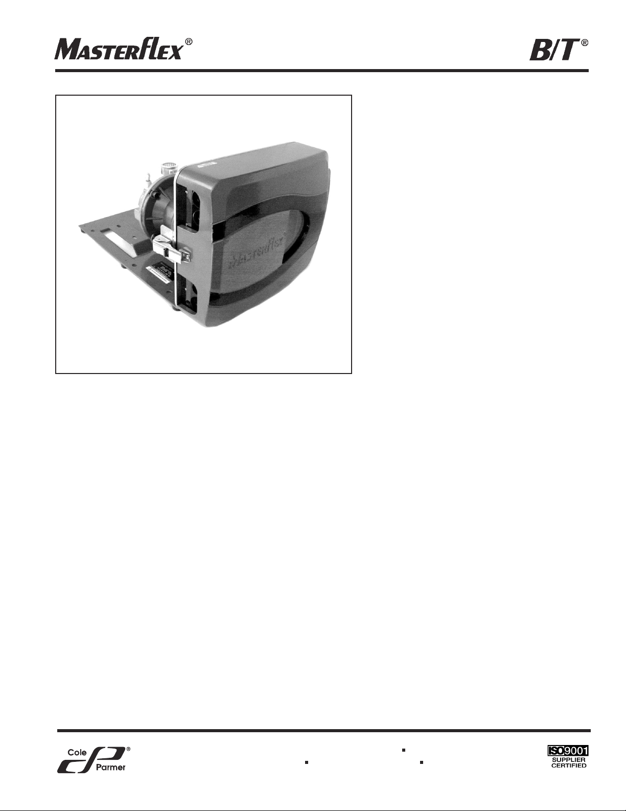
RAPID-LOAD
AIR-POWERED
PERISTALTIC PUMP
AND DRIVE
MASTERFLEX®B/T®Pump 77110-80
Model Numbers
77110-80
A-1299-5123
Edition 01
1-800-MASTERFLEX (627-8373) (U.S. and Canada only)
11 (847) 549-7600 (Outside U.S.) (847) 549-7600 (Local) www.masterex.com
Page 2

2
TABLE OF CONTENTS
Title Page
SAFETY PRECAUTIONS . . . . . . . . . . . . . . . . . . . . . . . . . . . . . . . . . . . . . . . . . . . . . . . . . . . . . . . . . . . . . . . . . . . . . . .3
INTRODUCTION . . . . . . . . . . . . . . . . . . . . . . . . . . . . . . . . . . . . . . . . . . . . . . . . . . . . . . . . . . . . . . . . . . . . . . . . . . . . . .4
APPLICATION DATA . . . . . . . . . . . . . . . . . . . . . . . . . . . . . . . . . . . . . . . . . . . . . . . . . . . . . . . . . . . . . . . . . . . . . . . . . . .4
GENERAL DESCRIPTION . . . . . . . . . . . . . . . . . . . . . . . . . . . . . . . . . . . . . . . . . . . . . . . . . . . . . . . . . . . . . . . . . . . . . .4
SETUP AND OPERATION . . . . . . . . . . . . . . . . . . . . . . . . . . . . . . . . . . . . . . . . . . . . . . . . . . . . . . . . . . . . . . . . . . . . . .6
Load Tubing . . . . . . . . . . . . . . . . . . . . . . . . . . . . . . . . . . . . . . . . . . . . . . . . . . . . . . . . . . . . . . . . . . . . . . . . . . . . . . .6
Pump Mounting Dimensions . . . . . . . . . . . . . . . . . . . . . . . . . . . . . . . . . . . . . . . . . . . . . . . . . . . . . . . . . . . . . . . . . .6
TUBING TYPES . . . . . . . . . . . . . . . . . . . . . . . . . . . . . . . . . . . . . . . . . . . . . . . . . . . . . . . . . . . . . . . . . . . . . . . . . . . . . .7
FLOW RATE . . . . . . . . . . . . . . . . . . . . . . . . . . . . . . . . . . . . . . . . . . . . . . . . . . . . . . . . . . . . . . . . . . . . . . . . . . . . . . . . .7
INSTALLING THE PUMP TUBING . . . . . . . . . . . . . . . . . . . . . . . . . . . . . . . . . . . . . . . . . . . . . . . . . . . . . . . . . . . . . . . .8
REPLACING ROLLERS . . . . . . . . . . . . . . . . . . . . . . . . . . . . . . . . . . . . . . . . . . . . . . . . . . . . . . . . . . . . . . . . . . . . . . . .9
MAINTENANCE . . . . . . . . . . . . . . . . . . . . . . . . . . . . . . . . . . . . . . . . . . . . . . . . . . . . . . . . . . . . . . . . . . . . . . . . . . . . . .9
Recommended Lubricants . . . . . . . . . . . . . . . . . . . . . . . . . . . . . . . . . . . . . . . . . . . . . . . . . . . . . . . . . . . . . . . . . . .9
Cleaning . . . . . . . . . . . . . . . . . . . . . . . . . . . . . . . . . . . . . . . . . . . . . . . . . . . . . . . . . . . . . . . . . . . . . . . . . . . . . . . . .9
Drain Operation . . . . . . . . . . . . . . . . . . . . . . . . . . . . . . . . . . . . . . . . . . . . . . . . . . . . . . . . . . . . . . . . . . . . . . . . . . . .9
Troubleshooting . . . . . . . . . . . . . . . . . . . . . . . . . . . . . . . . . . . . . . . . . . . . . . . . . . . . . . . . . . . . . . . . . . . . . . . . . . . .9
Replacement Parts . . . . . . . . . . . . . . . . . . . . . . . . . . . . . . . . . . . . . . . . . . . . . . . . . . . . . . . . . . . . . . . . . . . . . . . .10
ACCESSORIES . . . . . . . . . . . . . . . . . . . . . . . . . . . . . . . . . . . . . . . . . . . . . . . . . . . . . . . . . . . . . . . . . . . . . . . . . . . . .10
SPECIFICATIONS . . . . . . . . . . . . . . . . . . . . . . . . . . . . . . . . . . . . . . . . . . . . . . . . . . . . . . . . . . . . . . . . . . . . . . . . . . .11
WARRANTY . . . . . . . . . . . . . . . . . . . . . . . . . . . . . . . . . . . . . . . . . . . . . . . . . . . . . . . . . . . . . . . . . . . . . . . . . . . . . . . .12
PRODUCT RETURN . . . . . . . . . . . . . . . . . . . . . . . . . . . . . . . . . . . . . . . . . . . . . . . . . . . . . . . . . . . . . . . . . . . . . . . . .12
TECHNICAL ASSISTANCE . . . . . . . . . . . . . . . . . . . . . . . . . . . . . . . . . . . . . . . . . . . . . . . . . . . . . . . . . . . . . . . . . . . .12
B/T, PERFECTPOSITION – Reg TM Barnant Company
C-FLEX – Reg TM Consolidated Polymer Technologies, Inc.
NORPRENE, PHARMAPURE, PHARMED and TYGON – Reg TM Saint-Gobain Performance Plastics.
TEFLON – Reg TM E.I. DuPont de Nemours and Company
Trademarks bearing the ® symbol in this publication are registered in the U.S. and in other countries.
Page 3
3
SAFETY PRECAUTIONS
WARNINGS: Tubing breakage may result in fluid being sprayed from pump. Use appropriate measures to
protect operator and equipment.
The air supply must be disconnected from pump before removing or installing tubing. Fingers
or loose clothing could get caught in drive mechanism. Do not operate this pump without
cover or interlock door properly closed and latched. Rotating parts can cause serious injury.
To reduce risk of injury, do not pump materials hotter than 150 degrees Fahrenheit, (65.5°C).
CAUTION: Do not exceed 321 rpm. Speeds in excess of 321 rpm may cause damage to the unit.
Do not attempt to use other materials in lieu of recommended tubing, as pump performance
could be severly compromised with possible damage to the pump.
Periodically examine bearings and moving parts for excessive wear that can cause overheating of surfaces from friction.
Select tubing for chemical compatibility. Ground or electrically bond containers during fluid
transfer to avoid electrostatic charge buildup that can ignite vapors when discharged. Refer to
NFPA 77.
WARNING: Risk of Ignition. Periodically examine bearings and moving par ts for excessive wear that can
cause overheating of surfaces from friction. Ground or electrically bond containers during
fluid transfer to avoid electrostatic charge buildup that can ignite vapors when discharged.
Explanation of Symbols
CAUTION: Risk of Danger. Consult Operator’s manual for nature of hazard and corrective actions.
CAUTION: Risk of crushing. Keep fingers away from rotor while pump is in operation. Stop pump before
loading or unloading tubing.
CAUTION: Hot Surface. Do not touch.
WARNING: PRODUCT USE LIMITATION
This product is not designed for, nor intended for use in, patient-connected applications, including, but not limited
to, medical and dental use, and, accordingly, has not been submitted for FDA approval. If drive is used in a manner
not specified in this manual the protection provided by the equipment may be impaired.
ATEX Rating: The models are rated as Group II, Category 3 (Zone 2)
equipment using constructional safety (c) protection, with a T6 (<85° C)
temperature classification for use in Gas Group IIC (acetylene)
environments:
CE <εχ> II 3 G c IIC T6
Page 4
INTRODUCTION
This manual provides information for installing, operating, and servicing the MASTERFLEX®B/T®RAPID-LOAD
®
Air-Powered Variable Occlusion Peristaltic Pump and Drive.
The unique design of the peristaltic pump provides a greatly simplified means for rapid loading and changing of
tubing. In addition, the following features are incorporated:
• Pumps up to 10 GPM (37.8 LPM).
• Uses continuous tubing to ensure a sanitary and non-contaminating system.
• Fluid contacts only the tubing.
• Handles a wide range of viscosities.
• Several different size tubing and formulations can be used.
APPLICATION DATA
The gentle peristaltic action of this pump is ideal for pumping highly viscous and shear-sensitive liquids. These pumps
are also ideally suited for use where sterile conditions and purity are required. Toxic and hazardous fluids can be
pumped with the proper selection of MASTERFLEX
PERFECTPOSITION
B/T tubing since the fluid contacts only the
tubing and not the pump.
WARNING:Tubing breakage may result in fluid being sprayed from pump. Use appropriate measures to pro-
tect operator and equipment.
GENERAL DESCRIPTION
The B/T RAPID-LOAD peristaltic pump (see Figure 1) is mounted on a base and attached to a NEMA 56C frame air
motor through a 5.45:1 gear head.
The maximum recommended rotor speed is 321 rpm. The 321 rpm speed is obtained from the standard 3/4 hp air
motor through the 5.45:1 gear head. Faster speeds increase flow, but also considerably shorten average tubing life.
(We cannot be responsible for pump performance when operated at speeds higher than 321 rpm.)
If the pump is to be operated with back-pressure on the discharge line greater than 5 psig, hose clamps or screw-type
band clamps are recommended on the tubing connections on the discharge side of the pump. Because of their highly
elastic nature, Silicone or C-FLEX®tubing can expand very quickly if back-pressure is present and could create leakage at the fittings if not securely retained. It is this same elastic nature, however, that makes them such excellent
materials for this peristaltic pump. NORPRENE®FOOD, PHARMED®BPJ, and TYGON®LFL tubing yields longer life,
especially under pressure. Refer to Table 1 for tubing recommendations.
CAUTION: Do not attempt to use other materials in lieu of recommended tubing, as pump performance
could be severely compromised with possible damage to the pump.
4
Page 5

5
Figure 1. AIR-POWERED Rapid-Load Pump and Drive
Figure 2. RAPID-LOAD PUMP ASSEMBLY
ROTOR ASSEMBLY
DOOR ASSEMBLY
ROLLER
RETAINER ASSEMBLY
OCCLUSION BED
FILTER/REGULATOR
CONTROL KNOB
(SPEED CONTROL)
MUFFLER
LUBRICATOR
CONTROL KNOB
DOOR
ASSEMBLY
GEAR
REDUCER
ELBOW PIPE
NIPPLE
PRESSURE
GAUGE
BASE
AIR
MOTOR
Page 6

6
SETUP AND OPERATION
This unit should be placed on a flat surface such as a floor, bench, or table and should be near a compressed air
source.
Unpack the drive and save packaging material until proper product operation has been verified.
Install the following components: pressure gauge, pressure filter/regulator and lubricator assembly, pipe nipple,
elbow, and muffler. See Figure 1 for proper or ientation, (all items and fittings included except as noted). Use a thread
seal such as TEFLON®tape for all connections to reduce the possibility of air leakage.
Load Tubing (See 3 & 4)
Connect compressed air line to the 1/4 NPT (F) connection on the regulator (fitting not supplied). Turn on compressed
air line to start pumping. (Maximum 100 psig inlet.)
NOTE: Pump will not run unless Door Assembly is closed.
Adjust flow rate with adjustment knob on top of regulator. Vary flow rate from 20 psig to 100 psig. At higher pressures,
the pump speed may exceed 321 rpm.
CAUTION: Do not exceed 321 rpm. Speeds in excess of 321 rpm may cause damage to unit.
(Lock flow rate by using snap-action push-pull knob on filter regulator.) For continuous-duty or high-speed application,
use of the lubricator is recommended. Adjust the lubricator with the adjustment knob on top. For higher speeds, set
lubricator to provide 1–3 drops/minute. Use a lower setting for lower speeds. See MAINTENANCE for RECOMMENDED LUBRICANTS. (Lock lubrication rate by using snap-action push-pull knob.)
Pump Mounting Dimensions
Page 7

7
TUBING TYPES
Use only MASTERFLEX
PERFECTPOSITION
B/T precision tubing with MASTERFLEX pumps to ensure
optimum performance.
Use of other tubing may void applicable warranties.
NOTE: Use MASTERFLEX
PERFECTPOSITION
B/T tubing. These pumps are designed to use B/T tubing sizes
87 and 91 only. The tubing sizes refer to the last two digits of the MASTERFLEX
PERFECTPOSITION
B/T
tubing model number.
The following chart provides information for the various sizes of tubing.
Tubing Size
Characteristics B/T 87 B/T 91
Inside Dia. in (mm) 0.5 (12.7) 0.75 (19.05)
Outside Dia. in (mm) 1.0 (25.4) 1.25 (31.8)
Hose barb size in (mm) 1/2″ (12.7) 3/4″ (19.0)
Flow Range 0.17-5.0 GPM (0.010-18.9 L/m) 0.37-10 GPM (1.40-37.85 L/m)
(with 321 rpm drive)
Nominal Flow Per Revolution 70.46 mL 141 mL
Maximum Vacuum 28.5 in Hg 32 in Hg
Maximum: Outlet Pressure 35 psi 30 psi
Flow ranges are approximate - calculated under the following conditions: 0 psi at inlet, 0.5 psi at outlet and water
circulant at 72°F (22° C).
Table 1
FLOW RATE
For indirect estimate of flow rate, a reflective element attached to a rotor has been provided for use with an optical
tachometer. Point optical tachometer beam through front cover window and target reflective element.
To obtain flow rate in mL/min, multiply tachometer rpm reading by the nominal flow per revolution value provided in
TABLE 1.
NOTE: 3,785 mL = 1 U.S. liquid gallon.
Page 8

INSTALLING THE PUMP TUBING
WARNING: The air supply must be disconnected from pump before removing or installing tubing. Fingers
or loose clothing could get caught in drive mechanism. Do not operate this pump without
cover or interlock door properly closed and latched. Rotating parts can cause serious injury.
1. Disconnect air supply to the pump.
2. Unlatch the locking clamp and open the cover.
3. Insert the tube in the appropriate tube retaining pocket (see Figure 3). Line up the “
PERFECTPOSITION
” place-
ment marks printed on the tube with the outside edge of the retainer assembly (see Figure 4).
4. Wrap the tubing around the rotor assembly and insert the tubing in the lower retaining pocket.
5. Close the cover and re-latch the locking clamp.
6. Restore air source to the pump.
7. Turn the motor on.
8
Figure 2. TUBING RETAINING POCKETS
Figure 3. PERFECTPOSITION MARKS
PERFECTPOSITION
MARK
PERFECTPOSITION
MARKS
Page 9

9
REPLACING ROLLERS
To replace rollers:
1. Using a retaining ring tool (Part Number 07585-06),
remove the retaining rings from the ends of the roller
axles and slide the rollers off. Take care to avoid
opening the retaining rings too wide.
2. Check to be sure that the wave washers are installed
on the axles against the rotor plate.
3. Slide the new rollers, Replacement Roller Kit 07584-02,
onto the axles, placing the ends with the flush bearing
surface inward toward the rotor plate against the wave
washers, and the etched ends with the recessed
bearing surface outward toward the free ends of the
roller axles.
4. Replace the retaining rings. You may have to push the
rollers in to compress the wave washers to allow the
retaining rings to engage the grooves in the axles.
EXPLODED ROLLER SUB-ASSEMBLY
MAINTENANCE
The air motor is a rotary vane type motor. Lubrication is necessary for the bearings, shaft seals, and rust prevention.
Excessive moisture in the air line can cause rust formation in the motor and can cause ice to form in the muffler due
to expansion of air through the motor.
Recommended Lubricants
Use a misting type oil rated 50 to 200 SSU (ISO Grade 7 to 46) at 100°F (38°C). Unscrew the bowl to fill the lubricator. Press up on the bottom drain to empty bowl.
Cleaning
Keep the drive enclosure clean with mild detergents. Never immerse nor use excessive fluid.
Drain Operation
The filter/regulator assembly has a manual drain. Check it frequently for water accumulation. Open drain by pressing
up on bottom of bowl.
Troubleshooting
If drive does not operate, disconnect air supply:
a. Check pump head for tubing jam.
b. Check lubricant level.
c. Reconnect air supply and check air supply.
Contact your dealer for further service needs.
Page 10

Replacement Parts
The following list identifies the replaceable parts and includes the part numbers.
Description Part Number Qty per Unit
Replacement air motor 108288-CR 1
Replacement regulator/lubricator 07042-85 1
Rubber Feet Kit (w/screws) 108655-CR 6
MASTERFLEX B/T
Roller Kit 07584-02 1
MASTERFLEX B/T
Rotor Assembly/with rollers 108024-CR 1
Shoulder Spacer Kit 108013-CR 3
Door Assembly 108175-CR 1
Window 108179-CR 1
Window Gasket 108183-CR 1
Safety Switch Assy 108173-CR 1
ACCESSORIES
All MASTERFLEX
PERFECTPOSITION
B/T tubing formulations in sizes 87 and 91 can be used with this pump. Be
sure tubing material matches application.
Description Part Number
Retaining Ring Tool 07585-06
PERFECT POSITION Pump Tubing B/T 87 B/T 91
Silicone - 10 ft. (3.0 m), Platinum cured 96510-87 96510-91
Silicone - 10 ft. (3.0 m), Peroxide cured 96400-87 96400-91
BioPharm silicone - 25 ft. (7.6 m), Platinum cured 96422-87 96422-91
BioPharm Plus silicone - 25 ft. (7.6 m), Platinum cured 96442-87 96442-91
C-FLEX - 10 ft. (3.0 m) 06424-87 06424-91
PharMed®BPT - 25 ft. (7.6 m) 06508-87 06508-91
PharMed®BPT - 3 ft. (0.9 m) 95668-87 95668-91
PharmaPure®- 25 ft. (7.6 m) 06435-87 06435-91
Norprene®food - 25 ft. (7.6 m) 06402-87 06402-91
Norprene®food - 3 ft. (0.9 m) 06403-87 06403-91
TYGON®LFL - 25 ft. (7.6 m) 06429-87 06429-91
TYGON®LFL - 3 ft. (0.9 m) 06430-87 06430-91
10
Page 11

11
SPECIFICATIONS
Output:
Pump Speed: 35 to 321 rpm
Torque output, maximum: 1100 oz-in (104 kg-cm)
Tubing compatibility: Sizes 87 and 91
Flow Range: up to 10 GPM (37.8 LPM)
Input:
Compressed air: 24 cfm (0.68 m
3
/min) @ 100 psig
Construction:
Dimensions: 16.75 in W × 11.75 in H × 21 in D
(42.5 cm W × 29.8 cm H × 53.3 cm D)
Weight: 63 lbs (28.5 kg)
Enclosure Rating: IP56 per IEC 60529
Environment:
Operating Temperature: 1°C to 40°C (34°F to 104°F)
Storage Temperature: –10°C to 65°C (–14°F to 149°F)
Humidity:
(non-condensing) 20% to 80%
Altitude: Less than 2000 m
Atex Rating: CE <
εχ> II 3 G c IIC T6
Group: II (Non-mining equipment)
Category: 3 (No ignition source)
Zone: 2 (Infrequent exposure)
Type of Atmosphere: G (Gas)
Gas Group IIC (Hydrogen/Acelylene)
Method of Protection: “C” (Non-electrical equipment construction)
Temperature Classification: T6 (85°C max. surface temperature)
Chemical Resistance: Exposed materials are powder coated aluminum, CRS, plastic, and vinyl
Compliance (for CE mark): EN809 (EU Machine Directive)
EN13463-1 and EN13463-5 (EU Atex Directive)
Page 12

12
WARRANTY
Use only MASTERFLEX
PERFECTPOSITION
B/T precision tubing with MASTERFLEX pumps to ensure
optimum performance. Use of other tubing may void applicable warranties.
The Manufacturer warrants this product to be free from significant deviations from published specifications. If repair or
adjustment is necessary within the warranty period, the problem will be corrected at no charge if it is not due to misuse or abuse on your part, as determined by the Manufacturer. Repair costs outside the warranty period, or those
resulting from product misuse or abuse, may be invoiced to you.
The warranty period for this product is noted on the Warranty Card.
PRODUCT RETURN
To limit charges and delays, contact the seller or Manufacturer for authorization and shipping instructions before
returning the product, either within or outside of the warranty period. When returning the product, please state the reason for the return. For your protection, pack the product carefully and insure it against possible damage or loss. Any
damages resulting from improper packaging are your responsibility.
TECHNICAL ASSISTANCE
If you have any questions about the use of this product, contact the Manufacturer or authorized seller.
We reserve the right to make improvements in design, construction, and appearance of our products without notice.
Printed in U.S.A.
625 East Bunker Court
Vernon Hills, Illinois U.S.A. 60061-1844
1-800-MASTERFLEX (627-8373) (U.S. and Canada only)
11 (847) 549-7600 (outside U.S.)
(847) 549-7600 (Local)
FAX (847) 247-2929 (U.S. and Canada only)
11 (847) 549-1700 (Fax outside U.S.)
www.masterflex.com
e-mail: techinfo@coleparmer.com
 Loading...