

Page 1

OPERATING MANUAL:
B/T®RAPID-LOAD
PERISTALTIC PUMPS
AND DRIVE
MASTERFLEX®B/T®Pump 77110-60
Model Numbers
77110-60
77110-67
1-800-MASTERFLEX (627-8373) (U.S. and Canada only)
䡲
11 (847) 549-7600 (Outside U.S.)䡲(847) 549-7600 (Local)䡲www.masterflex.com
A-1299-5122
Edition 01
Page 2

2
TABLE OF CONTENTS
Title Page
SAFETY PRECAUTIONS . . . . . . . . . . . . . . . . . . . . . . . . . . . . . . . . . . . . . . . . . . . . . . . . . . . . . . . . . . . . . . . . . . . . . . .3
INTRODUCTION . . . . . . . . . . . . . . . . . . . . . . . . . . . . . . . . . . . . . . . . . . . . . . . . . . . . . . . . . . . . . . . . . . . . . . . . . . . . . .4
APPLICATION DATA . . . . . . . . . . . . . . . . . . . . . . . . . . . . . . . . . . . . . . . . . . . . . . . . . . . . . . . . . . . . . . . . . . . . . . . . . . .4
GENERAL DESCRIPTION . . . . . . . . . . . . . . . . . . . . . . . . . . . . . . . . . . . . . . . . . . . . . . . . . . . . . . . . . . . . . . . . . . . . . .5
INSTALLATION AND SETUP . . . . . . . . . . . . . . . . . . . . . . . . . . . . . . . . . . . . . . . . . . . . . . . . . . . . . . . . . . . . . . . . . . . .6
Pump Mounting Dimensions . . . . . . . . . . . . . . . . . . . . . . . . . . . . . . . . . . . . . . . . . . . . . . . . . . . . . . . . . . . . . . . . . .7
TUBING TYPES . . . . . . . . . . . . . . . . . . . . . . . . . . . . . . . . . . . . . . . . . . . . . . . . . . . . . . . . . . . . . . . . . . . . . . . . . . . . . .7
INSTALLING THE PUMP TUBING . . . . . . . . . . . . . . . . . . . . . . . . . . . . . . . . . . . . . . . . . . . . . . . . . . . . . . . . . . . . . . . .8
REPLACING ROLLERS . . . . . . . . . . . . . . . . . . . . . . . . . . . . . . . . . . . . . . . . . . . . . . . . . . . . . . . . . . . . . . . . . . . . . . . .9
OPERATION . . . . . . . . . . . . . . . . . . . . . . . . . . . . . . . . . . . . . . . . . . . . . . . . . . . . . . . . . . . . . . . . . . . . . . . . . . . . . . . .9
MAINTENANCE . . . . . . . . . . . . . . . . . . . . . . . . . . . . . . . . . . . . . . . . . . . . . . . . . . . . . . . . . . . . . . . . . . . . . . . . . . . . .10
Replacement Parts . . . . . . . . . . . . . . . . . . . . . . . . . . . . . . . . . . . . . . . . . . . . . . . . . . . . . . . . . . . . . . . . . . . . . . . .11
Cleaning . . . . . . . . . . . . . . . . . . . . . . . . . . . . . . . . . . . . . . . . . . . . . . . . . . . . . . . . . . . . . . . . . . . . . . . . . . . . . . . .11
ACCESSORIES . . . . . . . . . . . . . . . . . . . . . . . . . . . . . . . . . . . . . . . . . . . . . . . . . . . . . . . . . . . . . . . . . . . . . . . . . . . . .12
SPECIFICATIONS . . . . . . . . . . . . . . . . . . . . . . . . . . . . . . . . . . . . . . . . . . . . . . . . . . . . . . . . . . . . . . . . . . . . . . . . . . .13
WARRANTY . . . . . . . . . . . . . . . . . . . . . . . . . . . . . . . . . . . . . . . . . . . . . . . . . . . . . . . . . . . . . . . . . . . . . . . . . . . . . . . .16
PRODUCT RETURN . . . . . . . . . . . . . . . . . . . . . . . . . . . . . . . . . . . . . . . . . . . . . . . . . . . . . . . . . . . . . . . . . . . . . . . . .16
TECHNICAL ASSISTANCE . . . . . . . . . . . . . . . . . . . . . . . . . . . . . . . . . . . . . . . . . . . . . . . . . . . . . . . . . . . . . . . . . . . .16
B/T, PERFECTPOSITION – Reg TM Barnant Co.
C-FLEX – Reg TM Consolidated Polymer Technologies, Inc.
NORPRENE, PHARMAPURE, PHARMED and TYGON – Reg TM Saint-Gobain Performance Plastics
Trademarks bearing the ® symbol in this publication are registered in the U.S. and in other countries.
Page 3
SAFETY PRECAUTIONS
DANGER: High voltages exist and are accessible. Do not remove cover of Drive or Controller. Use
extreme caution when servicing internal components.
CAUTIONS: Risk of electric shock – this pump is supplied with a grounding conductor and grounding-type
attachment plug. To reduce risk of electric shock, be certain that it is connected only to a
properly grounded, grounding-type receptacle.
Electrical connections and grounding (earthing) must conform to local wiring codes.
WARNINGS: Tubing breakage may result in fluid being sprayed from pump. Use appropriate measures to
protect operator and equipment.
To reduce risk of injury, power must be removed from pump before removing or installing
tubing. Fingers or loose clothing could get caught in drive mechanism. Do not operate this
pump without cover or interlock door properly closed and latched. Rotating parts can cause
serious injury.
To reduce risk of injury, do not pump materials hotter than 150 degrees Fahrenheit, (65.5°C).
Explanation of Symbols
CAUTION: Risk of Danger. Consult Operator’s manual for nature of hazard and corrective actions.
CAUTION: Risk of crushing. Keep fingers away from rotor while pump is in operation. Stop pump before
loading or unloading tubing.
CAUTION: Hot Surface. Do not touch.
CAUTION: Risk of electric shock. Consult Operator’s manual for nature of hazard and corrective actions.
WARNING: PRODUCT USE LIMITATION
This product is not designed for, nor intended for use in, patient-connected applications, including, but not limited
to, medical and dental use, and, accordingly, has not been submitted for FDA approval. If drive is used in a manner
not specified in this manual the protection provided by the equipment may be impaired.
3
Page 4

INTRODUCTION
This manual provides information for installing, operating and servicing the following models of MASTERFLEX®B/T
®
RAPID-LOAD®Peristaltic Pumps and Drive.
MODEL TYPE
77110-60 Pump with variable speed washdown motor and IP56 controller, 115V AC system.
77110-67 Pump with variable speed washdown motor and IP56 controller, 230V AC system.
The unique design of these peristaltic pumps provides a greatly simplified means for rapid loading and changing of
tubing. In addition, the following features are incorporated:
Pumps up to 10 GPM.
Uses continuous tubing to ensure a sanitary and non-contaminating system.
Fluid contacts only the tubing.
Handles wide range of viscosities.
Several different size tubing and formulations can be used.
Washdown motor and IP56 controller is provided.
APPLICATION DATA
The gentle peristaltic action of these pumps is ideal for pumping highly viscous and shear-sensitive liquids. These
pumps are also ideally suited for use where sterile conditions and purity are required. Toxic and hazardous fluids can
be pumped with the proper selection of MASTERFLEX
PERFECTPOSITION
B/T tubing since the fluid contacts only
the tubing and not the pump.
WARNING: Tubing breakage may result in fluid being sprayed from pump. Use appropriate measures to
protect operator and equipment.
Page 5

5
GENERAL DESCRIPTION
The RAPID-LOAD®B/T peristaltic pump (see Figure 1) is mounted on a base and attached to a NEMA 56C frame
motor or IEC-72 71-14F130 frame motor (with foot mountings) through a 5.45:1 gear head and adapter. Depending
on the model, the motor is either supplied or customer furnished and is attached to the adapter by four bolts and to
the base by an additional four bolts. The controller is mounted on a bracket above the gear head. The bracket and
controller can be removed and hung by two bolts at a location up to 10 ft. away. The controller incorporates a
REV-OFF-FWD switch and a speed control.
Due to its unique design, different MASTERFLEX
PERFECTPOSITION
B/T tubing sizes can be accommodated by
this RAPID-LOAD peristaltic pump.
For an indirect estimate of flow rate, a reflective element attached to the rotor has been provided for use with an
optical tachometer. Point tachometer beam through front cover window and target the reflective element.
To obtain flow rate in mL/min., multiply tachometer rpm reading times the nominal flow per revolution value provided in
TABLE 1 (Note: 3,785 mL = 1 U.S. liquid gallon).
The maximum recommended rotor speed is 321 rpm. The pump rotor can turn either clockwise or counterclockwise.
When turning clockwise (FWD) the top connection is for suction and the bottom connection is for discharge. The
321 rpm speed is obtained from the standard 1725 rpm fractional horsepower motor through the 5.45:1 gear
reduction. Faster speeds will increase flow, but will also considerably shorten average tubing life. (We cannot be
responsible for pump performance when operated at speeds higher than 321 rpm.)
Figure 1. RAPID-LOAD PUMP AND DRIVE
Page 6
6
If the pump is to be operated with back-pressure on the discharge line greater than 5 PSIG, hose clamps or
screw-type band clamps are recommended on the tubing connections on the discharge side of the pump. Silicone or
C-FLEX®tubing, because of their highly elastic natures, can expand very quickly if back-pressure is present and could
create leakage at the fittings if not securely retained. It is this same elastic nature, however, that makes them such
excellent materials for this peristaltic type pump. NOPRENE
®
tubing yields longer life, especially under pressure. Do
not attempt to use other materials in lieu of these, as pump performance could be severely compromised with possible
damage to the pump. Refer to Table 1 for tubing recommendations.
INSTALLATION AND SETUP
These units should be placed on a flat surface such as a floor, bench or table and should be near an electrical power
source. Be sure to check data plate for proper voltage rating(s).
NOTE: The controller and bracket can be removed and located up to 10 feet away. Secure the bracket using two bolts
inserted through the keyhole slots.
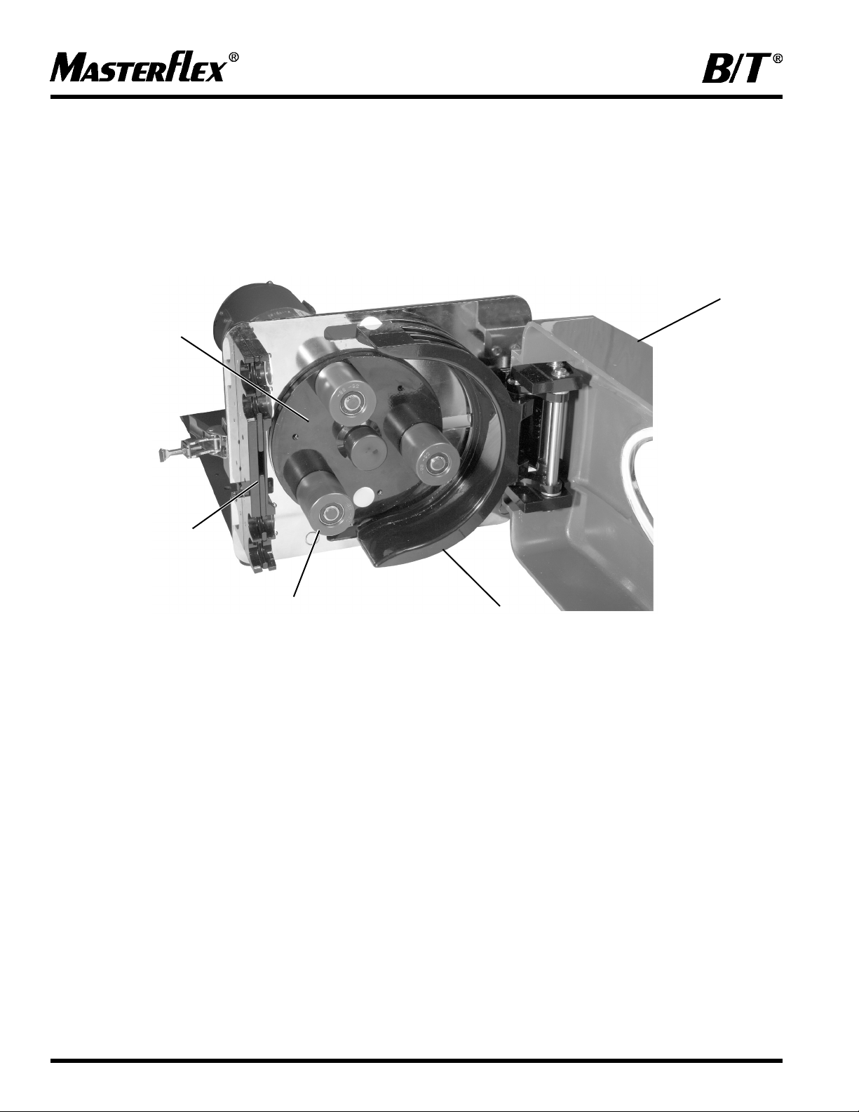
Figure 2. RAPID-LOAD PUMP AND DRIVE
ROTOR ASSEMBLY
DOOR ASSEMBLY
ROLLER
RETAINER ASSEMBLY
OCCLUSION BED
Page 7

7
TUBING TYPES
Use only MASTERFLEX
PERFECTPOSITION
B/T precision tubing with MASTERFLEX pumps to ensure
optimum performance.
Use of other tubing may void applicable warranties.
NOTE: Use MASTERFLEX
PERFECTPOSITION
B/T tubing. These pumps are designed to use
PERFECTPOSITION
B/T tubing sizes 87 and 91 only. The tubing sizes refer to the last two digits of the MASTERFLEX
PERFECT-
POSITION
B/T tubing model number.
The following chart provides information for the various sizes of tubing.
Tubing Size
Characteristics B/T 87 B/T 91
Inside Dia. in (mm) 0.5 (12.7) 0.75 (19.05)
Outside Dia. in (mm) 1.0 (25.4) 1.25 (31.8)
Hose barb size in (mm) 1/2″ (12.7) 3/4″ (19.0)
Flow Range 0.17-5.0 GPM (0.010-18.9 L/m) 0.37-10 GPM (1.40-37.85 L/m)
(with 321 rpm drive)
Nominal Flow Per Revolution 70.46 mL 141 mL
Maximum Vacuum 28.5 in Hg 32 in Hg
Maximum: Outlet Pressure 35 psi 30 psi
Flow ranges are approximate - calculated under the following conditions: 0 psi at inlet, 0.5 psi at outlet and water
circulant at 72°F (22° C).
Table 1
PUMP MOUNTING
DIMENSIONS
MODEL NOS. 77110-60, 77110-67
Page 8

8
Figure 2. TUBING RETAINING POCKETS
Figure 3. PERFECTPOSITION MARKS
INSTALLING THE PUMP TUBING
WARNING: Power must be removed from pump before removing or installing tubing. Fingers or loose
clothing could get caught in drive mechanism. Do not operate this pump without cover or
interlock door properly closed and latched. Rotating parts can cause serious injury.
1. Cut off power to the pump by disconnecting line cord or, if wired permanently, by removing the fuse. Do not
assume that turning off the switch at the motor (or controller) is "safe enough."
2. Unlatch the locking clamp and open the cover.
3. Insert the tube in the appropriate upper tube retaining pocket (see Figure 2). Line up the “
PERFECTPOSITION
”
placement marks printed on the tube with the outside edge of the retainer assembly (see Figure 3).
4. Wrap the tubing around the rotor assembly and insert the tubing in the lower retaining pocket.
5. Close the cover and re-latch the locking clamp.
6. If the new tube must be cut from a length of approved replacement tubing, a minimum of 32 inches will be required
for a new tube.
WARNING: Do not operate this pump without cover or interlock door properly closed and latched.
Rotating parts can cause serious injury.
7. Restore power to the pump.
NOTE: Under some circumstances, tubing may creep into pump. If this problem occurs it can be remedied by
installing a hose clamp or fitting immediately upstream of the upper retaining pocket.
PERFECTPOSITION
MARK
PERFECTPOSITION
MARKS
Page 9

REPLACING ROLLERS
To replace rollers:
1. Using a retaining ring tool (Part Number 07585-06),
remove the retaining rings from the ends of the roller
axles and slide the rollers off. Take care to avoid
opening the retaining rings too wide.
2. Check to be sure that the wave washers are installed
on the axles against the rotor plate.
3. Slide the new rollers onto the axles, placing the ends
with the flush bearing surface inward toward the rotor
plate against the wave washers, and the etched ends
with the recessed bearing surface outward toward the
free ends of the roller axles.
4. Replace the retaining rings. You may have to push the
rollers in to compress the wave washers to allow the
retaining rings to engage the grooves in the axles.
EXPLODED ROLLER SUB-ASSEMBLY
OPERATION
Controller:
Models 77110-60 (115V model) and 77110-67 (230 V model)
are supplied with an electronic controller (see Figure 4) for
controlling pump speed.
1. Place FWD-OFF-REV switch in the desired position,
clockwise (FWD) or counterclockwise (REV) direction.
2. Adjust SPEED control for the desired pump speed.
Figure 4. CONTROLLER
9
Page 10

10
MAINTENANCE
Tools Required: Phillips screwdriver
Motor Brush Replacement Models 77110-60 and 77110-67
WARNING: Power must be removed from motor before performing this procedure.
1. Cut off power to the pump by disconnecting line cord or, if wired permanently, by removing the fuse. Do not
assume that turning off the switch at the motor (or controller) is "safe enough."
2. To access the motor brushes, remove six screws securing the access plate and remove plate (see Figure 5).
3. Loosen screw terminal at top of brush housing and disconnect brush wire.
4. Press down on brush retainer to disengage tabs then rotate brush retainer slightly toward front of motor and
remove brush retainer.
5. Slide brush assembly out of housing.
6. Install new brush assembly with brush wire toward rear of motor and spring assembly on top.
7. Inser t brush retainer against brush springs and push down, then rotate retainer slightly toward rear of motor to
engage tabs of retainer under rear edge of brush housing.
8. Attach brush wire to screw terminal at top of brush housing. Be sure wire is clear of access opening.
9. Attach cover plate with six screws.
Note: Always replace both brushes at the same time.
Page 11

11
Figure 5. MOTOR BRUSH
Replacement Parts
The following list identifies the replaceable parts and includes the part numbers.
Description Part Number Qty per Unit
Motor Brush Set A-4156-CR 1
(applicable to both models)
Door Assembly 108175-CR 1
Rubber Feet Kit (6 screws) 108655-CR 6
MASTERFLEX B/T
Roller Kit 07584-02 1
MASTERFLEX B/T
Rotor Assembly/with Rollers 108024-CR 1
Window 108179-CR 1
Window Gasket 108183-CR 1
Shoulder Spacer Kit 108013-CR 3
Safety Switch Assy 108173-CR 1
Cleaning
Keep the drive enclosure clean with mild detergents. Never immerse nor use excessive fluid.
Page 12

12
ACCESSORIES
All MASTERFLEX
PERFECTPOSITION
B/T tubing formulations in sizes 87 and 91 can be used with this pump. Be
sure tubing material matches application.
Description Part Number
Retaining Ring Tool 07585-06
Extension Cable, 25 ft. 108657-CR
PERFECTPOSITION
Pump Tubing B/T 87 B/T 91
Silicone - 10 ft. (3.0 m), Platinum cured 96510-87 96510-91
Silicone - 10 ft. (3.0 m), Peroxide cured 96400-87 96400-91
BioPharm silicone - 25 ft. (7.6 m), Platinum cured 96422-87 96422-91
BioPharm Plus silicone - 25 ft. (7.6 m), Platinum cured 96442-87 96442-91
C-FLEX - 10 ft. (3.0 m) 06424-87 06424-91
PharMed®BPT - 25 ft. (7.6 m) 06508-87 06508-91
PharMed®BPT - 3 ft. (0.9 m) 95668-87 95668-91
PharmaPure®- 25 ft. (7.6 m) 06435-87 06435-91
NORPRENE®food - 25 ft. (7.6 m) 06402-87 06402-91
NORPRENE®food - 3 ft. (0.9 m) 06403-87 06403-91
TYGON®LFL - 25 ft. (7.6 m) 06429-87 06429-91
TYGON®LFL - 3 ft. (0.9 m) 06430-87 06430-91
Page 13

13
SPECIFICATIONS
Output:
Pump Speed: 12 to 321 rpm
Torque output, maximum: 1100 oz-in (104 kg-cm)
Tubing compatibility: Sizes 87 or 91
Flow Range: Up to 10 GPM (37.85 LPM)
Input:
Supply voltage limits:
Model 77110-60 90 to 130 Vrms @ 60 Hz
Model 77110-67 200 to 260 Vrms @ 50 Hz
Current, max:
Model 77110-60 8A, 1/4″ × 1-1/4″, fast acting
Model 77110-67 5A, 1/4″ × 1-1/4″, fast acting
Construction:
Dimensions:
Model 77110-60
16.5 in W × 14 in H × 22 in D
(41.9 cm W × 35.6 cm H × 55.9 cm D)
Model 77110-67
16.5 in W × 14 in H x 22 in D
(41.9 cm W × 35.6 cm H × 55.9 cm D)
Weight:
Model 77110-60 89 lbs (40.4 kg)
Model 77110-67 89 lbs (40.4 kg)
Enclosure Rating:
Model 77110-60 IP56 per IEC 60529
Model 77110-67 IP56 per IEC 60529
Page 14

14
SPECIFICATIONS (cont.)
Construction (cont.)
Environment:
Operating Temperature: 0°C to 40°C (32°F to 104°F)
Storage Temperature: -20°C to 60°C (-4°F to 140°F)
Humidity:
(non-condensing) 10% to 90%
Altitude: Less than 2000 m
Chemical Resistance: Exposed material is painted aluminum, plastic and vinyl
Compliance: 115V: UL778, CSA C22.2 No. 108
230V: (for CE Mark)
Page 15

15
Notes . . .
Page 16
WARRANTY
Use only MASTERFLEX PERFECTPOSITION B/T precision tubing with MASTERFLEX pumps to ensure
optimum performance. Use of other tubing may void applicable warranties.
The Manufacturer warrants this product to be free from significant deviations from published specifications. If repair or
adjustment is necessary within the warranty period, the problem will be corrected at no charge if it is not due to
misuse or abuse on your part, as determined by the Manufacturer. Repair costs outside the warranty period, or those
resulting from product misuse or abuse, may be invoiced to you.
The warranty period for this product is noted on the Warranty Card.
PRODUCT RETURN
To limit charges and delays, contact the seller or Manufacturer for authorization and shipping instructions before
returning the product, either within or outside of the warranty period. When returning the product, please state the
reason for the return. For your protection, pack the product carefully and insure it against possible damage or loss.
Any damages resulting from improper packaging are your responsibility.
TECHNICAL ASSISTANCE
If you have any questions about the use of this product, contact the Manufacturer or authorized seller.
625 East Bunker Court
Vernon Hills, Illinois U.S.A. 60061-1844
1-800-MASTERFLEX (627-8373) (U.S. and Canada only)
11 (847) 549-7600 (outside U.S.)
(847) 549-7600 (Local)
FAX (847) 247-2929 (U.S. and Canada only)
11 (847) 549-1700 (Fax outside U.S.)
www.masterflex.com
e-mail: techinfo@coleparmer.com
16
Printed in U.S.A.
 Loading...