

Page 1
Color profile: Disabled
Composite Default screen
OPERATING MANUAL
LIQUI-SENSE®CONTROLLERS
MODEL NO. 77096-00
MODEL NO. 77096-05
AND
LIQUI-SENSE®DETECTORS
MODEL NO. 77095-00
MODEL NO. 77095-01
®
ek91.chp
Tue Sep 26 14:32:38 2000
Cole-Parmer Instrument Co.
625 East Bunker Court
Vernon Hills, Illinois U.S.A.60061-1844
(847) 549-7600
(847) 247-2929 (fax)
800-323-4340
www.coleparmer.com
e-mail: techinfo@coleparmer .com
A-1299-0512
Edition 03
Page 2
Color profile: Disabled
Composite Default screen
EU Declaration of Conformity
Name of Apparatus: Liqui-Sense®Controller
Model Numbers: 77096-05
Description of Apparatus: Fluid Monitor System
Barnant Company declares that the above model is in conformity to the following
harmonized standards and directives:
Applicable
Directives
73/23/EEC
93/68/EEC
89/336/EEC
92/31/EEC
93/68/EEC
The last two digitsofthe year in whichthe current configurationof the above models
was assessed per the Low Voltage Directive is:00.
Manufacturer:
Barnant Company Division
Cole-ParmerInstrument Company
28W092 Commercial Avenue
Barrington,IL 60010
USA
Tel.: 847-381-7050
Manufacturer’s Signature:
_________________________ _______________________
JamesW. Doll Date
Vice President, Engineering
Applicable
Specifications
EN61010-1/A2:1995 TR9516
EN61326-1/A1:1998 TR9519
Manufacturer’s
Report Number
22 August, 2000
SAFETY PRECAUTIONS
WARNINGS:
WARNING:
CAUTION:
If the equipment is used in a manner other than as
specified, pr otection provided by the equipment may be
impaired.
No user serviceable parts are inside of this Controller.
Refer servicing to your dealer.
TheLIQUI-SENSE Controllermustbe positioned soleaking liquid will not enter the rear power connectors. Use
of a power line with a Ground Fault Interrupt (GFI) is
recommended.
Use with caustic liquids not compatible with detector
materials voids warranty.
ek91.chp
Tue Sep 26 14:32:39 2000
–i–
Page 3

Color profile: Disabled
Composite Default screen
TABLE OF CONTENTS
Title Page
SAFETYPRECAUTIONS . . . . . . . . . . . . . . . . . . . . . . . . . . . . . . . . . . . . . i
INTRODUCTION . . . . . . . . . . . . . . . . . . . . . . . . . . . . . . . . . . . . . . . . . . . 2
APPLICATIONS . . . . . . . . . . . . . . . . . . . . . . . . . . . . . . . . . . . . . . . . . . . . 3
DESCRIPTION .. ... ... ... ... ... ... ... ... ... ... ... ... ... ... 6
INSTALLATION AND SETUP. . . . . . . . . . . . . . . . . . . . . . . . . . . . . . . . . . 9
OPERATION . . . . . . . . . . . . . . . . . . . . . . . . . . . . . . . . . . . . . . . . . . . . . 13
Operator Control and Indicators. . . . . . . . . . . . . . . . . . . . . . . . . . . . . 13
Startup Procedure . . . . . . . . . . . . . . . . . . . . . . . . . . . . . . . . . . . . . . . 15
Operational Checks . . . . . . . . . . . . . . . . . . . . . . . . . . . . . . . . . . . . . . 15
SENSITIVITY ADJUSTMENT . . . . . . . . . . . . . . . . . . . . . . . . . . . . . . . . 16
MAINTENANCE ANDTROUBLESHOOTING . . . . . . . . . . . . . . . . . . . . 17
Fuse Replacement. . . . . . . . . . . . . . . . . . . . . . . . . . . . . . . . . . . . . . . 17
Cleaning . . . . . . . . . . . . . . . . . . . . . . . . . . . . . . . . . . . . . . . . . . . . . . 17
Troubleshooting . . . . . . . . . . . . . . . . . . . . . . . . . . . . . . . . . . . . . . . . . 18
ACCESSORIES. . . . . . . . . . . . . . . . . . . . . . . . . . . . . . . . . . . . . . . . . . . 19
SPECIFICATIONS . . . . . . . . . . . . . . . . . . . . . . . . . . . . . . . . . . . . . . . . . 20
WARRANTY . ... ... ... ... ... ... ... ... ... ... ... ... ... ... .. 21
PRODUCT RETURN. . . . . . . . . . . . . . . . . . . . . . . . . . . . . . . . . . . . . . . 21
TECHNICAL ASSISTANCE . . . . . . . . . . . . . . . . . . . . . . . . . . . . . . . . . . 21
APPENDIX A: AUXILIARY CABLE CONNECTIONS . . . . . . . . . . . . . 22
Only the Model 77096-00 LIQUI-SENSE Controller is UL and cUL listed.
Trademarksbearing the ® symbol in this publication are registered in the U.S.and in other countries.
–1–
ek91.chp
Tue Sep 26 14:32:40 2000
Page 4

Color profile: Disabled
Composite Default screen
INTRODUCTION
The LIQUI-SENSE Controller is a two-channel alarm system used to sense
liquid leaks using a specially designed detector or used with other liquid
detectors such as high or low liquid level detectors. The Model 77096-00
LIQUI-SENSE Controller operates from 115V AC and the Model 77096-05
operatesfrom230VAC.Whenanalarm condition issensed on eitherchannel,
the LIQUI-SENSE Controller can perform the following actions:
• Disconnect power to a pump drive.
• Activate an auxiliary pump drive to resume pumping through a second
pump drive.
• Activate the front panel red ALARM ON indicator .
• Sound an audible alarm if the audiblealarm is enabled.
• Provide a contact closure output that can be used to activate an
Environment Monitor for automatically telephoning the user of the f ailure ,
or to activate any other device that operates from a contact closure input.
The contact closure may also be used to operate shut-off or switchable
valves to redirect flow.
The LIQUI-SENSE Detector Model 77095-00 (detector with cable) or Model
77095-01 (detector without cable) is used to sense leaks in pump heads
resultingfrom ruptures of thetubing.This detectoris notsuppliedwith theunit
and must be ordered separately. (See ACCESSORIES.)
ek91.chp
Tue Sep 26 14:32:41 2000
–2–
Page 5
Color profile: Disabled
Composite Default screen
APPLICATIONS
The LIQUI-SENSE Controller and LIQUI-SENSE Detector can be used with
a wide variety of different pump systems for leak detection. The alarm
controller has two inputs. These can both be used with LIQUI-SENSE
Detectors, or one input can be used with a LIQUI-SENSE Detector and the
second inputused with other typedetectors such asa liquidleveldetector for
determininghigh orlowlevelsina container.Figures 1through5show various
suggested detector arrangements in different pump systems. Tubing is
omitted for clarity.
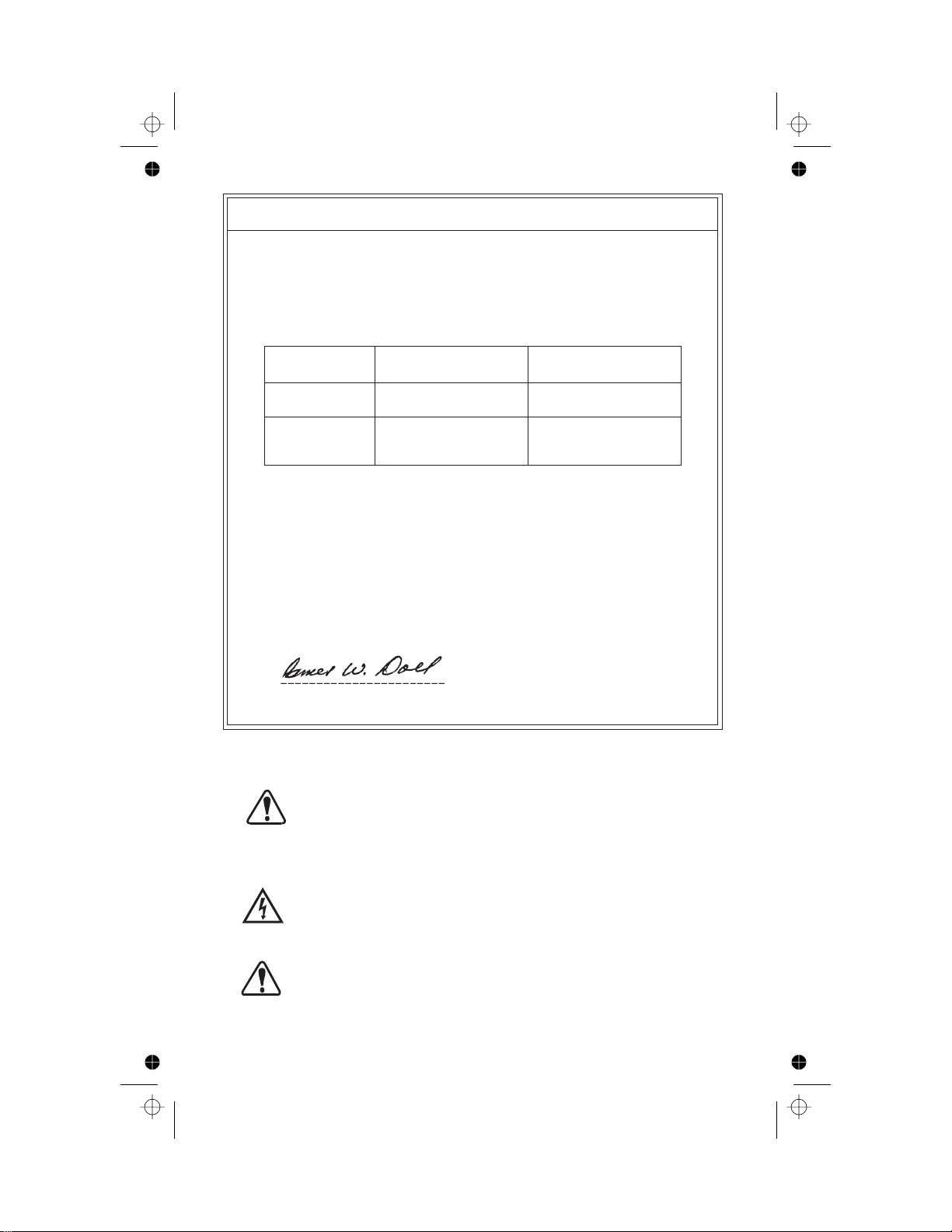
Figure 1. Typical B/T®RAPID-LOAD®Pump with LIQUI-SENSE Detector
positioned under open side of pump
–3–
ek91.chp
Tue Sep 26 14:32:43 2000
Page 6
Color profile: Disabled
Composite Default screen
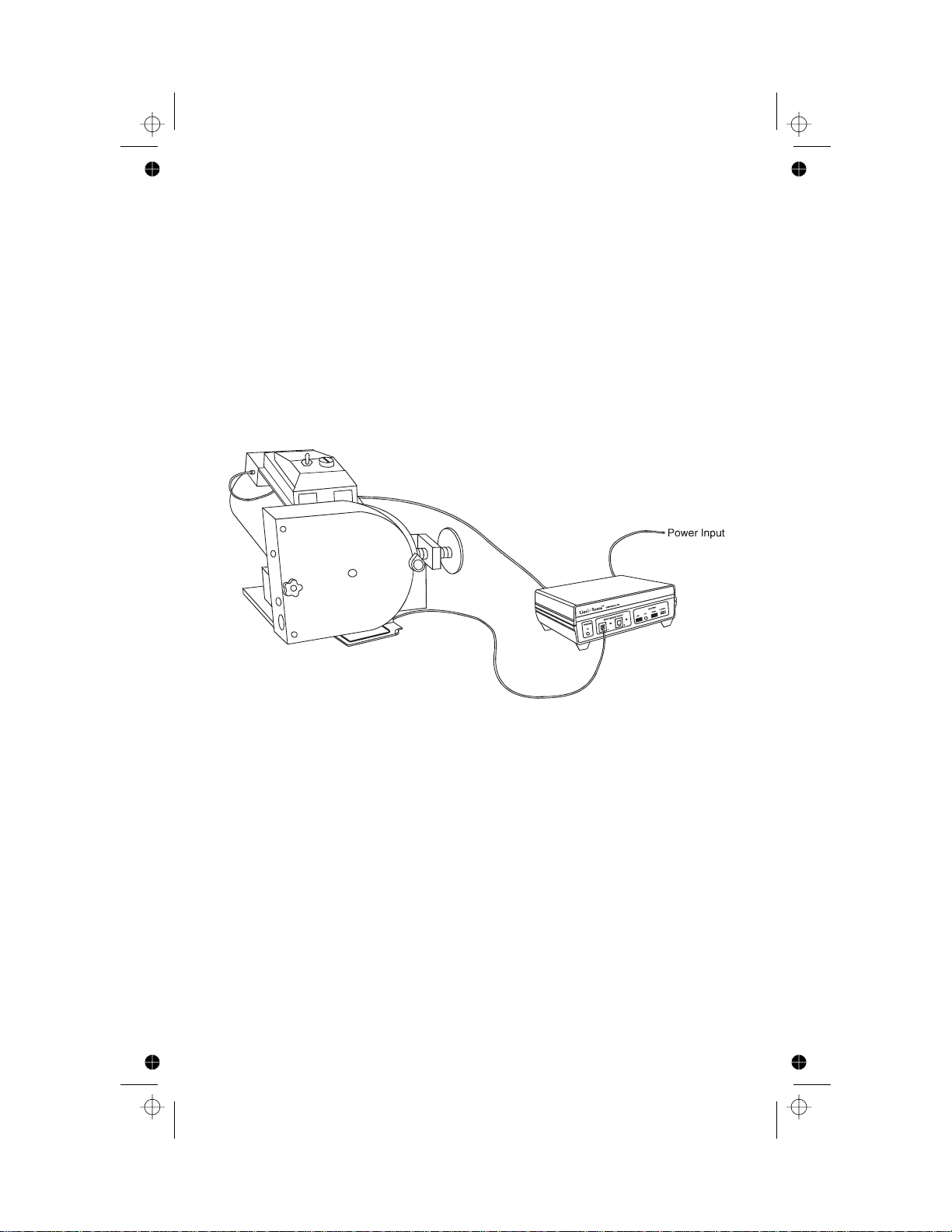
Figure 2. Typical L/S®CartridgePump with two LIQUI-SENSE Detectors
centered under the group of cartridges
Figure 3. Typical L/S EASY-LOAD®Pump with LIQUI-SENSE Detector
positioned under main pump,auxiliary pump mounted on top
of main pump and both pumps connected to Alarm Controller
for automatic swi tch over when a leak is detected
–4–
ek91.chp
Tue Sep 26 14:32:48 2000
Page 7

Color profile: Disabled
Composite Default screen
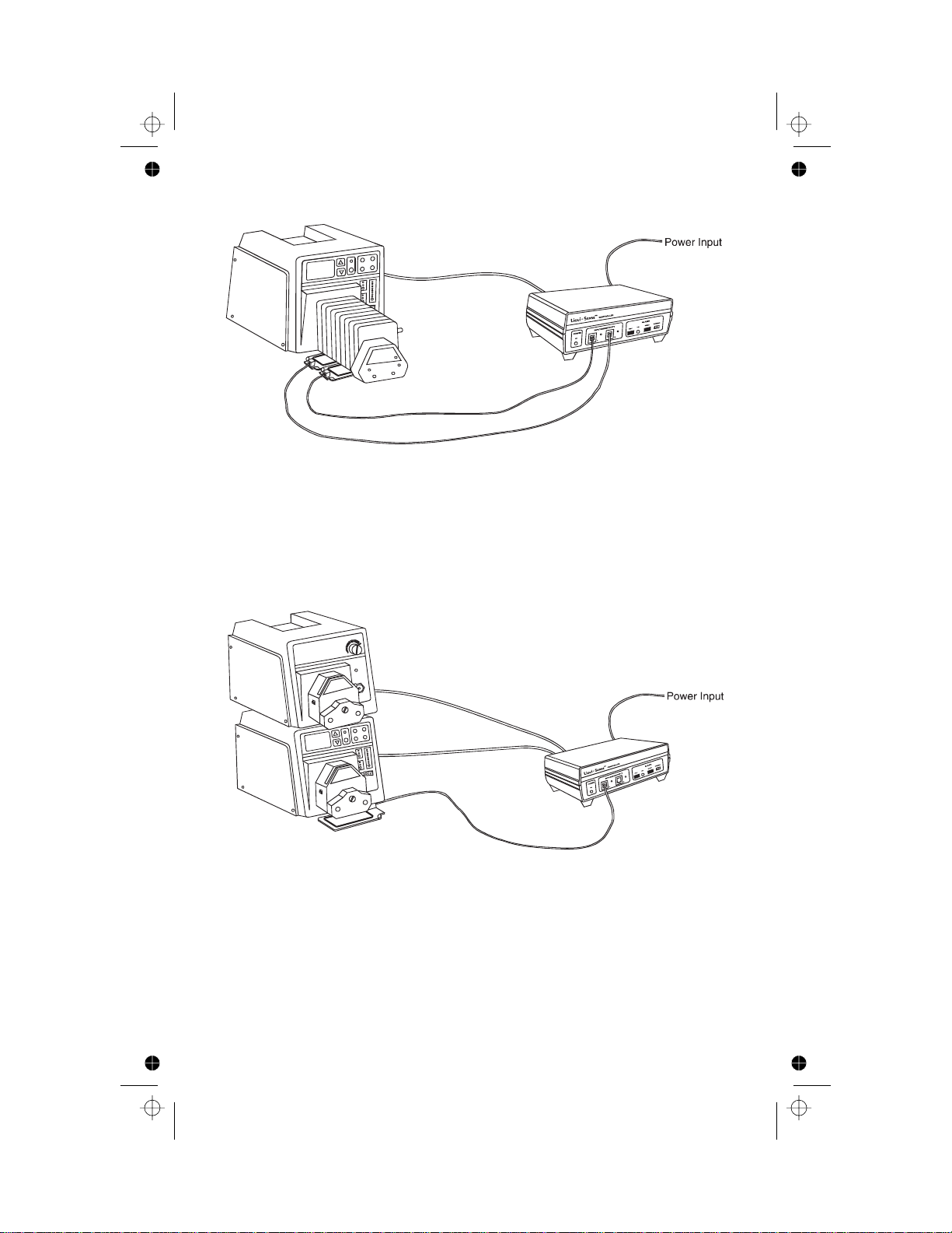
Figure 4. Typical I/P®EASY-LOAD Pump with LIQUI-SENSE Detector
centered under the pump and a level detector connected to the
second input of the Alarm Controller
Figure 5. Standard Stacked Pump System with two LIQUI-SENSE
ek91.chp
Tue Sep 26 14:32:53 2000
Detectors positioned for optimum leak detection
–5–
Page 8
Color profile: Disabled
Composite Default screen
DESCRIPTION
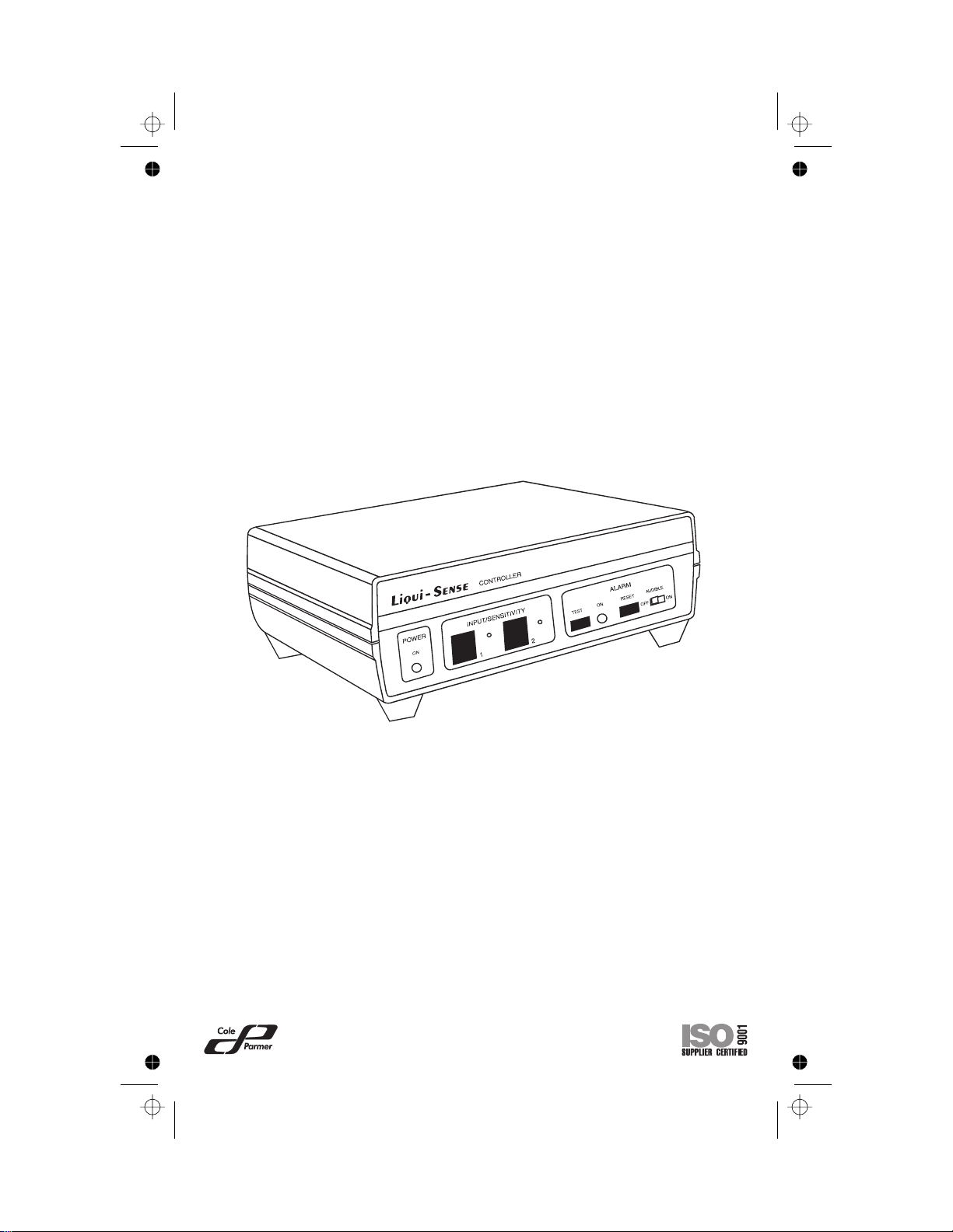
The LIQUI-SENSE Controller, shown in Figure 6, is used to monitor various
liquid detector devices. When an alarm condition is detected, the controller
deactivates the rear panel MAIN OUTPUT power connector and supplies
power to the AUXILIARY OUTPUT power connector .Also, when the alarm
condition is detected, a contact closure output is provided at the rear panel
CONTACT CLOSURE OUTPUT connector (a 1/8-inch phone-type
connector) for activating remote devices such as an Environment Monitor or
a second pump drive. The fault condition is indicated by a red ALARM ON
indicator on the front panel and by an audible alarm (unless the ALARM
AUDIBLE switchhas been set to OFF).
Figure6. LIQUI-SENSE Controller (Alarm Module)
The MAIN and AUXILIARY connectors, shown in Figures 7 and 8, are used
to connect to external devices such as pumps. The pump connected to the
MAIN OUTPUTconnector willoperate whenno alarmcondition exists.When
an alarm condition is detected, power to the MAIN OUTPUT connector is
turned off and power isapplied tothe AUXILIARY OUTPUT connector.Thus,
if nopump is connectedto the AUXILIARY OUTPUTconnector, pumpingwill
cease. If a pump is connected to the AUXILIARY OUTPUT connector, that
pump will be turned on. The switch over occurs within one second after
detection of an alarm condition.
–6–
ek91.chp
Tue Sep 26 14:32:56 2000
Page 9

Color profile: Disabled
Composite Default screen
Figure7. RearPanelModel 77096-00 (115VAC)
Figure8. RearPanelModel 77096-05 (230VAC)
Poweris applied to the unit through a permanently attached line cord on the
115V AC model and through an IEC 320/CEE 22 connector coupler (female
line cord/male socket) on the 230V AC units. A number of accessory input
and output power cords are av ai lab l e .(See ACCESSORIES.) The power is
controlled by the rear panel OFF-ON switch.Power-onis indicated by a front
panel green POWER ON indicator.
The CONTACT CLOSURE OUTPUT connector (rear panel) provides a
latched contact closure output, rated 30V DC at 1 ampere max., when an
alarm conditionis detected.This output can be connectedto an Environment
Monitor,which thencan telephonethe userto signalthe alarm condition.This
output can also be connected to any device that operates from a contact
closure condition, such as a warning system. An accessory cable is listed in
the ACCESSORIES Section.
–7–
ek91.chp
Tue Sep 26 14:33:03 2000
Page 10

Color profile: Disabled
Composite Default screen
The locking modular INPUT connectors (front panel) connect to external
detectors. Each input has a SENSITIVITY adjustment that is used only with
the LIQUI-SENSE Detectors. The sensitivity is factory set so that when the
detector is placed within one inch of the pump, less than one mL of
water-based liquid will trigger the detector. For other types of liquids, or to
change the sensitivity level, refer to the SENSITIVITY ADJUSTMENT
Section. Sensitivity adjustment may be required when operating with cables
longer than 3-1/2 feet or in a high-temperature, high-humidity environment.
TheLIQUI-SENSE Controllerishoused ina slate grayABSplastic enclosure,
with aluminumfront andrear panels.Theunit can beplaced ona flatsurface,
on asupport platformor on thetop surface ofsome MASTERFLEX
type pumps.
TheLIQUI-SENSE DetectorModel 77095-00(with cable)orModel 77095-01
(without cable), Figure 9, operates on a capacitance change principle. The
detectoris designedtobe placedunderthe pump.Ifa leakoccursin thepump
tubing, the liquid will fall on the top surface of the detector. When sufficient
surface area is moistened (less than 1 mL of water-based liquid when using
the factory sensitivity setting), the change in capacitance is sufficient to
activatethealarmcircuits.Thedetectorhas a lockingmodulartypeconnector.
The cable between the detector and the controller is 3-1/2 feet long with
modularlocking connectorson bothends.Ten-foot andfifteen-footaccessory
cablesare available.Refer toAPPENDIX Aforpinconfiguration forthecables
when connecting other detector types.
®
or other
Figure9. LIQUI-SENSE Detector Model 77095-01
A four-inch hook-and-loop fabric fastener strip allows for attachment of the
detector pad to a flat surface to prevent the detector pad from moving. The
detectorpad canalsobe permanentlymounted byattachingit to aflatsurface
with two #4 screws.The screw locations at the corners of the detector pad
are indicated by two circular markers. The detector structure will need to be
punctured by the screw for permanent attachment.
–8–
ek91.chp
Tue Sep 26 14:33:04 2000
Page 11

Color profile: Disabled
Composite Default screen
INSTALLATION AND SETUP
NOTE: Retain all packing materials until proper operationhas been verified.
WARNING:
Proceed as follows to setup the LIQUI-SENSE Controller:
1. Place the rear panel power OFF-ON switchin the OFF position.
NOTE: For 115V AC pump models, the pump power cord will plug directly
2. Connect pumps as follows:
a. If a main pump and a standby (auxiliary) pump are to be used,
TheLIQUI-SENSE Controllermustbe positioned soleaking
liquid will not enter the rear power connectors. Use of a
power line with a Ground Fault Interrupt (GFI) is recommended.
into the MAIN OUTPUT or AUXILIARYOUTPUT connectors on the
rearpanel ofthe LIQUI-SENSEController.For 230VACmodels, use
pump cable77096-50 forpumps withEuropean connectorsor pump
cable 77096-55 forpumps with other style connectors.
connect themain pumpto the MAINOUTPUT connector onthe rear
panel and connect the standby (auxiliary pump) to the AUXILIARY
OUTPUT connector.
b. If only the main pump is to be used with no standby, and the pump
is to shut down when an alarm condition exists, connect the main
pump to the MAIN OUTPUT connector. The AUXILIARY OUTPUT
connector can beused topower otherdevicessuch aslights, remote
alarms or other equipment.
c. If only the main pump is to be used with no standby, and the pump
isnot toshut downwhen analarm condition exists, connectthe main
pump to a separate power source. The MAIN OUTPUT connector
and the AUXILIARYOUTPUT connectorcan beused topower other
devices such as lights, remote alarms or other equipment.
3. Connect one end of the detector cable(s) to the front panel INPUT
connector(s) and the other end to the desired detector(s). Only one
detector canbe connectedto eachINPUT connector.Detectors mustbe
connected using a cable configured as shown in APPENDIX A. Make
surecable connectionsaresecure orunitwill notfunction pr operly.
4. The LIQUI-SENSE Detector mustbe positioned under the pump so that
anyleakage willdriponto thedetector padtarget area (areaoutlined with
the black lines). The detector can be secured in place using
hook-and-loop fabric fasteners or can be permanently fastened with #4
screws.Two circular marksare located onthe outer edgeof the detector
–9–
ek91.chp
Tue Sep 26 14:33:05 2000
Page 12

Color profile: Disabled
Composite Default screen
for position ofscrews.Do not insert screws in any other location on the
detector pads.The locationof the detector forvarious typical pumpsare
as follows:
a. Foratypical B/TRAPID-FLOW pump, the detectorshouldbe located
directly under the opening at the right side of the pump as shown in
Figure 10.
Figure10.Positioning a LIQUI-SENSEDetector
under a B/T RAPID-FLOW Pump
b. For typical L/S Cartridge pumps, the detector should be centered
under the group of cartridges. For large numbers of cartridges, use
two detectors as shown in Figure 11.
Figure11. Positioning LIQUI-SENSEDetectors
under an L/S CartridgePump
ek91.chp
Tue Sep 26 14:33:07 2000
–10–
Page 13
Color profile: Disabled
Composite Default screen
c. For typicalL/S EASY-LOAD pumps,the detector shouldbe centered
directly under the weep hole as shown in Figure 12.
Figure 12. Positioninga LIQUI-SENSE Detector under an
L/S EASY-LOAD Pump
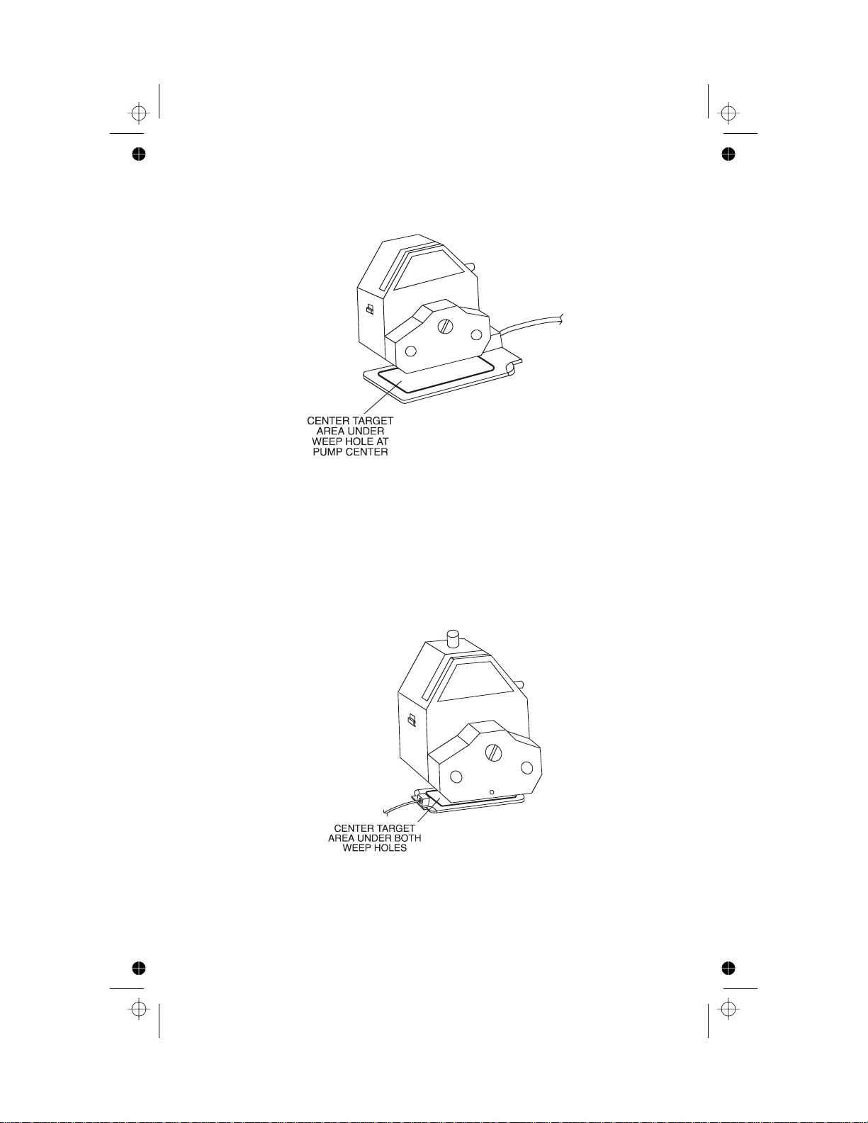
d. FortypicalI/PEASY-LOADpumps,twoweepholesare located under
the pump. A single detector can be centered under the weep holes
as shown in Figure 13. For better reliability, two separate detectors
can be used with one centered under each weep hole as shown in
Figure 14.
Figure 13. Positioning a single LIQUI-SENSE Detector under an
I/P EASY-LOAD Pump
ek91.chp
Tue Sep 26 14:33:09 2000
–11–
Page 14

Color profile: Disabled
Composite Default screen
Figure 14. Positioningtwo LIQUI-SENSE Detectors under an
e. For typical standard stacked pumps where only one or two pumps
areused,asingledetectorcanbecenteredunderthestackofpumps.
When a larger number of pumps are used, two detectors should be
positioned to assure optimumleak detection as shown in Figure15.
I/P EASY-LOAD Pump
Figure 15. Positioning two LIQUI-SENSE Detectors under a
ek91.chp
Tue Sep 26 14:33:11 2000
stack of Standard Pumps
–12–
Page 15

Color profile: Disabled
Composite Default screen
5. If an Environment Monitor (such as a COLE-PARMER Model 08330) is
to be used or if another external device requiring a contact closure to
activateitis tobeused, connectthe1/8-inch phonecableconnectorfrom
therear panelCONTACTCLOSURE OUTPUTconnector totheexternal
device.
6. Connect the LIQUI-SENSE Controller POWER INPUT cord as follows:
a. For 115V AC unit, connect line cord to 115V AC 50/60 Hz power
source.
b. For230V ACunit, connectpower cablebetween rearpanel POWER
INPUT connector and 230V AC 50/60 Hz power source.
This completes the electrical connectors. Proceed with the OPERATION
Section.
OPERATION
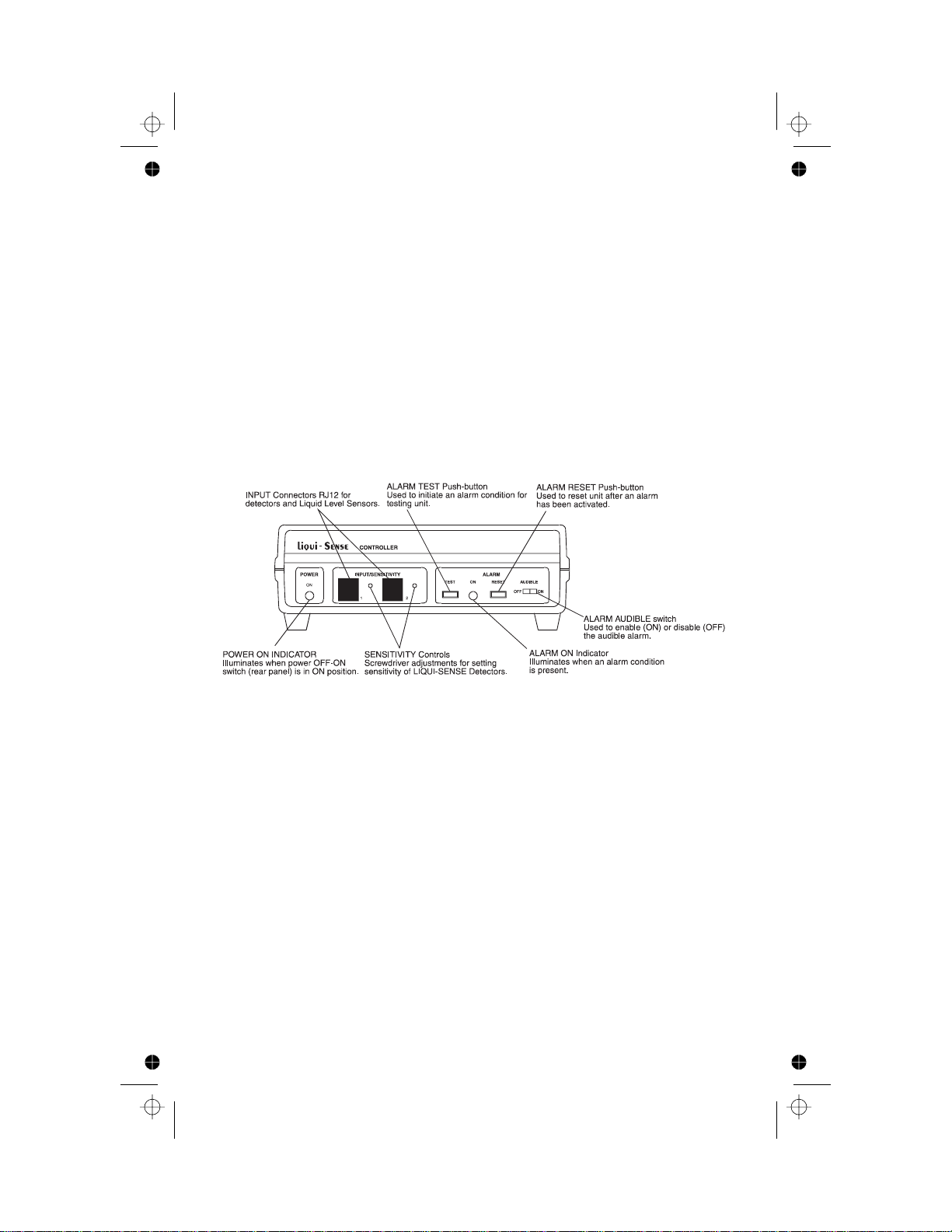
OperatorControls and Indicators
Alloperator controlsexceptthe powerOFF-ONswitchare locatedonthe front
panel as shown in Figure 16. These controls and indicatorsare as follows:
POWER ON Indicator Green LED illuminates when power
OFF-ONswitchis in theON position and
input power is present.
SENSITIVITY Controls Adjusts the sensitivity of the circuit for use
with the LIQUI-SENSE Detectors.(Pre-set
at factory for typical applications.)
ALARM TEST Momentary push-button.Tests the audible
alarm, the visual alarm, the switching of AC
power from the rear panel MAIN OUTPUT
to the AUXILIARY OUTPUT connectors and
the contact closure at the rear panel
CONTACT CLOSURE OUTPUT connector.
Theseare activated while the button is
pushed and reset automatically upon
release.
ALARM ON Indicator Red LED illuminates when an alarm
condition is present.
ek91.chp
Tue Sep 26 14:33:12 2000
–13–
Page 16

Color profile: Disabled
Composite Default screen
ALARM RESET Momentary push-button.Resets alarm
circuits afteralarm condition is removed
(detector pad wiped clean, tank filled, etc.).
Whilepush-button is held in, thesystem
reverts to the non-alarm condition.If the
alarm condition is not cleared when the
ALARM RESET switch is released, the unit
will go back into the alarm condition.It may
be convenient to hold in the ALARM
RESET button while priming or purging the
system when a leveldetector is used.
ALARM AUDIBLE
OFF-ONSwitch
In the OFF position, the audible alarm will
not sound during an alarm condition.In the
ON position, the audible alarm will sound
during an alarm condition.
PowerOFF-ON Rocker type switch located on rear panel.
Disconnects all AC powerfrom unit and
from equipment connected to the MAIN
OUTPUTor AUXILIARYOUTPUT
connectors.
Figure 16. LIQUI-SENSE Controller Front Panel
ek91.chp
Tue Sep 26 14:33:14 2000
–14–
Page 17

Color profile: Disabled
Composite Default screen
Startup Procedure
1. Check that all connections have been made as described in the
INSTALLATION Section.
2. Check that detectors are connected and properly positioned. Only one
detector can be connected to each channel. Use hook-and-loop fabric
fasteners to secure detector in position or, if permanent mounting is
desired, detector can be attached with #4 screws as described in the
INSTALLATION Section.
NOTE: Tubing may break at locations other than expected.Using a second
detector can provide for better detection.
3. If theaudible alarm isto operate, set ALARMAUDIBLE switchto theON
position. If no audible alarm is desired, place ALARM AUDIBLE switch
in the OFF position.
4. Set rear panel power OFF-ON switch to the ON position and check that
the front panel green POWER ON indicator is lit. The equipment should
now be operating normally.
5. Ifan alarmconditionexists,proceed totheSENSITIVITY ADJUSTMENT
Section. If level detectors are used, they may need to be inverted or
rotated 180° forproper operation.The audiblealarm canbe turned offby
placing the ALARM AUDIBLE s witchin the OFF position.
6. Perform the LIQUI-SENSE DetectorSensitivity Checkusing dropsof the
same liquid used in your application.
Operational Checks
LIQUI-SENSE CONTROLLER
Anoperational checkofthe LIQUI-SENSEController canbe performed using
theALARMTESTswitch.This testshouldbeperformedonlywhen temporary
transfer of power from the MAIN OUTPUT connector to the AUXILIARY
OUTPUT connector will not be disruptive.
Proceed as follows:
1. Set the ALARM AUDIBLE switch to ON for the audible alarm to be
activated or to OFF to deactivate the audible alarm.
2. Set power OFF-ON switch to ON position and check that POWER ON
indicator is illuminated.
3. Pressand holdtheALARM TESTSWITCH.Checkthatthe audiblealarm
sounds (if activated), the ALARM ON indicator isilluminated, that power
shifts from the MAIN OUTPUT connector to the AUXILIARY OUTPUT
connector and that the CONTACT CLOSURE OUTPUT activates any
equipment connected to the output.
–15–
ek91.chp
Tue Sep 26 14:33:15 2000
Page 18

Color profile: Disabled
Composite Default screen
LIQUI-SENSE DETECTOR SENSITIVITY CHECK
The LIQUI-SENSE Detector sensitivitymay be checkedas follows:
1. Connect detector to one of the front panel INPUT connectors, if not
already connected.
2. Place water one drop at a time on the detector pad. Do not drop water
from more than one inch.
3. Check numberofdrops requiredto activate alarm.Pre-setfactory setting
should activate alarm with less than 1 mL of liquid. If activation level is
not as desired, refer to SENSITIVITY ADJUSTMENT Section.
4. Afteractivatingalarm,momentarilypressthenreleasetheRESETbutton.
Alarm condition should still be present.
5. Wipe detectorsurfaceclean withadry cloth andmomentarily press,then
release, the RESET button. Alarm condition should terminate, ALARM
ON indicator should extinguish and, if activated, audible alarm should
turn off.
SENSITIVITY ADJUSTMENT
Generally, no sensitivity adjustment of the LIQUI-SENSE Controller is
required. However, various liquids or environmental conditions such as
temperature and humidity may require adjustment of the SENSITIVITY
controls for use with the LIQUI-SENSE Detectors. The SENSITIVITY
adjustment is accessed through the small hole adjacent to each INPUT
connector.Contact closure or logic level detectors do not requireadjustment
of theSENSITIVITYcontrol.
If the factory default setting for sensitivity is not activating the alarm, or is
falsely activating the alarm for the liquid being sensed, adjust the input
sensitivity with one channel connected at a time. Turn the SENSITIVITY
control clockwise to increase sensitivity (fewer drops will activate) or
counterclockwise to decrease sensitivity.
NOTE: If the sensitivity is increased so much that the red ALARM ON
indicator illuminates, the RESET button must be depressed each
time sensitivity is decreased until the indicator extingui shes.
Normal sensitivity adjustment is between one-quarter and two turns
counterclockwise from the activation point.The activation point is defined as
that sensitivity set when ALARM ON indicatorjust illuminates.Refer to Table
1fortypicalsensitivitysettings f orvarious liquids.Themiddlecolumnindicates
the number of turns counterclockwise from the activation point that the
–16–
ek91.chp
Tue Sep 26 14:33:16 2000
Page 19

Color profile: Disabled
Composite Default screen
sensitivitycontrolshouldbeset f orproper operation.Thelastcolumnindicates
the quantity of fluid required in the target area of the detector to activate the
detector.
Sensitivity will change with detector position or when used near metallic
objects (e.g., table). Also, sensitivity changes when using longer (optional)
cables.
CAUTION:
Use with caustic liquids not compatible with detector materials voids warranty.
Table 1.Typical Sensitivity Settings
Setting (Turns ccw
FluidType
Distilled Water 11⁄
Tap W at er 11⁄
Acetic Acid (10% max.) 11⁄
Alcohols 11⁄
Glycerin 11⁄
10W Motor Oil
fromactivation point) NominalVolume
2
2
2
2
2
1
⁄
2
<1mL
<1mL
<0.5mL
<0.5mL
<2.0mL
<2.0mL
MAINTENANCE ANDTROUBLESHOOTING
WARNING:
Fuse Replacement
The 115V AC LIQUI-SENSE Controller uses a 10-A Slo-Blo fuse (3AG, part
number B-1115-0052), which is located in the fuse holder on the rear panel.
The 230V AC LIQUI-SENSE Controller uses a 6.3-A fuse (5 x 20 mm, part
number B-1115-0054), which is located inthe drawer in the POWER INPUT
connector on the rear panel.Replace only with the correct fuse.
Cleaning
Clean the topsurfaceof thedetector padwith asoft, dry cloth.If liquidcleaner
is used, rinse and dry thoroughly before resuming operation. Keep the
LIQUI-SENSE Controller enclosure clean by using a mild detergent. Never
immerse or use excess fluid.
Nouserserviceable partsareinside of thisController.Refer
servicing to your dealer.
–17–
ek91.chp
Tue Sep 26 14:33:17 2000
Page 20

Color profile: Disabled
Composite Default screen
Troubleshooting
The following chart will help identify most problems that can be corrected by
the operator.If the faultcannot be located, return unit for servicing.
Troubleshooting Chart
SYMPTOM CAUSE REMEDY
POWERON indicator
does not illuminate
with PowerOFF-ON
switch in ON position
ALARM LIGHT
illuminates but
audible alarm does
not sound
Alarm does not
activate for a fault
condition
RESET button does
not reset unit when
depressed
Alarm activated but
pump continues to
operate
Alarm activated but
auxiliary pump does
not turn on
Fuse blown Replace fuse
Powercord not
Plug in power cord
plugged into active
power source
ALARM AUDIBLE
switch not set to ON
Set switch toON
position
position
Detector not connected Connect detector
Sensitivity set too low Increase sensitivity
(LIQUI-SENSE
Detector only)
Detector cable
Replace cable
defective
Detector inoperative Replace detector
Faultnot cleared Clear fault
Sensitivity settoo
high
Lower sensitivity
(LIQUI-SENSE
Detector only)
RESET button failure Return unit forservicing
Pump not connected
to MAINOUTPUT
but directly to a
power source
Auxiliary Pump not
connected to
AUXILIARY OUTPUT
Connect pump to MAIN
OUTPUTfor shutdown
when an alarm
condition is sensed.
Connect auxiliary pump
to AUXILIARY
OUTPUT
ek91.chp
Tue Sep 26 14:33:17 2000
–18–
Page 21

Color profile: Disabled
Composite Default screen
ACCESSORIES
Theaccessories andservice parts listedbelowareavailablefromyourdealer.
Part Name Part Number
LIQUI-SENSE Detector Pad and 3.5 ft Cable 77095-00
LIQUI-SENSE Detector Pad 77095-01
Cable, Detector Pad, 3.5 ft 77095-02
Cable, Detector Pad, 10 ft 77095-03
Cable, Detector Pad, 15 ft 77095-04
IEC320M/IEC320F Pump power
cable (connects modular plug
to LIQUI-SENSE Controller) 77096-50
IEC320F/F Pump power cable
(connects European plug
to LIQUI-SENSE Controller) 77096-55
Cable with 1/8-inch phone plug 23000-70
Out-of-Liquid Detector 77095-50
PowerCords for 230V AC Controllers
European (standard) 50001-70
British 50001-72
Swiss 50001-74
Italian 50001-76
NEMA Type 6-15P 50001-78
Fuse
115V: 10A, 250V, SLO-BLO, 3AG B-1115-0052
230V: T6.3A, 250V, 5220mm B-1115-0054
ek91.chp
Tue Sep 26 14:33:18 2000
–19–
Page 22

Color profile: Disabled
Composite Default screen
SPECIFICATIONS
Output:
Contact Closure Output Rating: 30V DC—1 Ampere Maximum
AudibleAlarm Sound Level: 90 dBA
Input:
Line Voltage Limits
(115V AC Controller): 102–132V AC 50/60 Hz Single Phase*
(230V AC Controller): 190–260V AC 50/60 Hz Single Phase
PowerDissipation: 1.2 kVA maximum
AC Line Current: 10 A max at 115V A C
6.3 A max at 230V AC
Installation Category: Installation Category II per IEC 664
(Local level —appliances,portable
equipment, etc.)
Construction:
Controller Dimensions: 3 in H 2 8.1in W 2 6.3 in D
LIQUI-SENSE
Detector Dimensions: 5.0 in 2 2.6 in
Weight: 3 lbs
Detector Cable Length: 3.5 feet (others av ai lab l e)
Enclosure Rating: IP22 per IEC 529
Environment:
Operating Temperature Range: 0°C(32°F) to 40°C (104°F)
Storage Temperature: −45°C(−49°F) to 65°C (149°F)
Humidity (non-condensing): 10 to 85%
Barometric Pressure: 75 to 106 kPa
Altitude: less than 2000 m
PollutionDegree: Pollution Degree 2 per IEC 664
(Indoor Usage—lab, office)
Chemical Resistance:
LIQUI-SENSE Controller: All materials withstand common
cleaning solvents.Construction
materials used are polyester
labels, ABS plastic enclosure and
zinc-plated screws.
LIQUI-SENSE Detector: Top layer — Flat polyester attached
with polyester laminate.
Bottom layer — Polyester attached
with polyester laminate.
Connector is ABS plastic.
Compliance: 115V:UL508, CSA C22.2, No.14-M91
230V (For CE Mark):
EN61010-1/A2: 1995
(EU Low Voltage Directive) and
EN61326-1/A1: 1998 (EU EMC Directive)
Unitoperating voltage rangeas tested byUnderwritersLaboratories.This unit hasbeen designedand testedby the
*
manufacturer foran extendedoperatingvoltage rangeof 90–132VAC.
ek91.chp
Tue Sep 26 14:33:19 2000
–20–
Page 23

Color profile: Disabled
Composite Default screen
W ARRANTY
The Manufacturerwarrants this product to be freefrom significant deviations
from published specifications.If repair or adjustment is necessary within the
warranty period, the problem will be corrected at no charge if it is not due to
misuse or abuse on your part, as determined by the Manufacturer. Repair
costs outside the warranty period, or those resulting from product misuse or
abuse, maybe invoiced to you.
The warranty period for this product is noted on the Warranty Card.
PRODUCT RETURN
To limit charges and delays, contact the seller or Manufacturer for
authorization and shipping instructions before returning the product, either
within or outside of the warranty period. When returning the product, please
state thereason for thereturn. For your protection, packthe productcarefully
and insure it against possible damage or loss. Any damages resulting from
improper packaging are your responsibility.
TECHNICAL ASSISTANCE
If you have any questions about the use of this product, contact the
Manufacturer or authorized seller.
We reserve the right to make improvements in design, construction and
appearance of our products without notice.
ek91.chp
Tue Sep 26 14:33:20 2000
–21–
Page 24

Color profile: Disabled
Composite Default screen
APPENDIX A
AUXILIARY CABLE CONNECTIONS
Each Cable Assembly is 3-1/2 feet long and is composed of a 6-conductor
shielded flat cable with PVC jacket. Ten-foot and fifteen-foot cables are also
available. Six pin modular plugs are attached at each end. Refer to the
following chart for pin output:
Pin Signal Color
1Ground Black
2 Contact Closure or Logic Low
Input
3 12V DC Red
4 Capacitive Plate Input Green
5 Capacitive Plate Input Brown
6 Shield Guard BareTin
White
For level detector (sensors) connections,cut off one endof the sixconductor
flat cable, or cut the cable in half, if using longer cables, to make two pieces.
Strip the shield (metal) and plastic jacket back two inches.Spread the wires.
Strip back one inch of the black wire, pin 1, and white wire, pin 2. Fold the
other wires back along the plastic jacket and tape or cut off as desired.Twist
one lead of the level detector to t he black lead of the cable, pin 1, and twist
the otherlead of theleveldetector to thewhite lead ofthe cable,pin 2.Solder
the two connections together or use a wire nut if possible. Tape around
exposed bare wire areas.
FigureA-1. Level Sensor Connections
Printed in U.S.A.
030800
–22–
ek91.chp
Tue Sep 26 14:33:21 2000
 Loading...