

Page 1
®
®
OPERATING MANUAL:
PUMP DRIVES
NOTICE D’UTILISATION :
ENTRAÎNEMENTS DE
POMPE
BEDIENUNGSANLEITUNG:
PUMPENANTRIEBE
MANUAL DE OPERACIÓN:
PROPULSORES DE LA
BOMBA
MANUALE DI ISTRUZIONI:
AZIONAMENTI
Model Nos.
Modèle nº
Modellenummern
Número de modelo
Modello nº
7591-07
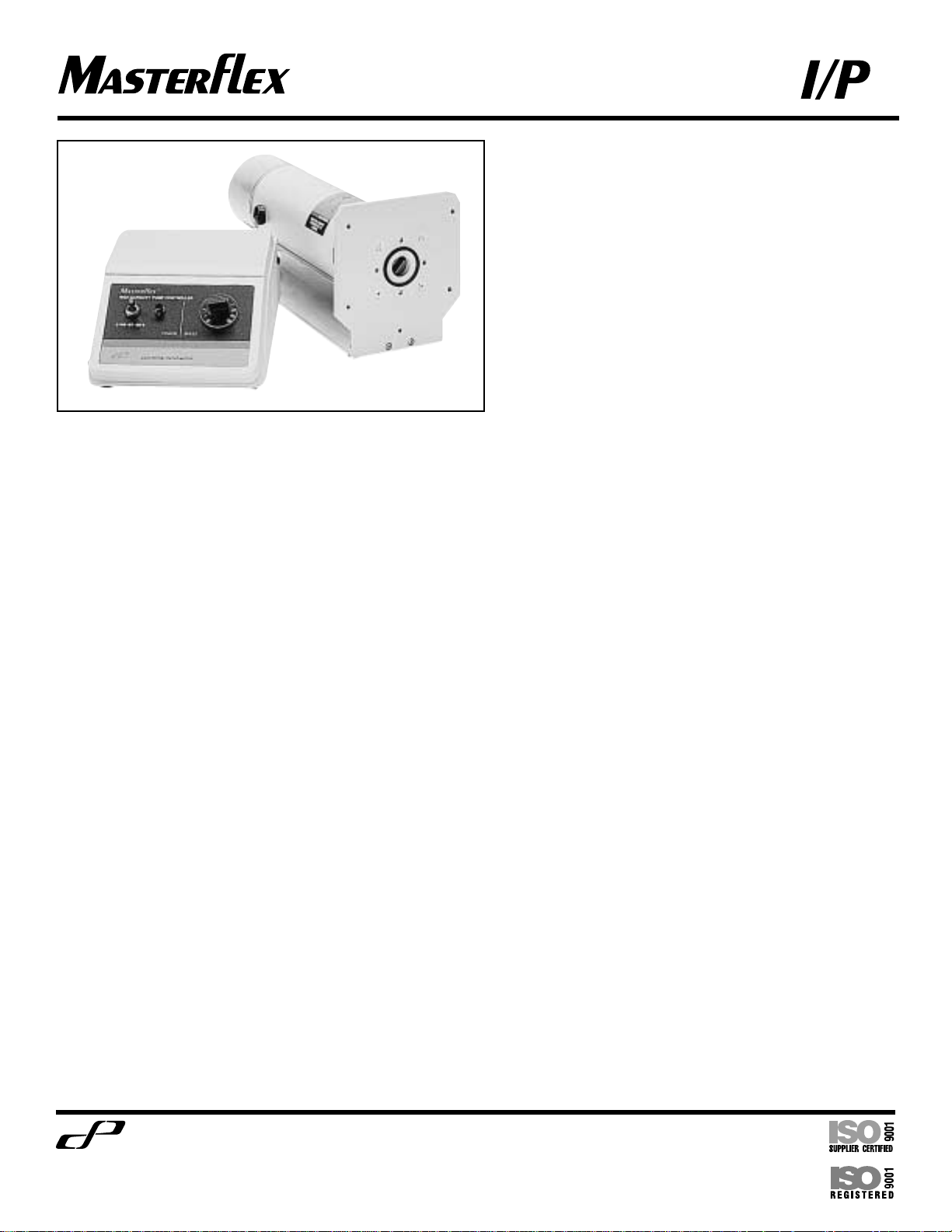
07591-07 Benchtop Pump Controller Drive System
Cole
Parmer
®
Cole-Parmer Instrument Co.
"
1-800-MASTERFLEX (627-8373) (U.S. and Canada only)
"
11 (847) 549-7600 (Outside U.S.)"(847) 549-7600 (Local)"www.masterflex.com
Barnant Company
"
1-800-637-3739 (U.S. and Canada only)
"
11 (847) 381-7050 (Outside U.S.)"(847) 381-7050 (Local)"www.barnant.com
A-1299-0694
Edition 03
Page 2
®
®
®
Cole-Parmer Instrument Company
HIGH CAPACITY PUMP CONTROLLER
SAFETY PRECAUTIONS
DANGER: High voltages exist and are accessible
in the Drive/Controller.
WARNING: Disconnect the AC power input line
cord before connecting the drive motor
cable.
WARNING: No user serviceable parts are inside
of this controller. Refer servicing to your
dealer.
WARNING: PRODUCT USE
LIMITATION
This product is not designed for, nor intended for
use in patient connected applications; including,
but not limited to medical and dental use and
accordingly, has not been submitted for FDA
approval.
Variety of Pump Heads
Accepted
Mount up to 2 MASTERFLEX®I/P®pump heads
and all MASTERFLEX–compatible pump heads.
Setup and Drive Operation
1. Mount pump head and load tubing.
(See pump head manual.)
2. Connect the drive motor cable to the receptacle
on the rear side of the controller.
3. Connect the AC power input line cord to the AC
receptacle.
4. Selecting motor direction turns pump on.
5. Adjust flow rate with speed control
potentiometer.
MESURES DE SÉCURITÉ
DANGER: Des hautes tensions existent et sont
présentes dans le moteur/contrôleur.
AVERTISSEMENT: Débranchez la ligne
d’alimentation alternative avant de
brancher le câble du moteur
d’entraînement.
AVERTISSEMENT: Il n’y a pas de pièce
réparable par l’utilisateur à l’intérieur
de ce contrôleur. Demandez à votre concessionnaire d’effectuer les réparations.
AVERTISSEMENT : LIMITES
D’UTILISATION DU PRODUIT
Ce produit n’est pas conçu ni supposé être utilisé
dans les applications relatives à des patients; y
compris, mais sans s’y limiter, l’utilisation médicale ou dentaire, et par conséquent n’a pas été
soumis à l’accord de la FDA.
Variété de têtes de pompe
acceptées
Supporte 2 têtes de pompe I/P®MASTERFLEX®et
toutes les têtes de pompe compatibles
MASTERFLEX.
Configuration et fonctionnement de l’entraînement
1. Monter la tête de la pompe et charger le tube.
(Voir le manuel de tête de pompe.)
2. Brancher le câble du moteur d’entraînement à la
prise à l’arrière du contrôleur.
3. Brancher le cordon d’alimentation en courant
alternatif sur la prise de courant alternatif.
4. Sélectionner la direction du moteur permettant la
mise en route de la pompe.
5. Régler le débit d’écoulement avec le
potentiomètre de commande de vitesse.
SICHERHEITSMASSNAHMEN
GEFAHR: Im Antrieb herrscht Hochspannung,
die unter Umständen zugänglich ist.
WARNUNG: Vor Anschluß des
Verbindungskabels Motor/Controller
Netzstecker ziehen.
WARNUNG: Enthält keine Teile, die selbst
repariert werden können. Bitte wenden
Sie sich wegen Wartungen und
Reparaturen an Ihren Fachhändler.
ACHTUNG! ANWENDUNGSEINSCHRÄNKUNGEN
Dieses Gerät ist nicht für Einsätze am Patienten
vorgesehen und auch nicht für diesen Zweck
bestimmt (z. B. im medizinischen oder
zahnmedizinischen Bereich) und entspricht
demgemäß auch keinen FDA (Food & Drug
Administration) Normen.
Auswahlmöglichkeiten der
Pumpenköpfe
Bis zu 2 MASTERFLEX®I/P®Pumpenköpfe sowie
alle MASTERFLEX-kompatiblen Pumpenköpfe.
Montage und Betrieb
1. Pumpenkopf montieren und Schlauch einlegen.
(Siehe Bedienungsanleitung für Pumpenköpfe.)
2. Verbindungskabel an der Rückseite des
Controllers anschließen.
3. Netzstecker an Steckdose anschließen.
4. Durch Wahl der Drehrichtung wird die Pumpe
eingeschaltet.
5. Drehzahlregelung über Potentiometer.
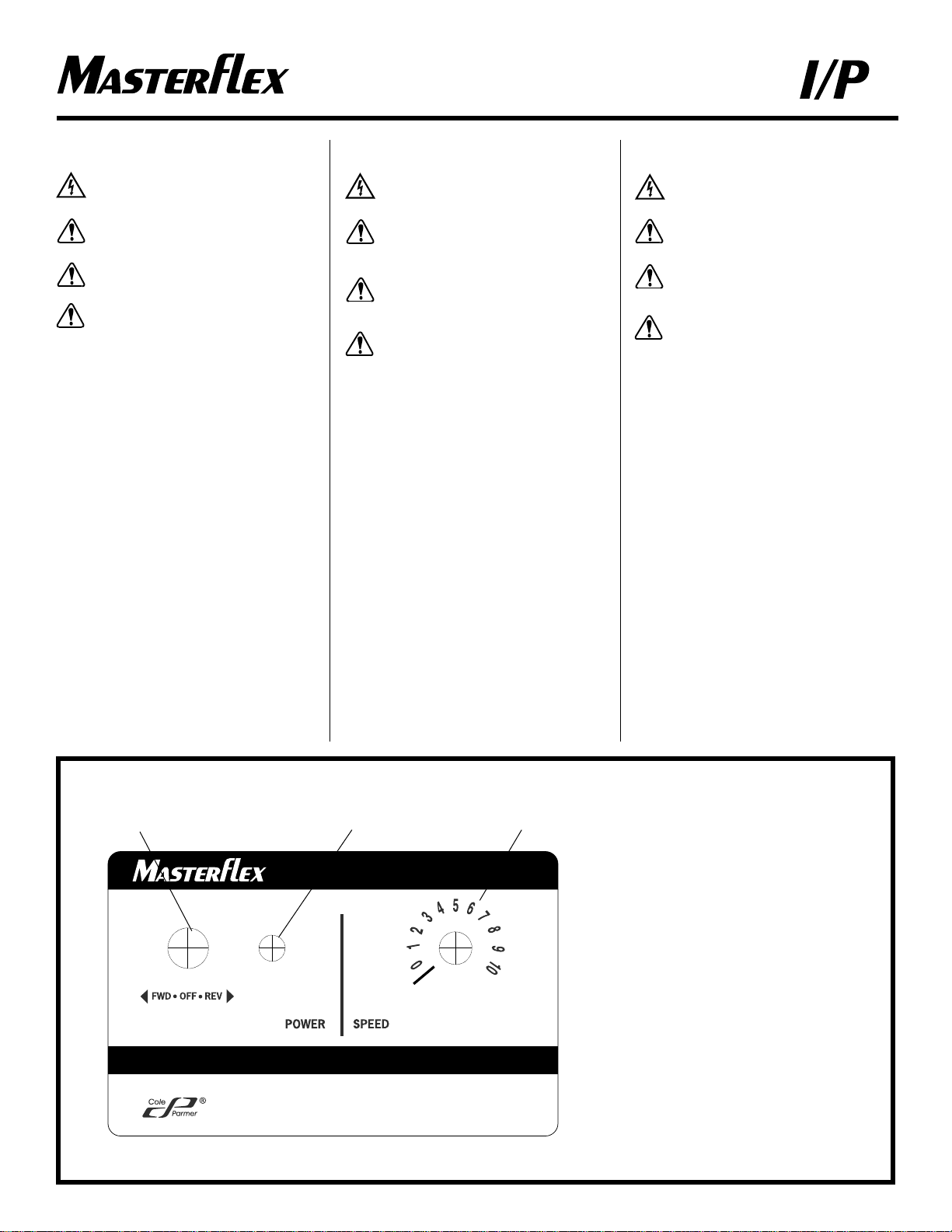
FRONT VIEW OF CONTROLLER
VUE AVANT DU CONTROLEUR
VORDERANSICHT
VISTA FRONTAL DEL CONTROLADOR
VISTA FRONTALE DEL CONTROLLORE
A) Forward-Off-Reverse Switch
Commutateur Marche
Avant-Arrêt-Marche Arriere
Vorwärts/Aus/Rückwärts-Schalter
Interruptor de Hacia Adelante-
Apagar-Hacia Atrás
Selettore Avanti/Spento/Indietro
B) Power On Indicator
Temoin de Marche
Betriebsanzeige
Indicador de Energía
Spia Alimentazione
C) Speed Control
Commande de Vitesse
Drehzahlregelung
Control de Velocidad
Controllo di velocita'
A
BC
2
Trademarks bearing the ®symbol in this publication
are registered in the U.S. and in other countries.
Page 3
®
®
PRECAUCIONES DE SEGURIDAD
PELIGRO: Existe alto voltaje y está al alcance
en el Propulsor/Controlador.
ADVERTENCIA: Desconecte el cable de entrada
de energía AC antes de conectar el cable
del motor del propulsor.
ADVERTENCIA: Dentro del Propulsor no hay
partes que puedan ser reemplázadas por
el usuario. Remítalo a su distribuidor
para obtener servicio.
ADVERTENCIA: LIMITACIÓN
DE USO DEL PRODUCTO
Este producto no está diseñado ni destinado para
ser usado en aplicaciones conectadas en
pacientes, incluyendo, pero no limitado a uso
médico y dental, y por lo tanto no ha sido
sometido a la aprobación del FDA.
Variedad de las Cabezas de la
Bomba Aceptadas
Instale hasta 2 cabezas de bomba MASTERFLEX
®
I/P®y todas las cabezas de bomba compatibles con
MASTERFLEX.
Montaje y Operación del
Propulsor
1. Instale la cabeza de la bomba y monte la tubería.
(Vea el manual de la cabeza de la bomba.)
2. Conecte el cable del motor del propulsor en el
tomacorriente en la parte posterior del controlador.
3. Conecte el cable de entrada de energía AC en el
tomacorriente AC.
4. Seleccionando la dirección del motor enciende la
bomba.
5. Fije la rata de flujo con el control de velocidad
del potenciómetro.
PRECAUZIONI RIGUARDANTI
LA SICUREZZA
PERICOLO: Nell’azionamento sono accessibili
componenti ad alto voltaggio.
ATTENZIONE: Staccare il cavo di
alimentazione CA prima di collegare il
cavo del motore.
ATTENZIONE: Per la manutenzione rivolgersi
esclusivamente al Distributore.
AVVERTENZA: LIMITI
D’USO DEL PRODOTTO
Il prodotto non ha l’approvazione FDA per uso
medico e dentistico. Non usare direttamente su
pazienti.
Compatibilita’ con teste
pompanti
Possibilita’ di installare fino a 2 teste pompanti
MASTERFLEX®I/P®e tutte le teste pompanti
compatibili con le MASTERFLEX.
Avvio e funzionamento
1. Installare la testa pompante ed inserire il tubo.
(Cfr. il manuale della testa pompante.)
2. Collegare il cavo del motore alla presa sul lato
posteriore del controllo.
3. Inserire il cavo di alimentazione CA nell’apposito
spazio.
4. Scegliere la direzione del motore ed avviare la
pompa.
5. Regolare la portata tramite il potenziometro del
controllo di velocita’.
SETUP AND DRIVE
OPERATION
CONFIGURATION ET
FONCTIONNEMENT
DE L'ENTRAINEMENT
MONTAGE UND BETRIEB
MONTAJE Y OPERACION DEL
PROPULSOR
AVVIO E FUNZIONAMENTO
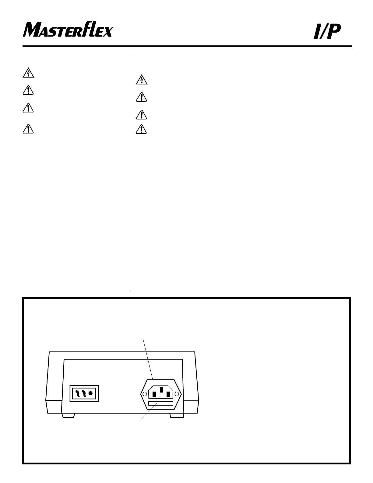
REAR VIEW OF CONTROLLER
VUE ARRIERE DU CONTROLEUR
RÜCKANSICHT
VISTA POSTERIOR DEL CONTROLADOR
VISTA POSTERIORE DEL CONTROLLORE
A) IEC 320 Power Entry Module
Module Entree Alimentation IEC 320
Sicherung (austauschbar) IEC 320
Modulo de Entrada de Energía IEC 320
Presa di alimentazione IEC 320
B) Replaceable fuse (230V) T2.5A, 250V
Fusible Rempalçable (230V) T2,5A, 250V
Eingang für Netzanschluß (230V) T2,5A, 250V
Fusible Reemplazable (230V) T2,5A, 250V
Alloggiamento Fusibile (230V) T2,5A, 250V
B
3
A
Page 4
®
®
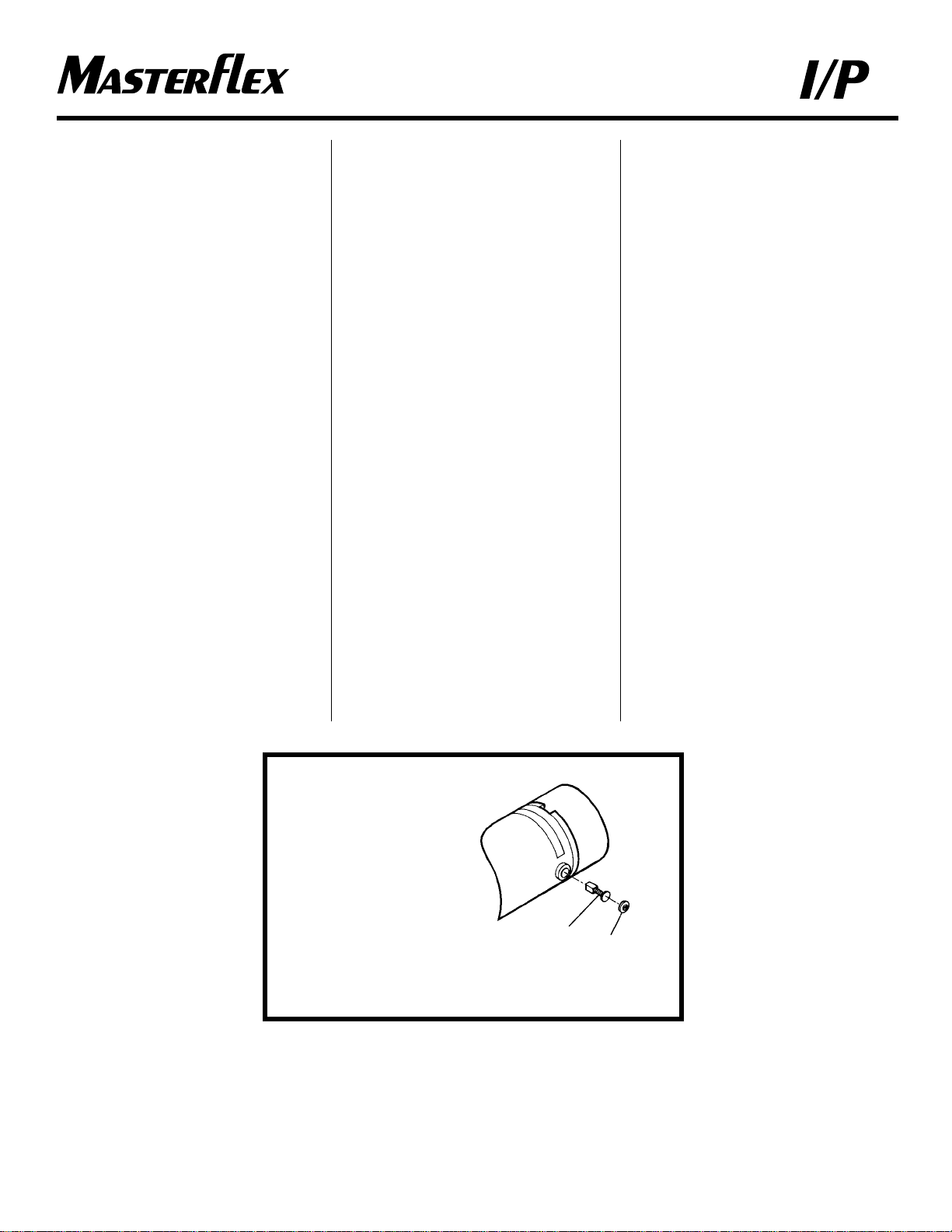
A) Motor Brush
Balai
Kohlebürste
Escobilla del motor
Spazzola motore
B) Cap
Capuchon
Abdeckkappe
Tapa
Cappuccio
MOTOR BRUSH
CHECK/REPLACEMENT
Note: Brushes should be checked every 6 months or
3000 operating hours.
1. Place the FWD-OFF-REV switch in the OFF
position.
2. Disconnect the AC line cord from the AC
receptacle.
3. Disconnect the drive motor cable from the
receptacle on the rear of the controller.
4. Carefully unscrew each brush holder on opposite
sides of the motor. Withdraw the brush, and
examine it for wear.
Note: Replace both brushes, if either brush is less
than 0.375 in long from base to point.
5. Screw brushes into brush holder on each side of
motor.
6. Connect motor to rear panel connector on
controller.
7. Connect AC line cord to AC receptacle.
Fuse Replacement
1. On 230V units, place the FWD-OFF-REV switch
in the OFF position.
2. Disconnect the AC line cord from the rear of the
unit.
3. Remove and check the fuse located on the rear
panel below the AC power connector and replace
if defective.
4. Reconnect AC line cord.
INSPECTION ET REMPLACEMENT
DES BALAIS DU MOTEUR
Remarque: Les balais doivent être inspectés tous les
6 mois ou toutes les 3000 heures de fonctionnement.
1. Placer le commutateur M. Av - Arrêt - M. Arr en
position Arrêt.
2. Débrancher le cordon d’alimentation alternative de
la prise de courant alternatif.
3. Débrancher le câble du moteur d’entraînement de
la prise à l’arrière du contrôleur.
4. Dévisser soigneusement chaque porte-balai sur les
côtés opposés du moteur. Retirer le balai et
examiner son usure.
Remarque: Remplacer les deux balais si l’un d’eux a
une longueur inférieure à 9,5 mm de la base à la
pointe.
5. Visser les balais sur les porte-balai de chaque côté
du moteur.
6. Brancher le moteur sur le connecteur du panneau
arrière du contrôleur.
7. Brancher le cordon d’alimentation alternative sur la
prise de courant alternatif.
Remplacement du fusible
1. Sur les unités de 230V, metter le commutateur
M.Av - Arrêt- M. Ar en position Arrêt.
2. Débrancher le cordon d’alimentation alternative de
l’arrière de l’unité.
3. Déposer et vérifier le fusible sur le panneau arrière
sous le connecteur d’alimentation en courant
alternatif et remplacer-le s’il est défectueux.
4. Rebrancher le cordon d’alimentation en courant
alternatif.
ÜBERPRÜFUNG UND
AUSWECHSELN DER
KOHLEBÜRSTEN
Hinweis: Die Bürsten sollten alle 6 Monate oder
3,000 Betriebsstunden geprüft werden.
1. Den Vorwärts/OFF/Rückwärts-Schalter in die
OFF Position stellen.
2. Netzstecker ziehen.
3. Verbindungskabel Motor/Controller an der
Rückseite des Steuergerätes ziehen.
4. Vorsichtig die beiden Abdeckkappen der Bürsten
abschrauben. Bürsten herausnehmen und auf
Abnutzungserscheinungen prüfen.
Bemerkung: Beide Kohlebürsten ersetzen, wenn
einer der beiden weniger als 9,5 mm lang ist.
5. Die Kohlebürsten in die jeweiligen Halter auf
jeder Motorseite schrauben.
6. Verbindungskabel Motor/Controller anschließen.
7. Netzstecker anschließen.
Auswechseln der Sicherungen
1. Bei den 230 V Modellen den Vorwärts/OFF/
Rückwärts-Schalter auf OFF stellen.
2. Netzstecker ziehen.
3. Sicherung auf der Gehäuserückseite unterhalb
des Netzsteckers ausbauen und prüfen, ggf.
auswechseln.
4. Netzstecker anschließen.
4
(A)
MOTOR
BRUSH
(B)
CAP
Page 5
®
®
MOTOR BRUSH
CHECK/REPLACEMENT;
REPLACEMENT PARTS
INSPECTION ET REMPLACEMENT
DES BALAIS DU MOTEUR ;
ACCESSOIRES ET PIÈCES DE
RECHANGE
ÜBERPRÜFUNG UND
AUSWECHSELN DER
KOHLEBÜRSTEN;
ERSATZTEILE
REVISIÓN DE LAS ESCOBILLAS
DEL MOTOR Y REEMPLAZO;
PIEZAS DE REEMPLAZO
CONTROLLO/SOSTITUZIONE
SPAZZOLE MOTORE;
PARTI DI RICAMBIO
REVISIÓN DE LAS ESCOBILLAS
DEL MOTOR Y REEMPLAZO
NOTA: Las escobillas deberán ser revisadas cada
6 meses o cada 3000 horas de operación.
1. Coloque el interruptor de FWD-OFF-REV en la
posición de apagado, “OFF”.
2. Desconecte el cable de entrada de energía AC del
tomacorriente AC.
3. Desconecte el cable del motor del propulsor del
tomacorriente en la parte posterior del controlador.
4. Cuidadosamente desatornille cada soporte de las
escobillas a los lados opuestos del motor. Retire
las escobillas y examínelas para ver si están
desgastadas.
NOTA: Reemplace ambas escobillas, si la longitud
de cualquiera de las dos es menor de
9,5 mm de la base a la punta.
5. Atornille las escobillas en los soportes a cada
lado del motor.
6. Conecte el motor al conector del panel posterior
del controlador.
7. Conecte el cable de entrada de energía AC en el
tomacorriente AC.
Reemplazo de los fusibles
1. En las unidades de 230 V, coloque el interruptor
FWD-OFF-REV en la posición de apagado, “OFF”.
2. Desconecte el cable de energía AC de la parte
posterior de la unidad.
3. Saque y revise los fusibles ubicados debajo del
conector de energía AC en el panel posterior y
reemplácelos si están defectuosos.
4. Reconecte el cable de energía AC.
CONTROLLO/SOSTITUZIONE
SPAZZOLE MOTORE
NOTA: le spazzole devono essere controllate
ogni sei mesi oppure ogni 3000 h di
funzionamento.
1. Porre l’interruttore FWD-OFF-REV in posizione
OFF.
2. Staccare il cavo di alimentazione.
3. Staccare il cavo del motore dal controllo.
4. Staccare con cura il sufforto delle spazzole dai
lati opposti del motore. Togliere le spazzole per
verificarne le condizioni.
NOTA: se entrambe le spazzole misurano meno di
9,5 mm da un capo all’altro è necessario
sostituirle.
5. Rimettere le spazzole nel contenitore avvitandolo
al motore.
6. Collegare il motore al pannello posteriore del
controllo.
7. Collegare il cavo di alimentazione CA.
Sostituzione dei fusibili
1. Sulle unità da 230 V mettere l’interruttore
FWD-OFF-REV in posizione OFF.
2. Staccare il cavo di alimentazione dal retro
dell’apparecchio.
3. Togliere e controllare il fusibile situato sotto
il pannello posteriore dietro il punto di
collegamento dell’alimentazione e sostituirlo
se difettoso.
4. Ricollegare il cavo di alimentazione CA.
REPLACEMENT PARTS • ACCESSOIRES ET PIÈCES DE RECHANGE
ERSATZTEILE • PIEZAS DE REEMPLAZO
PARTI DI RICAMBIO
Model No./Modèle nº
Modell-Nr./Número de modelo 7591-07
Modello nº
Brushes (2/set)/Balais (2/jeu)
Kohlebürsten (2/St.)/Escobillas (2 juegos) 07520-04
Spazzole (set da 2)
Brush Cap Holder/Support de capuchon de balai
Halterung für Abdeckkappen/Soporte de la tapa de la escobilla 07520-03
Contenitore tappi spazzole
Fuses (T2.5A, 250V)/Fusible (T2,5 A, 250 V)
Sicherungen (T2,5 A, 250 V)/Fusibles (T2,5 A, 250 V) 77500-08
Fusibili (T2,5 A, 250 V)
Motor only/Moteur uniquement
Motor einzeln/Motor de repuesto/Motore 07591-55
Controller only/Contrôleur uniquement
Controller einzeln/Controlador de repuesto/Controllore 07591-67
Rubber Caps & Brushes Kit/Capuchons de protection et jeu de balais
Kit mit Gummikappen und Bürsten/Tapas de goma y juego de 07553-03
cepillos/Kit di spazzole e tappi in gomma
5
Page 6

®
®
A. Defective line cord or fuse.
Cordon ou fusible défectueux.
Netzkabel oder Sicherung defekt.
Cable de energía o fusible defectuoso.
Cavo o fusibile difettoso.
B. Defective Motor or Controller.
Moteur ou contrôleur défectueux.
Motor oder Controller defekt.
Motor o controlador defectuoso.
Motore o controllore difettoso.
Troubleshooting • Dépannage • Mögliche Funktionsstörungen • Localización de averías • Problemi
Symptom/Symptome/ Cause/Cause/ Remedy/Solution/
Stôrung/Sintoma/ Grund/Causa/ Vorgehensweise/Solucion/
Sintomi Causa Rimedio
A. Motor does not rotate, when switched to
FWD or REV. POWER indicator does not
glow.
Le moteur ne tourne pas, lorsque le
commutateur est sur marche avant ou sur
marche arrière. Le témoin d’alimentation
n’est pas allumé.
Motor dreht sich nicht, wenn der Ein/Ausund Drehrichtungsschalter nach rechts
oder links gedreht wird. Betriebsanzeige
funktioniert nicht.
El motor no gira cuando el interruptor es
colocado en FWD o REV. El indicador de
energía no brilla.
Il motore non gira nella posizione FWD o
REV. L’interruttore non e’ illuminato.
B. Motor does not rotate, when switched to
FWD or REV. Power indicator glows. Speed
control setting is greater than 0.
Le moteur ne tourne pas, lorsque le
commutateur est sur marche avant ou sur
marche arrière. Le témoin d’alimentation est
allumé. Le réglage de commande de vitesse
est supérieur à 0.
Motor dreht sich nicht, wenn der Ein/Ausund Drehrichungsschalter nach rechts oder
links gedreht wird. Die Drehzahlanzeige ist
größer Null.
El motor no gira cuando el interruptor está
colocado en FWD o REV. El indicador de
energía brilla. La posición del control de
velocidad es mayor de 0.
Il motore non gira nella posizione FWD o
REV. L’interruttore e’ illuminato. Il controllo
di velocita’e’ maggiore di zero.
1. Check that unit is plugged into a live line.
Vérifiez que l’unité est branchée dans une
alimentation en bon état de fonctionnement.
Prüfen, ob der Antrieb ans Netz angeschlossen
ist.
Revise que la unidad esté conectada en una
línea activa.
Controllare che l’unita sia collegata ad una
linea attiva.
2. On 230V units only, check line cord for
continuity and replace if defective.
Sur les unités à 230V uniquement,vérifiez la
continuité du cordon d’alimentation et
remplacez-le s’il est défectueux.
230V-Modelle: Netzkabel überprüfen und
ggf. ersetzen.
Solo en unidades 230V, revise que el cable de
energía esté continuo, reemplácelo si está
defectuoso.
Unita’ da 230V: controllare il cavo e sostituirlo
se difettoso.
3. On 230V units only, check fuse and replace if
defective.
Sur les unités à 230V uniquement,vérifiez le
fusible et remplacez-le s’il est défectueux.
230V-Modelle: Sicherung überprüfen und ggf.
ersetzen.
Solo en unidades 230V, revise el fusible y
reemplácelo si está defectuoso.
Unita’ da 230V: controllare il fusibile e
sostituirlo se difettoso.
1. Place the FWD-OFF-REV switch in the OFF
position.
Placez le commutateur M. Av - Arrêt - M. Ar
en position Arrêt.
Den Ein/Aus- und Drehrichtungsschalter auf
OFF stellen.
Coloque el interruptor de FWD-OFF-REV en
la posición de OFF.
Porre l’interruttore FWD-OFF-REV in
posizione OFF.
6
Page 7

®
®
TROUBLESHOOTING &
MAINTENANCE
DEPANNAGE ET ENTRETIEN
MÖGLICHE
FUNKTIONSSTÖRUNGEN UND
DEREN BESEITIGUNG
LOCALIZACION DE AVERIAS &
MANTENIMIENTO
PROBLEMI E MANUTENZIONE
Symptom/ Cause/ Remedy/
Symptome/ Cause/ Solution/
Stôrung/ Grund/ Vorgehensweise/
Sintoma/Sintomi Causa/Causa Solucion/Rimedio
2. Test motor and controller:
a) Check the drive motor cable connector on the rear of the controller and insert
the connector fully into the controller receptacle.
b) Replace motor, with similar unit. Reconnect the drive motor cable connector
on the rear of the controller. Retest.
c) Replace controller with similar unit. Reconnect the drive motor cable to
connector on the rear of the controller. Retest.
Testez le moteur et le contrôleur:
a) Inspectez le connecteur du câble du moteur d’entraînement à l’arrière du
contrôleur et insérez le connecteur à fond dans la prise du contrôleur.
b) Remplacez le moteur avec une unité semblable. Rebranchez le connecteur
du câble du moteur d’entraînement à l’arrière du contrôleur. Retestez.
c) Remplacez le contrôleur par une unité similaire. Rebranchez le
connecteur du câble du moteur d’entraînement à l’arrière du contrôleur.
Retestez.
Motor und Controller überprüfen:
a) Verbindungskabel auf der Rückseite des Controllers überprüfen,
ob es richtig sitzt.
b) Motor austauschen. Verbindungskabel anschließen. Testlauf vornehmen.
c) Controller austauschen. Verbindungskabel anschließen. Testlauf vornehmen.
Pruebe el motor y el controlador:
a) Revise el cable conector del motor en la parte posterior del controlador e
insertelo complétamente en el tomacorriente.
b) Reemplace el motor con una unidad similar. Reconecte el cable conector
del motor en la parte posterior del controlador. Pruébelo otra vez.
c) Reemplace el controlador con una unidad similar. Reconecte el cable
conector del motor en la parte posterior del controlador. Pruébelo otra vez.
Testare il motore e il controllore:
a) verificare che il cavo tra motore e controllo sia ben inserito.
b) Sostituire il motore con un apparecchio simile. Rimettere il cavo e provare.
c) Sostituire il controllore con un apparecchio simile. Rimettere il cavo e provare.
B. CONTINUED
Motor does not rotate, when
switched to FWD or REV.
Power indicator glows. Speed
control setting is greater
than 0.
Le moteur ne tourne pas,
lorsque le commutateur est
sur marche avant ou sur
marche arrière. Le témoin
d’alimentation est allumé.
Le réglage de commande de
vitesse est supérieur à 0.
Motor dreht sich nicht,
wenn der Ein/Ausund
Drehrichungsschalter nach
rechts oder links gedreht
wird. Die Drehzahlanzeige
ist größer Null.
El motor no gira cuando el
interruptor está colocado
en FWD o REV. El indicador
de energía brilla. La posición
del control de velocidad es
mayor de 0.
Il motore non gira nella
posizione FWD o REV.
L’interruttore e’ illuminato.
Il controllo di velocita’e’
maggiore di zero.
B. Defective Motor or Controller.
Moteur ou contrôleur défectueux.
Motor oder Controller defekt.
Motor o controlador defectuoso.
Motore o controllore difettoso.
7
Page 8

®
®
SPECIFICATIONS
Operating Temperature: 0˚ to 40˚C (32º to 104ºF)
Storage Temperature: –25˚ to 60˚C (–13º to 140ºF)
Chemical Resistance: Exposed material is paint, plastic,
aluminum, and vinyl
Line Voltage Limits: 190–260 V, 50–60 Hz
Typical Power:
Motor: 0.15 kW (0.2 hp)
Controller: 6 watts, max. dissipation
Max Current: 0.92 A
Torque: 22 kg•cm (300 oz-in)
Speed Regulation: ±3% Line Regulation
±3% Load Regulation
±3% Warm-Up Drift
Controller Enclosure Rating: IP22 per IEC 529
Motor Enclosure Rating: IP34 per IEC 529
Humidity (non-condensing): 0% to 90%
Display: Green LED
Dimensions (L W H):
Motor: 359 mm 141 mm 152 mm
(14-1/8 in 5-9/16 in 6 in)
Controller: 194 mm 165 mm 89 mm
(7-5/8 in 6-1/2 in 3-1/2 in)
Weight:
Motor: 6.8 kg (15 lbs)
Controller: 1.8 kg (4 lbs)
Altitude: Less than 2000 m
Compliance (For CE Mark): EN61010-1/A2: 1995
(EU Low Voltage Directive) and
EN61326-1/A1: 1998
(EU EMC Directive)
Pollution Degree: Pollution Degree 2 per IEC 664
(Indoor use—lab, office)
Installation Category: Installation Category II per IEC 664
(Local level—appliances,
portable equipment, etc.)
Max Speed: 650 rpm
CHARACTÉRISTIQUES TECHNIQUES
Température de fonctionnement : 0 à 40˚C
Température de stockage : –25˚ to 60˚C
Résistance chimique : Le matériau exposé est de la
peinture, du plastique, de
l’aluminium et du vinyle.
Limites de tension d’alimentation : 190 à 260 V, 50 à 60 Hz
Puissance nominale :
Moteur : 0,15 kW
Contrôleur : 6 watts, dissipation max
Courant max : 0,92 A
Couple : 22 kg•cm
Régulation de vitesse : ± 3 % régulation en ligne
± 3 % régulation de charge
± 3 % dérive en température
Homologation du boîtier
du contrôleur : IP22 (IEC 529)
Homologation du boîtier
du moteur : IP34 (IEC 529)
Humidité (sans condensation) : 0 % à 90 %
Affichage : DEL verte
Dimensions (L l h) :
Moteur : 359 mm 141 mm 152 mm
Contrôleur : 194 mm 165 mm 89 mm
Poids :
Moteur : 6,8 kg
Contrôleur : 1,8 kg
Altitude d’utilisation : Inférieure à 2000 m
Conformité (pour conformité
aux normes européennes) : EN61010-1/A2 : 1995 (directive
concernant les basses tensions) et
EN61326-1/A1 : 1998 (directive
concernant la compatibilité
électromagnétique)
Degré de pollution : Degré de pollution niveau 2 selon
la norme IEC 664 (Usage interne—
laboratoire, bureaux)
Catégorie d’installation : Catégorie II d’après la norme
IEC 664 (installation local—
appareillage, matériel portatif, etc.)
Max. Vitesse : 650 tr/mn
8
CLEANING
Keep the drive enclosure clean with mild detergents.
Never immerse nor use excessive fluid.
NETTOYAGE
Utiliser des détergents peu agressifs, lors du
nettoyage du capot moteur. Ne pas immerger le
moteur, et ne pas utiliser de liquides trop agressifs.
REINIGUNG
Gehäuse mit mildem Reiniger säubern. Nie
eintauchen oder zu viel Flüssigkeit benutzen.
LIMPIEZA
Mantenga la cubierta del motor limpia con
detergentes suaves. Nunca sumerja ni utilice
excesiva cantidad de liquido.
PULIZIA
Pulire la custodia degli azionamenti con detersivi
non aggressivi. Non immergere mai, né usare
eccessive quantità di liquido.
Page 9

®
®
SPECIFICATIONS
CLEANING
CHARACTÉRISTIQUES TECHNIQUES
NETTOYAGE
TECHNISCHE DATEN
REINIGUNG
ESPECIFICACIONES
LIMPIEZA
SPECIFICHE
PULIZIA
TECHNISCHE DATEN
Betriebstemperatur: 0 bis 40˚C
Lagertemperatur: –25 bis 60˚C
Chemische Verträglichkeit: Benetztes Material: Lack, Kunststoff,
Aluminium und Vinyl
Netzspannungsbereich: 190–260 V, 50–60 Hz
Leistung:
Motor: 0,15 kW
Controller: 6 W, max.
Maximale Stromstärke: 0,92 A
Maximales Drehmoment: 22 kg•cm
Drehzahlregelung: ±3% linear
±3% in Betrieb
±3% Temperaturabweichung
Schutzklasse Controller: IP22 (IEC 529)
Schutzklasse Motor: IP34 (IEC 529)
Feuchte (nicht kondensiert): 0 bis 90%
Display: grüne LED-Anzeige
Abmessungen (LBH):
Motor: 359 141 152 mm
Controller: 194 165 89 mm
Gewicht:
Motor: 6,8 kg
Controller: 1,8 kg
Höhe: Unter 2000 m
Entspricht den Normen
(für CE-Kennzeichen): EN61010-1/A2: 1995
(Niederspannungsrichtlinie der EU) und
EN61326-1/A1: 1998
(EMV-Richtlinie der EU)
Umweltverschmutzungsgrad: Umweltverschmutzungsgrad 2 nach
IEC 664 (Innengebrauch—Labor,
Büroräume)
Installationsklasse: Installationsklasse II nach IEC 664
(Haushaltsgeräte, tragbare Geräte u.s.w)
Max. Geschwindigkeit: 650 U/min
ESPECIFICACIONES
Temperatura de operación: 0 a 40°C
Temperatura de almacenaje: –25 a 60°C
Resistencia a los productos
químicos: El material expuesto es pintura, plástico,
aluminio y vinilo.
Voltaje límite de línea: 190 a 260 V, 50 a 60 Hz
Energía típica:
Motor: 0,15 kW
Controlador: 6 vatios, max. disipación
Corriente máxima: 0,92 A
Par: 22 kg•cm
Regulaciones de velocidad: ±3% Regulación de línea
±3% Regulación de carga
±3% Desplazamiento de calentamiento
Clasificación del cerramiento
del controlador: IP22 (IEC 529)
Clasificación del cerramiento
del motor: IP34 (IEC 529)
Humedad (sin condensación): 0% a 90%
Pantalla: LED verde
Dimensiones (L A H):
Motor: 359 141 152 mm
Controlador: 194 165 89 mm
Peso:
Motor: 6,8 kg
Controlador: 1,8 kg
Altitud: Menor que 2000 m
Cumplimiento
(para la marca CE): EN61010-1/A2: 1995
(directiva de alto voltaje de la UE) y
EN61326-1/A1: 1998
(directiva EMC de la UE)
Grado de contaminación: Grado de contaminación II para IEC 664
(uso interior—laboratorio, oficina)
Instalación: Categoria II para IEC 664 (aplicaciones
locales, equipo transportable, etc.)
Velocidad máxima: 650 rpm
9
Page 10

®
®
SPECIFICHE
Temperatura di funzionamento: 0° a 40°C
Temperatura di stoccaggio: –25° a 60°C
Resistenza a prodotti chimici: il materiale esposto è vernice,
plastica, alluminio o vinile
Limiti di voltaggio: 190 a 260V, 50 a 60 Hz
Potenza:
motore: 0,15 kW
controllore: 6 watt, dispersione max.
Corrente, max.: 0,92 A
Coppia: 22 kg•cm
Regolazione di velocità: ±3% variazioni di linea
±3% variazioni di carico
±3% aumenti di calore
Classe di protezione involucro:
controllo: IP22 (IEC 529)
motore: IP34 (IEC 529)
Umidità (non condensante): 0% a 90%
Display: LED verdi
Dimensioni (LSA):
motore: 359 141 152 mm
controllore: 194 165 89 mm
Peso:
motore: 6,8 kg
controllore: 1,8 kg
Altitudine: meno di 2000 m
Normativa (per norme europee): EN61010-1/A2: 1995 (direttiva
europea sulla bassa tensione) e
EN61326-1/A1: 1998 (direttiva
europea sulla compatibilità
Grado di inquinamento: grado di inquinamento 2 secondo
norma IEC 664
(impieghi interni—laboratori, uffici)
Categoria di installazione: categoria di installazione II per IEC 664
(livello di applicazione locale,
equipaggiamento portatile, ecc.)
Velocità massima: 650 giri/min.
10
Page 11

®
®
SPECIFICATIONS
SPECIFICATIONS
TECHNISCHE DATEN
ESPECIFICACIONES
SPECIFICHE
11
EU Declaration of Conformity
Name of Apparatus: MASTERFLEX®Analog Modular I/P®Drive
Model Numbers: 7591-07, 7591-55*, 7591-67*, 77962-07
Description of Apparatus: Variable Speed, Peristaltic Pump Motor Drive. Used with pump head
and peristaltic tubing to pump fluids.
7591-07 — Modular System
7591-55 — Modular Motor
7591-67 — Modular Controller
77962-07 — Bundled 7591-07
Barnant Company declares that the above models are in conformity to the following harmonized
standards and directives:
Applicable Applicable Manufacturer’s
Directives Specifications Report Number
73/23/EEC EN61010-1/A2: 1995 TR9757
93/68/EEC
89/336/EEC EN61326-1/A1: 1998 TR9758
92/31/EEC
93/68/EEC
The last two digits of the year in which the current configuration of the above models was assessed
per the Low Voltage Directive is: 00.
*Evaluated for EMC as part of a system.
Manufacturer: Barnant Company Division
Cole-Parmer Instrument Company
28W092 Commercial Avenue
Barrington, IL 60010-2392
USA
Tel.: 847-381-7050
Manufacturer’s Signature:
James W. Doll Date
Vice President, Engineering
4 December, 2000
Page 12

®
®
Printed in U.S.A
030402
WARRANTY
Use only MASTERFLEX precision tubing
with MASTERFLEX pumps to ensure optimum
performance. Use of other tubing may void
applicable warranties.
The Manufacturer warrants this product to be free
from significant deviations from published
specifications. If repair or adjustment is necessary
within the warranty period, the problem will be
corrected at no charge if it is not due to misuse or
abuse on your part, as determined by the
Manufacturer. Repair costs outside the warranty
period, or those resulting from product misuse or
abuse, may be invoiced to you.
The warranty period for this product is noted
on the Warranty Card.
PRODUCT RETURN
To limit charges and delays, contact the seller or
Manufacturer for authorization and shipping
instructions before returning the product, either
within or outside of the warranty period. When
returning the product, please state the reason for the
return. For your protection, pack the product
carefully and insure it against possible damage or
loss. Any damages resulting from improper
packaging are your responsibility.
TECHNICAL ASSISTANCE
If you have any questions about the use of this
product, contact the Manufacturer or authorized
seller.
GARANTIE
Utiliser uniquement des tubes MASTERFLEX
extrudés avec précision avec les pompes
MASTERFLEX pour garantir des performances
optimales. L’utilisation d’autres tubes peut annuler
les garanties applicables.
Nous garantissons que ce produit est conforme aux
descriptifs. Si une réparation ou un réglage s’avère
nécessaire durant la période de garantie, le
problème sera corrigé gratuitement s’il n’est pas dû
à une utilisation par le client dont nous avons
déterminé qu’elle est incorrecte ou abusive. Les
réparations effectuées en dehors de la période de
garantie ou rendues nécessaires par une utilisation
incorrecte ou abusive seront à la charge du client.
La période de garantie pour ce produit est indiquée
sur la carte de garantie.
RETOUR DE MARCHANDISES
Pour limiter les frais et délais, le produit ne peut
être retourné sans notre autorisation préalable et nos
instructions d’expédition ou celles du revendeur.
Lors du renvoi du produit, bien vouloir en indiquer
la raison. Pour se protéger, nous recommandons au
client d’emballer soigneusement le produit et de le
garantir contre les risques de dommages ou de
perte. Nous ne serons pas responsable des
dommages résultant d’un emballage incorrect.
ASSISTANCE TECHNIQUE
Pour toute question concernant l’utilisation de ce
produit, prendre contact avec nous ou avec le
revendeur agréé.
GARANTIE
Um optimale Anwendungsergebnisse zu
gewährleisten, sind für MASTERFLEX Pumpen
ausschließlich MASTERFLEX Präzisionsschläuche
zu verwenden. Der Einsatz anderer Schläuche kann
eine Verweigerung der Garantieleistung nach sich
ziehen.
Der Hersteller garantiert, daß dieses Produkt keine
nennenswerten Abweichungen von den veröffentlichten Spezifikationen aufweist. Falls während der
Garantiezeit eine Reparatur oder Nachbesserung
erforderlich werden sollte, wird dies kostenlos
vorgenommen, vorausgesetzt, es liegt kein vom
Hersteller feststellbarer fehlerhafter oder unsachgemäßer Einsatz seitens des Kunden vor . Reparaturkosten außerhalb der Garantiezeit oder aufgrund von
fehlerhaftem oder unsachgemäßem Gebrauch des
Produktes werden Ihnen in Rechnung gestellt.
Die Garantiezeit für dieses Produkt ist auf der
Garantiekarte vermerkt.
WARENRÜCKSENDUNGEN
Um Kosten und Verzögerungen so gering wie
möglich zu halten, lassen Sie sich in jedem Fall von
Ihrem Fachhändler oder dem Hersteller eine
Rücksendegenehmigung und die Versandanweisungen geben, bevor Sie Ware zurückschicken.
Geben Sie bitte den Rücksendegrund mit an.
Verpacken Sie die Ware sorgfältig und versichern
Sie die Sendung gegen Beschädigung bzw. Verlust.
Für Transportschäden aufgrund unsachgemäßer
Verpackung haften Sie.
TECHNISCHE BERATUNG
Wenn Sie Fragen zur Anwendung diese Produktes
haben, wenden Sie sich bitte an den Hersteller oder
autorisierten Fachhändler.
GARANTÍA
Use sólo tubos de precisión MASTERFLEX con
bombas MASTERFLEX para asegurar un
rendimiento óptimo. El uso de otros tubos puede
anular la garantías correspondientes.
El Fabricante garantiza que las especificaciones de
este producto no se desvían significativamente de
las especificaciones publicadas. Si es necesario
hacer una reparación o un ajuste en el período de
garantía, el problema será corregido de forma
gratuita si no se debe a uso indebido o abuso por su
parte, según lo determine el Fabricante. Le podemos
facturar los costos de reparación fuera del período
de garantía, o los costos resultantes del uso indebido
o abuso del aparato.
El período de garantía de este producto viene
indicado en la tarjeta de garantía.
DEVOLUCIÓN DEL PRODUCTO
Para limitar cargos y retrasos, póngase en contacto
con el vendedor o el fabricante a fin de obtener
instrucciones de autorización y envío antes de
devolver el producto, dentro o fuera del período de
garantía. Al devolver el producto, indique el motivo
de la devolución. Para su protección, embale el
producto con cuidado y asegúrelo contra posibles
daños o pérdidas. Usted es responsable de los daños
resultantes de un embalaje indebido.
ASISTENCIA TÉCNICA
Si tiene alguna duda sobre el uso de este producto,
póngase en contacto con el Fabricante o un
vendedor autorizado.
GARANZIA
Per ottenere la migliore prestazione delle pompe
MASTERFLEX usare solo tubi di precisione
MASTERFLEX. Usando altri tubi si rischia di
invalidare le eventuali garanzie.
Il produttore garantisce che questo prodotto non
differisce in maniera significativa dalle specifiche
pubblicate. In caso siano necessarie riparazioni o
regolazioni entro il periodo di tempo in cui la
garanzia è in vigore, il problema verrà corretto
senza addebito purché, a giudizio del produttore,
non sia dovuto ad uso improprio o eccessivo del
prodotto. Il costo delle riparazioni al di fuori del
periodo in cui la garanzia è in vigore o i costi
risultanti dall’uso improprio o eccessivo del
prodotto, potranno essere a carico del cliente.
Il periodo in cui la garanzia di questo prodotto è in
vigore è indicato nella cartolina della garanzia.
RESTITUZIONE DEL PRODOTTO
Al fine di limitare i costi e i ritardi, per ottenere
l’autorizzazione e le istruzioni per la spedizione,
rivolgersi al rivenditore o al produttore prima di
rendere il prodotto, sia entro che oltre i limiti del
periodo in cui la garanzia è in vigore. Nel rendere il
prodotto, indicare la ragione della restituzione. Per
sicurezza, imballare il prodotto con cura e
assicurarlo contro eventuali danni o perdite. Il
cliente è ritenuto responsabile dei danni derivanti da
imballaggio non idoneo.
ASSISTENZA TECNICA
Per ulteriori informazioni sull’uso di questo
prodotto, rivolgersi al produttore o al rivenditore
autorizzato.
Cole-Parmer Instrument Co.
625 East Bunker Court
Vernon Hills, Illinois U.S.A. 60061-1844
1-800-MASTERFLEX (627-8373) (U.S. and Canada only)
11 (847) 549-7600 (outside U.S.)
(847) 549-7600 (Local)
FAX (847) 247-2929 (U.S. and Canada only)
11 (847) 549-1700 (Fax outside U.S.)
www.masterflex.com
e-mail: techinfo@coleparmer.com
Barnant Company
28W092 Commercial Ave.
Barrington, Illinois U.S.A. 60010-2392
1-800-637-3739 (U.S. and Canada only)
11 (847) 381-7050 (outside U.S.)
(847) 381-7050 (Local)
11 (847) 381-7053 (Fax outside U.S.)
(847) 381-7053 (Local Fax)
www.barnant.com
e-mail: barnant@barnant.com
Cole
Parmer
®
 Loading...