

Page 1
OPERATING MANUAL
PORTABLE SAMPLING
DRIVES
NOTICE D’UTILISATION
ENTRAÎNEMENTS
PORTATIFS DE POMPES
D'ÉCHANTILLONNAGE
BEDIENUNGSANLEITUNG
TRAGBARE
PROBENENTNAHMEANTRIEBE
07571-00 Portable Sampling Drive
Model Nos.
Modèles n°
Modellnummern
Números de modelo
Modelli n°
07571-00
07571-05
MANUAL DE OPERACIÓN
PROPULSORES
PORTÁTILES PARA
MUESTREO
MANUALE DI ISTRUZIONI
AZIONAMENTI
CAMPIONATORI
PORTATILI
Cole-Parmer Instrument Co.
11 (847) 549-7600 (Outside U.S.)䡲(847) 549-7600 (Local)䡲www.masterflex.com
Barnant Company
11 (847) 381-7050 (Outside U.S.)䡲(847) 381-7050 (Local)䡲www.barnant.com
䡲
1-800-MASTERFLEX (627-8373) (U.S. and Canada only)
䡲
1-800-637-3739 (U.S. and Canada only)
A-1299-0828
Edition 04
䡲
䡲
Page 2

Page 3

TABLE OF CONTENTS
Title Page
SAFETY PRECAUTIONS . . . . . . . . . . . . . . . . . . . . . . . . . . . . . . . . . . . . . . . . . . . . . . . . . . . . . . . . . . . . . . . . 3
INTRODUCTION AND GENERAL DESCRIPTION. . . . . . . . . . . . . . . . . . . . . . . . . . . . . . . . . . . . . . . . . . . . . 4
SUCTION LIFT. . . . . . . . . . . . . . . . . . . . . . . . . . . . . . . . . . . . . . . . . . . . . . . . . . . . . . . . . . . . . . . . . . . . . . . . . 4
SETUP. . . . . . . . . . . . . . . . . . . . . . . . . . . . . . . . . . . . . . . . . . . . . . . . . . . . . . . . . . . . . . . . . . . . . . . . . . . . . . . 4
CONTROLS AND FUNCTIONS. . . . . . . . . . . . . . . . . . . . . . . . . . . . . . . . . . . . . . . . . . . . . . . . . . . . . . . . . . . . 5
DRIVE OPERATION . . . . . . . . . . . . . . . . . . . . . . . . . . . . . . . . . . . . . . . . . . . . . . . . . . . . . . . . . . . . . . . . . . . . 6
1. Select Mode of Operation. . . . . . . . . . . . . . . . . . . . . . . . . . . . . . . . . . . . . . . . . . . . . . . . . . . . . . . . . . . . . 6
2. Operation Directions. . . . . . . . . . . . . . . . . . . . . . . . . . . . . . . . . . . . . . . . . . . . . . . . . . . . . . . . . . . . . . . . . 6
MAINTENANCE. . . . . . . . . . . . . . . . . . . . . . . . . . . . . . . . . . . . . . . . . . . . . . . . . . . . . . . . . . . . . . . . . . . . . . . . 8
TROUBLESHOOTING. . . . . . . . . . . . . . . . . . . . . . . . . . . . . . . . . . . . . . . . . . . . . . . . . . . . . . . . . . . . . . . . . . 11
USER REPLACEMENT PARTS . . . . . . . . . . . . . . . . . . . . . . . . . . . . . . . . . . . . . . . . . . . . . . . . . . . . . . . . . . 12
ACCESSORIES. . . . . . . . . . . . . . . . . . . . . . . . . . . . . . . . . . . . . . . . . . . . . . . . . . . . . . . . . . . . . . . . . . . . . . . 13
SPECIFICATIONS. . . . . . . . . . . . . . . . . . . . . . . . . . . . . . . . . . . . . . . . . . . . . . . . . . . . . . . . . . . . . . . . . . . . . 13
WARRANTY. . . . . . . . . . . . . . . . . . . . . . . . . . . . . . . . . . . . . . . . . . . . . . . . . . . . . . . . . . . . . . . . . . . . . . . . . . 14
PRODUCT RETURN . . . . . . . . . . . . . . . . . . . . . . . . . . . . . . . . . . . . . . . . . . . . . . . . . . . . . . . . . . . . . . . . . . . 14
TECHNICAL ASSISTANCE. . . . . . . . . . . . . . . . . . . . . . . . . . . . . . . . . . . . . . . . . . . . . . . . . . . . . . . . . . . . . . 14
APPENDIX A . . . . . . . . . . . . . . . . . . . . . . . . . . . . . . . . . . . . . . . . . . . . . . . . . . . . . . . . . . . . . . . . . . . . . . . . . 15
APPENDIX B . . . . . . . . . . . . . . . . . . . . . . . . . . . . . . . . . . . . . . . . . . . . . . . . . . . . . . . . . . . . . . . . . . . . . . . . . 16
C-FLEX—Reg TM Consolidated Polymer Technologies, Inc.
NORPRENE, PHARMED, TYGON—Reg TM Norton Co.
VITON—Reg TM DuPont Dow Elastomers L.L.C.
Trademarks bearing the ® symbol in this publication are registered in the U.S. and in other countries.
2
Page 4
SAFETY PRECAUTIONS
DANGERS: NEVERapplyACvoltagesdirectlytotheEXTERNALPOWERINPUTreceptacleonthefrontpanel.
TheapplicationofACvoltagescan result in injury anddeathoftheoperatorand destruction of the
unit. Use only the AC/DC Power Supply/Converter supplied with the unit to power unit from an AC
source.
NEVERshortorconnect theterminalsofthe battery terminalstogether.Shortingof the batteryter
minalscausesrapidinternalheatingofthebatteryresultingintheexplosion of the battery and se
vere injury to or the death of the operator.
-
-
The AC/DC Power Supply/Converter is rated for INDOOR USE ONLY. DO NOT
Power Supply/Converter in an outdoor environment to either charge the battery or power the
drive. Electrical shock, severe injury and/or death is possible if this warning is ignored.
DO NOT BURN OR INCINERATE THE BATTERY. THE BATTERY MAY EXPLODE CAUSING
SEVEREINJURYORDEATHOFTHE PERSONNEL IN THE AREA. (Disposeoftheoldbatteryby re
cycling.)
CAUTIONS: Do not reverse the connections to the battery. If the battery connections are reversed, damage to
the unit will occur.
Fully charge the unit before using for the first time. Damage to the internal battery can result if the
battery is in a fully discharged state and operation of the unit is attempted.
Immersion or submersion of the unit will result in improper operation and possible damage to the
unit.
Useofpumpheads, tubingsizesandformulations other thanthosespecifiedin thismanual,orthe
mounting and use of two or more pump heads concurrently will result in improper operation and
possible damage to the unit.
WARNINGS: Tubing breakage may result in fluid being sprayed from the pump. Use appropriate measures to
protect the operator and equipment.
Turn drive off, remove all the power to the unit, including the AC/DC Power Supply/Converter,
AutomotivePowerAdapteror other externalpowersourceifpresent before removingorinstalling
pumpheadortubing.PlacetheModeofOperationSwitch(RUN/CHARGE)inthe“CHARGE”position and all other switches in the off position. This will help prevent accidental activation of the
drive mechanism so fingers or loose clothing will not get caught in the pump drive mechanism.
use the AC/DC
-
WARNING: PRODUCT USE LIMITATION
Thisproductis notdesignedfor,norintended forusein,patient-connected applications,including,butnot limitedto,
medical and dental use and, accordingly, has not been submitted for FDA approval.
3
Page 5

INTRODUCTION AND GENERAL DESCRIPTION
TheMASTERFLEX®E/S™(EnvironmentalSampling)PumpDrive provides pumpspeedsfrom70to400 rpm inaclock
wise or counterclockwise direction for purging the tubing and for the sampling of liquids.
TheDriveand chargingsystemarecurrentlimited,protectedfrom reversepowersupplypolarityandtransientvoltages.
Youmayoperate theDriveontheinternalbattery,an external12VDCsource or115VACor230VACwhen usedwiththe
AC/DC Power Supply/Converter supplied with the unit.
The Drive has a built-in spill-proof battery and recharging system allowing the unit to be recharged from an AC power
source using the supplied AC/DC Power Supply/Converter or from an automotive 12V DC electrical system if used with
the Automotive Power Adapter accessory.
It is designed to accept and power one MASTERFLEX
Pump Head for fluid transfer and sampling in the field.
The unit is housed in a high visibility, protective housing. The control panel and the drive controls are protectionrated to
IP54 only when a Pump Head is mounted on the drive.
Whenclosed,the drivewillfloatforaminimumof 30minutesifdroppedintoalake orstreamtoallow recoveryoftheunit.
®
L/S®Standard, QUICK LOAD®, EASY-LOAD®or PTFE Tubing
SUCTION LIFT
ThecombinationoftheMASTERFLEX®E/S™driveandasingleMASTERFLEXPumpHeadiscapableofliftingasam
pleofwater uptotwenty-six(26) feetvertically.Thiscapabilityiscalledsuction liftandismeasured fromthesurfaceofthe
liquid to the Pump Head.
If the liquid to be sampled has a viscosity or density greater than that of water, this lifting capability is reduced or diminished.
-
-
SETUP
1. Care has been taken in the packaging of the drive to protect it in transit from the factory to its final destination. After
opening the carton, save the packing material until proper product operation has been verified.
The drive consists of the following items:
(1) Drive Unit
(1) AC/DC Power Supply/Converter
(2) Keys for the locking latches
(1) Operating Manual
(1) Warranty Card
(1) Pouch for Accessories
CAUTION: Useofpumpheads, tubingsizesandformulations other thanthosespecifiedin thismanual,orthe
mounting and use of two or more pump heads concurrently will result in improper operation and
possible damage to the unit.
WARNING: Turn drive off, remove all the power to the unit, including the AC/DC Power Supply/Converter, Au
tomotive Power Adapter or other external power source if present before removing or installing
pumpheadortubing.PlacetheModeofOperationSwitch(RUN/CHARGE)inthe“CHARGE”posi
tion and all other switches in the off position. This will help prevent accidental activation of the
drive mechanism so fingers or loose clothing will not get caught in the pump drive mechanism.
2. The drive does not include a Pump Head or tubing. The drive is capable of running one (1) of the following Pump
Heads: MASTERFLEX
See Appendix A for Pump Head and tubing catalog numbers recommended.
See Appendix B for flow rates and lift.
®
L/S®Standard, L/S QUICK LOAD, L/S EASY-LOAD or L/S PTFE Tubing Pump Head.
-
-
4
Page 6

Select one of the recommended Pump Heads and MASTERFLEX tubing formulations and mount it to the drive per
the instructions in the Pump Head manual.
NOTE: OPTIMUM STARTING PERFORMANCE
The greatest load seen by the drive is starting a new piece of tubing. For optimum performance in starting new tub
ing,turnonthedrivemechanismandactivatethe“MAX”switchfor30 seconds. After starting the tubing, release the
MAX switch and adjust the speed of the pump using the speed control knob.
For optimum performance and ease of use, the EASY-LOAD or PTFE Tubing Pump Head is recommended.
WARNING: Tubing breakage may result in fluid being sprayed from the pump. Use appropriate measures to
protect the operator and equipment.
CONTROLS AND FUNCTIONS
The controls are divided into two sections.
-
Thecontrols on the left side of the control panel are powerand mode of operation controls for the selection of either run
ning the drive or charging the internal battery.
The controls on the right side of the control panel are for control of the drive mechanism, such as drive direction and
speed.
Thedrivecontrols willonlyfunctiononcetheappropriatechoices havebeenmadeinthepowercontrol sectionontheleft.
A—External Power Input
D—Charge Indicator Light
B—Power Source Selection Switch
F—Battery Status Indicator
E—Battery Status Enabling Switch
G—Charge Interlock Indicator
C—Mode of Operation Selection Switch
K—Drive Power Indicator
J—Max
I—Speed Control
H—Pump Rotational Direction Selection
and On/Off Switch
Pump Head Sealing Gasket
-
FIGURE 1 CONTROL PANEL
A. EXTERNAL POWER INPUT
2.5mmcoaxialreceptacleforsupplyingDCpowertothedriveforcharging of the internal battery or running the drive
from a power source other than the internal battery. The center pin is positive (+), the sleeve is negative (−).
B. POWER SOURCE SELECTION SWITCH
Selects whether the operator will use the internal BATTERY or an EXTERNAL power source to power the drive
mechanism.
C. MODE OF OPERATION SELECTION SWITCH
Selects whether the operator will RUN the pump or CHARGE the battery.
Note: Thebattery cannot be charged while the pump is running. You canselecteither but not both. When placed in
the CHARGE position, all other functions are disabled.
5
Page 7

D. CHARGE INDICATOR LIGHT
A green LED which will illuminate whenexternal power has been applied and theunit has been placed in the battery
charging mode of operation.
E. BATTERY STATUS ENABLING SWITCH
Activates the Battery Status Indicator by toggling up or down and holding.
F. BATTERY STATUS INDICATOR
Illuminates in three different modes to indicate battery potential.
Continuous green = battery is fully charged
Pulsing green = battery is partially discharged, 50% or less capacity remaining
Red = battery is fully discharged, recharge immediately
G. CHARGE INTERLOCK INDICATOR
Illuminates when the ambient temperature within the housing is too high to charge the battery safely. When illumi
nated, the charging circuit has been disabled. The system can be run but cannot be charged.
H. PUMP ROTATIONAL DIRECTION SELECTION AND ON/OFF SWITCH
ThisswitchturnsthepumpONand OFF and allows usertoselectpumprotationaldirection:CWorCCW. The center
position is off.
I. SPEED CONTROL
The one (1) turn potentiometer controls the pump speed. CW increases the speed, CCW decreases it.
J. MAX
Aswitchwhichbypassesthespeedcontrolcircuitrytomakethepumprunatitsmaximumratedspeed.Canbeused
to prime or purge tubing depending on the position of the Rotational Direction Selection Switch (H).
K. DRIVE POWER INDICATOR
A green LED which illuminates when the Rotational Direction Selection (ON/OFF) Switch is in a position other than
off. This indicates that the drive mechanism is powered.
-
DRIVE OPERATION
1. Select Mode of Operation
The unit can be operated in three different modes:
A. Charge the internal battery, this disables all other functions.
B. Operate the drive on the internal battery power source.
C. Operate the drive on an external power source.
2. Operation Directions
To Charge the Internal Battery with AC/DC Power Supply/Converter or other External Power Source:
CAUTION: Fully charge the unit before using for the first time. Damage to the internal battery can result if the
battery is in a fully discharged state and operation of the unit is attempted.
A.
Connect the supplied AC/DC Power Supply/Converter to drive by lifting EXTERNAL POWER INPUT (A)
receptacle cover and inserting the 2.5 mm coaxial power jack into the receptacle. (See Figure 1.)
DANGER: NEVERapplyACvoltagesdirectlytotheEXTERNALPOWERINPUTreceptacleonthefrontpanel.
TheapplicationofACvoltagescan result in injury anddeathoftheoperatorand destruction of the
unit. Use only the AC/DC Power Supply/Converter supplied with the unit to power unit from an AC
source.
B.
Connect AC/DC Power Supply/Converter to an AC power source. Place the Power Source Selection
Switch (B), (EXTERNAL/BATTERY) in the “BATTERY” position.
C.
Place the Mode of Operation Selection Switch (C), (RUN/CHARGE) to the “CHARGE” position.
D.
The CHARGE indicator will illuminate.
E.
Charge the battery for 8–12 hours.
6
Page 8
To Operate Pump With Internal Battery
DANGER: The AC/DC Power Supply/Converter is rated for INDOOR USE ONLY. DO NOT use the AC/DC
Power Supply/Converter in an outdoor environment to either charge the battery or power the
drive. Electrical shock, severe injury and/or death is possible if this warning is ignored.
CAUTION: Fully charge the unit before using for the first time. Damage to the internal battery can result if the
battery is in a fully discharged state and operation of the unit is attempted.
A.
Place the Power Source Selection Switch (B), (EXTERNAL/BATTERY) to the “BATTERY” position.
B.
Place the Mode of Operation Selection Switch (C), (RUN/CHARGE) to the “RUN” position.
C.
SelectPumpRotational Direction SelectionOn/OffSwitch (H),CWorCCW. (SeeFigure1.)(Whenchanging
directions, turn off the power first, which is the center or OFF position of the Rotational Direction Switch.)
D.
Adjustpumpflow ratewiththe1-turnSpeedControl(I), byturningtheknob CWtoincreaseflowrateorCCW to
decrease flow rate.
E.
To“Primethe Tubing”,togglethe“MAX” Switch(J),up ordowntomakethepumprun atmaximumspeed.
To Check the Available Battery Potential
NOTE: Check the internal battery with the pump running for best accuracy.
A.
Place the Power Source Selection Switch (B), (EXTERNAL/BATTERY) to the “BATTERY” position.
B.
Place the Mode of Operation Selection Switch (C), (RUN/CHARGE) to the “RUN” position.
C.
SelectPumpRotational Direction SelectionOn/OffSwitch (H),CWorCCW. (SeeFigure1.)(Whenchanging
directions, turn off the power first, which is the center or OFF position of the Rotational Direction Switch.)
D.
Toggle the Battery Status Switch up or down and hold. The status indicator will illuminate.
Continuous green = battery is fully charged
Pulsing green = battery is partially discharged, 50% or less capacity remaining
Red = battery is fully discharged, recharge immediately
To Operate Pump With an External 12V Battery, the Automotive Power Adapter, or other DC Power Source
DANGER: The AC/DC Power Supply/Converter is rated for INDOOR USE ONLY. DO NOT use the AC/DC
Power Supply/Converter in an outdoor environment to either charge the battery or power the
drive. Electrical shock, severe injury and/or death is possible if this warning is ignored.
CAUTION: Fully charge the unit before using for the first time. Damage to the internal battery can result if the
battery is in a fully discharged state and operation of the unit is attempted.
A.
Place the Power Source Selection Switch (B), (EXTERNAL/BATTERY) to the “EXTERNAL” position.
B.
Place the Mode of Operation Selection Switch (C), (RUN/CHARGE) to the “RUN” position.
C.
SelectPumpRotational Direction SelectionOn/OffSwitch (H),CWorCCW. (SeeFigure1.)(Whenchanging
directions, turn off the power first, which is the center or OFF position of the Rotational Direction Switch.)
D.
Adjustpumpflow ratewiththe1-turnSpeedControl(I), byturningtheknob CWtoincreaseflowrateorCCW to
decrease flow rate.
E.
To“Primethe Tubing”,togglethe“MAX” Switch(J),up ordowntomakethepumprun atmaximumspeed.
7
Page 9

To Operate Pump With an AC Power Source
DANGER: NEVERapplyACvoltagesdirectlytotheEXTERNALPOWERINPUTreceptacleonthefrontpanel.
TheapplicationofACvoltagescan result in injury anddeathoftheoperatorand destruction of the
unit. Use only the AC/DC Power Supply/Converter supplied with the unit to power unit from an AC
source.
DANGER: The AC/DC Power Supply/Converter is rated for INDOOR USE ONLY. DO NOT
use the AC/DC
Power Supply/Converter in an outdoor environment to either charge the battery or power the
drive. Electrical shock, severe injury and/or death is possible if this warning is ignored.
A.
Connect the supplied AC/DC Power Supply/Converter to drive by lifting the EXTERNAL POWER INPUT
(A), receptacle cover and inserting the 2.5 mm coaxial power jack into the receptacle. (See Figure 1.)
B.
Connect AC/DC Power Supply/Converter to an AC power source. Place the Power Source Selection
Switch (B), (EXTERNAL/BATTERY) to the “EXTERNAL” position.
C.
Place the Mode of Operation Selection Switch (C) (CHARGE/RUN) to the “RUN” position.
D.
SelectPumpRotational Direction SelectionOn/OffSwitch (H),CWorCCW. (SeeFigure1.)(Whenchanging
directions, turn off the power first, which is the center or OFF position of the Rotational Direction Switch.)
E.
Adjustpumpflow ratewiththe1-turnSpeedControl(I), byturningtheknob CWtoincreaseflowrateorCCW to
decrease flow rate.
F.
To “Prime the Tubing”, toggle the “MAX” Switch (J), up or down and hold to make thepump run at maximum
speed.
MAINTENANCE
CAUTION: Immersion or submersion of the unit will result in improper operation and possible damage to the
unit.
Cleaning
Cleanexteriorandinteriorsurfaces of thehousingandcontrolpanelusing a dry ordampclothwithmilddetergent. Never
immerse nor use excess fluid.
Internal Battery
The internal battery is spill-proof and sealed, has no serviceable internal parts or components and is constructed for
years of useful service when maintained properly.
CAUTION: Fully charge the unit before using for the first time. Damage to the internal battery can result if the
battery is in a fully discharged state and operation of the unit is attempted.
A. Fully charge the unit before first use.
B. Store unit at room temperature if possible.
C. Always store the unit in a fully charged condition.
D. The battery willpartiallyself-dischargeovertime.Therateofself-dischargeincreaseswithtemperature. It is rec
ommended that the unit be run for at least 2 hours every sixmonths and then recharged overnight. This will pre
serve the potential life of the internal battery to its fullest extent.
E. Donotleavetheunit on charge formorethan24hours.Unnecessaryextended charging will causeinternalheat
ing and potential premature failure of the battery. The battery will fully charge in 8–12 hours from a fully dis
charged state. Once the battery has reached full charge, the internal battery charger/regulator circuit will place
the battery in the trickle charge mode to prevent overcharging.
To Charge the Internal Battery From an AC Source
DANGER: NEVERapplyACvoltagesdirectlytotheEXTERNALPOWERINPUTreceptacleonthefrontpanel.
TheapplicationofACvoltagescan result in injury anddeathoftheoperatorand destruction of the
unit. Use only the AC/DC Power Supply/Converter supplied with the unit to power unit from an AC
source.
-
-
-
-
8
Page 10

A.
Connect the supplied AC/DC Power Supply/Converter by lifting theEXTERNAL POWER INPUT (A), recep
tacle cover and inserting the 2.5 mm coaxial power jack into the receptacle. (See Figure 1.)
B.
Connect AC/DC Power Supply/Converter to an AC power source.
C.
Place the Mode of Operation Selection Switch (C) (CHARGE/RUN) to the “CHARGE” position.
D. The charge indicator will illuminate when charging circuit is powered.
E. The battery will fully charge in 8–12 hours from a fully discharged state.
To Charge the Internal Battery With an External 12V Battery, the 07571-50 Automotive Power Adapter, or other
DC Power Source
A.
Connect the external power source by lifting the
EXTERNALPOWERINPUT(A),receptacle cover and
insertingthe2.5mmcoaxialpowerjackintotherecep
-
tacle. (See Figure 1.)
B. Connect the 07571-50 Automotive Power Adapter ac
cessory to the cigarette lighter in the vehicle.
C.
Place the Mode of Operation Selection Switch (C),
(CHARGE/RUN) to the “CHARGE” position.
D. The charge indicator will illuminate when charging cir
cuit is powered.
E. The battery will fully charge in 8–12 hours from a fully
-
-
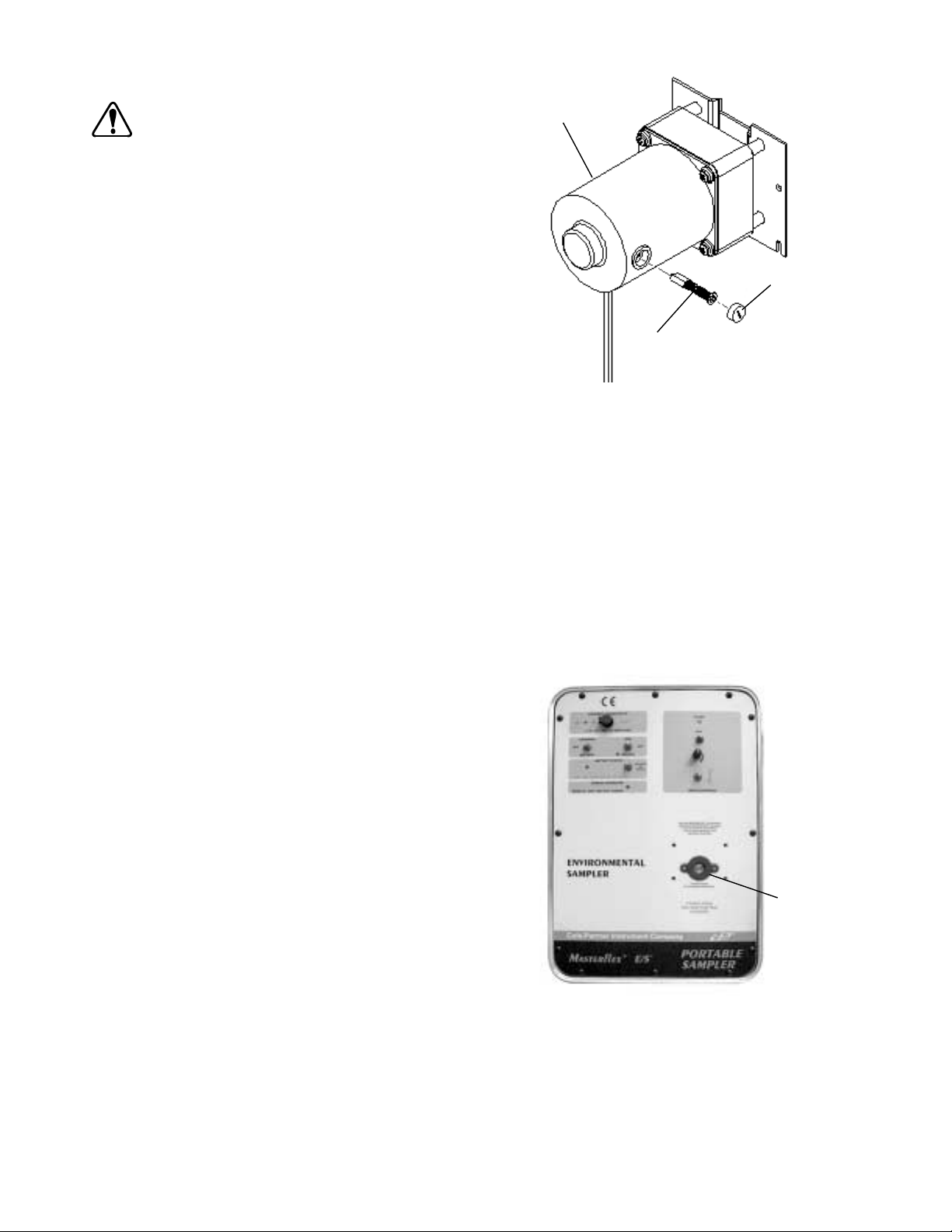
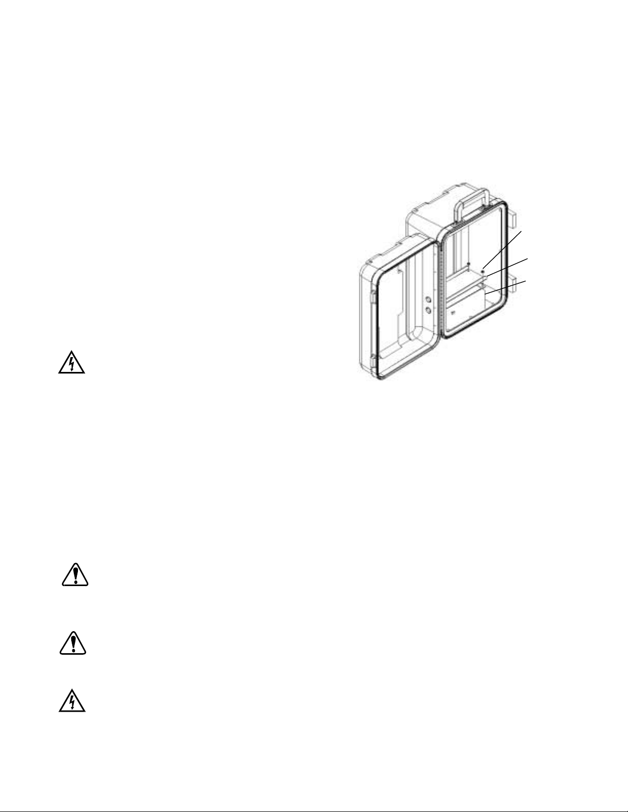
#6-32 SEMS
Nut 4 Places
Bracket—Battery
Holdown
Restraining Bar
Battery: Note
Position of
Terminals
discharged state.
Replacing the Internal Battery (See Figure 2)
DANGER: NEVERshortorconnecttheterminals of the
battery terminals together. Shorting of the
batteryterminalscausesrapid internalheating of the battery resulting in the explosion
of the battery and severe injury or the death
FIGURE 2. BATTERY REPLACEMENT
of the operator.
-
A. Place all control panel switches in the off position and disconnect the AC/DC Power Supply/Converter or other
external power source if present.
B. Removethetwelve(12)screwsholding thecontrolpanelassemblytothehousing usinga#2Phillips screwdriver.
C. Gently remove the control panel from the housing and disconnect the wires from the battery.
D. Removethequick-disconnectterminalssuppliedwith the replacementbatteryandplacethemover the terminals
of the old battery.
E. Using a 5/16 in nut driver, loosen and remove the four (4) nuts and bracket holding the battery restraining bar in
place.
F. Remove the battery.
CAUTION: Do not reverse the connections to the battery. If the battery connections are reversed, damage to
the unit will occur.
G.
Reverse the service process to install the battery. Connect the RED wire to the battery terminal marked +
(positive). Connect the BLACK wire to the battery terminal marked – (negative).
CAUTION: Fully charge the unit before using for the first time. Damage to the internal battery can result if the
battery is in a fully discharged state and operation of the unit is attempted.
H. Fully charge the battery after replacement. See CHARGING THE BATTERY.
DANGER: DO NOT BURN OR INCINERATE THE BATTERY. THE BATTERY MAY EXPLODE CAUSING
SEVERE INJURY OR DEATH OF THE PERSONNEL IN THE AREA. (Dispose of the old battery by
recycling.)
9
Page 11
Motor Brush Check/Replacement (See Figure 3)
WARNING: Turn drive off, remove all the power to the
unit, including the AC/DC Power Sup
-
Motor
ply/Converter, Automotive Power Adapter or
otherexternalpower source ifpresentbefore
servicing the motor brushes. Place the Mode
of Operation Switch (RUN/CHARGE) in the
“CHARGE”positionandallotherswitches in
the off position. This will help prevent acci
dental activation of the drive mechanism so
fingers or loose clothing will not get caught
in the drive mechanism.
Cap Motor Brush
NOTE: The brushes should be checked every 2000 operating
hours or every 6 months or if erratic operation occurs.
Brush Assembly
A. Place all control panel switches in the off position and
disconnecttheAC/DC Power Supply/Converter if pres
-
ent.
B. Remove the twelve (12) screws holding the control
FIGURE 3. MOTOR BRUSH REPLACEMENT
panel assembly to the housing using a #2 Phillips
screwdriver.
C. Gently remove the control panel from the housing and disconnect the wires from the battery.
D. Remove the brushes using a screwdriver and rotate the brush holder 90° CCW. The brush should pop out.
E. Vacuum any brush dust from the brush holder openings.
F. Inspect the brushes. If they are 0.160 in (4 mm) or less in length, replace the brushes.
G. Repeat step D to remove the other brush.
H. Reverse the process to reinstall the brushes, reconnect the battery and install the control panel. Connect the
RED wire to the battery terminal marked + (positive). Connect the BLACK wire to the battery terminal marked
– (negative).
Replacing the Pump Head Sealing Gasket (See Figure 4)
A gasket to seal the Pump Head is supplied with each unit and is
located on the control panel around the drive output shaft. The
gasket will deteriorate with time and frequent pump head
changes. To maintain the integrity of the IP protection of the unit,
the gasket should be changed if deterioration is noted, a leak de
velops, or after one to two years of use, whichever comes first.
To replace the gasket, peel the gasket and its adhesive backing
fromthecontrol panel.Makesureto removeallgasketresidue. An
outline of the gasket is shown on the control panel. Remove the
release liner from the adhesive backing of the new gasket and
position the new gasket within the gasket outline shown on the
control panel.
-
Pump Head
Sealing Gasket
FIGURE 4 PUMP HEAD SEALING GASKET
10
Page 12

TROU BLE SHOOTING
1. The Drive will not op er ate on the in ter nal bat tery power source.
A.
Ver ify that the Power Source Se lec tion Switch (B) , is in the BAT TERY po si tion.
B.
Ver ify that the Mode of Op er a tion Se lec tion Switch (C) , is in the RUN po si tion.
C. Ver ify that the pump head, tub ing size and for mu la tion are cor rect and rec om mended for this drive.
D. If us ing a PTFE pump head, in stall and start the tub ing per the in struc tions in the pump head man ual. Ex ces sive
tight en ing of the oc clu sion bed can jam the drive mech a nism. Tighten the oc clu sion bed grad u ally as in di cated in
the pump head man ual.
E.
Ver ify that the Pump Ro ta tional Se lec tion On/Off Switch (H) , is ei ther in the CW or CCW po si tion for the
desired ro ta tion. The Drive Power In di ca tor (K) in the Drive Con trols sec tion will be il lu mi nated.
F.
Tog gle or ac ti vate the Bat tery Sta tus In di ca tor (F) . If the in di ca tor is RED, re charge the bat tery im me di ately.
You have drained or ex hausted the available power of the in ter nal battery.
G.
If the Bat tery Sta tus In di ca tor (F) does not il lu mi nate, re move the con trol panel and check for loose con nec tions
to the bat tery.
H. Use a dig i tal multi-meter (DMM) set to DC volts to check the bat tery po ten tial. If be low 9 vo lts DC, re place bat tery.
I. If none of the above so lu tions work, contact your au tho rized dealer for ser vice.
2. The Drive will not run us ing ex ter nal power sup plied by the AC/DC Power Sup ply/Con verter.
A.
Ver ify that the Power Source Se lec tion Switch (B) , is in the EX TER NAL po si tion.
B.
Ver ify that the Mode of Op er a tion Se lec tion Switch (C) , is in the RUN po si tion.
C. Ver ify that the pump head, tub ing size and for mu la tion are cor rect and rec om mended for this drive.
D. If us ing a PTFE pump head, in stall and start the tub ing per the in struc tions in the pump head man ual. Ex ces sive
tight en ing of the oc clu sion bed can jam the drive mech a nism. Tighten the oc clu sion bed grad u ally as in di cated in
the pump head man ual.
E.
Ver ify that the Pump Ro ta tional Se lec tion On/Off Switch (H) , is ei ther in the CW or CCW po si tion for the de -
sired ro ta tion. The Drive Power In di ca tor (K) in the Drive Con trols sec tion will be il lu mi nated.
F. Ver ify that the co ax ial plug is fully in serted in the Ex ter nal Power In put of the unit.
G. Ver ify that AC volt age is pres ent in the AC out let to which the AC/DC Power Sup ply/Con verter is con nected.
H.
Ver ify the DC volt age at the 2.5 mm co ax ial con nec tor. Must be at least 13 volts DC. AC/DC Power Sup ply/Con -
verter is not a ser vice able unit and con tains no user ser vice able parts.
I. If none of the above so lu tions work, con tact your au tho rized dealer for ser vice.
3. The Drive will not op er ate us ing the Au to mo tive Power Adapter Ac ces sory.
A.
Ver ify that the Power Source Se lec tion Switch (B) , is in the EX TER NAL po si tion.
B.
Ver ify that the Mode of Op er a tion Se lec tion Switch (C) , is in the RUN po si tion.
C. Ver ify that the pump head, tub ing size and for mu la tion are cor rect and rec om mended for this drive.
D. If us ing a PTFE pump head, in stall and start the tub ing per the in struc tions in the pump head man ual. Ex ces sive
tight en ing of the oc clu sion bed can jam the drive mech a nism. Tighten the oc clu sion bed grad u ally as in di cated in
the pump head man ual.
E.
Ver ify that the Pump Ro ta tional Se lec tion On/Off Switch (H) , is ei ther in the CW or CCW po si tion for the de -
sired ro ta tion. The Drive Power In di ca tor (K) in the Drive Con trols sec tion will be il lu mi nated.
F. Ver ify that the co ax ial plug of the Au to mo tive Power Adapter is fully in serted in the Ex ter nal Power In put of the
drive.
G. Ver ify that the Au to mo tive Power Adapter is fully in serted into the cig a rette lighter on the vehicle.
H. Ver ify that the fuse for the cig a rette lighter is not open or blown.
I. Ver ify the DC volt age at the 2.5 mm co ax ial con nec tor. It must be at least 12 volts DC.
11
Page 13

J.
Verify the polarity of the DC voltage at the 2.5 mm connector. The sleeve is negative, the center is positive. The
drive is protected against polarity reversal and will not operate if the polarities are reversed.
K. If none of the above solutions work, contact your authorized dealer for service.
4. Theinternalbatterychargeindicatoris not illuminated orthebatterywillnot charge using theAC/DCPower
Supply/Converter.
A.
Verify that the Mode of Operation Selection Switch (C), (CHARGE/RUN) is in the CHARGE position.
B. Verifythat the coaxial plug of the AC/DC Power Supply/Converter is fully inserted in the External Power Input of
the unit.
C. Verify thatACvoltageispresentintheACoutlet to which the AC/DC PowerSupply/Converterisconnected.Ver
ify the DC voltage at the 2.5 mm coaxial connector. It must be 13 volts DC minimum.
D. If none of the above solutions work, contact your authorized dealer for service.
5. The internal battery charge indicator is not illuminated or the battery will not charge using the Automotive
Power Adapter Accessory.
A.
Verify that the Power Source Selection Switch (B), (EXTERNAL/BATTERY) is in the EXTERNAL position.
B.
Verify that the Mode of Operation Selection Switch (C), (CHARGE/RUN) is in the RUN position.
C. Verify that the coaxial plug of the Automotive Power Adapter is fully inserted in the External Power Input of the
drive.
D. Verify that the Automotive Power Adapter is fully inserted into the cigarette lighter on the vehicle.
E. Verify that the fuse for the cigarette lighter is not open or blown.
F. Verify the DC voltageat the 2.5 mm coaxial connector. Itmust be 13 volts DC minimum. Verifythe polarity of the
DC voltage at the connector.
G. The drive is protected against polarity reversal and will not operate if the polarities are reversed. The sleeve is
negative, the center is positive.
H. If none of the above solutions work, contact your authorized dealer for service.
-
USER REPLACEMENT PARTS
77120-21 AC/DC Power Supply/Converter 115V AC
77120-26 AC/DC Power Supply/Converter 230V AC
77500-03 Fuse Replacement for Automotive Power Adapter or Auxiliary Power Pack
07571-55 Battery 12V 7.2AH
07571-56 Gasket, Pump Head (pkg. of 6)
07571-57 Sealing Boots, Switches and Speed Control (pkg. of 6)
07571-58 Knob and Cap, Speed Control
07571-59 Motor Brush Replacement Kit, set of two
07571-60 AC/DC Power Supply/Converter 100V AC (Japan)
12
Page 14

ACCESSORIES
06456-10 Tubing Connector, 3/16 in (size L/S®15 and L/S®25 tubing) barbed
06456-20 Tubing Connector, 1/4 in (size L/S
07570-04 Tubing weight, flow-through fits L/S
®
24 tubing) barbed
®
size 15, 24 or 25 tubing
07571-50 Automotive Power Adapter, Current Limited
07571-52 Auxiliary Power Pack w/Charger 115V AC
07571-54 Auxiliary Power Pack w/Charger 230V AC
SPECIFICATIONS
Operating Speed 70 to 400 rpm
Operating Voltage/Frequency:
Model 07571-00 115V AC nominal 50/60 Hz (100–130) V AC @ 120mA AC
12V DC nominal (11–16)V DC @2.4A DC
Model 07571-05 230V AC nominal 50/60 Hz (200–260) V AC @ 60mA AC
12V DC nominal (11–16)V DC @2.4A DC
Number of Pump Heads: 1
Torque Load: 50 oz-in (0.35 N•m), maximum
Direction of Rotation: Clockwise and Counterclockwise
Operating Temperature: 32°F to 122°F (0° to 50°C)
Storage Temperature: −4°F to 149°F (−20°C to 65°C)
Humidity (Non-condensing): 10% to 90%
Altitude 6600 ft. (2000 m)
Dimensions (L x W x H): 11.0 in x 10.25 in x 16.0 in
(27.94 cm x 26.04 cm x 40.64 cm)
Weight: 16.5 pounds (7.49 kg)
Chemical Resistance: High-density polyethylene, clear anodized aluminum,
stainless steel and polyester. All materials withstand
standard solvents.
Enclosure Rating: IP54 per IEC529
Pollution Degree: Degree 2 per IEC664
Installation Category: Category II per IEC664 (local level—appliances, portable
equipment, etc.)
Compliance:
07571-00 115V AC Power Supply AC/DC Converter is UL listed and
CSA approved. Regulatory agency specifications not
applicable to the balance of the unit due to low voltage.
07571-05 230V (for CE Mark):
EU EMC Directive
(EN61326-1/A1: 1998)
13
Page 15
WARRANTY
Use only MASTERFLEX precision tubing with MASTERFLEX pumps to ensure optimum performance. Use of
other tubing may void applicable warranty.
The Manufacturer warrants this product to be free from significant deviations from published specifications. If repair or
adjustmentisnecessarywithinthewarrantyperiod,the problem will be corrected at nochargeifitisnotduetomisuseor
abuseonyourpart, as determinedbytheManufacturer.Repair costs outsidethewarrantyperiod,or those resultingfrom
product misuse or abuse, may be invoiced to you.
The warranty period for this product is noted on the Warranty Card.
PRODUCT RETURN
Tolimit charges and delays, contact the seller orManufacturerfor authorization and shipping instructions before return
ing the product, either within or outside the warranty period.When returning the product, please state the reason for the
return.Foryour protection,packtheproduct carefullyandinsureitagainstpossibledamageorloss.Anydamagesresult
ing from improper packaging are your responsibility.
TECHNICAL ASSISTANCE
If you have any questions about the use of this product, contact the Manufacturer or authorized seller.
Cole-Parmer Instrument Company
625 East Bunker Court
Vernon Hills, Illinois U.S.A. 60061-1844
1-800-MASTERFLEX (627-8373) (U.S. and Canada only)
11 (847) 549-7600 (outside U.S.)
(847) 549-7600 (Local)
FAX (847) 247-2929 (U.S. and Canada only)
11 (847) 549-1700 (Fax outside U.S.)
www.masterflex.com
e-mail: techinfo@coleparmer.com
-
-
Barnant Company
28W092 Commercial Ave.
Barrington, Illinois U.S.A. 60010-2392
1-800-637-3739 (U.S. and Canada only)
11 (847) 381-7050 (outside U.S.)
(847) 381-7050 (Local)
11 (847) 381-7053 (Fax outside U.S.)
(847) 381-7053 (Local Fax)
www.barnant.com
e-mail: barnant@barnant.com
14
Printed in U.S.A.
040601
Page 16

APPENDIX A
RECOMMENDED PUMP HEADS, TUBING SIZES, FORMULATIONS AND MODEL NUMBERS
TUBING MODEL NUMBERS
®
L/S®TYPE
PUMP HEAD
PUMP
MODEL
NO.
Standard 07013-20
07013-21
TUBING
SIZE
SILICONE C-FLEX
13 96400-13
96410-13
®
06424-13 06409-13 06429-13 06485-13 06404-13 06412-13
TYGON
LAB
®
TYGON
LFL
®
PHARMED
®
NORPRENE
07013-52
07014-20
07014-21
14 96400-14
96410-14
06424-14 06409-14 06429-14 06485-14 06404-14 06412-14
07014-52
07015-20
07015-21
15 96400-15
96410-15
06424-15 06409-15
07015-52
07016-20
07016-21
16 96400-16
96410-16
06424-16 06409-16 06429-16 06485-16 06404-16
07016-52
07024-20
07024-21
24 96400-24
96410-24
06424-24
07024-52
QUICK
LOAD
®
07021-22
07021-26
15 96400-15
96410-15
24 96400-24
06424-15 06409-15
06424-24
96410-24
13 96400-13
06424-13 06409-13 06429-13 06485-13 06404-13 06412-13
96410-13
07021-20
07021-24
14 96400-14
96410-14
16 96400-16
06424-14 06409-14 06429-14 06485-14 06404-14 06412-14
06424-16 06409-16 06429-16 06485-16 06404-16
96410-16
25 96400-25
06424-25 06409-25 06429-25
96410-25
EASY-LOAD
®
07518-02
07518-12
07518-62
15 96400-15
96410-15
24 96400-24
96410-24
13 96400-13
06424-15 06409-15
06424-24 06409-24 06429-24
06424-13 06409-13 06429-13 06485-13 06404-13 06412-13
96410-13
07518-00
07518-10
07518-60
14 96400-14
96410-14
16 96400-16
96410-16
25 96400-25
06424-14 06409-14 06429-14 06485-14 06404-14 06412-14
06424-16 06409-16 06429-16 06485-16 06404-16
06424-25 06409-25 06429-25 06485-25 06404-25
96410-25
PTFE 77390-00 4mm 77390-50
PTFE 77390-00 6mm 77390-60
VITON
®
Fluoroelastome
r
PTFE
Note: 96400 prefix indicates Peroxide Cured Silicone Tubing,
96410 prefix indicates Platinum Cured Silicone Tubing.
15
Page 17

APPENDIX B
LIFT VERSUS TUBING SIZE, FORMULATION & FLOW
ALL FLOWS SHOWN ARE ML/MIN @70°F (21.1°C)
LIFT
FEET
0
12 635 690 710
TUBING
SIZE
15
SILICONE
C-FLEX
675 740 740
25 290 210 570
0
12 730 955 1030
24
25
0
12 260 625 680 690
25
25
1085 1060 1040
15′ Max LIFT
750 825 785 740
15′ Max LIFT
0
12 29
4 mm
25 20
0
12 31
6 mm
25 19
Notes: 1. The flows shown above were generated on an EASY-LOAD pump.
2. Average barometric pressure is 740 mm Hg.
3. Flows shown are nominal or averaged.
4. PTFE Tubing Pump is being run @ 400 rpm, which is above its recommended rpm range; this is for intermittent use
(10–15 minutes) only and will result in shorter tubing life. For continuous use, do not exceed 300 rpm. Reduce flows by 33%
for use at 300 rpm.
®
TYGON
LAB
560 670
130 365 345
TYGON
LFL
®
NORPRENE
PHARMED
®
PTFE
30
84
16
Page 18

TABLE DES MATIÈRES
Intitulé Page
MESURES DE SÉCURITÉ . . . . . . . . . . . . . . . . . . . . . . . . . . . . . . . . . . . . . . . . . . . . . . . . . . . . . . . . . . . . . . . . . . . . . . . . 18
INTRODUCTION ET DESCRIPTION GÉNÉRALE. . . . . . . . . . . . . . . . . . . . . . . . . . . . . . . . . . . . . . . . . . . . . . . . . . . . . . 19
HAUTEUR D’ASPIRATION. . . . . . . . . . . . . . . . . . . . . . . . . . . . . . . . . . . . . . . . . . . . . . . . . . . . . . . . . . . . . . . . . . . . . . . . 19
INSTALLATION. . . . . . . . . . . . . . . . . . . . . . . . . . . . . . . . . . . . . . . . . . . . . . . . . . . . . . . . . . . . . . . . . . . . . . . . . . . . . . . . . 19
COMMANDES ET FONCTIONS. . . . . . . . . . . . . . . . . . . . . . . . . . . . . . . . . . . . . . . . . . . . . . . . . . . . . . . . . . . . . . . . . . . . 20
FONCTIONNEMENT DE L’ENTRAÎNEMENT . . . . . . . . . . . . . . . . . . . . . . . . . . . . . . . . . . . . . . . . . . . . . . . . . . . . . . . . . 21
1. Sélection du mode de fonctionnement . . . . . . . . . . . . . . . . . . . . . . . . . . . . . . . . . . . . . . . . . . . . . . . . . . . . . . . . . . 21
2. Instructions d’utilisation . . . . . . . . . . . . . . . . . . . . . . . . . . . . . . . . . . . . . . . . . . . . . . . . . . . . . . . . . . . . . . . . . . . . . . 21
ENTRETIEN . . . . . . . . . . . . . . . . . . . . . . . . . . . . . . . . . . . . . . . . . . . . . . . . . . . . . . . . . . . . . . . . . . . . . . . . . . . . . . . . . . . 23
DÉPANNAGE . . . . . . . . . . . . . . . . . . . . . . . . . . . . . . . . . . . . . . . . . . . . . . . . . . . . . . . . . . . . . . . . . . . . . . . . . . . . . . . . . . 26
PIÈCES DE RECHANGE . . . . . . . . . . . . . . . . . . . . . . . . . . . . . . . . . . . . . . . . . . . . . . . . . . . . . . . . . . . . . . . . . . . . . . . . . 27
ACCESSOIRES . . . . . . . . . . . . . . . . . . . . . . . . . . . . . . . . . . . . . . . . . . . . . . . . . . . . . . . . . . . . . . . . . . . . . . . . . . . . . . . . 28
CARACTÉRISTIQUES TECHNIQUES. . . . . . . . . . . . . . . . . . . . . . . . . . . . . . . . . . . . . . . . . . . . . . . . . . . . . . . . . . . . . . . 28
GARANTIE . . . . . . . . . . . . . . . . . . . . . . . . . . . . . . . . . . . . . . . . . . . . . . . . . . . . . . . . . . . . . . . . . . . . . . . . . . . . . . . . . . . . 29
RETOUR DE MARCHANDISES. . . . . . . . . . . . . . . . . . . . . . . . . . . . . . . . . . . . . . . . . . . . . . . . . . . . . . . . . . . . . . . . . . . . 29
ASSISTANCE TECHNIQUE . . . . . . . . . . . . . . . . . . . . . . . . . . . . . . . . . . . . . . . . . . . . . . . . . . . . . . . . . . . . . . . . . . . . . . . 29
ANNEXE A . . . . . . . . . . . . . . . . . . . . . . . . . . . . . . . . . . . . . . . . . . . . . . . . . . . . . . . . . . . . . . . . . . . . . . . . . . . . . . . . . . . . 30
ANNEXE B . . . . . . . . . . . . . . . . . . . . . . . . . . . . . . . . . . . . . . . . . . . . . . . . . . . . . . . . . . . . . . . . . . . . . . . . . . . . . . . . . . . . 31
FRANÇAIS
C-FLEX—Marque déposée de Consolidated Polymer Technologies, Inc.
NORPRENE, PHARMED, TYGON—Marques déposées de Norton Co.
VITON—Marque déposée de DuPont Dow Elastomers L.L.C.
Les marques accompagnées du symbole ® citées dans cette publication sont déposées aux États-Unis et dans d’autres pays.
17
Page 19
MESURES DE SÉCURITÉ
DANGERS : Ne JAMAISraccorderlaprised’ALIMENTATION ÉLECTRIQUE EXTÉRIEURE qui se trouvesurlepan
neau avant directement au secteur. Un tel raccordement peut occasionner des blessures graves,
voire mortelles, pour l’opérateur et provoquer la destruction de l’appareil. N’utiliser que le bloc
d’alimentation/transformateur alternatif-continu fourni avec l’appareil pour alimenter ce dernier à
partir du secteur.
Ne JAMAIS connecter les cosses de la batterie l’une à l’autre ni les mettre en court-circuit. Une telle
miseencourt-circuitprovoque un échauffementrapideàl’intérieur de labatterieentraînantlui-même
une explosion de cette dernière et des blessures graves, voire mortelles, pour l’opérateur.
Le bloc d’alimentation/transformateur alternatif-continu est conçu pour êtreUTILISÉÀL’INTÉRIEUR
UNIQUEMENT. NE PAS
L’inobservationdecet avertissement peutentraînerun chocélectriqueetdes blessuresgraves,voire
mortelles.
NE PAS BRÛLER NI INCINÉRER LA BATTERIE. ELLE RISQUERAIT D’EXPLOSER ET DE CAUSER
AINSI DES BLESSURES GRAVES, VOIRE MORTELLES, POUR LE PERSONNEL PRÉSENT AUX
ALENTOURS. (Mettre les batteries usagées au rebut en les recyclant.)
CONSEILS DE
PRUDENCE : Ne pas intervertir les connexions à la batterie. Sinon, l’appareil risque d’être endommagé.
Recharger la batterie à fond avant de se servir de l’appareil pour la première fois. La batterie risque
d’être endommagée si elle est complètement déchargée lors d’une tentative de mise en marche de
l’appareil.
L’appareil ne fonctionnera pas correctement et risquera d’être endommagée si elle est trempée ou
plongée dans un liquide.
l’utiliser à l’extérieur pour recharger la batterie ou alimenter l’appareil.
-
L’appareil nefonctionnerapascorrectementetrisquera d’être endommagé en cas d’utilisation de têtes de pompes, de calibres de tubes et de substances autres que ceux qui sont spécifiés dans cette
notice et d’utilisation conjointe d’au moins deux têtes de pompes.
AVERTISSEMENTS : La ruptured’untube peutentraînerune pulvérisationdeliquide refouléparla pompe.Prendre des me-
sures appropriées pour protéger l’opérateur et les appareils.
Arrêter l’entraînement et mettre l’appareil hors tension, y compris le bloc d’alimentation/transforma-
teuralternatif-continu,l’adaptateur d’alimentation surpriseautomobile ou toutesourceextérieurede
courantsinécessaire avant dedéposerou de monterunetête de pompeouun tube. Placerlecommutateur de mode de fonctionnement (RUN/CHARGE, marche/charge) en position « CHARGE » et tous
les autres commutateurs en position d’arrêt. Cela contribuera à empêcher une activation intempes
tive du mécanisme d’entraînement pour qu’il ne risque pas de happer des doigts ou des vêtements
flottants.
AVERTISSEMENT : LIMITATION D’UTILISATION DU PRODUIT
Ce produit n’est pas conçu ni supposé être utilisé dans les applications avec patients, y compris, entre autres, les applications
médicales et dentaires et n’a par conséquent pas été soumis à l’agrément de la FDA.
-
18
Page 20

INTRODUCTION ET DESCRIPTION GÉNÉRALE
L’entraînementdepompe (d’échantillonnagedemilieu)MASTERFLEX®E/S™permetd’obtenir desvitessesdepompe allantde70 à
400 tr/mn dans le sens horaire ou antihoraire pour effectuer la purge des tubes et l’échantillonnage de liquides.
L’entraînement etsonsystèmedechargesont à limitation de courant et sont protégésd’uneinversiondepolaritéde l’alimentation et
des transitoires.
L’entraînement peut fonctionnersurbatterieinterne,êtrealimentéparunesourceextérieure de courant continu de 12 V ou fonction
nersurcourant alternatif de115ou 230 Vlorsqu’ilest utilisé aveclebloc d’alimentation/transformateur alternatif-continuquiest fourni
avec.
L’entraînement est équipé d’une batterieincorporéesansdébordementetd’unsystèmederechargequipermetderechargerlabat
terieàpartir dusecteurà l’aidedubloc d’alimentation/transformateuralternatif-continufourni ouàpartir ducircuit12 Vc.c.d’une auto
mobile s’il est utilisé avec l’adaptateur d’alimentation sur prise automobile.
Il est conçu pour accepter et entraîner une tête de pompe MASTERFLEX
®
L/S®standard, QUICK LOAD®, EASY-LOAD®ou à tubes
PTFE pour le transfert et l’échantillonnage de liquides en clientèle.
L’appareilestenfermé dans uncarterprotecteur àhautevisibilité.Le panneaudecommande et lescommandesd’entraînement n’ont
une protection théorique de niveau IP54 que lorsqu’une tête de pompe est montée sur l’entraînement.
Lorsqu’ilestfermé, l’entraînement flotterapendantaumoins 30minutess’iltombe dansunlacou un coursd’eaupour pouvoir êtreré
cupéré.
HAUTEUR D’ASPIRATION
-
-
-
-
L’ensemble constitué parl’entraînementMASTERFLEX®E/S™ et uneseuletêtedepompeMASTERFLEXpeutaspirerunéchantil
lond’eaujusqu’à7,92m à la verticale. Cettecapacitéestappeléehauteur d’aspiration et est mesuréeentrelasurfacedu liquide et la
tête de pompe.
Cettecapacitéd’aspirationestréduite ouamoindriesileliquide àéchantillonner auneviscositéouune densitésupérieuresàcellesde
l’eau.
INSTALLATION
1. L’entraînement aétéemballéavec soin pourêtreprotégé pendant sontransportdel’usine à sadestinationfinale.Une fois lecarton ouvert, conserver le matériau d’emballage jusqu’à ce que le fonctionnement correct du produit ait été vérifié.
L’entraînement se compose des éléments suivants :
(1) appareil d’entraînement
(1) bloc d’alimentation/transformateur alternatif-continu
(2) clés pour les verrous
(1) notice d’utilisation
(1) carte de garantie
(1) pochette à accessoires
ATTENTION : L’appareil ne fonctionnera pas correctement et risquera d’être endommagée en cas d’utilisation de
têtes depompes,decalibres de tubes et desubstancesautresqueceux qui sont spécifiés danscette
notice et d’utilisation conjointe d’au moins deux têtes de pompes.
AVERTISSEMENT : Arrêter l’entraînement et mettre l’appareil hors tension, y compris le bloc d’alimentation/transforma
teuralternatif-continu,l’adaptateur d’alimentation surpriseautomobile ou toutesourceextérieurede
courantsinécessaire avant dedéposerou de monterunetête de pompeouun tube. Placerlecommu
tateur de mode de fonctionnement (RUN/CHARGE, marche/charge) en position « CHARGE » et tous
les autres commutateurs en position d’arrêt. Cela contribuera à empêcher une activation intempes
tive du mécanisme d’entraînement pour qu’il ne risque pas de happer des doigts ou des vêtements
flottants.
-
-
-
-
2. L’entraînement n’inclut pas de tête de pompe ni de tube. Il peut actionner une (1) des têtes de pompes suivantes :
MASTERFLEX
®
L/S®standard, QUICK LOAD®, EASY-LOAD®ou à tubes PTFE.
Voir l’Annexe A pour les numéros catalogue des têtes de pompes et tubes recommandés.
Voir l’Annexe B pour les débits et la hauteur d’aspiration.
19
Page 21

Choisir l’un des ensembles de tubes et des têtes de pompes MASTERFLEX recommandés et les monter sur l’entraînement
conformément aux instructions données dans la notice de la tête de pompe.
REMARQUE : OPTIMISATION DES PERFORMANCES AU DÉMARRAGE
Lachargelaplusélevée àlaquelleest soumisl’entraînementl’estlorsde lamiseen marcheavecuntubeneuf. Pouroptimiserles
performancesàlamiseen marche dans de telles circonstances,mettrelemécanismed’entraînement sous tension et actionner
l’interrupteur«MAX» pendant 30 secondes. Aprèslamiseen marche avec untubeneuf,relâcher l’interrupteur MAX etréglerla
vitesse de la pompe à l’aide du bouton de réglage de vitesse.
Pouroptimiserlesperformanceset faciliterl’utilisation, ilestrecommandéd’utiliserla têtedepompeEASY-LOADou àtubes PTFE.
AVERTISSEMENT : Laruptured’un tubepeutentraîner unepulvérisationde liquiderefoulépar lapompe.Prendre desme
sures appropriées pour protéger l’opérateur et les appareils.
COMMANDES ET FONCTIONS
Les commandes se divisent en deux sections.
Lescommandesquisetrouvent danslapartiegauchedu panneaude commandesontcellesd’alimentationet demodedefonctionne
ment qui permettent de choisir entre marche de l’entraînement et recharge de la batterie interne.
Lescommandesquisetrouvent dans la partie droitedupanneaudecommande sont celles du mécanismed’entraînementtellesque
celles de sens et de vitesse de rotation.
Les commandes de l’entraînementnefonctionnentquelorsqueleschoixappropriésontétéeffectuésdanslasectiondecommande
d’alimentation (partie gauche).
-
-
A — Prise d’alimentation électrique extérieure
B — Sélecteur de source de courant
F — Témoin de niveau de charge de batterie
E — Interrupteur d’activation
de témoin de niveau de charge
G — Témoin de verrouillage de charge
de batterie
D — Témoin de charge
C — Sélecteur de mode de fonctionnement
FIGURE 1 PANNEAU DE COMMANDE
K — Témoin de mise sous tension
de l’entraînement
J — Max
I — Réglage de vitesse
H — Sélecteur de sens de rotation/
commutateur de marche/arrêt de pompe
Joint d’étanchéité de tête de pompe
A. PRISE D’ALIMENTATION ÉLECTRIQUE EXTÉRIEURE
Prise coaxiale de 2,5 mm permettant d’alimenter l’entraînement en courant continu destiné à recharger la batterie interne ou à
fairefonctionnerl’entraînement àpartird’une source decourantautre quelabatterie interne.Labrochecentrale estpositive(+) et
la douille négative (–).
B. SÉLECTEUR DE SOURCE DE COURANT
Il permet de choisir entre la BATTERIE interne et une source EXTÉRIEURE de courant pour alimenter le mécanisme
d’entraînement.
C. SÉLECTEUR DE MODE DE FONCTIONNEMENT
Il permet de choisir entre MARCHE de la pompe et CHARGE de la batterie.
Remarque: Iln’estpaspossible derechargerla batterie alorsquela pompeestenmarche. Ilestpossible de sélectionnerl’une
oul’autrede ces fonctions,maispasles deuxàlafois. Lorsquelesélecteurest placéenpositionCHARGE, toutes
les autres fonctions sont désactivées.
20
Page 22

D. TÉMOIN DE CHARGE
DÉL verte qui s’allume lorsque l’alimentation en courant se fait à partir d’une source extérieure et que l’appareil a été placé en
mode de charge de batterie.
E. INTERRUPTEUR D’ACTIVATION DE TÉMOIN DE NIVEAU DE CHARGE DE BATTERIE
Ilactiveletémoinde niveaude chargedebatterielorsqu’onle faitbasculerverslehaut oule basetqu’onlemaintient enfoncé.
F. TÉMOIN DE NIVEAU DE CHARGE DE BATTERIE
Il s’allume de trois façons différentes pour indiquer la capacité de la batterie.
Vert stable = la batterie est chargée à fond.
Vert clignotant = la batterie est partiellement déchargée, avec une capacité restante de 50 % au maximum.
Rouge = la batterie est complètement déchargée et doit être rechargée immédiatement.
G. TÉMOIN DE VERROUILLAGE DE CHARGE
Ils’allumelorsquelatempérature ambianterégnantàl’intérieurdu carteresttropélevéepour chargerla batteriesansdanger.Son
allumage indique que le circuit de charge a été désactivé. Le système peut fonctionner mais ne peut être rechargé.
H. SÉLECTEUR DE SENS DE ROTATION/COMMUTATEUR DE MARCHE/ARRÊT DE POMPE
Cecommutateurpermetdemettre la pompe enmarcheetdel’arrêter, ainsi que desélectionnerlesensde rotation de lapompe:
horaire ou antihoraire. La position centrale est celle d’arrêt.
I. RÉGLAGE DE VITESSE
Le potentiomètre à un (1) tour permet de régler la vitesse de la pompe. Le tourner dans le sens horaire pour augmenter cette vi
tesse et dans le sens antihoraire pour la réduire.
J. MAX
Interrupteurdeshuntagede la circuiteriederéglagede vitesse permettantdefairetourner la pompeàsavitesse maximum nomi
nale. Il peut servir à amorcer ou purger le tube suivant la position du sélecteur de sens de rotation (H).
K. TÉMOIN DE MISE SOUS TENSION DE L’ENTRAÎNEMENT
DÉLquis’allume lorsque lesélecteurde sensderotation(MARCHE/ARRÊT) estdansuneposition autrequecelled’arrêt. Cetal
lumage indique que le mécanisme d’entraînement est sous tension.
-
-
-
FONCTIONNEMENT DE L’ENTRAÎNEMENT
1. Sélection du mode de fonctionnement
L’appareil peut fonctionner dans trois modes différents :
A. Charge de la batterie interne, ce qui désactive toutes les autres fonctions.
B. Fonctionnement de l’entraînement sur batterie interne.
C. Fonctionnement de l’entraînement à partir d’une source extérieure de courant.
2. Instructions d’utilisation
Charge de la batterie interne à l’aide du bloc d’alimentation/transformateur alternatif-continu ou d’une autre source exté
rieure de courant :
ATTENTION : Recharger la batterie à fond avant de se servir de l’appareil pour la première fois. La batterie risque
d’être endommagée si elle est complètement déchargée lors d’une tentative de mise en marche de
l’appareil.
A.
Connecterlebloc d’alimentation/transformateuralternatif-continuà l’entraînementenrelevant lecouverclede laprise
d’ALIMENTATION ÉLECTRIQUE EXTÉRIEURE (A) et enfoncer la fiche d’alimentation coaxiale de 2,5 mm dans la prise.
(Voir Figure 1.)
DANGER : Ne JAMAISraccorderlaprised’ALIMENTATION ÉLECTRIQUE EXTÉRIEURE qui se trouvesurlepan
neau avant directement au secteur. Un tel raccordement peut occasionner des blessures graves,
voire mortelles, pour l’opérateur et provoquer la destruction de l’appareil. N’utiliser que le bloc
d’alimentation/transformateur alternatif-continu fourni avec l’appareil pour alimenter ce dernier à
partir du secteur.
B.
Raccorder le blocd’alimentation/transformateuralternatif-continuausecteur. Placer le sélecteur de source de cou
rant (B) (EXTERNAL/BATTERY, alimentation extérieure/batterie) dans la position « BATTERY ».
C.
Placer le sélecteur de mode de fonctionnement (C) (RUN/CHARGE, marche/charge) en position « CHARGE ».
D.
Le témoin CHARGE s’allume.
E.
Charger la batterie pendant 8 à 12 heures.
-
-
-
21
Page 23

Fonctionnement de la pompe sur la batterie interne
DANGER : Le bloc d’alimentation/transformateur alternatif-continu est conçu pour êtreUTILISÉÀL’INTÉRIEUR
UNIQUEMENT. NE PAS
l’utiliser à l’extérieur pour recharger la batterie ou alimenter l’appareil.
L’inobservationdecet avertissement peutentraînerun chocélectriqueetdes blessuresgraves,voire
mortelles.
ATTENTION : Recharger la batterie à fond avant de se servir de l’appareil pour la première fois. La batterie risque
d’être endommagée si elle est complètement déchargée lors d’une tentative de mise en marche de
l’appareil.
A.
Placerlesélecteurdesourcede courant (B) (EXTERNAL/BATTERY, alimentation extérieure/batterie)danslaposition
« BATTERY ».
B.
Placer le sélecteur de mode de fonctionnement (C) (RUN/CHARGE, marche/charge) en position « RUN ».
C.
Tourner le sélecteur de sens de rotation/commutateur de marche/arrêt de pompe (H) dans le sens horaire ou antiho
raire. (Voir Figure 1.) (Lors d’un changement de sens, commencer par mettre l’appareil hors tension en plaçant le sélecteur
dans sa position centrale, qui est celle d’ARRÊT.)
D.
Réglerledébit de lapompeà l’aide dupotentiomètreà 1 tourderéglage de vitesse(I)en tournantcelui-cidansle sensho
raire pour augmenter le débit ou dans le sens antihoraire pour le réduire.
E.
Pour «amorcerletube », basculer l’interrupteur «MAX»(J) vers le hautouverslebas pour faire tournerlapompeàla vi
tesse maximum.
Vérification de la capacité de batterie disponible
REMARQUE : Contrôler la batterie interne lorsque la pompe est en marche pour obtenir la mesure la plus exacte.
A.
Placerlesélecteurdesourcede courant (B) (EXTERNAL/BATTERY, alimentation extérieure/batterie)danslaposition
« BATTERY ».
B.
Placer le sélecteur de mode de fonctionnement (C) (RUN/CHARGE, marche/charge) en position « RUN ».
C.
Tourner le sélecteur de sens de rotation/commutateur de marche/arrêt de pompe (H) dans le sens horaire ou antihoraire. (Voir Figure 1.) (Lors d’un changement de sens, commencer par mettre l’appareil hors tension en plaçant le sélecteur
dans sa position centrale, qui est celle d’ARRÊT.)
D.
Basculer l’interrupteur d’activation de témoindeniveaudechargedebatterieverslehaut ou le bas et le maintenir enfoncé. Le témoin s’allume.
Vert stable = la batterie est chargée à fond.
Vert clignotant = la batterie est partiellement déchargée, avec une capacité restante de 50 % au maximum.
Rouge = la batterie est complètement déchargée et doit être rechargée immédiatement.
-
-
-
Fonctionnement de la pompe sur batterie 12 V extérieure, avec adaptateur d’alimentation sur prise automobile ou à partir d’une autre source extérieure de courant continu
DANGER : Le bloc d’alimentation/transformateur alternatif-continu est conçu pour êtreUTILISÉÀL’INTÉRIEUR
UNIQUEMENT. NE PAS
l’utiliser à l’extérieur pour recharger la batterie ou alimenter l’appareil.
L’inobservationdecet avertissement peutentraînerun chocélectriqueetdes blessuresgraves,voire
mortelles.
ATTENTION : Recharger la batterie à fond avant de se servir de l’appareil pour la première fois. La batterie risque
d’être endommagée si elle est complètement déchargée lors d’une tentative de mise en marche de
l’appareil.
A.
Placerlesélecteurdesourcede courant (B) (EXTERNAL/BATTERY, alimentation extérieure/batterie)danslaposition
« EXTERNAL ».
B.
Placer le sélecteur de mode de fonctionnement (C) (RUN/CHARGE, marche/charge) en position « RUN ».
C.
Tourner le sélecteur de sens de rotation/commutateur de marche/arrêt de pompe (H) dans le sens horaire ou antiho
raire. (Voir Figure 1.) (Lors d’un changement de sens, commencer par mettre l’appareil hors tension en plaçant le sélecteur
dans sa position centrale, qui est celle d’ARRÊT.)
D.
Réglerledébit de lapompeà l’aide dupotentiomètreà 1 tourderéglage de vitesse(I)en tournantcelui-cidansle sensho
raire pour augmenter le débit ou dans le sens antihoraire pour le réduire.
E.
Pour «amorcerletube », basculer l’interrupteur «MAX»(J) vers le hautouverslebas pour faire tournerlapompeàla vi
tesse maximum.
-
-
-
22
Page 24

Fonctionnement de la pompe sur secteur
DANGER : Ne JAMAISraccorderlaprised’ALIMENTATION ÉLECTRIQUE EXTÉRIEURE qui se trouvesurlepan
neau avant directement au secteur. Un tel raccordement peut occasionner des blessures graves,
voire mortelles, pour l’opérateur et provoquer la destruction de l’appareil. N’utiliser que le bloc
d’alimentation/transformateur alternatif-continu fourni avec l’appareil pour alimenter ce dernier à
partir du secteur.
DANGER : Le bloc d’alimentation/transformateur alternatif-continu est conçu pour êtreUTILISÉÀL’INTÉRIEUR
UNIQUEMENT. NE PAS
l’utiliser à l’extérieur pour recharger la batterie ou alimenter l’appareil.
L’inobservationdecet avertissement peutentraînerun chocélectriqueetdes blessuresgraves,voire
mortelles.
A.
Connecterlebloc d’alimentation/transformateuralternatif-continuà l’entraînementenrelevant lecouverclede laprise
d’ALIMENTATION ÉLECTRIQUE EXTÉRIEURE (A) et enfoncer la fiche d’alimentation coaxiale de 2,5 mm dans la prise.
(Voir Figure 1.)
B.
Raccorder le blocd’alimentation/transformateuralternatif-continuausecteur. Placer le sélecteur de source de cou
rant (B) (EXTERNAL/BATTERY, alimentation extérieure/batterie) dans la position « EXTERNAL ».
C.
Placer le sélecteur de mode de fonctionnement (C) (RUN/CHARGE, marche/charge) en position « RUN ».
D.
Tourner le sélecteur de sens de rotation/commutateur de marche/arrêt de pompe (H) dans le sens horaire ou antiho
raire. (Voir Figure 1.) (Lors d’un changement de sens, commencer par mettre l’appareil hors tension en plaçant le sélecteur
dans sa position centrale, qui est celle d’ARRÊT.)
E.
Réglerledébit de lapompeà l’aide dupotentiomètreà 1 tourderéglage de vitesse(I)en tournantcelui-cidansle sensho
raire pour augmenter le débit ou dans le sens antihoraire pour le réduire.
F.
Pour « amorcerletube»,basculerl’interrupteur « MAX » (J) vers le haut ou verslebasetlemaintenirdans cette position
pour faire tourner la pompe à la vitesse maximum.
-
-
-
-
ENTRETIEN
ATTENTION : L’appareil ne fonctionnera pas correctement et risquera d’être endommagée si elle est trempée ou
plongée dans un liquide.
Nettoyage
Nettoyer les surfaces extérieure et intérieure du carter et le panneau de commande avec un chiffon sec ou mouillé et un détergent
doux. Ne jamais les plonger dans un liquide ni trop les mouiller.
Batterie interne
La batterieinterneestàl’abridesdébordementset scellée, ne comporte aucune pièce ou composant susceptibled’êtreentretenuet
est fabriquée pour de nombreuse années de service lorsqu’elle est maintenue en bon état.
ATTENTION : Recharger la batterie à fond avant de se servir de l’appareil pour la première fois. La batterie risque
d’être endommagée si elle est complètement déchargée lors d’une tentative de mise en marche de
l’appareil.
A. Recharger la batterie à fond avant de se servir de l’appareil pour la première fois.
B. Entreposer l’appareil à la température ambiante si possible.
C. Toujours entreposer l’appareil avec la batterie chargée à fond.
D. La batterie se décharge spontanément en partie au bout d’un certain temps. Le taux de déchargement spontané augmente
avec la température. Il est recommandé de faire fonctionner l’appareil pendant au moins 2 heures tous les six mois, puis de
recharger la batterie pendant la nuit. Cela préserve la durée de service maximum potentielle de la batterie interne.
E. Nepasrecharger labatteriependantplusde24heures.Une rechargeinutilementprolongée provoqueraunéchauffement in
terneetune possible défaillanceprématuréedela batterie.Labatteriese rechargeàfonden8à12heureslorsqu’elleest en
tièrementdéchargée.Une foislabatterie chargéeàfond,soncircuitdecharge/régulationla faitpasseren modedecharge de
maintien pour empêcher une recharge excessive.
-
-
Recharge de la batterie interne à partir du secteur
DANGER : Ne JAMAISraccorderlaprised’ALIMENTATION ÉLECTRIQUE EXTÉRIEURE qui se trouvesurlepan
neau avant directement au secteur. Un tel raccordement peut occasionner des blessures graves,
voire mortelles, pour l’opérateur et provoquer la destruction de l’appareil. N’utiliser que le bloc
d’alimentation/transformateur alternatif-continu fourni avec l’appareil pour alimenter ce dernier à
partir du secteur.
23
-
Page 25
A.
Connecterlebloc d’alimentation/transformateuralternatif-continuà l’entraînementenrelevant lecouverclede laprise
d’ALIMENTATION ÉLECTRIQUE EXTÉRIEURE (A) et enfoncer la fiche d’alimentation coaxiale de 2,5 mm dans la prise.
(Voir Figure 1.)
B.
Raccorder le bloc d’alimentation/transformateur alternatif-continu au secteur.
C.
Placer le sélecteur de mode de fonctionnement (C) (RUN/CHARGE, marche/charge) en position « CHARGE ».
D. Le témoin de charge s’allume lorsque le circuit de charge est mis sous tension.
E. La batterie se recharge à fond en 8 à 12 heures lorsqu’elle est entièrement déchargée.
Recharge de la batterie interne à l’aide d’une batterie 12 V extérieure, de l’adaptateur d’alimentation sur prise automo
bile 07571-50 ou d’une autre source de courant continu
A.
Connecter la source extérieure de courant en relevant le
couvercle de la prise d’ALIMENTATION ÉLECTRIQUE
EXTÉRIEURE (A) et enfoncer la fiche d’alimentation
coaxiale de 2,5 mm dans la prise. (Voir Figure 1.)
B. Raccorder l’adaptateur d’alimentation sur prise automobile
07571-50 à l’allume-cigarette du véhicule.
C.
Placer le sélecteur de mode de fonctionnement (C)
(RUN/CHARGE, marche/charge) en position
« CHARGE ».
D. Le témoin decharges’allumelorsque le circuitdechargeest
mis sous tension.
E. La batterie se recharge à fond en8à12heures lorsqu’elle
Écrou n° 6-32
SEMS en quatre
endroits
Entretoise—
barre de
retenue de
batterie
Batterie :
noter
la position
des cosses
est entièrement déchargée.
Remplacement de la batterie interne (voir Figure 2)
DANGER : Ne JAMAIS connecter les cosses de la
batterie l’une à l’autre ni les mettre en
court-circuit. Une telle mise en
court-circuit provoque un échauffement
rapide à l’intérieur de la batterie entraî-
FIGURE 2. REMPLACEMENT DE LA BATTERIE
nantlui-mêmeune explosion decettedernière et des blessures graves, voire
mortelles pour l’opérateur.
-
A. Placertousles commutateurs dupanneaude commande enpositiond’arrêt etdébrancherlebloc d’alimentation/transforma-
teur alternatif-continu ou toute autre source extérieure de courant le cas échéant.
B. Retirer les douze (12) vis fixant le panneau de commande au carter à l’aide d’un tournevis cruciforme n° 2.
C. Déposer le panneau de commande du carter avec précaution et débrancher les fils de la batterie.
D. Retirer lesconnecteursrapidesfournisavec labatteriederechangeetlesplacer par-dessuslescossesdela batterieusagée.
E. Desserrerlesquatre (4) écrousàl’aide d’unecléàdouille de5/16po, puislesretirerainsi quel’entretoisemaintenant la barre
de retenue de batterie en place.
F. Retirer la batterie.
ATTENTION : Ne pas intervertir les connexions à la batterie. Sinon, l’appareil risque d’être endommagé.
G.
Procéderdansl’ordreinversepour mettre la batteriederechangeenplace. Raccorder le fil ROUGEàlacosse de batterie
marquée + (positive) et le fil NOIR à la cosse marquée – (négative).
ATTENTION : Recharger la batterie à fond avant de se servir de l’appareil pour la première fois. La batterie risque
d’être endommagée si elle est complètement déchargée lors d’une tentative de mise en marche de
l’appareil.
H. Recharger la batterie à fond une fois le remplacement effectué. Voir RECHARGE DE LA BATTERIE.
DANGER : NE PAS BRÛLER NI INCINÉRER LA BATTERIE. ELLES RISQUERAIT D’EXPLOSER ET DE CAUSER
AINSI DES BLESSURES GRAVES, VOIRE MORTELLES, POUR LE PERSONNEL PRÉSENT AUX
ALENTOURS. (Mettre les batteries usagées au rebut en les recyclant.)
24
Page 26

Contrôle/remplacements de balais du moteur (voir Figure 3)
AVERTISSEMENT : Arrêter l’entraînement et mettre l’appareil hors
tension, ycomprislebloc d’alimentation/trans
-
Moteur
formateur alternatif-continu, l’adaptateur
d’alimentation sur prise automobile ou toute
source extérieure de courant si nécessaire
avant de déposer ou de monter une tête de
pompe ou un tube. Placer le commutateur de
mode de fonctionnement (RUN/CHARGE,
marche/charge) en position « CHARGE » et
tous les autres commutateurs en position
d’arrêt. Cela contribuera à empêcher une acti
-
Capuchon de
balais de moteur
vation intempestive du mécanisme
d’entraînement pourqu’ilnerisque pas de hap
per des doigts ou des vêtements flottants.
-
Ensemble de balais
REMARQUE : il convient de contrôler les balais toutes les 2000 heures de
fonctionnementoutousles6 mois,ou encasdefonctionnementirrégulier.
A. Placer tous les commutateurs du panneau de commande en
position d’arrêt et débrancher le bloc d’alimentation/transforma
teur alternatif-continu ou toute autre source extérieure de courant
FIGURE 3. REMPLACEMENT DES BALAIS
-
DU MOTEUR
le cas échéant.
B. Retirer les douze (12) vis fixant le panneau de commande au carter à l’aide d’un tournevis cruciforme n° 2.
C. Déposer le panneau de commande du carter avec précaution et débrancher les fils de la batterie.
D. Retirer lesbalaisàl’aided’un tourneviset fairetournerleporte-balaisde 90°danslesensantihoraire. Unbalaidoits’éjecter.
E. Enlever toute poussière de balais des ouvertures du porte-balais à l’aide d’un aspirateur.
F. Examiner les balais. Les remplacer si leur longueur ne dépasse pas 4 mm.
G. Répéter l’opération D pour retirer l’autre balai.
H. Procéder dans l’ordreinversepour remettrelesbalaisen place,reconnecterla batterie etremettrele panneaudecommande
enplace.Raccorderlefil ROUGEà lacossedebatteriemarquée +(positive)etlefil NOIRà lacossemarquée–(négative).
Remplacement du joint d’étanchéité de tête de pompe (voir Figure 4)
Unjointdestinéàassurerl’étanchéité de la tête depompeestfourniavec
chaque appareil et se trouve sur le panneau de commande, autour de
l’arbredesortied’entraînement. Il se détérioreauboutd’un certain temps
et en cas de changements fréquents de tête de pompe. Afin de maintenir
l’intégrité de la protection IP de l’appareil, il convient de remplacer le joint
sidessignesdedétérioration apparaissent,s’ilfuitouau boutdedeuxans
d’utilisation, suivant le cas.
Pour remplacer le joint, le décoller ainsi que sa couche dorsale adhésive
du panneau de commande. Veiller à enlever tous les résidus de joint. Un
contourdujointapparaîtsurlepanneau de commande. Décoller la garni
ture delacouchedorsaleadhésivedu joint neuf et placer ce dernier dans
leslimitesducontourde jointapparaissant surlepanneaudecommande.
-
FIGURE 4 JOINT D’ÉTANCHÉITÉ
DE TÊTE DE POMPE
Joint d’étanchéité
de tête de pompe
25
Page 27

DÉPANNAGE
1. L’entraînement ne fonc tionne pas sur bat terie in terne.
A. Vé ri fier que le sé lec teur de source de cou rant (B) est en po si tion BATTERY (bat terie).
B.
Vé ri fier que le sé lec teur de mode de fonc tion ne ment (C) est en po si tion RUN (marche).
C. Vé ri fier que la tête de pompe, le ca libre de tube et la subs tance pompée sont cor rects et re c om man dés pour cet en traî ne ment.
D. En cas d’utilisation d’une tête de pompe PTFE, rac cor der le tube et com men cer à l’utiliser conf or mé ment aux ins truc tions
don nées dans la no tice de la tête de pompe. Un ser rage ex ces sif de la chape de fer me ture peu t pro vo quer un grip page du
mé ca nisme d’entraînement. Ser rer la chape de fer me ture pro gres si ve ment comme in di qué dan s la no tice de la tête de
pompe.
E.
Vé ri fier que le sé lec teur de sens de ro ta tion/com mu ta teur de marche/ar rêt de pompe (H) est tour né dans le sens
horaire ou an ti ho raire sui vant le sens de ro ta tion dé si ré. Le té moin de mise sous ten sion (K) si tué dans la partie où se
trou vent les com man des d’entraînement est al lu mé.
F.
Bas cu ler l’interrupteur d’activation du té moin de ni veau de charge de bat terie (F) pour ac ti ver ce der nier. Si le té moin est
ROUGE, re char ger la bat terie im mé dia te ment car cela si gnifie que la ca pa ci té de la bat t erie in terne a été épuisée.
G.
Si le té moin de ni veau de charge de bat terie (F) ne s’allume pas, dé po ser le pan neau de com mande et vé ri fier les
connexions à la bat terie pour voir si el les ont du jeu.
H. Con trô ler la ca pa ci té de la bat terie à l’aide d’un con trô leur uni ver sel nu mé rique ré gl é sur la ten sion de cou rant conti nu. Si elle
est in fé rieur à 9 volts, rem pla cer la bat terie.
I. Si au cune des so lu tions ci-dessus ne per met de ré soudre le pro blème, s’adresser au re ven deu r agréé.
2. L’entraînement ne fonc tionne pas sur le cou rant four ni par le bloc d’alimentation/trans for ma teur al ter na tif-continu.
A.
Vé ri fier que le sé lec teur de source de cou rant (B) est en po si tion EXTERNAL (ali men ta tion ex té rieure).
B.
Vé ri fier que le sé lec teur de mode de fonc tion ne ment (C) est en po si tion RUN (marche).
C. Vé ri fier que la tête de pompe, le ca libre de tube et la subs tance pompée sont cor rects et re c om man dés pour cet en traî ne -
ment.
D. En cas d’utilisation d’une tête de pompe PTFE, rac cor der le tube et com men cer à l’utiliser conf or mé ment aux ins truc tions
don nées dans la no tice de la tête de pompe. Un ser rage ex ces sif de la chape de fer me ture peu t pro vo quer un grip page du
mé ca nisme d’entraînement. Ser rer la chape de fer me ture pro gres si ve ment comme in di qué dan s la no tice de la tête de
pompe.
E.
Vé ri fier que le sé lec teur de sens de ro ta tion/com mu ta teur de marche/ar rêt de pompe (H) est tour né dans le sens ho -
raire ou an ti ho raire sui vant le sens de ro ta tion dé si ré. Le té moin de mise sous ten sion (K) si tué dans la partie où se trou -
vent les com man des d’entraînement est al lu mé.
F. Vé ri fier que la fiche coaxiale est com plè te ment en foncée dans la prise d’alimentation élec tr ique ex té rieure de l’appareil.
G. Vé ri fier que la prise sec teur dans la quelle est bran ché le bloc d’alimentation/trans for ma te ur al ter na tif-continu est sous
tension.
H. Vé ri fier que le connec teur coaxial de 2,5 mm re çoit du cou rant conti nu. La ten sion de ce der nier doit être d’au moins 13 volts.
Le bloc d’alimentation/trans for ma teur al ter na tif-continu ne peut faire l’objet d’aucun en tre tien et ne contient au cune
pièce qui le peut.
I. Si au cune des so lu tions ci-dessus ne per met de ré soudre le pro blème, s’adresser au re ven deu r agréé.
3. L’entraînement ne fonc tionne pas avec l’adaptateur d’alimentation sur prise au to mo bile.
A.
Vé ri fier que le sé lec teur de source de cou rant (B) est en po si tion EXTERNAL (ali men ta tion ex té rieure).
B.
Vé ri fier que le sé lec teur de mode de fonc tion ne ment (C) est en po si tion RUN (marche).
C. Vé ri fier que la tête de pompe, le ca libre de tube et la subs tance pompée sont cor rects et re c om man dés pour cet en traî ne ment.
D. En cas d’utilisation d’une tête de pompe PTFE, rac cor der le tube et com men cer à l’utiliser conf or mé ment aux ins truc tions
don nées dans la no tice de la tête de pompe. Un ser rage ex ces sif de la chape de fer me ture peu t pro vo quer un grip page du
mé ca nisme d’entraînement. Ser rer la chape de fer me ture pro gres si ve ment comme in di qué dan s la no tice de la tête de
pompe.
E.
Vé ri fier que le sé lec teur de sens de ro ta tion/com mu ta teur de marche/ar rêt de pompe (H) est tour né dans le sens ho -
raire ou an ti ho raire sui vant le sens de ro ta tion dé si ré. Le té moin de mise sous ten sion (K) si tué dans la partie où se trou -
vent les com man des d’entraînement est al lu mé.
F. Vé ri fier que la fiche coaxiale de l’adaptateur d’alimentation sur prise au to mo bile/est com plè te ment en foncée dans la prise
d’alimentation élec trique ex té rieure de l’entraînement.
G. Vé ri fier que l’adaptateur d’alimentation sur prise au to mo bile est com plè te ment en fon cé da ns l’allume-cigarette du vé hi cule.
H. Vé ri fier que le fu sible de l’allume-cigarette n’est pas ou vert ni gril lé.
I. Vé ri fier que le connec teur coaxial de 2,5 mm re çoit du cou rant conti nu. La ten sion de ce der nier doit être d’au moins 12 volts.
26
Page 28

J. Vérifierlapolarité ducourantcontinuprésentau niveauduconnecteurde2,5 mm.Ladouilleestnégative etlabrochecentrale
positive.L’entraînementestprotégéd’une inversionde lapolaritéet nefonctionne pasencasd’inversionde polarité.
K. Si aucune des solutions ci-dessus ne permet de résoudre le problème, s’adresser au revendeur agréé.
4. Le témoin de charge de batterie interne n’est pas allumé ou la batterie ne peut se charger à l’aide du bloc
d’alimentation/transformateur alternatif-continu.
A.
Vérifier que le sélecteur de mode de fonctionnement (C) (CHARGE/RUN, charge/marche) est en position CHARGE.
B. Vérifier que la fiche coaxiale du bloc d’alimentation/transformateur alternatif-continu est complètement enfoncée dans la
prise d’alimentation électrique extérieure de l’appareil.
C. Vérifier que la prise secteur dans laquelle est branché le bloc d’alimentation/transformateur alternatif-continu est sous ten
sion. Vérifier que le connecteur coaxial de 2,5 mm reçoit du courant continu. La tension de ce dernier doit être d’au moins
13 volts.
D. Si aucune des solutions ci-dessus ne permet de résoudre le problème, s’adresser au revendeur agréé.
5. Le témoin de charge de batterie interne n’est pas allumé ou la batterie ne peut se charger à l’aide de l’adaptateur
d’alimentation sur prise automobile.
A.
Vérifierquele sélecteurdesource decourant(B) (EXTERNAL/BATTERY,alimentationextérieure/batterie) estenposi
tion EXTERNAL.
B.
Vérifier que le sélecteur de mode de fonctionnement (C) (CHARGE/RUN, charge/marche) est en position RUN.
C. Vérifier que la fiche coaxiale de l’adaptateur d’alimentation sur prise automobile est complètement enfoncée dans la prise
d’alimentation électrique extérieure de l’appareil.
D. Vérifier quel’adaptateurd’alimentationsurprise automobileestcomplètementenfoncédansl’allume-cigarettedu véhicule.
E. Vérifier que le fusible de l’allume-cigarette n’est pas ouvert ni grillé.
F. Vérifier que le connecteurcoaxialde2,5mm reçoit du courantcontinu.Latension de ce dernier doitêtred’aumoins 13 volts.
Vérifier la polarité du courant continu présent au niveau du connecteur.
G L’entraînement estprotégéd’uneinversionde lapolaritéetnefonctionne pasencasd’inversionde polarité.Ladouille estné-
gative et la broche centrale positive.
H. Si aucune des solutions ci-dessus ne permet de résoudre le problème, s’adresser au revendeur agréé.
-
-
PIÈCES DE RECHANGE
77120-21 Bloc d’alimentation/transformateur alternatif-continu 115 V c.a.
77120-26 Bloc d’alimentation/transformateur alternatif-continu 230 V c.a.
77500-03 Fusible de rechange pour adaptateur d’alimentation sur prise automobile ou bloc d’alimentation auxiliaire
07571-55 Batterie 12 V 7,2 Ah
07571-56 Joint, tête de pompe (paquet de 6)
07571-57 Manchons isolants, commutateurs et bouton de réglage de vitesse (paquet de 6)
07571-58 Bouton et capuchon, bouton de réglage de vitesse
07571-59 Kit de remplacement de balais de moteur, jeu de deux
07571-60 Bloc d’alimentation/transformateur alternatif-continu 100 V c.a. (Japon)
27
Page 29

ACCESSOIRES
06456-10 Raccord de tube, 3/16 po (tubes des calibres L/S®15 et L/S®25), cannelé
®
06456-20 Raccord de tube, 1/4 po (tubes de calibre L/S
07570-04 Contrepoids pour tubes, bille percée adaptée au montage sur les tubes L/S
24), cannelé
®
de calibre 15, 24 ou 25
07571-50 Adaptateur d’alimentation sur prise automobile, limitation de courant
07571-52 Bloc d’alimentation auxiliaire avec chargeur 115 V c.a.
07571-52 Bloc d’alimentation auxiliaire avec chargeur 230 V c.a.
CARACTÉRISTIQUES TECHNIQUES
Vitesse de fonctionnement 70 à 400 tr/mn
Tension/fréquence de fonctionnement :
Modèle 07571-00 Tension nominale de 115 V c.a.,
Modèle 07571-05 Tension nominale de 230 V c.a.,
Nombre de têtes de pompes : 1
Couple : 0,35 N•m max.
Sens de rotation : Horaire ou antihoraire
Température de fonctionnement : 0 à 50 °C
Température d’entreposage : –20 à 65 °C
Humidité (sans condensation) : 10 à 90 %
Altitude : 2000 m
Dimensions (L ⫻ l ⫻ H) : 27,94 ⫻ 26,04 ⫻ 40,64 cm
Poids : 7,49 kg
Résistance aux attaques chimiques : Polyéthylène haute densité, aluminium pur anodisé, acier
Protection théorique du carter : IP54 (IEC529)
Degré de pollution : Degré 2 (IEC664)
Catégorie d’installation : Catégorie II (IEC664) (appareils à installation locale,
Conformité :
07571-00 Bloc d’alimentation/transformateur alternatif-continu 115 V c.a.
07571-05 230 V (pour conformité aux normes européennes) :
50/60 Hz (100–130) V c.a. à 120 mA c.a.
Tension nominale 12 V c.c. (11–16) V c.c. à 2,4 A c.c.
50/60 Hz (200–260) V c.a. à 60 mA c.a.
Tension nominale 12 V c.c. (11–16) V c.c. à 2,4 A c.c.
inoxydable et polyester. Tous ces matériaux résistent aux
solvants standard.
matériel portatif, etc.)
agréé par les UL et l’ACNOR. Les spécifications des organismes
régulateurs ne s’appliquent pas au reste de l’appareil par suite de
la faiblesse de la tension.
directive concernant la compatibilité électromagnétique
(EN 61326-1/A1 : 1998)
28
Page 30

GARANTIE
Utiliser uniquement des tubesdeprécisionMASTERFLEXaveclespompesMASTERFLEXpourgarantir des performances
optimales. L’utilisation d’autres tubes peut annuler les garanties applicables.
Nous garantissonsqueceproduitestconforme aux descriptifs. Si une réparation ouunréglages’avèrenécessairedurantla période
degarantie,leproblème sera corrigé gratuitements’iln’estpas dû à uneutilisationparle client dont nousavonsdéterminéqu’elle est
incorrecte ou abusive. Les réparations effectuées en dehors de la période de garantie ou rendues nécessaires par une utilisation in
correcte ou abusive seront à la charge du client.
La période de garantie pour ce produit est indiquée sur la carte de garantie.
RETOUR DE MARCHANDISES
-
Pourlimiterlesfrais et délais,leproduit ne peutêtreretournésans notre autorisationpréalableetnos instructions d’expéditionoucel
les du revendeur. Lors du renvoi du produit, bien vouloir en indiquer la raison. Pour se protéger, nous recommandons au client
d’emballer soigneusement leproduitetdelegarantircontrelesrisquesdedommages ou de perte. Nous ne serons pas responsable
des dommages résultant d’un emballage incorrect.
ASSISTANCE TECHNIQUE
Pour toute question concernant l’utilisation de ce produit, prendre contact avec nous ou avec le revendeur agréé.
Cole-Parmer Instrument Company
625 East Bunker Court
Vernon Hills, Illinois U.S.A. 60061-1844
1-800-MASTERFLEX (627-8373) (U.S. and Canada only)
11 (847) 549-7600 (outside U.S.)
(847) 549-7600 (Local)
FAX (847) 247-2929 (U.S. and Canada only)
11 (847) 549-1700 (Fax outside U.S.)
www.masterflex.com
e-mail: techinfo@coleparmer.com
-
Barnant Company
28W092 Commercial Ave.
Barrington, Illinois U.S.A. 60010-2392
1-800-637-3739 (U.S. and Canada only)
11 (847) 381-7050 (outside U.S.)
(847) 381-7050 (Local)
11 (847) 381-7053 (Fax outside U.S.)
(847) 381-7053 (Local Fax)
www.barnant.com
e-mail: barnant@barnant.com
29
Imprimé aux États-Unis
040601
Page 31

ANNEXE A
TÊTES DE POMPES, CALIBRES DE TUBES, SUBSTANCES ET MODÈLES RECOMMANDÉS
NUMÉROS DE MODÈLES DE TUBES
TÊTES DE
POMPES TYPE
®
L/S
Standard 07013-20
N° DE
MODÈLE DE
POMPE
07013-21
CALIBRE
DE TUBE
SILICONE C-FLEX
13 96400-13
96410-13
®
TYGON
®
LAB
TYGON
LFL
®
PHARMED
®
NORPRENE
VITON
®
Fuoroélastomère
06424-13 06409-13 06429-13 06485-13 06404-13 06412-13
®
07013-52
07014-20
07014-21
14 96400-14
96410-14
06424-14 06409-14 06429-14 06485-14 06404-14 06412-14
07014-52
07015-20
07015-21
15 96400-15
96410-15
06424-15 06409-15
07015-52
07016-20
07016-21
16 96400-16
96410-16
06424-16 06409-16 06429-16 06485-16 06404-16
07016-52
07024-20
07024-21
24 96400-24
96410-24
06424-24
07024-52
QUICK
LOAD
®
07021-22
07021-26
15 96400-15
96410-15
24 96400-24
06424-15 06409-15
06424-24
96410-24
13 96400-13
06424-13 06409-13 06429-13 06485-13 06404-13 06412-13
96410-13
07021-20
07021-24
14 96400-14
96410-14
16 96400-16
06424-14 06409-14 06429-14 06485-14 06404-14 06412-14
06424-16 06409-16 06429-16 06485-16 06404-16
96410-16
EASY-LOAD
®
07518-02
07518-12
07518-62
25 96400-25
96410-25
15 96400-15
96410-15
24 96400-24
96410-24
13 96400-13
06424-25 06409-25 06429-25
06424-15 06409-15
06424-24 06409-24 06429-24
06424-13 06409-13 06429-13 06485-13 06404-13 06412-13
96410-13
07518-00
07518-10
07518-60
14 96400-14
96410-14
16 96400-16
96410-16
25 96400-25
06424-14 06409-14 06429-14 06485-14 06404-14 06412-14
06424-16 06409-16 06429-16 06485-16 06404-16
06424-25 06409-25 06429-25 06485-25 06404-25
96410-25
PTFE 77390-00 4mm 77390-50
PTFE 77390-00 6mm 77390-60
PTFE
Remarques : Le préfixe 96400 indique un tube en silicone traité au péroxyde.
Le préfixe 96410 indique un tube en silicone traité au platine.
30
Page 32

ANNEXE B
HAUTEUR D’ASPIRATION EN FONCTION DU CALIBRE DE TUBE, DE LA SUBSTANCE ET DU DÉBIT
TOUS LES DÉBITS INDIQUÉS SONT EXPRIMÉS EN ML/MN À 21,1 °C
HAUTEUR
D’ASPIRATION
EN M
0
3,66 m 635 690 710
7,62 m 290 210 570
0
3,66 m 730 955 1030
7,62 m 4,57 m HAUTEUR max. 560 670
0
3,66 m 260 625 680 690
7,62 m 4,57 m HAUTEUR max. 130 365 345
0
3,66 m 29
7,62 m 20
0
3,66 m 31
7,62 m 19
Remarques: 1. Les débits indiqués ci-dessus ont été obtenus sur une pompe EASY-LOAD.
2. La pression atmosphérique moyenne est 740 mm Hg.
3. Les débits indiqués sont les débits nominaux ou moyens calculés.
4. La pompe à tube PTFE fonctionne à 400 tr/mn, ce qui dépasse la limite maximum de vitesse recommandée ; cela n’est possible que de
CALIBRE
DE TUBE
15
24
25
4 mm
6 mm
façon intermittente (10–15 minutes) et entraîne une réduction de la durée de service des tubes. Ne pas dépasser 300 tr/mn en
utilisation continue. Réduire les débits de 33 % pour faire fonctionner la pompe à 300 tr/mn.
SILICONE
C-FLEX
675 740 740
1085 1060 1040
750 825 785 740
TYGON
LAB
®
TYGON
LFL
®
NORPRENE
®
PHARMED
PTFE
30
84
31
Page 33

INHALTSVERZEICHNIS
Titel Seite
SICHERHEITSHINWEISE . . . . . . . . . . . . . . . . . . . . . . . . . . . . . . . . . . . . . . . . . . . . . . . . . . . . . . . . . . . . . . . . . . . . . . . . 33
EINFÜHRUNG UND ALLGEMEINE BESCHREIBUNG . . . . . . . . . . . . . . . . . . . . . . . . . . . . . . . . . . . . . . . . . . . . . . . . . . 34
SAUGHUB. . . . . . . . . . . . . . . . . . . . . . . . . . . . . . . . . . . . . . . . . . . . . . . . . . . . . . . . . . . . . . . . . . . . . . . . . . . . . . . . . . . . . 34
INSTALLATION. . . . . . . . . . . . . . . . . . . . . . . . . . . . . . . . . . . . . . . . . . . . . . . . . . . . . . . . . . . . . . . . . . . . . . . . . . . . . . . . . 34
BEDIENELEMENTE UND FUNKTIONEN . . . . . . . . . . . . . . . . . . . . . . . . . . . . . . . . . . . . . . . . . . . . . . . . . . . . . . . . . . . . 35
BEDIENUNG DES ANTRIEBS . . . . . . . . . . . . . . . . . . . . . . . . . . . . . . . . . . . . . . . . . . . . . . . . . . . . . . . . . . . . . . . . . . . . . 36
1. Auswahl der Betriebsart. . . . . . . . . . . . . . . . . . . . . . . . . . . . . . . . . . . . . . . . . . . . . . . . . . . . . . . . . . . . . . . . . . . . . . . 36
2. Betriebsanleitungen. . . . . . . . . . . . . . . . . . . . . . . . . . . . . . . . . . . . . . . . . . . . . . . . . . . . . . . . . . . . . . . . . . . . . . . . . . 36
WARTUNG . . . . . . . . . . . . . . . . . . . . . . . . . . . . . . . . . . . . . . . . . . . . . . . . . . . . . . . . . . . . . . . . . . . . . . . . . . . . . . . . . . . . 38
STÖRUNGSBEHEBUNG . . . . . . . . . . . . . . . . . . . . . . . . . . . . . . . . . . . . . . . . . . . . . . . . . . . . . . . . . . . . . . . . . . . . . . . . . 41
VOM BENUTZER AUSWECHSELBARE TEILE. . . . . . . . . . . . . . . . . . . . . . . . . . . . . . . . . . . . . . . . . . . . . . . . . . . . . . . . 42
ZUBEHÖR. . . . . . . . . . . . . . . . . . . . . . . . . . . . . . . . . . . . . . . . . . . . . . . . . . . . . . . . . . . . . . . . . . . . . . . . . . . . . . . . . . . . . 43
TECHNISCHE DATEN . . . . . . . . . . . . . . . . . . . . . . . . . . . . . . . . . . . . . . . . . . . . . . . . . . . . . . . . . . . . . . . . . . . . . . . . . . . 43
GARANTIE . . . . . . . . . . . . . . . . . . . . . . . . . . . . . . . . . . . . . . . . . . . . . . . . . . . . . . . . . . . . . . . . . . . . . . . . . . . . . . . . . . . . 44
PRODUKTRÜCKGABE. . . . . . . . . . . . . . . . . . . . . . . . . . . . . . . . . . . . . . . . . . . . . . . . . . . . . . . . . . . . . . . . . . . . . . . . . . . 44
TECHNISCHE HILFE . . . . . . . . . . . . . . . . . . . . . . . . . . . . . . . . . . . . . . . . . . . . . . . . . . . . . . . . . . . . . . . . . . . . . . . . . . . . 44
ANHANG A . . . . . . . . . . . . . . . . . . . . . . . . . . . . . . . . . . . . . . . . . . . . . . . . . . . . . . . . . . . . . . . . . . . . . . . . . . . . . . . . . . . . 45
ANHANG B . . . . . . . . . . . . . . . . . . . . . . . . . . . . . . . . . . . . . . . . . . . . . . . . . . . . . . . . . . . . . . . . . . . . . . . . . . . . . . . . . . . . 46
C-FLEX: eingetragene Marke von Consolidated Polymer Technologies, Inc.
NORPRENE, PHARMED, TYGON: eingetragene Marken der Norton Co.
VITON: eingetragene Marke von DuPont Dow Elastomers L.L.C.
Mit dem Symbol ® gekennzeichnete Marken in dieser Veröffentlichung sind in den USA und in anderen Ländern eingetragen.
32
Page 34
SICHERHEITSHINWEISE
VORSICHT,
LEBENSGEFAHR: Wechselstromspannungen dürfenUNTERKEINENUMSTÄNDENdirektandieSteckbuchseEXTERNAL
POWERINPUT(EXTERNE STROMZUFUHR)ander Frontplatteangelegt werden.DasAnlegen vonWech
selstromspannungen kann zu Verletzungen und Tod des Bedieners und Zerstörung des Geräts führen.
BeiVersorgungdes Geräts übereineWechselstromquelle muss injedemFall die mitdemGerät geliefer
te Wechselstrom-Gleichstromversorgung mit Umrichter verwendet werden.
Die KlemmenderBatterieanschlüsseNIEMALSkurzschließen oder miteinander verbinden. Durch Kurz
schließen der Batterieklemmen wirddieBatterieinnenrascherhitzt,waszurExplosionder Batterie und
schweren Verletzungen oder Tod des Bedieners führt.
Die Wechselstrom-Gleichstromversorgung mit Umrichter ist NUR FÜR DEN GEBRAUCHININNENRÄU
MEN ausgelegt. Die Wechselstrom-Gleichstromversorgung mit Umrichter NICHT
derBatterieoder für dieStromversorgungdes Antriebs verwenden.Nichtbeachtungdieses Sicherheits
hinweises kann zu Elektroschock, schweren Verletzungen und/oder Tod führen.
DIEBATTERIENICHT VERBRENNENODERVERASCHEN. DIEBATTERIEKANN EXPLODIERENUNDZU
SCHWERENVERLETZUNGENODER TODDESPERSONALS IMUMLIEGENDEN BEREICHFÜHREN.(Die
alte Batterie durch Recycling entsorgen.)
ACHTUNG: Die Batterieanschlüsse nicht verpolen, da bei einer Verpolung das Gerät beschädigt wird.
Das Gerät vor dem ersten Gebrauch vollständig aufladen. Wenn versucht wird, das Gerät bei voll entla
dener Batterie zu betreiben, kann es zu einer Beschädigung der internen Batterie kommen.
Eintauchen oder Untertauchen des Geräts führt zu fehlerhaftem Betrieb und möglicher Beschädigung
des Geräts.
Bei Verwendung von Pumpenköpfen, Schlauchgrößen und Schlauchzusammensetzungen, die von den
indieserBedienungsanleitunggenannten abweichen, oderbeiMontage und Verwendungvonzweioder
mehr Pumpenköpfen gleichzeitig kommt es zu fehlerhaftem Betrieb und möglicher Beschädigung des
Geräts.
VORSICHT: Wenn ein Schlauch reißt, wird möglicherweise Flüssigkeit von der Pumpe versprüht. Geeignete Maß-
nahmen zum Schutz von Bediener und Geräten ergreifen.
VordemAus- und EinbaudesPumpenkopfesoder Schlauchs denAntriebausschalten, die Stromzufuhr
zum Gerät (einschließlich Wechselstrom-Gleichstromversorgung mit Umrichter, Auto-Stromadapter
oder ggf. eine andere externe Stromquelle) unterbrechen. Den Schalter RUN/CHARGE (BETRIEB/LADEN) für die Auswahl der Betriebsart auf CHARGE und alle anderen Schalter auf AUS stellen. Dadurch
wird eine versehentliche Aktivierung des Antriebsmechanismus vermieden, so dass keine Finger oder
losen Kleidungsstücke in die Pumpenantriebsmechanik geraten können.
im Freien zum Laden
-
-
-
-
-
DEUTSCH
-
ACHTUNG! ANWENDUNGSEINSCHRÄNKUNGEN
Dieses Produkt ist nicht für den Einsatz am Patienten vorgesehen und auch nicht für diesen Zweck bestimmt (z.B.
medizinischen oder zahnmedizinischen Bereich) und entspricht demgemäß auch keinen FDA (Food & Drug Administration)
Normen.
33
Page 35

EINFÜHRUNG UND ALLGEMEINE BESCHREIBUNG
Der Pumpenantrieb MASTERFLEX®E/S™ (Environmental Sampling/Entnahme von Umweltproben) liefert Pumpendrehzahlen von
70 bis 400 U/min im oder entgegen dem Uhrzeigersinn zum Entleeren des Schlauchs und zur Entnahme von Flüssigkeitsproben.
Der Antrieb und das Ladesystem sind strombegrenzt und gegen Verpolung und Stoßspannungen geschützt.
Der Antrieb kann über dieinterneBatterie,eineexterne12V-GleichstromversorgungoderbeiVerwendungdermitdemGerätgelie
ferten Wechselstrom-Gleichstromversorgung mit Umrichter mit 115 V~ oder 230 V~ betrieben werden.
Der Antrieb hat eine eingebaute, überlaufsichere Batterie und ein Aufladesystem, so dass das Gerät mit Hilfe der mitgelieferten
Wechselstrom-Gleichstromversorgung mit Umrichter von einer Wechselstromquelle aus aufgeladen werden kann. Bei Verwendung
desalsZubehörerhältlichenAuto-Stromadapters kann es über daselektrischeSystemeinesKraftfahrzeugs (12 V Gleichstrom) auf
geladen werden.
DerAntriebistfürdie Montageundden AntriebeinesMASTERFLEX
führungen QUICK LOAD
®
, EASY-LOAD®oder PTFE-Schlauch für die Flüssigkeitsübertragung und Probenentnahme im Feld vorge
®
L/S®PumpenkopfesinderStandardausführungsowiedenAus
sehen.
DasGerätistineinemdeutlich sichtbaren Schutzgehäuse untergebracht. DasBedienfeldunddieAntriebssteuerungen entsprechen
der Schutzklasse IP 54 nur dann, wenn ein Pumpenkopf auf dem Antrieb montiert ist.
Wenn der Antrieb in einen See oder Fluss fällt, kann er im geschlossenen Zustand mindestens 30 Minuten auf der Oberfläche
schwimmen, so dass eine Bergung des Geräts möglich ist.
SAUGHUB
Die Verbindung desMASTERFLEX®E/S™-Antriebs mit einemeinzigenMASTERFLEXPumpenkopfkanneineWasserprobebiszu
7,92 m senkrecht anheben. Dieser sogenannte Saughub wird von der Oberfläche der Flüssigkeit zum Pumpenkopf gemessen.
Wenn die zu entnehmende Flüssigkeit zähflüssiger oder dichter als Wasser ist, verringert sich diese Hubfähigkeit.
-
-
-
-
INSTALLATION
1. Der Antriebwurdesorgfältigverpackt, um ihn währenddesTransportsvom Werk zumZielortzuschützen. Nach ÖffnendesKartons das Verpackungsmaterial so lange aufheben, bis das Produkt auf einwandfreien Betrieb überprüft wurde.
Im Lieferumfang des Antriebs sind die folgenden Teile enthalten:
(1) Antriebseinheit
(1) Wechselstrom-Gleichstromversorung mit Umrichter
(2) Schlüssel für die Verschlussleisten
(1) Bedienungsanleitung
(1) Garantiekarte
(1) Zubehörtasche
ACHTUNG: Bei Verwendung von Pumpenköpfen, Schlauchgrößen und Schlauchzusammensetzungen, die von den
indieserBedienungsanleitunggenannten abweichen, oderbeiMontage und Verwendungvonzweioder
mehr Pumpenköpfen gleichzeitig kommt es zu fehlerhaftem Betrieb und möglicher Beschädigung des
Geräts.
VORSICHT: VordemAus- und EinbaudesPumpenkopfesoder Schlauchs denAntriebausschalten, die Stromzufuhr
zum Gerät (einschließlich Wechselstrom-Gleichstromversorgung mit Umrichter, Auto-Stromadapter
oder ggf. eine andere externe Stromquelle) unterbrechen. Den Schalter RUN/CHARGE (BETRIEB/LA
DEN) für die Auswahl der Betriebsart auf CHARGE und alle anderen Schalter auf AUS stellen. Dadurch
wird eine versehentliche Aktivierung des Antriebsmechanismus vermieden, so dass keine Finger oder
losen Kleidungsstücke in die Pumpenantriebsmechanik geraten können.
2. Der Pumpenkopf und Schlauch sind nicht im Lieferumfang des Antriebs enthalten. Der Antrieb kann einen (1) der folgenden Pum
penköpfebetreiben:MASTERFLEX
Die Katalognummern für den empfohlenen Pumpenkopf und Schlauch finden Sie in Anhang A.
Durchflussraten und Hubwerte finden Sie in Anhang B.
®
L/S®Standard,L/SQUICKLOAD,L/S EASY-LOADoder L/SPTFE-Schlauch-Pumpenkopf.
-
-
34
Page 36

Wählen Sie einen der empfohlenen Pumpenköpfe und eine der MASTERFLEX Schlauchversionen und montieren Sie diese
gemäß den Anweisungen in der Bedienungsanleitung für den Pumpenkopf am Antrieb.
HINWEIS: OPTIMALE STARTLEISTUNG
Der Antrieb ist der größten Belastung ausgesetzt, wenn ein neues Stück Schlauch zum ersten Mal verwendet wird. Für eine
optimaleStartleistungbeieinemneuenSchlauch den Antriebsmechanismus einschalten unddenSchalter„MAX“30Sekunden
lang aktivieren. Nach Starten des Schlauchs den Schalter MAX loslassen und die Drehzahl der Pumpe mit dem Drehzahlregler
einstellen.
Für optimale Leistung und einfache Bedienung werden die Pumpenkopfversionen EASY-LOAD oder PTFE-Schlauch empfohlen.
VORSICHT: Wenn ein Schlauch reißt, wird möglicherweise Flüssigkeit von der Pumpe versprüht. Geeignete Maß
nahmen zum Schutz von Bediener und Geräten ergreifen.
BEDIENELEMENTE UND FUNKTIONEN
Die Bedienelemente sind in zwei Bereiche unterteilt.
DieBedienelementeaufderlinkenSeite des Bedienfeldes betreffen die StromversorgungunddieBetriebsart,d.h.entweder Aktivie
rung des Antriebs oder Laden der internen Batterie.
Die Bedienelemente auf der rechten Seite des Bedienfeldes steuern den Antriebsmechanismus, d.h. die Antriebsrichtung und die
Drehzahl.
Die Bedienelemente für den Antrieb funktionieren nur, wenn im Bereich der Stromversorgungssteuerung links die entsprechenden
Einstellungen gewählt wurden.
-
-
A – externe Stromzufuhr
B – Schalter, Auswahl der Stromquelle
F – Batteriestandsanzeige
E – Aktivierungsschalter Batteriestand
G – Anzeige Ladungssperre
D – Ladeanzeigelampe
C – Schalter, Auswahl der Betriebsart
ABBILDUNG 1 BEDIENFELD
K – Anzeige Antrieb aktiviert
J—Max
I – Drehzahlregler
H – Ein-/Aus- und Wahlschalter für die
Drehrichtung der Pumpe
Dichtungsmanschette für den Pumpenkopf
A. EXTERNE STROMZUFUHR
Eine 2,5 mm koaxiale Steckbuchse für die Versorgung des Antriebs mit Gleichstrom zum Laden der internen Batterie oder
Betreiben des Antriebs mit einer anderen Stromversorgung als der internen Batterie. Der Mittelstift ist positiv (+), die Hülse ist
negativ (–).
B. SCHALTER, AUSWAHL DER STROMQUELLE
Bestimmt, ob der Bediener den Antriebsmechanismus über die interne BATTERIE (BATTERY) oder eine EXTERNE
(EXTERNAL) Stromquelle betreibt.
C. SCHALTER, AUSWAHL DER BETRIEBSART
Wählt zwischen BETRIEB (RUN) der Pumpe oder LADEN (CHARGE) der Batterie.
Hinweis: Bei laufender Pumpe kann die Batterie nicht geladen werden. Sie können jeweils nur eine Option wählen. In der
Stellung LADEN (CHARGE) sind alle anderen Funktionen deaktiviert.
35
Page 37
D. LADEANZEIGELAMPE
Eine grüne LED leuchtet auf, wenn externer Strom angelegt und für das Gerät die Betriebsart zum Laden der Batterie gewählt
wurde.
E. AKTIVIERUNGSSCHALTER BATTERIESTAND
Zum Aktivieren der Batteriestandsanzeige den Schalter nach oben bzw. unten kippen und festhalten.
F. BATTERIESTANDSANZEIGE
Drei verschiedene Leuchtversionen zeigen die jeweilige Batterieleistung an.
Andauernd grün = Batterie ist vollständig geladen.
Pulsierend grün = Batterie ist teilweise entladen, maximal noch 50 % Ladung.
Rot = Batterie ist vollständig entladen. Sofort aufladen.
G. ANZEIGE LADUNGSSPERRE
Leuchtet auf, wenn die Umgebungstemperatur im Gehäuse zu hoch ist, um die Batterie sicher zu laden. Wenn die Anzeige
aufleuchtet, wurde die Ladeschaltung deaktiviert. Das System kann betrieben, aber nicht aufgeladen werden.
H. EIN-/AUS- UND WAHLSCHALTER FÜR DIE DREHRICHTUNG DER PUMPE
Dieser Schalter schaltet die Pumpe EIN bzw. AUS und erlaubt die Wahl der Pumpendrehrichtung: RECHTSPFEIL (im
Uhrzeigersinn) oder LINKSPFEIL (entgegen dem Uhrzeigersinn). In der mittleren Stellung steht der Schalter auf AUS.
I. DREHZAHLREGLER
Der1-Gang-Potentiometersteuert diePumpendrehzahl.DurchDrehen imUhrzeigersinnwird dieDrehzahlerhöht,durch Drehen
entgegen dem Uhrzeigersinn wird sie verringert.
J. MAX
EinSchalter,der dieSchaltungfürdieDrehzahlregelung umgeht,damitdie Pumpemitder maximalenNenndrehzahllaufenkann.
KannjenachStellungdes Wahlschaltersfür dieDrehrichtung(H)zumFüllen oderEntleerendesSchlauchsverwendet werden.
K. ANZEIGE ANTRIEB AKTIVIERT
Eine grüneLED,dieaufleuchtet,wennderSchalterfür die Wahl der Drehrichtung (ON/OFF – EIN/AUS) nicht auf AUSsteht.Die
grüne LED zeigt an, dass der Antriebsmechanismus unter Strom steht.
BEDIENUNG DES ANTRIEBS
1. Auswahl der Betriebsart
Das Gerät hat drei verschiedene Betriebsarten:
A. Laden der internen Batterie; alle anderen Funktionen sind deaktiviert.
B. Betreiben des Antriebs über die Stromversorgung der internen Batterie.
C. Betreiben des Antriebs über eine externe Stromquelle.
2. Bedienungsanleitungen
Laden der internen Batterie mit der Wechselstrom-Gleichstromversorgung mit Umrichter oder einer anderen externen
Stromquelle:
ACHTUNG: Das Gerät vor dem ersten Gebrauch vollständig aufladen. Wenn versucht wird, das Gerät bei voll entla
dener Batterie zu betreiben, kann es zu einer Beschädigung der internen Batterie kommen.
A.
Die mitgelieferte Wechselstrom-Gleichstromversorgung mit Umrichter an den Antrieb anschließen. Hierzu die Ab
deckungfürdieSteckbuchseEXTERNAL POWERINPUT(EXTERNE STROMZUFUHR)(A)anheben undden2,5mmKoa
xialnetzsteckverbinder in die Buchse stecken. (Siehe Abbildung 1.)
VORSICHT,
LEBENSGEFAHR: Wechselstromspannungen dürfenUNTERKEINENUMSTÄNDENdirektandieSteckbuchseEXTERNAL
POWERINPUT(EXTERNE STROMZUFUHR)ander Frontplatteangelegt werden.DasAnlegen vonWech
selstromspannungen kann zu Verletzungen und Tod des Bedieners und Zerstörung des Geräts führen.
BeiVersorgungdes Geräts übereineWechselstromquelle muss injedemFall die mitdemGerät geliefer
te Wechselstrom-Gleichstromversorgung mit Umrichter verwendet werden.
B.
Die Wechselstrom-Gleichstromversorgung mit Umrichter an eine Wechselstromquelle anschließen. Den Schalter
EXTERNAL/BATTERY (EXTERN/BATTERIE) für die Auswahl der Stromquelle (B) auf BATTERY stellen.
C.
Den Schalter RUN/CHARGE (BETRIEB/LADEN) für die Auswahl der Betriebsart (C) auf CHARGE stellen.
D.
Die Ladeanzeigelampe leuchtet auf.
E.
Die Batterie 8 – 12 Stunden aufladen.
-
-
-
-
-
36
Page 38

Betrieb der Pumpe mit der internen Batterie
VORSICHT,
LEBENSGEFAHR: Die Wechselstrom-GleichstromversorgungmitUmrichteristNURFÜRDENGEBRAUCHININNENRÄU
MEN ausgelegt. Die Wechselstrom-Gleichstromversorgung mit Umrichter NICHT
im Freien zum Laden
derBatterieoder für dieStromversorgungdes Antriebs verwenden.Nichtbeachtungdieses Sicherheits
hinweises kann zu Elektroschock, schweren Verletzungen und/oder Tod führen.
ACHTUNG: Das Gerät vor dem ersten Gebrauch vollständig aufladen. Wenn versucht wird, das Gerät bei voll entla
dener Batterie zu betreiben, kann es zu einer Beschädigung der internen Batterie kommen.
A.
DenSchalterEXTERNAL/BATTERY(EXTERN/BATTERIE)für dieAuswahl derStromquelle(B) aufBATTERY stellen.
B.
Den Schalter RUN/CHARGE (BETRIEB/LADEN) für die Auswahl der Betriebsart (C) auf RUN stellen.
C.
Mit dem Ein-/Aus- und Wahlschalter für die Pumpendrehrichtung (H) entweder IM UHRZEIGERSINN (Rechtspfeil)
oder ENTGEGEN DEM UHRZEIGERSINN (Linkspfeil)wählen.(SieheAbbildung1.)(BeieinemRichtungswechselerstden
Strom abschalten, d.h. den Wahlschalter für die Drehrichtung auf die mittlere, bzw. OFF- (Aus) Stellung stellen.)
D.
DieDurchflussratederPumpemit dem1-Gang-Drehzahlregler(I) einstellen.Zur ErhöhungderDurchflussratedenKnopf
IMUHRZEIGERSINNdrehen,zurVerringerung derDurchflussrate denKnopfENTGEGENDEMUHRZEIGERSINN drehen.
E.
Zum Vorfüllen des Schlauchs den Schalter „MAX“ (J) nach oben bzw. unten kippen, so dass die Pumpe mit maximaler
Drehzahl läuft.
Überprüfung der verfügbaren Batterieleistung
HINWEIS: Für höchste Genauigkeit die interne Batterie bei laufender Pumpe prüfen.
A.
DenSchalterEXTERNAL/BATTERY(EXTERN/BATTERIE)für dieAuswahl derStromquelle(B) aufBATTERY stellen.
B.
Den Schalter RUN/CHARGE (BETRIEB/LADEN) für die Auswahl der Betriebsart (C) auf RUN stellen.
C.
Mit dem Ein-/Aus- und Wahlschalter für die Pumpendrehrichtung (H) entweder IM UHRZEIGERSINN (Rechtspfeil)
oder ENTGEGEN DEM UHRZEIGERSINN (Linkspfeil)wählen.(SieheAbbildung1.)(BeieinemRichtungswechselerstden
Strom abschalten, d.h. den Wahlschalter für die Drehrichtung auf die mittlere, bzw. OFF- (Aus) Stellung stellen.)
D.
DenSchalterfürdenBatteriestand nachoben bzw.untenkippenundfesthalten. DieBatteriestandsanzeigeleuchtetauf.
Andauernd grün = Batterie ist vollständig geladen.
Pulsierend grün = Batterie ist teilweise entladen, maximal noch 50 % Ladung.
Rot = Batterie ist vollständig entladen. Sofort aufladen.
-
-
-
Betrieb der Pumpe mit einer externen 12 V-Batterie, dem Auto-Stromadapter oder einer anderen Gleichstromquelle
VORSICHT,
LEBENSGEFAHR: Die Wechselstrom-GleichstromversorgungmitUmrichteristNURFÜRDENGEBRAUCHININNENRÄU-
MEN ausgelegt. Die Wechselstrom-Gleichstromversorgung mit Umrichter NICHT im Freien zum Laden
derBatterieoder für dieStromversorgungdes Antriebs verwenden.Nichtbeachtungdieses Sicherheits
hinweises kann zu Elektroschock, schweren Verletzungen und/oder Tod führen.
ACHTUNG: Das Gerät vor dem ersten Gebrauch vollständig aufladen. Wenn versucht wird, das Gerät bei voll entla
dener Batterie zu betreiben, kann es zu einer Beschädigung der internen Batterie kommen.
A.
Den Schalter EXTERNAL/BATTERY (EXTERN/BATTERIE) für die Auswahl der Stromquelle (B) auf EXTERNAL
stellen.
B.
Den Schalter RUN/CHARGE (BETRIEB/LADEN) für die Auswahl der Betriebsart (C) auf RUN stellen.
C.
MitdemEin-/Aus- undWahlschalterfür diePumpendrehrichtung(H) entwederIMUHRZEIGERSINN (Rechtspfeil)oder
ENTGEGENDEMUHRZEIGERSINN(Linkspfeil)wählen. (SieheAbbildung1.)(Beieinem RichtungswechselerstdenStrom
abschalten, d.h. den Wahlschalter für die Drehrichtung auf die mittlere, bzw. OFF- (Aus) Stellung stellen.)
D.
DieDurchflussratederPumpemit dem1-Gang-Drehzahlregler(I) einstellen.Zur ErhöhungderDurchflussratedenKnopf
IMUHRZEIGERSINNdrehen,zurVerringerung derDurchflussrate denKnopfENTGEGENDEMUHRZEIGERSINN drehen.
E.
Zum Vorfüllen des Schlauchs den Schalter „MAX“ (J) nach oben bzw. unten kippen, so dass die Pumpe mit maximaler
Drehzahl läuft.
-
-
37
Page 39

Betrieb der Pumpe über eine Wechselstromquelle
VORSICHT,
LEBENSGEFAHR: Wechselstromspannungen dürfenUNTERKEINENUMSTÄNDENdirektandieSteckbuchseEXTERNAL
POWERINPUT(EXTERNE STROMZUFUHR)ander Frontplatteangelegt werden.DasAnlegen vonWech
selstromspannungen kann zu Verletzungen und Tod des Bedieners und Zerstörung des Geräts führen.
BeiVersorgungdes Geräts übereineWechselstromquelle muss injedemFall die mitdemGerät geliefer
te Wechselstrom-Gleichstromversorgung mit Umrichter verwendet werden.
VORSICHT,
LEBENSGEFAHR: Die Wechselstrom-GleichstromversorgungmitUmrichteristNURFÜRDENGEBRAUCHININNENRÄU
MEN ausgelegt. Die Wechselstrom-Gleichstromversorgung mit Umrichter NICHT
im Freien zum Laden
derBatterieoder für dieStromversorgungdes Antriebs verwenden.Nichtbeachtungdieses Sicherheits
hinweises kann zu Elektroschock, schweren Verletzungen und/oder Tod führen.
A.
Die mitgelieferte Wechselstrom-Gleichstromversorgung mit Umrichter an den Antrieb anschließen. Hierzu die Ab
deckungfürdieSteckbuchseEXTERNAL POWERINPUT(EXTERNE STROMZUFUHR)(A)anheben undden2,5mmKoa
xialnetzsteckverbinder in die Buchse stecken. (Siehe Abbildung 1.)
B.
Die Wechselstrom-Gleichstromversorgung mit Umrichter an eine Wechselstromquelle anschließen. Den Schalter
EXTERNAL/BATTERY (EXTERN/BATTERIE) für die Auswahl der Stromquelle (B) auf EXTERNAL stellen.
C.
Den Schalter CHARGE/RUN (LADEN/BETRIEB) für die Auswahl der Betriebsart (C) auf RUN stellen.
D.
Mit dem Ein-/Aus- und Wahlschalter für die Pumpendrehrichtung (H) entweder IM UHRZEIGERSINN (Rechtspfeil)
oder ENTGEGEN DEM UHRZEIGERSINN (Linkspfeil)wählen.(SieheAbbildung1.)(BeieinemRichtungswechselerstden
Strom abschalten, d.h. den Wahlschalter für die Drehrichtung auf die mittlere, bzw. OFF- (Aus) Stellung stellen.)
E.
DieDurchflussratederPumpemit dem1-Gang-Drehzahlregler(I) einstellen.Zur ErhöhungderDurchflussratedenKnopf
IMUHRZEIGERSINNdrehen,zurVerringerung derDurchflussrate denKnopfENTGEGENDEMUHRZEIGERSINN drehen.
F.
Zum Vorfüllen des Schlauchs den Schalter „MAX“ (J) nach oben bzw. unten kippen und festhalten, so dass die Pumpe
mit maximaler Drehzahl läuft.
-
-
-
-
-
-
WARTUNG
ACHTUNG: Eintauchen oder Untertauchen des Geräts führt zu fehlerhaftem Betrieb und möglicher Beschädigung
des Geräts.
Reinigen
DieAußen-undInnenflächendes GehäusesundBedienfeldes miteinemtrockenenoderfeuchten Tuchundmildem Reinigungsmittel
reinigen. Nicht zu viel Flüssigkeit verwenden und niemals eintauchen.
Interne Batterie
Die interne Batterie ist überlaufsicher und versiegelt und hat keine zu wartenden Teile oder Komponenten im Inneren. Bei
ordnungsgemäßer Instandhaltung ist sie für langjährigen Betrieb ausgelegt.
ACHTUNG: Das Gerät vor dem ersten Gebrauch vollständig aufladen. Wenn versucht wird, das Gerät bei voll entla
dener Batterie zu betreiben, kann es zu einer Beschädigung der internen Batterie kommen.
A. Das Gerät vor dem ersten Gebrauch vollständig aufladen.
B. Das Gerät nach Möglichkeit bei Raumtemperatur aufbewahren.
C. Das Gerät immer in vollständig geladenem Zustand aufbewahren.
D. Bei derBatteriekommt esimLaufe derZeitzueinerteilweisen Selbstentladung,diemit steigenderTemperaturzunimmt. Das
Gerätsolltealle sechs Monatemindestens2Stunden langbetriebenunddann über Nachtaufgeladenwerden. Dadurch wird
eine maximale Leistungsdauer der internen Batterie erreicht.
E. Das Gerät nicht mehr als 24 Stunden aufladen. Unnötig langes Aufladen führt zu Erhitzung im Inneren und möglicherweise
vorzeitigemAusfallderBatterie. Voneinemvollkommenentladenen Zustand ausgehendlädtsichdie Batteriein8–12Stun
denvollständigauf.WenndieBatterie voll aufgeladen ist, stellt dieSchaltungfürdieLadung und Regelung der internen Bat
terie die Batterie auf Erhaltungsladung um, um ein übermäßiges Aufladen zu verhindern.
-
-
-
Laden der internen Batterie über eine Wechselstromquelle
VORSICHT,
LEBENSGEFAHR: Wechselstromspannungen dürfenUNTERKEINENUMSTÄNDENdirektandieSteckbuchseEXTERNAL
POWERINPUT(EXTERNE STROMZUFUHR)ander Frontplatteangelegt werden.DasAnlegen vonWech
selstromspannungen kann zu Verletzungen und Tod des Bedieners und Zerstörung des Geräts führen.
BeiVersorgungdes Geräts übereineWechselstromquelle muss injedemFall die mitdemGerät geliefer
te Wechselstrom-Gleichstromversorgung mit Umrichter verwendet werden.
38
-
-
Page 40

A.
Die mitgelieferte Wechselstrom-Gleichstromversorgung mit Umrichter anschließen. Hierzu die Abdeckung für die
SteckbuchseEXTERNALPOWER INPUT (externeStromzufuhr)(A) anheben undden2,5 mm Koaxialnetzsteckverbinder
in die Buchse stecken. (Siehe Abbildung 1.)
B.
Die Wechselstrom-Gleichstromversorgung mit Umrichter an eine Wechselstromquelle anschließen.
C.
Den Schalter CHARGE/RUN (LADEN/BETRIEB) für die Auswahl der Betriebsart (C) auf CHARGE stellen.
D. Die Ladeanzeige leuchtet auf, wenn die Ladeschaltung unter Strom gestellt wird.
E. Die Batterie lädt sich von einem vollkommen entladenen Zustand ausgehend in 8 – 12 Stunden vollständig auf.
Laden der internen Batterie mit einer externen 12 V-Batterie, dem Auto-Stromadapter 07571-50 oder einer anderen
Gleichstromquelle
A.
Zum Anschließen des Geräts an eine externe Stromquelle
die Abdeckung für die Steckbuchse EXTERNAL POWER
INPUT (externe Stromzufuhr) (A) anheben und den
2,5 mm Koaxialnetzsteckverbinder in die Buchse stecken.
(Siehe Abbildung 1.)
B. Den als Zubehör erhältlichen Auto-Stromadapter 07571-50
an den Zigarettenanzünder im Auto anschließen.
C.
Den Schalter CHARGE/RUN (LADEN/BETRIEB) für die
Auswahl der Betriebsart (C) auf CHARGE stellen.
D. Die Ladeanzeigeleuchtetauf, wenndieLadeschaltung unter
Strom gestellt wird.
E. Die BatterielädtsichvoneinemvollkommenentladenenZu
-
#6-32 SEMS
Mutter
(an 4 Stellen)
Halterung—
Haltestab zum
Niederhalten
der Batterie
Batterie:
Position der
Klemmen
notieren
stand ausgehend in 8 – 12 Stunden vollständig auf.
Auswechseln der internen Batterie (siehe Abbildung 2)
VORSICHT,
LEBENSGEFAHR: Die Klemmen der Batterieanschlüsse NIE-
MALS kurzschließen oder miteinander verbinden. Durch Kurzschließen der
ABBILDUNG 2. AUSWECHSELN DER BATTERIE
Batterieklemmen wird die Batterie innen
rasch erhitzt, was zur Explosion der Batterie
und schweren Verletzungen oder Tod des
Bedieners führt.
A. Alle Schalter des Bedienfeldes auf Aus stellen und die Wechselstrom-Gleichstromversorgung mit Umrichter oder ggf. eine
andere vorhandene externe Stromquelle lösen.
B. Diezwölf(12)Schrauben, mit denendasBedienfeldam Gehäuse befestigtist,miteinem Kreuzschlitzschraubendreher Nr.2
lösen.
C. Das Bedienfeld vorsichtig vom Gehäuse abnehmen und die Drähte von der Batterie lösen.
D. Die mitderErsatzbatteriegeliefertenSchnellanschlussklemmen entfernenundaufdieAnschlüssederalten Batteriesetzen.
E. Die vier (4) Muttern und die Halterung für die Batterieleiste mit einem 5/16 Zoll Mutternschlüssel lösen und entfernen.
F. Die Batterie herausnehmen.
ACHTUNG: Die Batterieanschlüsse nicht verpolen, da bei einer Verpolung das Gerät beschädigt wird.
G.
DieBatteriewieder einbauen.DenROTEN Drahtandie mit+(positiv) gekennzeichneteAnschlussklemmeder Batterie
anschließen, den SCHWARZEN Draht an die mit – (negativ) gekennzeichnete Anschlussklemme der Batterie an
schließen.
ACHTUNG: Das Gerät vor dem ersten Gebrauch vollständig aufladen. Wenn versucht wird, das Gerät bei voll entla
dener Batterie zu betreiben, kann es zu einer Beschädigung der internen Batterie kommen.
H. Die Batterie nach dem Auswechseln vollständig aufladen. Siehe Abschnitt über das Aufladen der Batterie.
VORSICHT,
LEBENSGEFAHR: DIEBATTERIENICHT VERBRENNENODERVERASCHEN. DIEBATTERIEKANN EXPLODIERENUNDZU
SCHWERENVERLETZUNGENODER TODDESPERSONALS IMUMLIEGENDEN BEREICHFÜHREN.(Die
alte Batterie durch Recycling entsorgen.)
39
-
-
Page 41
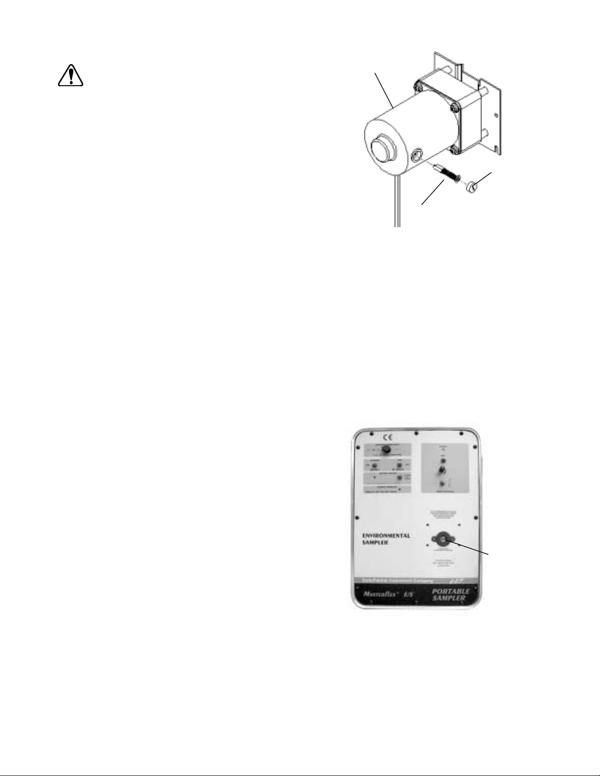
Überprüfen bzw. Auswechseln der Kohlebürsten (siehe Abbildung 3)
VORSICHT: VordemAus-undEinbau desPumpenkopfesoder
Schlauchs den Antrieb ausschalten, die Stromzu
fuhr zum Gerät (einschließlich Wechsel
strom-Gleichstromversorgung mit Umrichter,
Auto-Stromadapter oder ggf. eine andere externe
Stromquelle) unterbrechen. Den Schalter
RUN/CHARGE (BETRIEB/LADEN) für die Auswahl
der Betriebsart auf CHARGE und alle anderen
SchalteraufAUS stellen. Dadurchwirdeine verse
hentliche Aktivierung des Antriebsmechanismus
vermieden, so dass keine Finger oder losen Klei
dungsstücke in die Pumpenantriebsmechanik ge
raten können.
-
Motor
-
-
-
Kohlebürstenkappe
-
HINWEIS: Die Bürsten müssen nach jeweils 2000 Betriebsstunden oder
alle6Monate geprüft werden,oderwenn sich Fehlerinder Anwendung be
-
Kohlebürstenbaugruppe
merkbar machen.
A. Alle Schalter des Bedienfeldes auf Aus stellen und ggf. die Wech
selstrom-Gleichstromversorgung mit Umrichter lösen.
ABBILDUNG 3. AUSWECHSELN DER
KOHLEBÜRSTEN
B. Die zwölf (12) Schrauben, mit denen das Bedienfeld am Gehäuse
befestigt ist, mit einem Kreuzschlitzschraubendreher Nr. 2 lösen.
C. Das Bedienfeld vorsichtig vom Gehäuse abnehmen und die Drähte von der Batterie lösen.
D. Die Kohlebürsten mit einem Schraubendreher entfernen und die Kohlebürstenhalterung 90° entgegen dem Uhrzeigersinn
drehen. Die Kohlebürste sollte herausspringen.
E. Evtl. vorhandenen Staub von den Öffnungen der Kohlebürstenhalterung absaugen.
F. Die Kohlebürsten überprüfen. Wenn einer der Bürsten auf 4 mm oder weniger abgenutzt ist, beide Bürsten auswechseln.
G. Schritt D zum Herausnehmen der anderen Bürste wiederholen.
H.
DieBürstenwieder einsetzen,dieBatterie wiederanschließenund dasBedienfeldanbringen. DenROTENDraht andiemit +
(positiv) gekennzeichnete Anschlussklemme der Batterie anschließen, den SCHWARZEN Draht an die mit – (negativ)
gekennzeichnete Anschlussklemme der Batterie anschließen.
Auswechseln der Dichtungsmanschette für den Pumpenkopf (siehe Abbildung 4)
Jedes Gerät wird mit einer Dichtungsmanschette zum Abdichten des
Pumpenkopfes geliefert. Diese Manschette befindet sich am Bedienfeld
und umschließt die Antriebsausgangswelle. Die Dichtungsmanschette
nutzt sich im Laufe der Zeit und bei häufigem Auswechseln des Pumpen
kopfes ab. Um den IP-Schutzgrad des Geräts nicht zu beeinträchtigen,
sollte die Dichtungsmanschette bei Abnutzungserscheinungen, bei einer
Leckageodernach ein biszweiJahrenNutzung -jenachdem, was zuerst
eintritt - ausgewechselt werden.
ZumAuswechselnder DichtungsmanschettedieManschette mitderHaft
unterlage vom Bedienfeld lösen. Darauf achten, dass alle Manschetten
-
reste entfernt werden. Der Umriss der Manschette ist auf dem Bedienfeld
eingezeichnet.DenDeckfilmvonder Haftunterlage der neuen Dichtungs
manschette abziehen und die neue Manschette auf den auf dem Bedien
feld angezeigten Umriss setzen.
-
-
Dichtungsman
schette für den
Pumpenkopf
-
40
ABBILDUNG 4 DICHTUNGSMANSCHETTE FÜR
DEN PUMPENKOPF
Page 42

STÖRUNGSBEHEBUNG
1. Der An trieb lässt sich nicht über die in ter ne Strom quel le be trei ben.
A.
Si cher stel len, dass der Schal ter für die Aus wahl der Strom quel le (B) auf „BAT TE RY“ (BAT TE RIE) steht.
B.
Si cher stel len, dass der Schal ter für die Aus wahl der Be triebs art (C) auf „RUN“ (BE TRIEB) steht.
C. Si cher stel len, dass der Pum pen kopf, die Schlauch grö ße und die Schlauch zu sam men set zung d ie für die sen An trieb emp foh -
le nen Spe zi fi ka tio nen auf wei sen.
D. Bei Ver wen dung ei nes PTFE-Pumpenkopfes den Schlauch ge mäß den An lei tun gen in der Be die nung s an lei tung für den
Pum pen kopf ein le gen und star ten. Ein über mä ßi ges An zie hen des Schlauch betts kann den An triebs me cha nis mus blo ckie ren. Das Schlauch bett lang sam an zie hen, wie in der Be die nungs an lei tung für den Pum pen kop f an ge ge ben.
E.
Si cher stel len, dass der Ein-/Aus- und Wahl schal ter für die Pum pen dreh rich tung (H) je nach der ge wünsch ten Dreh rich tung ent we der auf IM UHR ZEI GER SINN (Rechts pfeil) oder auf ENT GE GEN DEM UHR ZEI GER SINN (Links pfeil) steht. Die
Strom an zei ge lam pe (K) im Be reich der An triebs be dien ele men te leuch tet.
F.
Die Bat te rie stands an zei ge (F) mit dem Bat te rie stands schal ter ak ti vie ren. Wenn die An zei ge ROT leuch tet, die Bat te ri e so fort auf la den. Die ver füg ba re Lei stung der in ter nen Bat te rie ist er schöpft.
G.
Wenn die Bat te rie stands an zei ge (F) nicht auf leuch tet, das Be dien feld ab neh men und auf lose Bat te rie an schlüs se prü fen.
H. Die Bat te rie lei stung mit ei nem di gi ta len, auf Volt Gleich strom ein ge stell ten Mul ti me ter (DMM) prü fen. Wenn die Span nung
un ter 9 V Gleich strom liegt, die Bat te rie aus wech seln.
I. Wenn kei ne der ge nann ten Lö sun gen Er folg hat, das Ge rät von Ih rem au to ri sier ten Fach hä nd ler re pa rie ren las sen.
2. Der An trieb läuft nicht mit dem von der Wech sel strom-Gleichstromversorgung mit Um rich ter ge li e fer ten ex ter nen Strom.
A.
Si cher stel len, dass der Schal ter für die Aus wahl der Strom quel le (B) auf EX TER NAL (EX TERN) steht.
B.
Si cher stel len, dass der Schal ter für die Aus wahl der Be triebs art (C) auf RUN (BE TRIEB) steht.
C. Si cher stel len, dass der Pum pen kopf, die Schlauch grö ße und die Schlauch zu sam men set zung d ie für die sen An trieb emp foh -
le nen Spe zi fi ka tio nen auf wei sen.
D. Bei Ver wen dung ei nes PTFE-Pumpenkopfes den Schlauch ge mäß den An lei tun gen in der Be die nung s an lei tung für den
Pum pen kopf ein le gen und star ten. Ein über mä ßi ges An zie hen des Schlauch betts kann den An triebs me cha nis mus blo ckie ren. Das Schlauch bett lang sam an zie hen, wie in der Be die nungs an lei tung für den Pum pen kop f an ge ge ben.
E.
Si cher stel len, dass der Ein-/Aus- und Wahl schal ter für die Pum pen dreh rich tung (H) je nach der ge wünsch ten Dreh rich tung ent we der auf IM UHR ZEI GER SINN (Rechts pfeil) oder auf ENT GE GEN DEM UHR ZEI GER SINN (Links pfeil)
steht. Die Strom an zei ge lam pe (K) im Be reich der An triebs be dien ele men te leuch tet.
F. Si cher stel len, dass der Koa xi als te cker fest im Ge rä te an schluss für die ex ter ne Strom z u fuhr (EX TER NAL PO WER IN PUT)
sitzt.
G. Si cher stel len, dass an der Wechselstromsteckdose, an der die Wech sel strom-Gleichstromversorgun g mit Um rich ter an ge -
schlos sen ist, Wech sel strom span nung an liegt.
H.
Si cher stel len, dass am 2,5 mm Koa xi al an schluss eine Gleich strom span nung von min de stens 13 V an liegt. Die Wech sel -
strom-Gleichstromversorgung mit Um rich ter ist kei ne war tungs fä hi ge Ein heit und ent hält kei ne vom Be nut zer zu
war ten den Tei le.
I. Wenn kei ne der ge nann ten Lö sun gen Er folg hat, das Ge rät von Ih rem au to ri sier ten Fach hä nd ler re pa rie ren las sen.
3. Der An trieb kann nicht über den als Zu be hör er hält li chen Au to-Stromadapter be trie ben w er den.
A.
Si cher stel len, dass der Schal ter für die Aus wahl der Strom quel le (B) auf EX TER NAL (EX TERN) steht.
B.
Si cher stel len, dass der Schal ter für die Aus wahl der Be triebs art (C) auf RUN (BE TRIEB) steht.
C. Si cher stel len, dass der Pum pen kopf, die Schlauch grö ße und die Schlauch zu sam men set zung d ie für die sen An trieb emp foh -
le nen Spe zi fi ka tio nen auf wei sen.
D. Bei Ver wen dung ei nes PTFE-Pumpenkopfes den Schlauch ge mäß den An lei tun gen in der Be die nung s an lei tung für den
Pum pen kopf ein le gen und star ten. Ein über mä ßi ges An zie hen des Schlauch betts kann den An triebs me cha nis mus blo ckie ren. Das Schlauch bett lang sam an zie hen, wie in der Be die nungs an lei tung für den Pum pen kop f an ge ge ben.
E.
Si cher stel len, dass der Ein-/Aus- und Wahl schal ter für die Pum pen dreh rich tung (H) je nach der ge wünsch ten Dreh rich tung ent we der auf IM UHR ZEI GER SINN (Rechts pfeil) oder auf ENT GE GEN DEM UHR ZEI GER SINN (Links pfeil) steht. Die
Strom an zei ge lam pe (K) im Be reich der An triebs steue run gen leuch tet.
F. Si cher stel len, dass der Koa xi als te cker des Au to-Stromadapters fest im Ge rä te an schluss f ür die ex ter ne Strom zu fuhr (EX -
TER NAL PO WER IN PUT) sitzt.
G. Si cher stel len, dass der Au to-Stromadapter fest im Zi ga ret ten an zün der des Fahr zeugs sitzt .
H. Si cher stel len, dass die Si che rung für den Zi ga ret ten an zün der nicht of fen oder durch ge brannt ist.
I. Si cher stel len, dass die Gleich strom span nung am 2,5 mm Koa xi al an schluss min de stens 12 V be trägt.
41
Page 43

J.
DiePolaritätderGleichstromspannungam 2,5 mm Anschluss prüfen.DieHülseistnegativ, die Mitte positiv.DerAntriebist
verpolsicher ausgelegt und kann bei falscher Polarität nicht in Betrieb genommen werden.
K. Wenn keine der genannten Lösungen Erfolg hat, das Gerät von Ihrem autorisierten Fachhändler reparieren lassen.
4. Die Ladeanzeige für die interne Batterie leuchtet nicht, oder die Batterie lässt sich nicht über die WechselstromGleichstromversorgung mit Umrichter aufladen.
A.
Sicherstellen, dass der Schalter CHARGE/RUN (LADEN/BETRIEB) für die Auswahl der Betriebsart (C) auf CHARGE
steht.
B. Sicherstellen,dassderKoaxialstecker der Wechselstrom-GleichstromversorgungmitUmrichterfest im Geräteanschlussfür
die externe Stromzufuhr (EXTERNAL POWER INPUT) sitzt.
C. Sicherstellen, dass an der Wechselstromsteckdose, an der die Wechselstrom-Gleichstromversorgung mit Umrichter ange
schlossenist,Wechselstromspannung anliegt. Sicherstellen,dassam 2,5 mmKoaxialanschlusseineGleichstromspannung
von mindestens 13 V anliegt.
D. Wenn keine der genannten Lösungen Erfolg hat, das Gerät von Ihrem autorisierten Fachhändler reparieren lassen.
5. Die Ladeanzeige für die interne Batterie leuchtet nicht, oder die Batterie lässt sich nicht über den Auto-Stromadapter
(Zubehör) aufladen.
A.
Sicherstellen dass der Schalter EXTERNAL/BATTERY (EXTERN/BATTERIE) für die Auswahl der Stromquelle (B) auf
EXTERNAL stellen.
B.
Sicherstellen,dassderSchalterCHARGE/RUN (LADEN/BETRIEB)für dieAuswahlder Betriebsart(C) aufRUNsteht.
C. Sicherstellen, dass der Koaxialstecker des Auto-Stromadapters fest im Antriebsanschluss für die externe Stromzufuhr
(EXTERNAL POWER INPUT) sitzt.
D. Sicherstellen, dass der Auto-Stromadapter fest im Zigarettenanzünder des Fahrzeugs sitzt.
E. Sicherstellen, dass die Sicherung für den Zigarettenanzünder nicht offen oder durchgebrannt ist.
F. Sicherstellen, dass am 2,5 mm Koaxialanschluss eine Gleichstromspannung von mindestens 13 V anliegt. Die Polarität der
Gleichstromspannung am Anschluss überprüfen.
G. DerAntriebistverpolsicher ausgelegt und kannbeifalscherPolarität nicht in Betriebgenommenwerden.Die Hülse istnega-
tiv, die Mitte positiv.
H. Wenn keine der genannten Lösungen Erfolg hat, das Gerät von Ihrem autorisierten Fachhändler reparieren lassen.
-
VOM BENUTZER AUSWECHSELBARE TEILE
77120-21 Wechselstrom-Gleichstromversorgung mit Umrichter, 115 V~
77120-26 Wechselstrom-Gleichstromversorgung mit Umrichter, 230 V~
77500-03 Ersatzsicherung für Auto-Stromadapter oder Hilfsstromversorgung
07571-55 Batterie, 12 V, 7,2 AH
07571-56 Dichtungsmanschette, Pumpenkopf (6er-Packung)
07571-57 Dichtungshülsen, Schalter und Drehzahlregler (6er-Packung)
07571-58 Knopf und Kappe, Drehzahlregler
07571-59 Ersatzkohlebürsten-Kitt, jeweils 2
07571-60 Wechselstrom-Gleichstromversorgung mit Umrichter, 100 V~ (Japan)
42
Page 44

ZUBEHÖR
06456-10 Schlauchverbinder, 3/16 Zoll (für Schlauchgrößen L/S®15 und L/S®25), Schlaucholive
®
06456-20 Schlauchverbinder, 1/4 Zoll (für Schlauchgröße L/S
07570-04 Durchflussgewicht Schlauch, für Schlauchgrößen L/S
24), Schlaucholive
®
15, 24 oder 25)
07571-50 Auto-Stromadapter, strombegrenzt
07571-52 Hilfsstromversorgung mit Ladegerät, 115 V~
07571-54 Hilfsstromversorgung mit Ladegerät, 230 V~
TECHNISCHE DATEN
Betriebsdrehzahl: 70 bis 400 U/min
Betriebsspannung/-frequenz:
Modell 07571-00 115 V~ nominal 50/60 Hz (100 – 130) V~ bei 120 mA ~
Modell 07571-05 230 V~ nominal 50/60 Hz (200 – 260) V~ bei 60 mA ~
Anzahl Pumpenköpfe: 1
Drehmomentlast: 0,35 N•m max.
Drehrichtung: Im Uhrzeigersinn und entgegen dem Uhrzeigersinn
Betriebstemperatur: 0 bis 50 °C
Lagertemperatur: –20 bis 65 °C
Luftfeuchtigkeit (nicht kondensierend): 10 bis 90 %
Höhe: 2000 m
Abmessungen (L ⫻ B ⫻H): 27,94 ⫻ 26,04 ⫻40,64 cm
Gewicht: 7,49 kg
Chemische Beständigkeit: Polyethylen von hoher Dichte, klar eloxiertes Aluminium,
Gehäuseschutzart: IP 54 gemäß IEC 529
Umweltverschmutzungsgrad: Grad 2 nach IEC 664
Einbaukategorie: Kategorie II gemäß IEC 664 (Lokale Haushaltsgeräte, tragbare
Entspricht den Normen:
07571-00 Die 115 V~Wechselstrom-Gleichstromversorgung mit Umrichter
07571-05 230 V (für CE-Kennzeichen):
12 V Gleichstrom nominal (11 – 16) V Gleichstrom bei 2,4 A
Gleichstrom
12 V Gleichstrom nominal (11 – 16) V Gleichstrom bei 2,4 A
Gleichstrom
rostfreier Stahl und Polyester. Alle Materialien sind gegen
Standardlösungsmittel beständig.
Geräte usw.)
hat die UL- und CSA-Zulassung. Aufgrund der niedrigen
Spannung sind die Spezifikationen der Aufsichsbehörden
auf das restliche Gerät nicht anwendbar.
EMV-Richtlinie der EU
(EN61326-1/A1:1998)
43
Page 45

GARANTIE
Um optimale Anwendungsergebnisse zu gewährleisten, sind für MASTERFLEX-Pumpen ausschließlich MASTER
FLEX-Präzisionsschläuche zu verwenden. Der Einsatz anderer Schläuche kann eine Verweigerung der Garantieleistung
nach sich ziehen.
Der Hersteller garantiert, dass dieses Produkt keine nennenswerten Abweichungen von den veröffentlichten Spezifikationen auf
weist.FallswährendderGarantiezeit eine Reparatur oder Nachbesserungerforderlichwerdensollte,wird dies kostenlos vorgenom
men, vorausgesetzt, es liegt kein vom Hersteller feststellbarer fehlerhafter oder unsachgemäßer Einsatz seitens des Kunden vor.
Reparaturkosten außerhalb der Garantiezeit oder aufgrund von fehlerhaftem oder unsachgemäßem Gebrauch des Produktes wer
den Ihnen in Rechnung gestellt.
Die Garantiefrist für dieses Produkt ist auf der Garantiekarte vermerkt.
WARENRÜCKSENDUNGEN
Um KostenundVerzögerungensogeringwiemöglich zu halten, lassen Sie sich in jedemFallvonIhremFachhändleroderdem Her
steller eine Rücksendegenehmigung und die Versandanweisungen geben, bevor Sie Ware zurückschicken. Geben Sie bitte den
Rücksendegrund mit an. Verpacken Sie die Ware sorgfältig und versichern Sie die Sendung gegen Beschädigung bzw. Verlust. Für
Transportschäden aufgrund unsachgemäßer Verpackung haften Sie.
TECHNISCHE HILFE
WennSieFragenzurAnwendung dieseProduktes haben,wendenSiesichbitte andenHerstelleroderautorisierten Fachhändler.
-
-
-
-
-
Cole-Parmer Instrument Company
625 East Bunker Court
Vernon Hills, Illinois U.S.A. 60061-1844
1-800-MASTERFLEX (627-8373) (U.S. and Canada only)
11 (847) 549-7600 (outside U.S.)
(847) 549-7600 (Local)
FAX (847) 247-2929 (U.S. and Canada only)
11 (847) 549-1700 (Fax outside U.S.)
www.masterflex.com
e-mail: techinfo@coleparmer.com
Barnant Company
28W092 Commercial Ave.
Barrington, Illinois U.S.A. 60010-2392
1-800-637-3739 (U.S. and Canada only)
11 (847) 381-7050 (outside U.S.)
(847) 381-7050 (Local)
11 (847) 381-7053 (Fax outside U.S.)
(847) 381-7053 (Local Fax)
www.barnant.com
e-mail: barnant@barnant.com
44
Printed in U.S.A.
040601
Page 46

ANHANG A
EMPFEHLUNGEN FÜR PUMPENKÖPFE, SCHLAUCHGRÖSSEN, SCHLAUCHZUSAMMENSETZUNGEN UND MODELLNUMMERN
SCHLAUCHMODELLNUMMERN
PUMPENKOPF,
TYP L/S
®
PUMPEN-
MODELLNR.
Standard 07013-20
07013-21
SCHLAUCH-
GRÖSSE
13 96400-13
SILICON C-FLEX
06424-13 06409-13 06429-13 06485-13 06404-13 06412-13
96410-13
®
TYGON
LAB
®
07013-52
07014-20
07014-21
14 96400-14
96410-14
06424-14 06409-14 06429-14 06485-14 06404-14 06412-14
07014-52
07015-20
07015-21
15 96400-15
96410-15
06424-15 06409-15
07015-52
07016-20
07016-21
16 96400-16
96410-16
06424-16 06409-16 06429-16 06485-16 06404-16
07016-52
07024-20
07024-21
24 96400-24
96410-24
06424-24
07024-52
QUICK
LOAD
®
07021-22
07021-26
15 96400-15
96410-15
24 96400-24
06424-15 06409-15
06424-24
96410-24
13 96400-13
06424-13 06409-13 06429-13 06485-13 06404-13 06412-13
96410-13
07021-20
07021-24
14 96400-14
96410-14
16 96400-16
06424-14 06409-14 06429-14 06485-14 06404-14 06412-14
06424-16 06409-16 06429-16 06485-16 06404-16
96410-16
EASY-LOAD
®
07518-02
07518-12
07518-62
25 96400-25
96410-25
15 96400-15
96410-15
24 96400-24
96410-24
13 96400-13
06424-25 06409-25 06429-25
06424-15 06409-15
06424-24 06409-24 06429-24
06424-13 06409-13 06429-13 06485-13 06404-13 06412-13
96410-13
07518-00
07518-10
07518-60
14 96400-14
96410-14
16 96400-16
96410-16
25 96400-25
06424-14 06409-14 06429-14 06485-14 06404-14 06412-14
06424-16 06409-16 06429-16 06485-16 06404-16
06424-25 06409-25 06429-25 06485-25 06404-25
96410-25
PTFE 77390-00 4mm 77390-50
PTFE 77390-00 6mm 77390-60
TYGON
LFL
®
PHARMED
®
NORPRENE
VITON
®
Fluorelastomer
®
PTFE
Anmerkung: Das Präfix 96400 kennzeichnet mit Peroxid vulkanisierte Siliconschläuche.
Das Präfix 96410 kennzeichnet mit Platin vulkanisierte Siliconschläuche.
45
Page 47

ANHANG B
HUB IM VERHÄLTNIS ZU SCHLAUCHGRÖSSE, ZUSAMMENSETZUNG UND DURCHFLUSS
ALLE DURCHFLUSSRATEN SIND IN ml/min BEI 21,1 °C ANGEGEBEN
HUB IN
m
SCHLAUCHGRÖSSE
0
3,66 m 635 690 710
15
SILICON
C-FLEX
675 740 740
TYGON
LAB
®
7,62 m 290 210 570
0
3,66 m 730 955 1030
24
1085 1060 1040
7,62 m Max. Hub 4,57 m 560 670
0
3,66 m 260 625 680 690
25
750 825 785 740
7,62 m Max. Hub 4,57 m 130 365 345
0
3,66 m 29
4 mm
7,62 m 20
0
3,66 m 31
6 mm
7,62 m 19
Anmerkungen: 1. Die oben angegebenen Durchflussraten wurden auf einer EASY-LOAD-Pumpe erzeugt.
2. Der durchschnittliche barometrische Druck beträgt 740 mm Hg.
3. Bei den genannten Durchflussraten handelt es sich um Nenn- oder Durchschnittswerte.
4. Die Pumpe mit PTFE-Schlauch wird mit 400 U/min betrieben, was über der empfohlenen Drehzahl liegt; dies gilt nur für
intermittierenden Gebrauch (10 – 15 Minuten) und führt zu einer verkürzten Schlauchlebensdauer. Bei Dauereinsatz 300 U/min nicht
überschreiten. Für den Einsatz mit 300 U/min die Durchflussraten um 33 % reduzieren.
TYGON
LFL
®
NORPRENE
®
PHARMED
PTFE
30
84
46
Page 48

ÍNDICE
Título Página
PRECAUCIONES DE SEGURIDAD. . . . . . . . . . . . . . . . . . . . . . . . . . . . . . . . . . . . . . . . . . . . . . . . . . . . . . . . . . . . . . . . . 48
INTRODUCCIÓN Y DESCRIPCIÓN GENERAL. . . . . . . . . . . . . . . . . . . . . . . . . . . . . . . . . . . . . . . . . . . . . . . . . . . . . . . . 49
ELEVACIÓN POR ASPIRACIÓN . . . . . . . . . . . . . . . . . . . . . . . . . . . . . . . . . . . . . . . . . . . . . . . . . . . . . . . . . . . . . . . . . . . 49
CONFIGURACIÓN . . . . . . . . . . . . . . . . . . . . . . . . . . . . . . . . . . . . . . . . . . . . . . . . . . . . . . . . . . . . . . . . . . . . . . . . . . . . . . 49
CONTROLES Y FUNCIONES . . . . . . . . . . . . . . . . . . . . . . . . . . . . . . . . . . . . . . . . . . . . . . . . . . . . . . . . . . . . . . . . . . . . . 50
FUNCIONAMIENTO DEL PROPULSOR . . . . . . . . . . . . . . . . . . . . . . . . . . . . . . . . . . . . . . . . . . . . . . . . . . . . . . . . . . . . . 51
1. Selección del modo de operación . . . . . . . . . . . . . . . . . . . . . . . . . . . . . . . . . . . . . . . . . . . . . . . . . . . . 51
2. Instrucciones para la operación. . . . . . . . . . . . . . . . . . . . . . . . . . . . . . . . . . . . . . . . . . . . . . . . . . . . . . 51
MANTENIMIENTO . . . . . . . . . . . . . . . . . . . . . . . . . . . . . . . . . . . . . . . . . . . . . . . . . . . . . . . . . . . . . . . . . . . . . . . . . . . . . . 53
LOCALIZACIÓN DE AVERÍAS . . . . . . . . . . . . . . . . . . . . . . . . . . . . . . . . . . . . . . . . . . . . . . . . . . . . . . . . . . . . . . . . . . . . . 56
PIEZAS DE REPUESTO DEL USUARIO . . . . . . . . . . . . . . . . . . . . . . . . . . . . . . . . . . . . . . . . . . . . . . . . . . . . . . . . . . . . . 57
ACCESORIOS . . . . . . . . . . . . . . . . . . . . . . . . . . . . . . . . . . . . . . . . . . . . . . . . . . . . . . . . . . . . . . . . . . . . . . . . . . . . . . . . . 58
ESPECIFICACIONES. . . . . . . . . . . . . . . . . . . . . . . . . . . . . . . . . . . . . . . . . . . . . . . . . . . . . . . . . . . . . . . . . . . . . . . . . . . . 58
GARANTÍA . . . . . . . . . . . . . . . . . . . . . . . . . . . . . . . . . . . . . . . . . . . . . . . . . . . . . . . . . . . . . . . . . . . . . . . . . . . . . . . . . . . . 59
DEVOLUCIÓN DE PRODUCTOS. . . . . . . . . . . . . . . . . . . . . . . . . . . . . . . . . . . . . . . . . . . . . . . . . . . . . . . . . . . . . . . . . . . 59
ASISTENCIA TÉCNICA . . . . . . . . . . . . . . . . . . . . . . . . . . . . . . . . . . . . . . . . . . . . . . . . . . . . . . . . . . . . . . . . . . . . . . . . . . 59
APÉNDICE A. . . . . . . . . . . . . . . . . . . . . . . . . . . . . . . . . . . . . . . . . . . . . . . . . . . . . . . . . . . . . . . . . . . . . . . . . . . . . . . . . . . 60
APÉNDICE B. . . . . . . . . . . . . . . . . . . . . . . . . . . . . . . . . . . . . . . . . . . . . . . . . . . . . . . . . . . . . . . . . . . . . . . . . . . . . . . . . . . 61
C-FLEX es marca comercial registrada de Consolidated Polymer Technologies, Inc.
NORPRENE, PHARMED, TYGON son marcas comerciales registradas de Norton Co.
VITON es marca comercial registrada de DuPont Dow Elastomers L.L.C.
Las marcas comerciales registradas con el símbolo ® en esta publicación están registradas en los EE.UU. y otros países.
ESPAÑOL
47
Page 49
PRECAUCIONES DE SEGURIDAD
PELIGROS: NUNCA aplique tensionesdecorrientealternadirectamentealreceptáculodeENTRADA DE POTENCIA
EXTERIOR del tablero frontal. La aplicación de estas tensiones podría causar lesiones personales o la
muerte del operarioyladestruccióndelequipo.Utilice solamente el convertidor de CA/CC provisto con
la unidad para proporcionar potencia al equipo desde una fuente de corriente alterna.
NUNCApongaencortocircuito ni conectejuntoslos bornes de labatería.Un cortocircuito delosbornes
de labateríacausaríacalentamientointernorápido de la misma, provocando la explosión delabateríay
lesiones graves o la muerte del operario.
ElConvertidor/Alimentadorde CA/CCestádiseñado paraUSOEN EL INTERIORSOLAMENTE.NO
enambientesexteriores paracargarla bateríaosuministrar potencia alpropulsor. De ignorarseesteavi
so, se podrían causar sacudidas eléctricas, lesiones graves e incluso la muerte.
NO QUEME NI INCINERE LA BATERÍA. ÉSTA PODRÍA EXPLOTAR CAUSANDO LESIONES GRAVES O
LA MUERTE AL PERSONAL CERCANO. (Recicle la batería agotada.)
PRECAUCIONES: No invierta las conexiones a la batería. Si se invierten estas conexiones, se causarán averías en el
equipo.
Cargue totalmente el equipo antes de utilizarlo por primera vez. Si trata de hacer funcionar el equipo
mientras la batería está totalmente descargada, se producirán daños a la batería interna.
La inmersión del equipo causará un funcionamiento inadecuado y posiblemente, daños al equipo.
El uso de cabezales de bomba, tamaños de tubos y formulaciones diferentes de los especificados en
este manual, o el montaje y utilización de dos o más bombas simultáneamente, causará un funciona
miento inadecuado y posibles daños al equipo.
ADVERTENCIAS: Larotura de lostubospuedecausar que labombarocíelíquido. Utilice lasmedidasadecuadaspara pro
teger al operario y al equipo.
Apague el propulsor, desconecte toda la corriente eléctrica al equipo, incluyendo el convertidor de
CA/CC, el adaptador de potencia automotriz o cualquier otra alimentación externa de potencia, si la hubiere, antes de quitar o instalar uncabezaldebombaotubos.ColoqueelinterruptordeMododeOperación (RUN/CHARGE)enlaposición “CHARGE” y todos losdemásinterruptoresen posición “apagado”.
Esto ayudará a prevenir la activación involuntaria del mecanismo propulsor, evitando que los dedos o
las ropas flojas queden enganchadas en el mecanismo impulsor de la bomba.
louse
-
-
-
ADVERTENCIA: LIMITACIÓN DEL USO DEL PRODUCTO
Este producto no está diseñado ni tiene como fin ser utilizado en aplicaciones conectadas a pacientes; incluidas aplicaciones
médicasydentales,pero sinlimitarsealas mismas, ydeacuerdocon estonoseha enviado ladocumentaciónparasu aproba
ción por la FDA.
48
-
Page 50

INTRODUCCIÓN Y DESCRIPCIÓN GENERAL
El Propulsor de Bomba MASTERFLEX®E/S™ (Muestreo Ambiental) provee velocidades de bombeo de 70 a 400 rpm en dirección
hacia la derecha o hacia la izquierda, para purgar tubos y para muestreo de líquidos.
Elpropulsoryel sistema decargatienenlimitador de sobreintensidad,yestánprotegidos contra polaridad inversadelaalimentación
de corriente y contra voltajes transitorios.
Se puede hacer funcionar el propulsor con la batería interna, con una alimentación de corriente continua externa de 12 V o con co
rrientealternaexternade115 Vo 230V,cuandoseutiliza conelconvertidordecorriente alternay continuaprovistoconelequipo.
Elpropulsortiene una bateríaprotegidacontra salpicadurasyunsistema derecargaintegrados, por loquese puedecargarelequipo
desdeunaalimentación deCAutilizando el convertidordecorriente, odesdeun sistemaeléctricoautomotriz de corrientecontinuade
12 V, si se utiliza con el accesorio Adaptador de Potencia Automotriz.
Estádiseñadoparaaceptaryactivar un cabezal de bomba contuboMASTERFLEX
®
L/S®Standard,QUICKLOAD®,EASY-LOAD®o
PTFE para transferencia de líquidos y muestreo en el campo.
Elequipoestá albergadoenunacajaprotectoradealtavisibilidad. Eltablerode controlylos controlesdelpropulsor tienenlaclasifica
ción de protección IP54 solamente cuando hay una Cabezal de bomba montado en el propulsor.
Cuandoestácerrado, elpropulsorflotará durante30minutos comomínimosecayese aunlago ounacorriente deagua,para permitir
recuperarlo.
ELEVACIÓN POR ASPIRACIÓN
La combinación del propulsor MASTERFLEX®E/S™ y una Cabezal de bomba MASTERFLEX puede elevar una muestra de agua
hasta7,9m verticalmente.Estacapacidad sellamaelevación poraspiracióny semidedesde lasuperficiedel líquidohastael cabezal
de bomba.
Cuandoellíquido del quesetoman muestras tieneunaviscosidad odensidadmayorque ladelagua,esta capacidaddeelevación se
reduce.
-
-
CONFIGURACIÓN
1. El propulsor ha sido embalado cuidadosamente para protegerlo durante el tránsito desde la fábrica hasta su destino final. Una
vez abierta la caja de cartón, guarde el material de embalaje hasta haber verificado que el producto funciona correctamente.
El propulsor consta de lo siguiente:
(1) Equipo propulsor
(1) Convertidor/alimentador de corriente alterna y corriente continua (CA/CC)
(2) Llaves para los cerrojos de seguro
(1) Manual de operación
(1) Tarjeta de garantía
(1) Bolsa para accesorios
PRECAUCIÓN: El uso de cabezales de bomba, tamaños de tubos y formulaciones diferentes de los especificados en
este manual, o el montaje y utilización de dos o más bombas simultáneamente, causará un funciona
miento inadecuado y posibles daños al equipo.
ADVERTENCIA: Apague el propulsor, desconecte toda la corriente eléctrica al equipo, incluyendo el convertidor de
CA/CC, el adaptador de potencia automotriz o cualquier otra alimentación externa de potencia, si la hu
biere, antes de quitar o instalar el cabezal de bomba o tubos. Coloque el interruptor de Modo de Opera
ción (RUN/CHARGE) en la posición “CHARGE” y todos los demás interruptores en posición apagado.
Esto ayudará a prevenir la activación involuntaria del mecanismo propulsor, de modo que los dedos o
las ropas flojas no queden enganchadas en el mecanismo impulsor de la bomba.
2. El propulsor noincluyenicabezaldebomba ni tubos. El propulsorpuedehacerfuncionaruno (1) de las siguientescabezalesde
bomba: MASTERFLEX
En el Apéndice A hallará los números de catálogo de los cabezales de bomba y tubos recomendados.
En el Apéndice B hallará los caudales y la elevación.
®
L/S®Standard, L/S QUICK LOAD, L/S EASY-LOAD o L/S PTFE.
-
-
-
49
Page 51
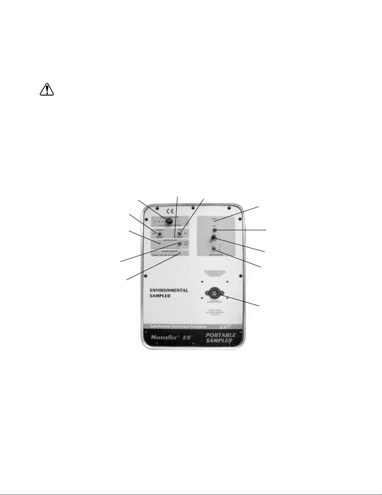
Seleccioneunode los cabezalesdebombay formulacionesdetubosMASTERFLEX recomendados ymóntelosen el propulsor,
siguiendo las instrucciones del manual del Cabezal de bomba.
NOTA: RENDIMIENTO ÓPTIMO EN EL ARRANQUE
El propulsor está sometido a la carga mayor cuando arranca con un tubo nuevo. Para lograr el rendimiento óptimo con un tubo
nuevo,enciendaelmecanismo propulsor yactiveel interruptor “MAX”durante30segundos. Después, suelteelinterruptorMAX
y ajuste la velocidad de la bomba, utilizando el mando de control de velocidad.
Para obtener el óptimo rendimiento y facilidad de uso, se recomiendan los cabezales de bomba EASY-LOAD o PTFE.
ADVERTENCIA: La rotura delostubospuede causar quelabombarocíe líquido. Utilicelasmedidasadecuadas para pro
teger al operario y al equipo.
CONTROLES Y FUNCIONES
Los controles están divididos en dos secciones.
Loscontrolesenelladoizquierdo del tablero de controlcontrolanlapotenciayel modo de operación, paraseleccionarobienfuncio
namiento del propulsor o carga de la batería interna.
Los controlesenelladoderechodel tablero de control son para controlar elmecanismopropulsor,porejemplodireccióny velocidad
de propulsión.
Los controles del propulsor solo funcionan después de hacer las selecciones apropiadas en la sección de controles del lado
izquierdo.
D— Luz del indicador
A— Entrada de la potencia exterior
B— Interruptor selector de
alimentación de potencia
de carga
C—Interruptor selector de modo de operación
K—Indicador de potencia del propulsor
-
-
F— Indicador de situación de la batería
E— Interruptor activador de
situación de la batería
G— Indicador de enclavamiento de carga
J— Máximo
I— Control de velocidad
H— Interruptor selector de la dirección de
rotación de la bomba y para Encender/Apagar
Junta de sello del cabezal de bomba
FIGURA 1 TABLERO DE CONTROL
A. ENTRADA DE POTENCIA EXTERIOR
Receptáculocoaxialde2,5mmpara alimentar corriente continua al propulsor,paracargarlabatería interna o hacer funcionar el
propulsor con una alimentación de potencia diferente de la batería interna. La clavija central es positiva (+), el manguito es
negativo (–).
B. INTERRUPTOR SELECTOR DE ALIMENTACIÓN DE POTENCIA
Selecciona si el operario utilizará la batería interna (BATTERY) o una alimentación de potencia exterior (EXTERNAL) para
impulsar el mecanismo propulsor.
C. INTERRUPTOR SELECTOR DEL MODO DE OPERACIÓN
Selecciona si el operador hará funcionar (RUN) la bomba o cargará (CHARGE) la batería.
Nota: Labateríanopuedecargarsemientraslabombaestá funcionando. Se puede escoger una de las dos cosas, pero no
ambas. Cuando está en la posición CHARGE, todas las demás funciones quedan desactivadas.
50
Page 52

D. LUZ DEL INDICADOR DE CARGA
Un LED verde que se ilumina cuando se ha aplicado potencia exterior y el equipo está en el modo de operación de carga de la
batería.
E. INTERRUPTOR ACTIVADOR DE SITUACIÓN DE LA BATERÍA
Activa el indicador de situación de la batería, moviéndolo hacia arriba o hacia abajo y sujetándolo.
F. INDICADOR DE SITUACIÓN DE LA BATERÍA
Se ilumina de tres modos diferentes para indicar el potencial de la batería.
Verde, continuo = La batería está totalmente cargada
Verde, destellando = La batería está parcialmente descargada, queda 50% o menos de su capacidad
Rojo = La batería está totalmente descargada, cargarla inmediatamente
G. INDICADOR DE ENCLAVAMIENTO DE CARGA
Seiluminacuandolatemperatura ambientedelacajaes demasiadoalto paracargarla bateríasin riesgo.Cuandoestáiluminado,
el circuito de carga se ha desactivado. El sistema puede funcionar, pero no se puede cargar.
H. INTERRUPTOR SELECTOR DE DIRECCIÓN DE ROTACIÓN DE LA BOMBA Y ENCENDER/APAGAR
Esteinterruptorenciende yapagala bomba(ONy OFF)ypermite alusuarioescoger ladirecciónderotacióndelabomba:alade
recha o la izquierda. En la posición central, se apaga.
I. CONTROL DE VELOCIDAD
Elpotenciómetrodeuna (1) vuelta controla lavelocidaddela bomba. Girando aladerecha,aumenta la velocidad; alaizquierda,
la reduce.
J. MÁXIMO
Un interruptor que efectúa una derivación de los circuitos de control de velocidad para hacer que la bomba funcione a su veloci
dadnominalmáxima.Se puede usar paracebaropurgarlos tubos, dependiendo delaposicióndel Interruptor de seleccióndela
dirección de giro (H).
K. INDICADOR DE POTENCIA DEL PROPULSOR
Un LED verde que se ilumina cuando el Interruptor de selección de dirección de giro (ON/OFF) está en una posición distinta de
OFF. Esto indica que el mecanismo propulsor está activado.
-
-
FUNCIONAMIENTO DEL PROPULSOR
1. Selección del modo de operación
El equipo puede funcionar en tres modos diferentes:
A. Cargar la batería interna. Esto desactiva todas las otras funciones.
B. Operar el propulsor con alimentación de potencia de la batería interna.
C. Operar el propulsor con una alimentación de potencia exterior.
2. Instrucciones para el funcionamiento
Para cargar la batería interna con el convertidor de corriente CA/CC u otra Alimentación de potencia exterior:
PRECAUCIÓN: Cargue totalmente el equipo antes de utilizarlo por primera vez. Si trata de hacer funcionar el equipo
mientras la batería está totalmente descargada, se producirán daños a la batería interna.
A.
Conecte el convertidor de corriente CA/CC provisto al propulsor levantando la tapa del receptáculo de ENTRADA DE
POTENCIA EXTERIOR (A) e introduciendo la clavija coaxial de corriente de 2,5 mm en el receptáculo. (Vea la Figura 1.)
PELIGRO: NUNCA aplique tensiones de corriente alterna directamente al receptáculo de ENTRADA DEPOTENCIA
EXTERIOR del tablero frontal. La aplicación de estas tensiones podría causar lesiones personales o la
muerte del operario y la destrucción del equipo. Utilice solamente el convertidor/alimentador de CA/CC
provisto con la unidad para proporcionar potencia al equipo desde una fuente de corriente alterna.
B.
Conecteelconvertidor/alimentador de corrienteCA/CCa unaalimentaciónde corriente alterna.Pongael Interruptor
selector de alimentación de potencia (B), (EXTERNAL/BATTERY) en posición “BATTERY”.
C.
Ponga el interruptor selector del modo de operación (C), (RUN/CHARGE) en posición “CHARGE”.
D.
El indicador CHARGE se iluminará.
E.
Cargue la batería durante 8–12 horas.
51
Page 53

Para hacer funcionar la bomba con la batería interna
PELIGRO: El Convertidor/AlimentadordeCA/CC está diseñadoparaUSO ENELINTERIOR SOLAMENTE.NOlo use
enambientesexteriores paracargarla bateríaosuministrar potencia alpropulsor. De ignorarseesteavi
so, se podrían causar sacudidas eléctricas, lesiones graves e incluso la muerte.
PRECAUCIÓN: Cargue totalmente el equipo antes de utilizarlo por primera vez. Si trata de hacer funcionar el equipo
mientras la batería está totalmente descargada, se producirán daños a la batería interna.
A.
Ponga el interruptor selector de alimentación de potencia (B), (EXTERNAL/BATTERY) en la posición “BATTERY”.
B.
Ponga el interruptor selector del modo de operación (C), (RUN/CHARGE) en la posición “RUN”.
C.
Haga una selección en el Interruptor selector de dirección de rotación On/Off (H), DER o IZQ. (Vea la Figura 1.) (Para
cambiar la dirección, primero desconecte la potencia poniendo este interruptor en la posición central [OFF]).
D.
Ajusteelcaudal delabomba conelControlde velocidad(I)de unavuelta,girando laperillaala derechaparaaumentar el
caudal, o a la izquierda para reducirlo.
E.
Para“Cebareltubo”, muevaelInterruptor“MAX” (J), haciaarribao hacia abajo,paraquela bombafuncioneala máxima
velocidad.
Para comprobar el potencial disponible de la batería
AVISO: Para mayor precisión, compruebe la batería interna con la bomba en funcionamiento.
A.
Ponga el interruptor selector de alimentación de potencia (B), (EXTERNAL/BATTERY) en la posición “BATTERY”.
B.
Ponga el interruptor selector de modo de operación (C), (RUN/CHARGE) en la posición “RUN”.
C.
Haga una selección en el Interruptor selector de dirección de rotación On/Off (H), DER o IZQ. (Vea la Figura 1.) (Para
cambiar la dirección, primero desconecte la potencia poniendo este interruptor en la posición central [OFF]).
D.
Muevaelinterruptordesituación dela bateríahaciaarribaohacia abajoysujételo.Elindicador desituación seiluminará.
Verde, continuo = La batería está totalmente cargada
Verde, destellando = La batería está parcialmente descargada, queda 50% o menos de su capacidad
Rojo = La batería está totalmente descargada, cargarla inmediatamente
-
Para hacer funcionar la bomba con una batería externa de 12V, el adaptador de potencia automotriz u otra alimentación
de corriente continua.
PELIGRO: El Convertidor/AlimentadordeCA/CC está diseñadoparaUSO ENELINTERIOR SOLAMENTE.NOlo use
enambientesexteriores paracargarla bateríaosuministrar potencia alpropulsor. De ignorarseesteaviso, se podrían causar sacudidas eléctricas, lesiones graves e incluso la muerte.
PRECAUCIÓN: Cargue totalmente el equipo antes de utilizarlo por primera vez. Si trata de hacer funcionar el equipo
mientras la batería está totalmente descargada, se producirán daños a la batería interna.
A.
Pongaelinterruptorselectorde alimentaciónde potencia(B),(EXTERNAL/BATTERY) enla posición“EXTERNAL”.
B.
Ponga el interruptor selector del modo de operación (C), (RUN/CHARGE) en la posición “RUN”.
C.
Haga una selección en el Interruptor selector de dirección de rotación On/Off (H), DER o IZQ. (Vea la Figura 1.) (Para
cambiar la dirección, primero desconecte la potencia poniendo este interruptor en la posición central [OFF]).
D.
Ajusteelcaudal delabomba conelControlde velocidad(I)de unavuelta,girando laperillaala derechaparaaumentar el
caudal, o a la izquierda para reducirlo.
E.
Para“Cebareltubo”, muevaelInterruptor“MAX” (J), haciaarribao hacia abajo,paraquela bombafuncioneala máxima
velocidad.
52
Page 54

Para hacer funcionar la bomba con una alimentación de potencia de corriente alterna
PELIGRO: NUNCA aplique tensiones de corriente alterna directamente al receptáculo de ENTRADA DEPOTENCIA
EXTERIOR del tablero frontal. La aplicación de estas tensiones podría causar lesiones personales o la
muerte del operarioyladestruccióndelequipo.Utilice solamente el convertidor de CA/CC provisto con
la unidad para proporcionar potencia al equipo desde una fuente de corriente alterna
PELIGRO: El Convertidor/AlimentadordeCA/CC está diseñadoparaUSO ENELINTERIOR SOLAMENTE.NO
louse
en ambientes exteriores para cargar la batería o suministrar potencia al propulsor. De ignorarse este
aviso, se podrían causar sacudidas eléctricas, lesiones graves e incluso la muerte.
A.
Conecte el convertidor de corriente CA/CC provisto al propulsor levantando la tapa del receptáculo ENTRADA DE
POTENCIA EXTERIOR (A) e introduciendo la clavija coaxial de corriente de 2,5 mm en el receptáculo. (Vea la Figura 1.)
B.
Conecte el convertidor/alimentador de corriente CA/CC a una alimentación de corriente alterna. Ponga el selector
de alimentación de potencia interruptor (B), (EXTERNAL/BATTERY) en la posición “EXTERNAL”.
C.
Ponga el interruptor selector del modo de operación (C), (RUN/CHARGE) en la posición “RUN”.
D.
Haga una selección en el Interruptor selector de dirección de rotación On/Off (H), DER o IZQ. (Vea la Figura 1.) (Para
cambiar la dirección, primero desconecte la potencia poniendo este interruptor en la posición central [OFF]).
E.
Ajusteelcaudal delabomba conelControlde velocidad(I)de unavuelta,girando laperillaala derechaparaaumentar el
caudal, o a la izquierda para reducirlo.
F.
Para “Cebar el tubo”, mueva el Interruptor “MAX” (J), hacia arriba o hacia abajo y sujételo en esa posición, para que la
bomba funcione a la máxima velocidad.
MANTENIMIENTO
PRECAUCIÓN: La inmersión del equipo causará un funcionamiento inadecuado y posiblemente, daños al equipo.
Limpieza
Limpielassuperficies exterioreseinterioresde lacajay del tablerodecontrol conuntraposeco ohumedecidocon detergentesuave.
Nunca sumerja el equipo ni utilice exceso de líquido.
Batería interna
Labateríainterna estáfabricadaapruebade derramesysellada, notienepartes internasnielementos queelusuario puedareparary
con el mantenimiento adecuado, proporcionará años de servicio útil.
PRECAUCIÓN: Cargue totalmente el equipo antes de utilizarlo por primera vez. Si trata de hacer funcionar el equipo
mientras la batería está totalmente descargada, se producirán daños a la batería interna.
A. Cargue totalmente el equipo antes de utilizarlo por primera vez.
B. Guarde el equipo a temperatura ambiente, si es posible.
C. Guarde siempre el equipo completamente cargado.
D. La batería se descargará por si sola con el tiempo. La velocidad dedescargaaumentaconlatemperatura.Recomendamos
hacer funcionar elequipoalmenos2horascadaseismesesyluego, recargarlo durante la noche. Así se conservará la vida
potencial de la batería interna al máximo.
E. No deje el equipo cargándose durante más de 24 horas. La carga prolongada innecesaria causará calentamiento interno y,
potencialmente,falloprematuro delabatería.Labatería completamentedescargadase cargarádeltodo en8–12horas.Una
vez quelabateríahaalcanzadosu carga completa, el circuito cargador/regulador de labateríainternalapondráen el modo
de carga lenta, para impedir la sobrecarga.
Para cargar la batería interna desde una alimentación de corriente alterna
PELIGRO: NUNCA aplique tensiones de corriente alterna directamente al receptáculo de ENTRADA DEPOTENCIA
EXTERIOR del tablero frontal. La aplicación de estas tensiones podría causar lesiones personales o la
muerte del operarioyladestruccióndelequipo.Utilice solamente el convertidor de CA/CC provisto con
la unidad para proporcionar potencia al equipo desde una fuente de corriente alterna.
53
Page 55
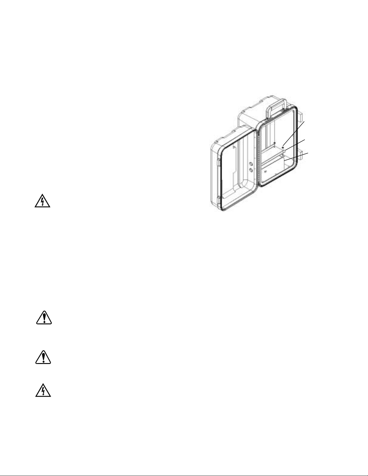
A.
Conecteelconvertidorde corriente CA/CC provistoalpropulsor levantando latapadelreceptáculo ENTRADA DE PO
TENCIA EXTERIOR (A) e introduciendo la clavija coaxial de corriente de 2,5 mm en el receptáculo. (Vea la Figura 1.)
B.
Conecte el convertidor/alimentador de corriente CA/CC a una alimentación de corriente alterna.
C.
Ponga el interruptor selector del modo de operación (C), (RUN/CHARGE) en la posición “CHARGE”.
D. El indicador de carga se iluminará cuando el circuito de carga esté activado.
E. La batería totalmente descargada se cargará completamente en 8–12 horas.
-
Para cargar la batería interna con una batería externa de 12V, el adaptador de potencia automotriz 07571-50 u otra ali
-
mentación de corriente continua
A.
Conecte la alimentación de potencia exterior levantando la
tapadelreceptáculo ENTRADADEPOTENCIA EXTERIOR
(A) e introduciendo la clavija coaxial de corriente de 2,5 mm
en el receptáculo. (Vea la Figura 1.)
B. Conecte el accesorio adaptador de potencia automotriz
07571-50 al encendedor de cigarrillos del vehículo.
C.
Pongaelinterruptor selectordelmodo de operación(C),
(CHARGE/RUN) en la posición “CHARGE”.
D. El indicador de carga se iluminará cuando el circuito de car
ga esté activado.
E. La batería totalmente descargada se cargará del todo en
8–12 horas.
-
Tuerca
#6-32 SEMS
4 lugares
Soporte—Barra
de contención
de sujeción de
la batería
Batería:
Observe la
posición de
los bornes
Para reemplazar la batería interna (Vea la Figura 2)
PELIGRO: NUNCA ponga en cortocircuito ni conecte
juntos los bornes de la batería. Un cortocir
cuito de los bornes de la batería causaría
calentamiento interno rápido de la misma,
provocando la explosión de la batería y
FIGURA 2. PARACAMBIAR LA BATERÍA
lesiones graves o la muerte del operario.
A. Ponga todos los interruptores del tablero de control en posición OFF (apagado) y desconecte el convertidor/alimentador de
corriente CA/CC o cualquier otra alimentación externa de potencia si la hubiera.
B. Saque los doce (12) tornillos que sujetan el tablero de control a la caja, utilizando un destornillador Phillips N° 2.
C. Retire con cuidado el tablero de control de la caja y desconecte los cables eléctricos de la batería.
D. Quite los terminales de conexión rápida provistos con la batería de repuesto y colóquelos sobre los bornes de la batería
antigua.
E. Usandounsacatuercasde5/16 pulgadas, afloje y saquelascuatro(4)tuercas y el soportequesujetalabarra que mantiene
la batería en su lugar.
F. Quite la batería.
PRECAUCIÓN: No invierta las conexiones a la batería. Si se invierten estas conexiones, se causarán averías en el
equipo.
G.
Invierta elprocesodeservicioparainstalarlabatería.Conecteel hilo ROJO al borne de la batería marcado + (positivo).
Conecte el hilo NEGRO al borne de la batería marcado – (negativo).
PRECAUCIÓN: Cargue totalmente el equipo antes de utilizarlo por primera vez. Si trata de hacer funcionar el equipo
mientras la batería está totalmente descargada, se producirán daños a la batería interna.
H. Cargue del todo la batería después de cambiarla. Vea la sección PARA CARGAR LA BATERÍA.
PELIGRO: NO QUEME NI INCINERE LA BATERÍA. ÉSTA PODRÍA EXPLOTAR CAUSANDO LESIONES GRAVES O
LA MUERTE AL PERSONAL CERCANO. (Recicle la batería agotada.)
54
Page 56

Inspección y reemplazo de las escobillas del motor (Vea la Figura 3)
ADVERTENCIA: Apague el propulsor,desconectetodala corriente
eléctrica al equipo, incluyendo el convertidor de
CA/CC, el adaptador de potencia automotriz o
cualquier otra alimentación externa de potencia,
si la hubiere, antes de quitar o instalar un cabezal
debombao tubos. Coloque elinterruptorde Modo
de Operación (RUN/CHARGE) en la posición
“CHARGE”ytodoslosdemás interruptoresenpo
sición “apagado”. Esto ayudará a prevenir la acti
vación involuntaria del mecanismo propulsor,
evitando que los dedos o las ropas flojas queden
enganchadas en el mecanismo impulsor de la
bomba.
Motor
-
-
Tapa de escobilla
del motor
NOTA: Inspeccione las escobillas cada 2000 horas de funcionamiento, o
Conjunto de escobilla
cada 6 meses si el funcionamiento es errático.
A. Ponga todos los interruptores del tablero de control en posición
OFF (apagados) y desconecte el convertidor/alimentador de cor
riente CA/CC, si lo tiene.
FIGURA 3. PARACAMBIAR LA ESCOBILLA
DEL MOTOR
B. Saquelosdoce(12) tornillos quesujetanelconjunto del tablerode
control a la caja, utilizando un destornillador N° 2 Phillips.
C. Retire cuidadosamente el tablero de control de la caja y desconecte los cables eléctricos de la batería.
D. Quite lasescobillasutilizandoundestornillador ygireelportaescobillas90°ala izquierda.Laescobilladebedesprenderse.
E. Limpie mediante aspiración el polvo de las aberturas del portaescobillas.
F. Inspeccione las escobillas. Si miden 0,160 pulgadas (4 mm) de largo o menos, cambie las escobillas.
G. Repita el paso D para retirar la otra escobilla.
H. Invierta elprocesopara instalardenuevolasescobillas, conectedenuevo labateríaeinstaleeltablerodecontrol. Conecteel
hiloROJOalbornede labatería marcado+(positivo).Conecteel hiloNEGROalbornede labatería marcado–(negativo).
Para cambiar la junta de sello del cabezal de bomba (Vea la Figura 4)
Cadaequipotraeuna junta parasellarelcabezal de bomba;estajuntase
encuentra en el tablero de control, alrededor del eje de salida del propulsor. La junta se deteriora con el tiempo y con cambios frecuentes del cabezal de bomba. Para mantener la integridad de la protección IP del
equipo, hay que cambiar la junta si se observa algún deterioro o alguna
fuga, o después de uno o dos años de uso, lo que ocurra primero.
Paracambiarla junta,despeguela juntaysu forroadhesivodel tablerode
control. Cerciórese de quitar todos los residuos. En el tablero de control
puedeverunesbozo de la junta.Retireelforroseparable de lapartepos
terioradhesivade lajuntanueva y colóqueladentrodel esbozodela junta
mostrado en el tablero de control.
55
Junta de sello
del cabezal de
bomba
FIGURA 4 JUNTADE SELLO DEL CABEZAL
DE BOMBA
Page 57

LOCALIZACIÓN DE AVERÍAS
1. El pro puls or no fun cio na con ali men ta ci ón de la ba te ría in ter na.
A.
Com prue be que el in ter rup tor se lec tor de ali men ta ci ón de po ten cia (B) , esté en la po si ci ón BAT TE RY .
B.
Com prue be que el in ter rup tor se lec tor del modo de ope ra ci ón (C) , esté en la po si ci ón RUN .
C. Com prue be que el ca be zal de bom ba, el ta ma ño del tubo y la for mu la ci ón sean cor rec tas y re co men da das para este
propulsor.
D. Si uti li za un ca be zal de bom ba PTFE, ins ta le y ar ran que el tubo de acu er do con las in st ruc cio nes del ma nu al del ca be zal de
bom ba. El apre ta mien to ex ce si vo del le cho de oclu si ón pue de ob tur ar el me ca nis mo im puls or. Aprie te el le cho de oclu si ón
gra du al men te, como in di ca el ma nu al.
E.
Com prue be que el In ter rup tor se lec tor de ro ta ci ón de ar ran que/pa ra da de la bom ba (H) está en la po si ci ón DER o IZQ
para la ro ta ci ón deseada. El in di ca dor de po ten cia (K) de la sec ci ón de con tro les del pro puls or estará ilu mi na do.
F.
Mue va o ac ti ve el In di ca dor de si tua ci ón de la ba te ría (F) . Si el in di ca dor mue stra co lor ROJO, re car gue la ba te ría in me di ata men te. La po ten cia dis po ni ble de la ba te ría in ter na se ha ago ta do.
G.
Si el In di ca dor de si tua ci ón de la ba te ría (F) no se ilu mi na, re ti re el tab le ro de con trol y vea si hay con ex io nes su el tas en la
ba te ría.
H. Use un mul tí me tro (DMM), ajus ta do para vol ti os de cor rien te con ti nua, para com pro bar e l po ten ci al de la ba te ría. Si es me nor
de 9 vol ti os CC, cam bie la ba te ría.
I. Si nin gu na de es tas so lu cio nes re su el ve el pro ble ma, pón ga se en con tac to con su ven de dor au to ri za do para so li ci tar ser vi -
cio.
2. El im puls or no fun cio na uti li zan do po ten cia ex te ri or, pro vis ta por el con ver ti dor/ali men ta dor de cor rien te CA/CC.
A.
Com prue be que el in ter rup tor se lec tor de ali men ta ci ón de po ten cia (B) , esté en la po si ci ón EX TER NAL .
B.
Com prue be que el in ter rup tor se lec tor de modo de ope ra ci ón (C ), esté en la po si ci ón RUN .
C. Com prue be que el ca be zal de bom ba, el ta ma ño del tubo y la for mu la ci ón sean cor rec tos y re co men da dos para este pro puls -
or.
D. Si uti li zan un ca be zal de bom ba PTFE, ins ta le y ar ran que el tubo de acu er do con las in s truc cio nes del ma nu al del ca be zal de
bom ba. El apre ta mien to ex ce si vo del le cho de oclu si ón pue de ob tur ar el me ca nis mo im puls or. Aprie te el le cho de oclu si ón
gra du al men te, como in di ca el ma nu al.
E.
Com prue be que el In ter rup tor se lec tor de ro ta ci ón de ar ran que/pa ra da de la bom ba (H) está en la po si ci ón DER o IZQ
para la ro ta ci ón de sea da. El in di ca dor de po ten cia (K) de la sec ci ón de con tro les del pro puls or estará ilu mi na do.
F. Com prue be que el en chu fe coa xi al esté to tal men te in tro du ci do en la en tra da de po ten cia ex te ri or del equi po.
G. Com prue be que haya vol ta je de CA en el to ma cor rien te de CA don de está co nec ta do el con ver ti dor/ali men ta dor de cor rien te
CA/CC.
H.
Com prue be el vol ta je de cor rien te con ti nua en el co nec tor coa xi al de 2,5 mm. Debe ser 1 3 vol ti os CC como mí ni mo. El
convertidor/ali men ta dor de cor rien te CA/CC no pue de ser re pa ra do por el usua rio, ni con tie ne par tes re par ab les por
el mis mo .
I. Si nin gu na de es tas so lu cio nes re su el ve el pro ble ma, pón ga se en con tac to con su ven de dor au to ri za do para so li ci tar
servicio.
3. El im puls or no fun cio na uti li zan do el ac ce so rio adap ta dor de po ten cia au to mo tr iz
A.
Com prue be que el in ter rup tor se lec tor de ali men ta ci ón de po ten cia (B) , esté en la po si ci ón EX TER NAL .
B.
Com prue be que in ter rup tor se lec tor del modo de ope ra ci ón (C) , esté en la po si ci ón RUN .
C. Com prue be que el ca be zal de bom ba, el ta ma ño del tubo y la for mu la ci ón sean cor rec tas y re co men da das para este pro puls -
or.
D. Si uti li zan un ca be zal de bom ba PTFE, ins ta le y ar ran que el tubo de acu er do con las in s truc cio nes del ma nu al del ca be zal de
bom ba. El apre ta mien to ex ce si vo del le cho de oclu si ón pue de ob tur ar el me ca nis mo im puls or. Aprie te el le cho de oclu si ón
gra du al men te, como in di ca el ma nu al.
E.
Com prue be que el In ter rup tor se lec tor de ro ta ci ón de ar ran que/pa ra da de la bom ba (H) está en la po si ci ón DER o IZQ
para la rotación de sea da. El in di ca dor de po ten cia (K) de la sec ci ón de con tro les del pro puls or estará ilu mi na do.
F. Com prue be que el en chu fe coa xi al esté to tal men te in tro du ci do en la en tra da de po ten cia ex te ri or del equi po.
G. Com prue be que el adap ta dor de po ten cia au to mo triz esté to tal men te in tro du ci do en el en cen de dor de ci gar ril los del ve hí cu -
lo.
H. Com prue be que el fu si ble del en cen de dor de ci gar ril los no esté abier to o fun di do.
I. Com prue be el vol ta je de cor rien te con ti nua en el co nec tor coa xi al de 2,5 mm. Debe ser 1 2 vol ti os CC como mí ni mo.
56
Page 58

J. Verifique la polaridad del voltaje de corriente continua en el conector de 2,5 mm. El manguito es negativo, el centro es
positivo. El propulsor está protegido contra la inversión de polaridad y no funcionará si las polaridades están
invertidas.
K. Si ninguna de estas soluciones resuelve el problema, póngase en contacto con su vendedor autorizado para solicitar servi
cio.
4. El indicador de carga de la batería interna no está iluminado o la batería no se carga utilizando el convertidor/
alimentador de corriente CA/CC.
A.
Compruebe que el interruptor selector del modo de operación (C), (CHARGE/RUN) esté en la posición CHARGE.
B. Compruebe que el enchufe coaxial esté totalmente introducido en la entrada de potencia exterior del equipo.
C. Compruebe que hayavoltajede CAeneltomacorriente deCAdondeestá conectadoelconvertidor/alimentadorde corriente
CA/CC.Compruebeelvoltajede corrientecontinua enelconectorcoaxialde 2,5mm.Debeser13 voltiosCC comomínimo.
D. Si ninguna de estas soluciones resuelve el problema, póngase en contacto con su vendedor autorizado para solicitar servi
cio.
5. El indicador de carga de la batería interna no está iluminado o la batería no se carga utilizando el accesorio
adaptador de potencia automotriz.
A.
Compruebe que el interruptor selector de alimentación de potencia (B), (EXTERNAL/BATTERY) esté en la posición
EXTERNAL.
B.
Compruebe que el interruptor selector del modo de operación (C), (CHARGE/RUN) esté en la posición RUN.
C. Compruebe que el enchufe coaxial del adaptador de potencia automotriz esté totalmente introducido en la entrada de
potencia exterior del equipo.
D. Compruebe que el adaptador de potencia automotriz esté totalmente introducido en el encendedor de cigarrillos del
vehículo.
E. Compruebe que el fusible del encendedor de cigarrillos no esté abierto o fundido.
F. Compruebe elvoltajede corrientecontinuaen elconectorcoaxialde2,5mm.Debe ser13voltios CCcomomínimo. Verifique
la polaridad del voltaje de CC en el conector.
G. Elpropulsorestáprotegidocontra lainversiónde polaridadynofuncionarási laspolaridadesestáninvertidas.El manguitoes
negativo, el centro es positivo.
H. Si ninguna de estas soluciones resuelve el problema, póngase en contacto con su vendedor autorizado para solicitar
servicio.
-
-
PIEZAS DE REPUESTO DEL USUARIO
77120-21 Convertidor/alimentador de corriente CA/CC 115 V CA
77120-26 Convertidor/alimentador de corriente CA/CC 230 V CA
77500-03 Fusibles de reemplazo, Adaptador de potencia automotriz o Paquete de potencia auxiliar
07571-55 Batería 12 V, 7,2AH
07571-56 Junta, Cabezal de bomba (paquete de 6)
07571-57 Manguitos obturadores, Interruptores y Control de velocidad (paquete de 6)
07571-58 Perilla y tapa, Control de velocidad
07571-59 Kit de reemplazo de escobillas del motor, grupo de dos
07571-60 Convertidor/alimentador de corriente CA/CC 100 V CA (Japón)
57
Page 59

ACCESORIOS
06456-10 Conector de tubos, 3/16 in (tubo de tamaño L/S®15 y L/S®25), arponado
®
06456-20 Conector de tubos, 1/4 in (tubo de tamaño L/S
07570-04 Pesa de tubo en forma de esfera perforada que se adapta a un tubo de tamaño L/S
24), arponado
®
15, 24 ó 25
07571-50 Adaptador de potencia automotriz, protección contra sobrecorriente
07571-52 Paquete de potencia auxiliar con cargador 115 V CA
07571-54 Paquete de potencia auxiliar con cargador 230 V CA
ESPECIFICACIONES
Velocidad de funcionamiento 70 a 400 rpm
Voltaje/Frecuencia de funcionamiento:
Modelo 07571-00 115V CA nominal 50/60 Hz (100–130) V CA a 120 mA CA
Modelo 07571-05 230V CA nominal 50/60 Hz (200–260) V CA a 60 mA CA
Número de cabezales de bomba: 1
Carga de torsión: 0,35 N•m, máximo
Sentido de giro: A derechas y a izquierdas
Temperatura de operación: 0° a 50°C
Temperatura de almacenamiento: –20°C a 65°C
Humedad (Sin condensación): 10% a 90%
Altitud 2000 m
Dimensiones (L ⫻ A ⫻ H): 27,94 cm ⫻ 26,04 cm ⫻ 40,64 cm
Peso: 7,49 kg
Resistencia a los productos químicos: Polietileno de alta densidad, aluminio con anodizado
Compartimiento: IP54 según IEC529
Grado de contaminación: Grado 2 según IEC664
Categoría de la instalación: Categoría II según IEC664 (Nivel local—aparatos, equipos
Cumplimiento:
07571-00 115V CA Alimentación de potencia, Convertidor CA/CC incluido
07571-05 230V (para la marca CE):
12V CC nominal (11–16)V CC a 2,4 A CC
12V CC nominal (11–16)V CC a 2,4A CC
transparente, acero inoxidable y poliéster. Todos los
materiales son resistentes a los solventes normales.
portátiles, etc.)
en lista de UL y aprobado por la CSA. Especificaciones del
organismo regulador no aplicables al resto de la unidad,
debido al bajo voltaje.
Directiva EMC de la UE
(EN61326-1/A1: 1998)
58
Page 60

GARANTÍA
Usesolamentetubos deprecisiónMASTERFLEX conlasbombas decassettesMASTERFLEX para asegurarunrendimiento
óptimo. El uso de otros tubos puede anular las garantías correspondientes.
Elfabricantegarantizaqueesteproductono se desvía significativamente con respecto alaespecificacionespublicadas.Sies nece
sarioefectuarreparacionesoajustes enelperíododegarantía, elproblemaserá corregidodeformagratuitasi nosedebealuso inde
bido o abuso por su parte según lo determine el fabricante. Existe la posibilidad de que se le facturen los costos de reparación fuera
del período de garantía, o los resultantes del uso indebido o abuso del producto.
El período de garantía de este producto figura en la tarjeta de garantía.
DEVOLUCIÓN DE PRODUCTOS
Paralimitarcargosyretrasos, póngaseencontactoconel vendedorofabricante paraobtenerlaautorizacióne instruccionesdeenvío
antes de devolver al producto,yaseaduranteofueradelperíododegarantía.Aldevolverelproducto,indiquelarazóndeladevolu
ción.Parasuprotección,embaleelproductocuidadosamente yasegúrelocontra losposiblesdaños opérdida.Losdañosresultantes
de un embalaje indebido son responsabilidad suya.
ASISTENCIA TÉCNICA
Si tiene dudas sobre el uso de este producto, póngase en contacto con el fabricante o vendedor autorizado.
-
-
-
Cole-Parmer Instrument Company
625 East Bunker Court
Vernon Hills, Illinois U.S.A. 60061-1844
1-800-MASTERFLEX (627-8373) (U.S. and Canada only)
11 (847) 549-7600 (outside U.S.)
(847) 549-7600 (Local)
FAX (847) 247-2929 (U.S. and Canada only)
11 (847) 549-1700 (Fax outside U.S.)
www.masterflex.com
e-mail: techinfo@coleparmer.com
Barnant Company
28W092 Commercial Ave.
Barrington, Illinois U.S.A. 60010-2392
1-800-637-3739 (U.S. and Canada only)
11 (847) 381-7050 (outside U.S.)
(847) 381-7050 (Local)
11 (847) 381-7053 (Fax outside U.S.)
(847) 381-7053 (Local Fax)
www.barnant.com
e-mail: barnant@barnant.com
59
Impreso en los EE.UU.
040601
Page 61

APÉNDICE A
CABEZALES DE BOMBA, TAMAÑOS DE TUBOS, FORMULACIONES Y NÚMEROS DE MODELO RECOMENDADOS
NÚMEROS DE MODELO DE TUBO
CABEZAL DE
BOMBA TIPO
L/S
Standard 07013-20
MODELO DE
®
BOMBA N°
07013-21
TAMAÑO DE
TUBO
13 96400-13
SILICONA C-FLEX
06424-13 06409-13 06429-13 06485-13 06404-13 06412-13
96410-13
®
07013-52
07014-20
07014-21
14 96400-14
96410-14
06424-14 06409-14 06429-14 06485-14 06404-14 06412-14
07014-52
07015-20
07015-21
15 96400-15
96410-15
06424-15 06409-15
07015-52
07016-20
07016-21
16 96400-16
96410-16
06424-16 06409-16 06429-16 06485-16 06404-16
07016-52
07024-20
07024-21
24 96400-24
96410-24
06424-24
07024-52
QUICK
LOAD
®
07021-22
07021-26
15 96400-15
96410-15
24 96400-24
06424-15 06409-15
06424-24
96410-24
13 96400-13
06424-13 06409-13 06429-13 06485-13 06404-13 06412-13
96410-13
07021-20
07021-24
14 96400-14
96410-14
16 96400-16
06424-14 06409-14 06429-14 06485-14 06404-14 06412-14
06424-16 06409-16 06429-16 06485-16 06404-16
96410-16
EASY-LOAD
®
07518-02
07518-12
07518-62
25 96400-25
96410-25
15 96400-15
96410-15
24 96400-24
96410-24
13 96400-13
06424-25 06409-25 06429-25
06424-15 06409-15
06424-24 06409-24 06429-24
06424-13 06409-13 06429-13 06485-13 06404-13 06412-13
96410-13
07518-00
07518-10
07518-60
14 96400-14
96410-14
16 96400-16
96410-16
25 96400-25
06424-14 06409-14 06429-14 06485-14 06404-14 06412-14
06424-16 06409-16 06429-16 06485-16 06404-16
06424-25 06409-25 06429-25 06485-25 06404-25
96410-25
PTFE 77390-00 4mm 77390-50
PTFE 77390-00 6mm 77390-60
TYGON
LAB
®
TYGON
LFL
®
PHARMED
®
NORPRENE
VITON
®
Fluorelastómero
®
PTFE
Notas: El prefijo 96400 indica tubo de silicona curado al peróxido de hidrógeno.
El prefijo 96410 indica tubo de silicona curado al platino.
60
Page 62

APÉNDICE B
ELEVACIÓN CORRESPONDIENTE A TAMAÑO DE TUBOS, FORMULACIÓN Y CAUDAL
TODOS LOS CAUDALES INDICADOS SON EN ml/min a 21,1°C
ELEVACIÓN
EN M
0
3,66 m 635 690 710
TAMAÑO
DE TUBO
15
SILICONA
C-FLEX
675 740 740
TYGON
LAB
®
7,62 m 290 210 570
0
3,66 m 730 955 1030
24
1085 1060 1040
7,62 m 4,57 m ELEV. Máx. 560 670
0
3,66 m 260 625 680 690
25
750 825 785 740
7,62 m 4,57 m ELEV. Máx. 130 365 345
0
3,66 m 29
4 mm
7,62 m 20
0
3,66 m 31
6 mm
7,62 m 19
Notas: 1. Los caudales indicados en la tabla fueron generados en una bomba EASY-LOAD.
2. La presión barométrica media es 740 mm Hg.
3. Los caudales indicados son nominales, o promedios.
4. La bomba de tubo PTFE está funcionando a 400 rpm, lo cual está por encima del límite de rpm recomendado; esto es solamente
para uso intermitente (10–15 minutos) y reducirá la duración del tubo. Para uso continuo, no exceda las 300 rpm. Reduzca los caudales
en 33% para uso a 300 rpm.
TYGON
LFL
®
NORPRENE
®
PHARMED
PTFE
30
84
61
Page 63

INDICE
Titolo Pagina
PRECAUZIONI RIGUARDANTI LA SICUREZZA. . . . . . . . . . . . . . . . . . . . . . . . . . . . . . . . . . . . . . . . . . . . . . . . . . . . . . . 63
INTRODUZIONE E DESCRIZIONE GENERALE . . . . . . . . . . . . . . . . . . . . . . . . . . . . . . . . . . . . . . . . . . . . . . . . . . . . . . . 64
ALTEZZA DI ASPIRAZIONE. . . . . . . . . . . . . . . . . . . . . . . . . . . . . . . . . . . . . . . . . . . . . . . . . . . . . . . . . . . . . . . . . . . . . . . 64
MESSA A PUNTO. . . . . . . . . . . . . . . . . . . . . . . . . . . . . . . . . . . . . . . . . . . . . . . . . . . . . . . . . . . . . . . . . . . . . . . . . . . . . . . 64
COMANDI E FUNZIONI . . . . . . . . . . . . . . . . . . . . . . . . . . . . . . . . . . . . . . . . . . . . . . . . . . . . . . . . . . . . . . . . . . . . . . . . . . 65
FUNZIONAMENTO DELL’AZIONAMENTO . . . . . . . . . . . . . . . . . . . . . . . . . . . . . . . . . . . . . . . . . . . . . . . . . . . . . . . . . . . 66
1. Selezione della modalità di funzionamento . . . . . . . . . . . . . . . . . . . . . . . . . . . . . . . . . . . . . . . . . . . . . . . . . . . . . . 66
2. Istruzioni per il funzionamento . . . . . . . . . . . . . . . . . . . . . . . . . . . . . . . . . . . . . . . . . . . . . . . . . . . . . . . . . . . . . . . . 66
MANUTENZIONE . . . . . . . . . . . . . . . . . . . . . . . . . . . . . . . . . . . . . . . . . . . . . . . . . . . . . . . . . . . . . . . . . . . . . . . . . . . . . . . 68
INDIVIDUAZIONE E RISOLUZIONE DI PROBLEMI . . . . . . . . . . . . . . . . . . . . . . . . . . . . . . . . . . . . . . . . . . . . . . . . . . . . 71
RICAMBI PER L’UTENTE. . . . . . . . . . . . . . . . . . . . . . . . . . . . . . . . . . . . . . . . . . . . . . . . . . . . . . . . . . . . . . . . . . . . . . . . . 72
ACCESSORI. . . . . . . . . . . . . . . . . . . . . . . . . . . . . . . . . . . . . . . . . . . . . . . . . . . . . . . . . . . . . . . . . . . . . . . . . . . . . . . . . . . 73
SPECIFICHE TECNICHE . . . . . . . . . . . . . . . . . . . . . . . . . . . . . . . . . . . . . . . . . . . . . . . . . . . . . . . . . . . . . . . . . . . . . . . . . 73
GARANZIA . . . . . . . . . . . . . . . . . . . . . . . . . . . . . . . . . . . . . . . . . . . . . . . . . . . . . . . . . . . . . . . . . . . . . . . . . . . . . . . . . . . . 74
RESTITUZIONE DEI PRODOTTI . . . . . . . . . . . . . . . . . . . . . . . . . . . . . . . . . . . . . . . . . . . . . . . . . . . . . . . . . . . . . . . . . . . 74
ASSISTENZA TECNICA. . . . . . . . . . . . . . . . . . . . . . . . . . . . . . . . . . . . . . . . . . . . . . . . . . . . . . . . . . . . . . . . . . . . . . . . . . 74
APPENDICE A . . . . . . . . . . . . . . . . . . . . . . . . . . . . . . . . . . . . . . . . . . . . . . . . . . . . . . . . . . . . . . . . . . . . . . . . . . . . . . . . . 75
APPENDICE B . . . . . . . . . . . . . . . . . . . . . . . . . . . . . . . . . . . . . . . . . . . . . . . . . . . . . . . . . . . . . . . . . . . . . . . . . . . . . . . . . 76
C-FLEX-Reg TM Consolidated Polymer Technologies, Inc.
NORPRENE, PHARMED, TYGON-Reg TM Norton Co.
VITON-Reg TM DuPont Dow Elastomers L.L.C.
Il simbolo ® in questa pubblicazione indica che i marchi di fabbrica sono stati depositati negli Stati Uniti e in altri paesi.
62
Page 64
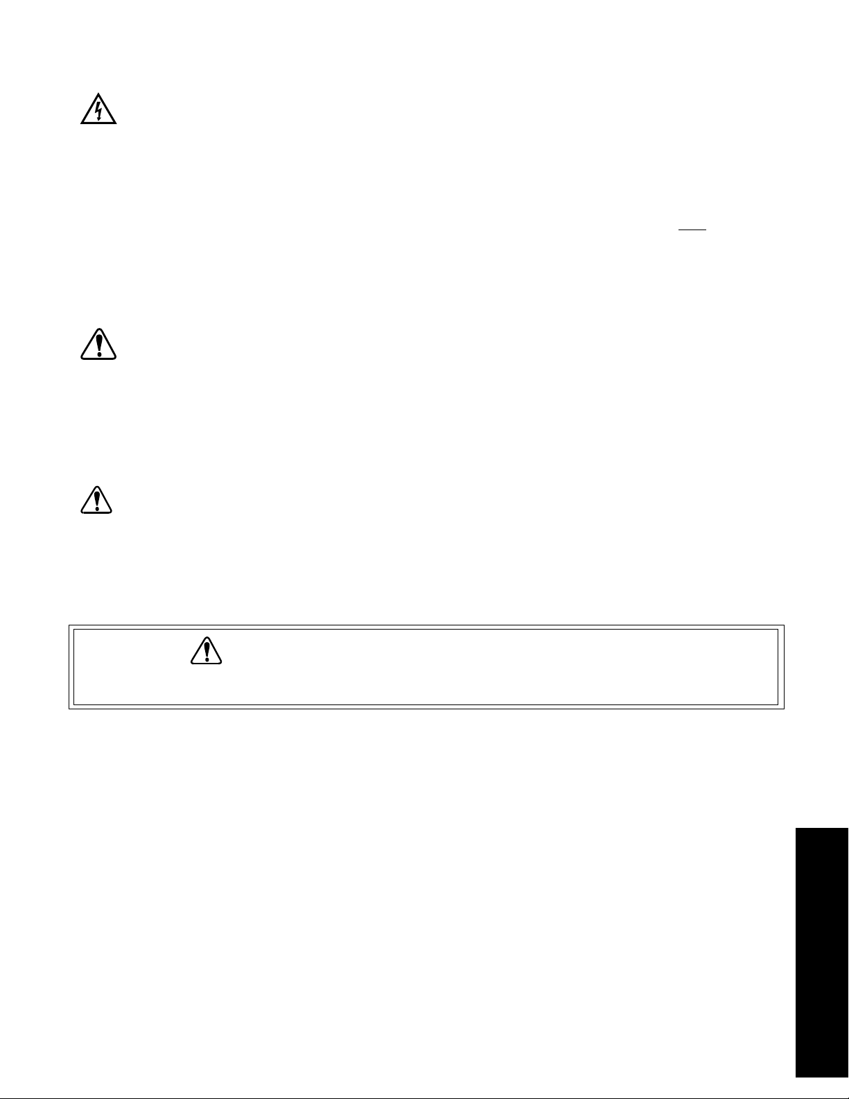
PRECAUZIONI RIGUARDANTI LA SICUREZZA
PERICOLI: NON applicare MAI tensione in corrente alternata direttamente al connettore di INGRESSO
DELL’ALIMENTAZIONE ESTERNA nelquadrocomandianteriore;l’applicazioneditensione in corrente
alternatapuòcausare infortuni chepossonoessere mortali perl’operatoree distruggere l’apparecchio;
per metteresottotensionel’apparecchiomediante una fonte di corrente alternata, utilizzaresoloilcon
vertitore di c.a.-c.c. in dotazione;
NON provocare MAI un corto circuito dei morsetti della batteria e non collegarli tra di loro perché, cosí
facendo, la batteria si riscalderebbe rapidamente e si avrebbe un’esplosione che provocherebbe gravi
lesioni, anche mortali, all’operatore;
-
il convertitore di c.a.-c.c. è designato per USO IN AMBIENTI INTERNI SOLAMENTE; NON
ambienti esterni per caricare la batteria o per mettere l’azionamento sotto tensione; ignorando questa
avvertenza di pericolo, si corre il rischio di gravi lesioni, scosse elettriche e/o la morte;
NON BRUCIARE O INCINERARE LA BATTERIA PERCHÉ POTREBBE ESPLODERE CAUSANDO GRAVI
LESIONI ANCHE MORTALI A CHI SI TROVA NELLA ZONA (eliminare la batteria vecchia riciclandola).
USARE CAUTELA: non invertire le connessioni alla batteria perché, cosí facendo, si provocano danni all’apparecchio;
primadiusare l’apparecchioper laprimavolta, caricarlocompletamente;se labatteriaètotalmentesca
rica e si cerca di fare funzionare l’apparecchio, si rischia di danneggiare la batteria interna;
l’immersione o la sommersione dell’apparecchio provoca il malfunzionamento ed eventuali danni
all’apparecchio stesso;
sesiutilizzano testepompanti etubidi dimensionieformulazioni diversedaquellespecificatein questo
manuale o sesimontanoesiusanodue o più teste pompanti contemporaneamente, l’apparecchio non
può funzionare correttamente e si rischia di danneggiarlo.
ATTENZIONE: larottura deitubipuò causarelospruzzo delfluidodallapompa;prendere ledovuteprecauzioni perpro-
teggere l’operatore e l’attrezzatura;
prima di rimuovere o montarelatestapompanteoitubi,spegnerel’azionamento,disinnestaretuttii si-
stemi di alimentazione dell’apparecchio, inclusi il convertitore di c.a-c.c., l’adattatore di alimentazione
per usoautomobilisticoodaltreeventualifonti di alimentazione; impostare l’interruttore della modalità
di funzionamento, RUN/CHARGE (funzionamento/carica) alla posizione CHARGE e impostare tutti gli
altri interruttori alla posizione Off; questo per evitare che le dita o gli indumenti sciolti rimangano presi
nel meccanismo dell’azionamento.
utilizzarlo in
-
ATTENZIONE: RESTRIZIONI SULL’USO DEL PRODOTTO
Questo prodotto non è progettato per apparecchiature che agiscono sul paziente e non è inteso, tra gli altri, per usi medici e
odontoiatrici.Diconseguenzanonè statosottoposto all’approvazionedellaFDA,l’entestatunitense perglialimentiei farmaci.
63
ITALIANO
Page 65

INTRODUZIONE E DESCRIZIONE GENERALE
Conl’azionamentoMASTERFLEX®E/S™(campionatureambientali)la pompa funzionaadunavelocità tra 70e400giri/min in senso
orario e antiorario per scaricare la tubazione e per la campionatura di liquidi.
L’azionamentoel’impiantodicarica sonolimitatidalla correnteesonoprotetticontro lapolaritàinversadell’alimentazionee letensioni
transitorie.
L’azionamentopuòfunzionare con labatteriainterna,con unafontedialimentazione esternaa12Vc.c. o a115Vc.a. o a230Vc.a. se
si utilizza il convertitore di c.a.-c.c. in dotazione.
L’azionamento ha una batteria antidispersione incorporata ed un sistema di carica che consente all’apparecchio di essere ricaricato
daunafonte dialimentazionein c.a.usandoil convertitoredic.a.-c.c. indotazioneo dall’impiantoelettricoa 12Vc.c.di unautoveicolo,
se utilizzato con l’adattatore di alimentazione per uso automobilistico.
È progettato in modo che accetti e alimenti una testa pompante e tubazione MASTERFLEX
EASY-LOAD
®
o PTFE per il trasferimento di liquidi e campionature effettuati in campo.
®
L/S®Standard, QUICK LOAD®,
L’apparecchiohauna custodiaprotettivadialtavisibilità. Ilquadrocomandi eicomandi dell’azionamentosonoprotettisecondola nor
mativa IP54 solo quando la testa pompante è montata sull’azionamento.
Sel’azionamentoè chiusoevienefatto cadereinunlago oinun corsod’acqua,rimanea gallaperalmeno30 minutiondeconsentirne
il recupero.
ALTEZZA DI ASPIRAZIONE
-
Lacombinazionedell’azionamentoMASTERFLEX®E/S™edellatestapompante singola MASTERFLEX puòsollevareverticalmen
teunacampionaturad’acquadi 7,92metrimassimo.Questacapacità vienedettaaltezzadiaspirazione eviene misuratadallasuperfi
cie del liquido alla testa pompante.
Seilliquidodicui occorreeffettuare ilprelievohaunaviscosità odensitàsuperioriaquella dell’acqua,l’altezza diaspirazioneèridotta.
MESSA A PUNTO
1. L’azionamento è stato imballato con cura onde proteggerlo durante il trasporto dalla fabbrica alla sua destinazione finale. Dopo
aver aperto la confezione, conservare il materiale di imballaggio fino a quando non si è sicuri che il prodotto funzioni correttamente.
L’azionamento consiste dei seguenti elementi:
(1) unità azionamento
(1) convertitore di c.a.-c.c.
(2) chiavi per le chiusure
(1) Manuale di istruzione
(1) scheda della garanzia
(1) busta con accessori
USARE CAUTELA: se siutilizzanotestepompantie tubididimensioni eformulazionidiverse daquelle specificateinquesto
manuale o sesimontanoesiusanodue o più teste pompanti contemporaneamente, l’apparecchio non
può funzionare correttamente e si rischia di danneggiarlo.
ATTENZIONE: prima dirimuovereomontarelatestapompanteoitubi,spegnere l’azionamento, disinnestare tutti i si
stemi di alimentazione dell’apparecchio, inclusi il convertitore di c.a-c.c., l’adattatore di alimentazione
per usoautomobilisticoodaltreeventualifonti di alimentazione; impostare l’interruttore della modalità
di funzionamento, RUN/CHARGE (funzionamento/carica) alla posizione CHARGE e impostare tutti gli
altri interruttori alla posizione Off; questo per evitare che le dita o gli indumenti sciolti rimangano presi
nel meccanismo dell’azionamento.
-
-
-
2. L’azionamento non include la testa pompante o i tubi. L’azionamento può azionare una (1) delle seguenti teste pompanti:
MASTERFLEX
Per i codici di catalogo delle teste pompanti e delle tubazioni,
Per la portata e l’altezza di aspirazione,
®
L/S®Standard, L/S QUICK LOAD, L/S EASY-LOAD o la testa pompante con tubazione L/S PTFE.
vedi
Appendice A.
vedi
Appendice B.
64
Page 66

Selezionareunadelle teste pompantielaformulazione ditubiMASTERFLEXconsigliate emontarlasull’azionamentoseguendo
le istruzioni del manuale della testa pompante.
NOTA: PRESTAZIONE OTTIMALE ALL’AVVIO
Ilmaggiorcaricoper la pompaèall’avvio di unnuovopezzodi tubo. Perunaprestazioneottimale all’avvio diunnuovo tubo, met
tereinfunzioneil meccanismodell’azionamentoedattivare l’interruttore MAXper30secondi. Unavoltaavviatoil tubo, rilasciare
l’interruttore MAX e regolare la velocità della pompa mediante l’apposita manopola regolatrice.
Per una prestazione ottimale e facilità d’uso, si consiglia di impiegare la testa pompante con tubi PTFE o EASY-LOAD.
ATTENZIONE: larottura deitubipuò causarelospruzzo delfluidodallapompa;prendere ledovuteprecauzioni perpro
teggere l’operatore e l’attrezzatura.
COMANDI E FUNZIONI
I comandi sono divisi in due settori.
Nel quadro comandi a sinistra si trovano i comandi per l’alimentazione e la modalità di funzionamento e servono a selezionare o la
messa in funzione dell’azionamento o la carica della batteria.
Nel quadro comandi a destra si trovano i comandi per il meccanismo di azionamento, ad esempio il senso di marcia e la velocità.
I comandi dell’azionamento possono funzionare solo dopo aver effettuato le corrette selezioni nel settore di sinistra per i comandi
dell’alimentazione.
D—Spia dell’indicatore
A—Ingresso alimentazione esterna
B—Interruttore di selezione della
fonte di alimentazione
di carica
C—Interruttore di selezione della modalità di funzionamento
K—Indicatore dell’alimentazione
all’azionamento
-
-
F—Indicatore dello stato della batteria
E—Interruttore di abilitazione dello
stato della batteria
G—Indicatore del dispositivo di
blocco della carica
J—Max
I—Regolazione della velocità
H—Selezione del senso di rotazione della
pompa e interruttore On/Off.
Guarnizione sigillante della testa pompante
FIGURA 1 QUADRO COMANDI
A. INGRESSO DELL’ALIMENTAZIONE ESTERNA
Connettore coassiale da 2,5 mm per alimentare corrente continua all’azionamento per caricare la batteria interna o mettere in
funzione l’azionamento mediante una fonte di alimentazione diversa dalla batteria interna. Lo spinotto centrale è positivo (+), il
manicotto è negativo (–).
B. INTERRUTTORE DI SELEZIONE DELLA FONTE DI ALIMENTAZIONE
Serve all’operatore per scegliere se usare la BATTERIA interna o una fonte di alimentazione ESTERNA per alimentare il
meccanismo dell’azionamento.
C. INTERRUTTORE DI SELEZIONE DELLA MODALITÀ DI FUNZIONAMENTO
Serve all’operatore per scegliere RUN (funzionamento) per azionare la pompa o CHARGE (carica) per caricare la batteria.
Nota: la batterianonpuò esserecaricatamentre lapompaèinfunzione;èpossibile selezionarel’unao l’altraopzione,ma non
entrambe; nella posizione CHARGE (carica), tutte le altre funzioni sono disattivate.
65
Page 67

D. SPIA DELL’INDICATORE DI CARICA
Diodo luminoso verde (LED) che si illumina quando l’alimentazione esterna è stata applicata e l’apparecchio è in modalità di
carica della batteria.
E. INTERRUTTORE DI ABILITAZIONE DELLO STATO DELLA BATTERIA
Spostando l’interruttore verso l’alto o verso il basso e mantenendo la posizione si attiva l’indicatore dello stato della batteria.
F.
INDICATORE DELLO STATO DELLA BATTERIA
Si illumina in tre modi diversi per indicare il potenziale di carica della batteria.
Verde continuo = batteria a piena carica.
Verde lampeggiante = batteria parzialmente scarica, rimane il 50% o meno del sua capacità.
Rosso = batteria completamente scarica. Ricaricare immediatamente.
G.
INDICATORE DEL DISPOSITIVO DI BLOCCO DELLA CARICA
Siilluminaquando la temperaturaambientenell’alloggiamento ètroppoelevataper potercaricarela batteria sicuramente.Seè il
luminato, il circuito di carica è stato disattivato. Il sistema può essere azionato, ma non caricato.
H. INTERRUTTORE ON/OFF E DI SELEZIONE DEL SENSO DI ROTAZIONE DELLA POMPA
Questointerruttoreattiva (ON) edisattivata(OFF)la pompaeconsenteall’operatore di selezionareilsenso di rotazione:insenso
orario o antiorario. Quando è al centro è in posizione Off.
I. REGOLAZIONE DELLA VELOCITÀ
Ilpotenziometroadungiro (1)regola lavelocitàdellapompa.La velocitàaumentainsensoorario ediminuisce insensoantiorario.
J. MAX
Un interruttore di by-pass della circuiteria regolatrice della velocità per far funzionare la pompa alla sua massima velocità
nominale.Puòessere usatoperadescare oscaricareitubiasecondadellaposizione dell’interruttore(H)di selezionedelsenso di
rotazione.
K. INDICATORE DELL’ALIMENTAZIONE ALL’AZIONAMENTO
Diodo luminoso (LED) verde che si illumina quando l’interruttore di selezione del senso di rotazione (ON/OFF) si trova in una
posizione che non sia Off, il che vuol dire che il meccanismo dell’azionamento è sotto tensione.
-
FUNZIONAMENTO DELL’AZIONAMENTO
1. Selezione della modalità di funzionamento
L’apparecchio può essere usato in tre modalità diverse:
A. carica della batteria interna; tutte le altre funzioni sono disabilitate;
B. azionamento in funzione con alimentato da batteria interna;
C. azionamento in funzione mediante alimentazione esterna.
2. Istruzioni per il funzionamento
Carica della batteria interna mediante convertitore di c.a.-c.c. o una fonte di alimentazione esterna
USARE CAUTELA: prima di usare l’apparecchio per la prima volta, caricarlo completamente; se la batteria è totalmente
scarica e si cerca di fare funzionare l’apparecchio, si rischia di danneggiare la batteria interna.
A.
Collegare all’azionamento il convertitore di c.a.-c.c. in dotazione sollevando il coperchio del connettore di INGRESSO
vedi
DELL’ALIMENTAZIONE ESTERNA (A) e innestando la spina coassiale da 2,5 mm nel connettore (
PERICOLO: NON applicare MAI tensione in corrente alternata direttamente al connettore di INGRESSO
DELL’ALIMENTAZIONE ESTERNA nelquadrocomandianteriore;l’applicazioneditensione in corrente
alternatapuòcausare infortuni chepossonoessere mortali perl’operatoree distruggere l’apparecchio;
per metteresottotensionel’apparecchiomediante una fonte di corrente alternata, utilizzaresoloilcon
vertitore di c.a.-c.c. in dotazione.
B.
Collegare ilconvertitoredic.a.-c.c. ad una fonte di alimentazioneincorrentealternata.Impostare l’interruttore di sele
zione della fonte di alimentazione (B), EXTERNAL/BATTERY (esterna/batteria), alla posizione BATTERY.
C.
Impostarel’interruttoredi selezionedellamodalità difunzionamento (C), RUN/CHARGE(funzionamento/carica), alla
posizione CHARGE.
D.
L’indicatore di carica, CHARGE, si illumina.
E.
Caricare la batteria per 8–12 ore.
Figura 1).
-
-
66
Page 68
Funzionamento della pompa con la batteria interna
PERICOLO: il convertitore di c.a.-c.c. è designato per USO IN AMBIENTI INTERNI SOLAMENTE; NON utilizzarlo in
ambienti esterni per caricare la batteria o per mettere l’azionamento sotto tensione; ignorando questa
avvertenza di pericolo, si corre il rischio di gravi lesioni, scosse elettriche e/o la morte.
USARE CAUTELA: prima diusarel’apparecchioperla primavolta,caricarlo completamente;sela batteriaè totalmentesca
rica e si cerca di fare funzionare l’apparecchio, si rischia di danneggiare la batteria interna.
A.
Impostare l’interruttore di selezione della fonte di alimentazione (B), EXTERNAL/BATTERY (esterna/batteria), alla
posizione BATTERY.
B.
Impostarel’interruttoredi selezionedellamodalità difunzionamento (C), RUN/CHARGE(funzionamento/carica), alla
posizione RUN.
C.
Selezionarel’interruttoreOn/Off e diselezionedel senso dirotazionedella pompa (H)in senso orariooantiorario (
Figura1).Prima di cambiareilsensodi rotazione,disinnestarel’alimentazione,cioé impostare l’interruttoredelsenso di rota
zione alla posizione di centro o Off.
D.
Regolare la portata della pompa mediante l’apposito dispositivo regolatore ad 1 giro (I), girando la manopola in senso
orario per aumentare la portata e in senso antiorario per diminuirla.
E.
Per adescare il tubo, muovere l’interruttore MAX (J) verso l’alto o verso il basso per azionare la pompa alla massima
velocità.
Verifica del potenziale di carica della batteria disponibile
NOTA: per la migliore accuratezza, controllare la batteria interna con la pompa in funzione.
A.
Impostare l’interruttore di selezione della fonte di alimentazione (B), EXTERNAL/BATTERY (esterna o da batteria),
alla posizione BATTERY.
B.
Impostarel’interruttoredi selezionedellamodalità difunzionamento (C), RUN/CHARGE(funzionamento/carica), alla
posizione RUN.
C.
Selezionare l’interruttore On/Off e di selezione del senso di rotazione della pompa (H ) in senso orario o in senso
antiorario (
del senso di rotazione alla posizione di centro o Off.
D.
Spostare l’interruttore dello stato dellabatteriaversol’altooversoilbassoe tenerlo in posizione. L’indicatore dello stato
della batteria si illumina.
Verde continuo = batteria a piena carica.
Verde lampeggiante = batteria parzialmente scarica, rimane il 50% o meno del sua capacità.
Rosso = batteria completamente scarica. Ricaricare immediatamente.
vedi
Figura 1). Prima di cambiare il senso di rotazione, disinnestare l’alimentazione, cioé impostare l’interruttore
vedi
-
-
Funzionamento mediante batteria esterna a 12V, adattatore di alimentazione per uso automobilistico o altra fonte di
alimentazione a corrente continua.
PERICOLO: il convertitore di c.a.-c.c. è designato per USO IN AMBIENTI INTERNI SOLAMENTE; NON utilizzarlo in
ambienti esterni per caricare la batteria o per mettere l’azionamento sotto tensione; ignorando questa
avvertenza di pericolo, si corre il rischio di gravi lesioni, scosse elettriche e/o la morte.
USARE CAUTELA: prima di usare l’apparecchio per la prima volta, caricarlo completamente; se la batteria è totalmente
scarica e si cerca di fare funzionare l’apparecchio, si rischia di danneggiare la batteria interna.
A.
Impostare l’interruttore di selezione della fonte di alimentazione (B), EXTERNAL/BATTERY (esterna/batteria), alla
posizione EXTERNAL.
B.
Impostarel’interruttoredi selezionedellamodalità difunzionamento (C), RUN/CHARGE(funzionamento/carica), alla
posizione RUN.
C.
Selezionarel’interruttoreOn/Off e diselezionedel senso dirotazionedella pompa (H)in senso orariooantiorario (
Figura 1). Prima di cambiare il senso di rotazione, disinnestare l’alimentazione, cioé impostare l’interruttore del senso di
rotazione alla posizione di centro o Off.
D.
Regolare la portata della pompa mediante l’apposito dispositivo regolatore ad 1 giro (I), girando la manopola in senso
orario per aumentare la portata e in senso antiorario per diminuirla.
E.
Per adescare il tubo, muovere l’interruttore MAX (J), verso l’alto o verso il basso per azionare la pompa alla massima
velocità.
vedi
67
Page 69

Funzionamento della pompa mediante alimentazione a corrente alternata
PERICOLO: NON applicare MAI tensione in corrente alternata direttamente al connettore di INGRESSO
DELL’ALIMENTAZIONE ESTERNA nelquadrocomandianteriore;l’applicazioneditensione in corrente
alternatapuòcausare infortuni chepossonoessere mortali perl’operatoree distruggere l’apparecchio;
per metteresottotensionel’apparecchiomediante una fonte di corrente alternata, utilizzaresoloilcon
vertitore di c.a.-c.c. in dotazione.
-
PERICOLO: il convertitore di c.a.-c.c. è designato per USO IN AMBIENTI INTERNI SOLAMENTE; NON
utilizzarlo in
ambienti esterni per caricare la batteria o per mettere l’azionamento sotto tensione; ignorando questa
avvertenza di pericolo, si corre il rischio di gravi lesioni, scosse elettriche e/o la morte.
A.
Collegare all’azionamento il convertitore di c.a.-c.c. in dotazione sollevando il coperchio del connettore di INGRESSO
vedi
DELL’ALIMENTAZIONE ESTERNA (A) e innestando la spina coassiale da 2,5 mm nel connettore (
B.
Collegareilconvertitore di c.a.-c.c.aduna fonte dialimentazionein correntealternata.Impostare l’interruttore (B)di
selezione della fonte di alimentazione, EXTERNAL/BATTERY (esterna/batteria) alla posizione EXTERNAL.
C.
Impostarel’interruttoredi selezionedellamodalità difunzionamento (C), RUN/CHARGE(funzionamento/carica), alla
posizione RUN.
D.
Selezionare l’interruttore On/Off e di selezione del senso di rotazione della pompa (H ) in senso orario o in senso
antiorario (
del senso di rotazione alla posizione di centro o Off.
E.
Regolarelaportatadellapompa mediantel’appositodispositivoregolatoread 1giro(I),girandola manopolainsensoorario
per aumentare la portata e in senso antiorario per diminuirla.
F.
Per adescare il tubo, muovere l’interruttore MAX (J), verso l’alto o verso il basso e tenerlo in posizione per azionare la
pompa alla massima velocità.
vedi
Figura 1). Prima di cambiare il senso di rotazione, disinnestare l’alimentazione, cioé impostare l’interruttore
Figura 1).
MANUTENZIONE
USARE CAUTELA: l’immersione o la sommersione dell’apparecchio provoca il malfunzionamento ed eventuali danni
all’apparecchio stesso.
Pulizia
Pulire le superfici esterne ed interne della custodia e il quadro comandi con panno asciutto o umido e un detersivo leggero. Non immergerla mai e non usare fluidi in quantità eccessive.
Batteria interna
Labatteriainternaèantidispersione esigillataenonha elementio componentisucuisipossano effettuareinterventidimanutenzione.
È costruita in modo che possa funzionare per anni purché la manutenzione venga effettuata correttamente.
USARE CAUTELA: prima di usare l’apparecchio per la prima volta, caricarlo completamente; se la batteria è totalmente
scarica e si cerca di fare funzionare l’apparecchio, si rischia di danneggiare la batteria interna.
A. Prima di usare l’apparecchio per la prima volta, caricarlo completamente.
B. Se possibile conservare l’apparecchio a temperatura ambiente.
C. Conservare sempre l’apparecchio in condizione di piena carica.
D. Col passar del tempo, la batteria si autoscarica parzialmente. La velocità con cui si scarica aumenta con l’aumentare della
temperatura. Si consiglia di tenere in funzione l’apparecchio per un minimo di 2 ore ogni sei mesi e poi ricaricarlo durante la
notte. In tal modo la durata potenziale della batteria interna viene estesa al massimo.
E. Non lasciare l’apparecchio sotto carica per più di 24 ore. Caricando la batteria più a lungo del necessario se ne provoca il ri
scaldamento interno ed eventualmente il malfunzionamento prematuro. Una batteria completamente scarica si ricarica in
8–12ore.Unavoltache labatteriasiècompletamente ricaricata,ilcircuitoregolatore/caricatoredella batteriainternamettela
batteria in modalità di mantenimento di carica per impedirne il sovraccarico.
Carica della batteria interna mediante una fonte di corrente alternata
PERICOLO: NON applicare MAI tensione in corrente alternata direttamente al connettore di INGRESSO
DELL’ALIMENTAZIONE ESTERNA nelquadrocomandianteriore;l’applicazioneditensione in corrente
alternatapuòcausare infortuni chepossonoessere mortali perl’operatoree distruggere l’apparecchio;
per metteresottotensionel’apparecchiomediante una fonte di corrente alternata, utilizzaresoloilcon
vertitore di c.a.-c.c. in dotazione.
68
-
-
Page 70

A.
Collegare il convertitore di c.a.-c.c. in dotazione sollevando il coperchio del connettore di INGRESSO
vedi
DELL’ALIMENTAZIONE ESTERNA (A) e innestando la spina coassiale da 2,5 mm nel connettore (
B.
Collegare il convertitore di c.a.-c.c. ad una fonte di corrente alternata.
C.
Impostarel’interruttoredi selezionedellamodalità difunzionamento (C), RUN/CHARGE(funzionamento/carica), alla
Figura 1).
posizione CHARGE.
D. Quando il circuito di carica è sotto tensione, l’indicatore di carica si illumina.
E. Una batteria completamente scarica, si ricarica completamente in 8–12 ore.
Carica della batteria interna mediante batteria esterna a 12V, adattatore di alimentazione per uso automobilistico
07571-50 o altra fonte di alimentazione incorrente continua.
A.
Collegare la fonte di alimentazione esterna sollevando il
coperchio del connettore di INGRESSO
DELL’ALIMENTAZIONE ESTERNA (A) e innestando la
vedi
spina coassiale da 2,5 mm nel connettore (
B. Collegare l’adattatore di alimentazione per uso automobili
stico 07571-50 all’accendisigari nel veicolo.
C.
Impostare l’interruttore di selezione della modalità di
funzionamento (C), RUN/CHARGE (funzionamento/
carica), alla posizione CHARGE.
D. Quando il circuito di carica è sotto tensione, l’indicatore di
carica si illumina.
E. Una batteria completamente scarica, si ricarica completa
mente in 8–12 ore.
vedi
Sostituzione della batteria interna (
Figura 2)
Figura 1).
Dadi #6-32
-
-
SEMS, in
4 punti
Staffa—
barra di
fermo
batteria
Batteria:
notare
posizione
morsetti
PERICOLO: NON provocare MAI un corto circuito dei
morsetti della batteria e non collegarli tra di
loro perché, cosí facendo, la batteria si
riscalderebbe rapidamente e si avrebbe
un’esplosione che provocherebbe gravi le-
FIGURA 2. SOSTITUZIONE DELLA BATTERIA
sioni, anche mortali, all’operatore.
A. Impostaretuttigliinterruttoridel quadro comandi allaposizionediOffe scollegare il convertitoredic.a.-c.c.od altre eventuali
fonti di alimentazione esterne.
B. Con un cacciavite Phillips n°2, rimuovere le dodici (12) viti che tengono l’insieme del quadro comandi nell’alloggiamento.
C. Con cura rimuovere il quadro comandi dall’alloggiamento e scollegare i conduttori elettrici della batteria.
D. Rimuovere imorsettiascollegamentorapido forniticonlabatteriadiricambioe metterlisopraimorsettidella vecchiabatteria.
E. Con una chiave per dadi di 5/16 pollici, allentare e rimuovere i quattro (4) dadi e la staffa che tengono la barra di fermo della
batteria in posizione.
F. Rimuovere la batteria.
USARE CAUTELA: non invertire le connessioni alla batteria perché, cosí facendo, si provocano danni all’apparecchio.
G.
Per montare la batteria seguire le istruzioni in senso inverso. Collegare il connettore ROSSO al morsetto della batteria
contrassegnato + (positivo). Collegare il connettore NERO al morsetto della batteria contrassegnato – (negativo).
USARE CAUTELA: prima diusarel’apparecchioperla primavolta,caricarlo completamente;sela batteriaè totalmentesca
rica e si cerca di fare funzionare l’apparecchio, si rischia di danneggiare la batteria interna.
H. Dopo averla sostituita, caricare la batteria completamente.
Vedi
CARICA DELLA BATTERIA.
PERICOLO: NONBRUCIAREO INCINERARE LA BATTERIA PERCHÉ POTREBBE ESPLODERE CAUSANDO GRAVI
LESIONI ANCHE MORTALI A CHI SI TROVA NELLA ZONA (eliminare la batteria vecchia riciclandola).
-
69
Page 71
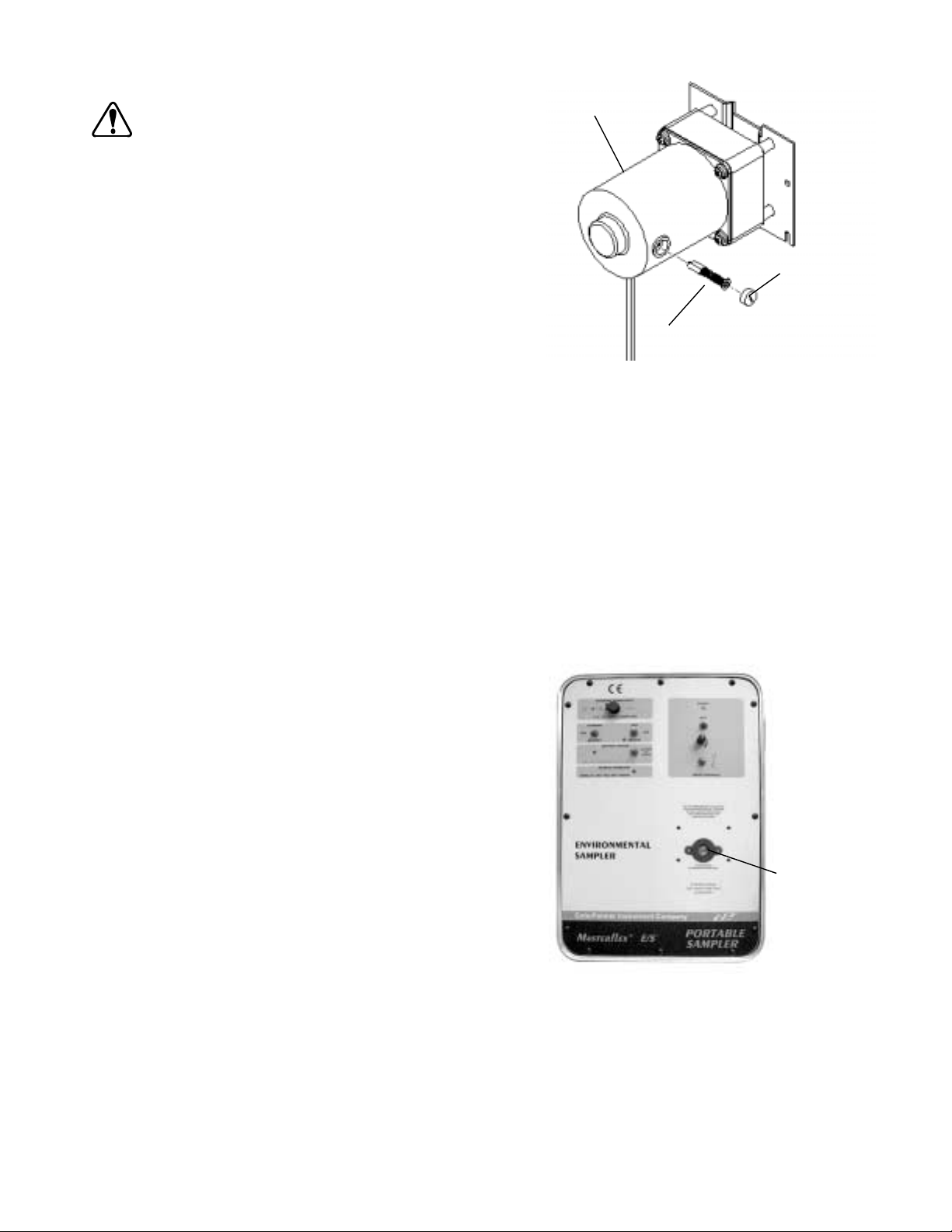
Controllo/sostituzione delle spazzole del motore (vedi Figura 3)
ATTENZIONE: primadirimuovere omontarela testapompanteo
itubi,spegnerel’azionamento, disinnestare tuttii
Motore
sistemidialimentazione dell’apparecchio,inclusi
il convertitore di c.a-c.c., l’adattatore di alimenta
zione per uso automobilistico od altre eventuali
fonti di alimentazione; impostare l’interruttore
della modalità di funzionamento, RUN/CHARGE
(funzionamento/carica) alla posizione CHARGE e
impostare tutti gli altri interruttori alla posizione
Off; questo per evitare che le dita o gli indumenti
sciolti rimangano presi nel meccanismo
Tappo spazzola
motore
dell’azionamento.
NOTA: le spazzole devono essere controllate ogni 2000 ore d’esercizio o
ogni 6 mesi oppure se il funzionamento è erratico.
Insieme spazzola motore
A. Impostare tutti gli interruttori del quadro comandi alla posizione di
Off e scollegare l’eventuale convertitore di c.a.-c.c.
B. ConuncacciavitePhillips n°2, rimuovere ledodici(12)viti che ten
gono l’insieme del quadro comandi nell’alloggiamento.
C. Con cura rimuovere il quadrocomandidall’alloggiamentoescolle
-
FIGURA 3. SOSTITUZIONE DELLE
SPAZZOLE MOTORE
-
gare i conduttori dalla batteria.
D. Con un cacciavite, rimuovere le spazzole e ruotare il portaspazzole di 90° in senso antiorario. La spazzola dovrebbe saltare
fuori.
E. Pulire le spazzole con aspirapolvere asportando tutta la polvere dalle aperture del portaspazzole.
F. Ispezionare le spazzole e, se misurano 4 mm o meno di lunghezza, sostituirle.
G. Ripetere il passo D per rimuovere l’altra spazzola.
H. Per rimontarelespazzole, seguireleistruzioniinsenso inverso,ricollegarelabatteriae montareilquadro comandi.Collegare
il connettore ROSSO al morsetto della batteria contrassegnato + (positivo). Collegare il connettore NERO al morsetto della
batteria contrassegnato – (negativo).
Sostituzione della guarnizione sigillante della testa pompante (
vedi
Una guarnizione sigillante della testa pompante è in dotazione ad ogni
apparecchio e si trova nel quadro comandi intorno all’albero di uscita
dell’azionamento.Colpassar del tempoeconil cambiofrequentedelleteste pompanti, la guarnizione si deteriora.Permantenerel’integritàprotet
tiva a norma IP dell’apparecchio, laguarnizionedeveesserecambiatase
si notano una deteriorazione o delle perdite oppure dopo uno o due anni
d’esercizio, qualunque situazione si verifichi prima.
Per sostituire la guarnizione, spellare la guarnizione e il suo rivestimento
adesivodalquadrocomandi.Fare attenzionearimuovere completamente
ogni residuo della guarnizione. Il profilo della guarnizione è mostrato nel
quadro comandi. Togliere il rivestimento rimovibile dal supporto adesivo
dellanuovaguarnizione ecollocarela nuovaguarnizionenel profilo,come
mostrato nel quadro comandi.
Figura 4)
-
Guarnizione
sigillante della
testa pompante
FIGURA 4 GUARNIZIONE SIGILLANTE
DELLA TESTA POMPANTE
70
Page 72

INDIVIDUAZIONE E RISOLUZIONE DI PROBLEMI
1. L’azionamento non fun zio na con ali men ta zio ne dal la bat te ria in ter na.
A.
Ve ri fi ca re che l’interruttore di se le zio ne del la fon te di ali men ta zio ne (B), EXTERNAL/BATTERY (ester na/ bat te ria) sia
im po sta to a BATTERY .
B.
Ve ri fi ca re che l’interruttore di se le zio ne del la mo da li tà di fun zio na men to (C), RUN/CHARGE (fun zio na men to/ca ri ca) ,
sia im po sta to a RUN .
C. Ve ri fi ca re che la te sta pom pan te, la di men sio ne e la for mu la zio ne del tubo sia no cor ret te e sia no quel le con si glia te per que sto
azio na men to.
D. Se si uti liz za una te sta pom pan te PTFE, mon ta re e av via re il tubo se guen do le istru zio ni del ma nua le del la te sta pom pan te.
Se il let to di oc clu sio ne si ser ra ec ces si va men te, il mec ca ni smo dell’azionamento può in cep par si. Ser ra re il let to di oc clu sio ne
gra dual men te se guen do le istru zio ni del ma nua le del la te sta pom pan te.
E.
Ve ri fi ca re che l’ in ter rut to re av vio/ar re sto e di se le zio ne del la ro ta zio ne del la pom pa (H) sia im po sta to o alla po si zio ne in
sen so ora rio o in quel la in sen so an tio ra rio , a se con da del sen so di ro ta zio ne vo lu to. L’ in di ca to re dell’alimentazione (K)
nei co man di dell’azionamento è il lu mi na to.
F.
Azio na re o abi li ta re l’ in di ca to re del lo sta to del la bat te ria (F) . Se l’indicatore è ROSSO, ri ca ri ca re la bat te ria im me dia ta men -
te. La ca ri ca del la bat te ria in ter na si è esa u ri ta o la bat te ria è sca ri ca.
G.
Se l’ in di ca to re del lo sta to del la bat te ria (F) non si il lu mi na, ri mu o ve re il qua dro co man di e con trol la re che non ci sia no con -
nes sio ni alla bat te ria al len ta te.
H. Per con trol la re il po ten zia le di ca ri ca del la bat te ria, uti liz za re un mul ti me tro d i gi ta le (DMM) im po sta to ad un vol tag gio in cor -
ren te con ti nua. Se è in fe rio re a 9 Volt, so sti tu i re la bat te ria.
I. Se nes su na del le so lu zio ni sum men zio na te ri sol ve il pro ble ma, ri vol ger si al ri ven di to re au to riz za to per as si sten za.
2. L’azionamento non fun zio na con ali men ta zio ne for ni ta dal con ver ti to re di c.a.-c.c.
A.
Ve ri fi ca re che l’interruttore di se le zio ne del la fon te di ali men ta zio ne (B), EXTERNAL/BATTERY (ester na/b at te ria) sia
im po sta to alla po si zio ne EXTERNAL .
B.
Ve ri fi ca re che l’interruttore di se le zio ne del la mo da li tà di fun zio na men to (C) sia im po sta to alla po si zio ne RUN .
C. Ve ri fi ca re che la te sta pom pan te, la di men sio ne e la for mu la zio ne del tubo sia no cor ret te e sia no quel le con si glia te per que sto
azio na men to.
D. Se si uti liz za una te sta pom pan te PTFE, mon ta re e av via re il tubo se guen do le istru zio ni del ma nua le del la te sta pom pan te.
Se il let to di oc clu sio ne si ser ra ec ces si va men te, il mec ca ni smo dell’azionamento può in cep par si. Ser ra re il let to di oc clu sio ne
gra dual men te, se guen do le istru zio ni del ma nua le del la te sta pom pan te.
E.
Ve ri fi ca re che l’interruttore av vio/ar re sto di se le zio ne del la ro ta zio ne del la pom pa (H) sia im po sta to o alla ro ta zio ne in
sen so ora rio o a quel la in sen so an tio ra rio , a se con da del sen so di ro ta zio ne vo lu to. L’ in di ca to re dell’alimentazione (K)
nei co man di dell’azionamento è il lu mi na to.
F. Ve ri fi ca re che la spi na co as sia le sia com ple ta men te in se ri ta nel con net to re di in gres so dell’alimentazione ester na
dell’apparecchio.
G. Ve ri fi ca re che la ten sio ne in c.a. sia pre sen te nel la pre sa in c.a. a cui il con ver ti t o re di c.a.-c.c. è col le ga to.
H.
Ve ri fi ca re la ten sio ne in c.c. pres so il con net to re co as sia le da 2,5 mm. Deve es se re al me no a 13 Volt c.c. Dato che il di spo si -
ti vo non con tie ne al cun ele men to su cui l’operatore pos sa ef fet tua re in ter ven ti, non è pos si bi le ef fet tua re la ma nu -
ten zio ne del con ver ti to re di c.a.-c.c.
I. Se nes su na del le so lu zio ni sum men zio na te ri sol ve il pro ble ma, ri vol ger si al ri ven di to re au to riz za to per as si sten za.
3. L’azionamento non fun zio na con l’adattatore di ali men ta zio ne per uso au to mo bi lis ti c o.
A.
Ve ri fi ca re che l’interruttore di se le zio ne del la fon te di ali men ta zio ne (B), EXTERNAL/BATTERY (ester na/b at te ria) sia
im po sta to alla po si zio ne EXTERNAL .
B.
Ve ri fi ca re che l’interruttore di se le zio ne del la mo da li tà di fun zio na men to (C) , sia im po sta to a RUN (fun zio na men to).
C. Ve ri fi ca re che la te sta pom pan te, la di men sio ne e la for mu la zio ne del tubo sia no cor ret te e sia no quel le con si glia te per que sto
azio na men to.
D. Se si uti liz za una te sta pom pan te PTFE, mon ta re e av via re il tubo se guen do le istru zio ni del ma nua le del la pom pa. Se il let to
di oc clu sio ne vie ne ser ra to ec ces si va men te, il mec ca ni smo dell’azionamento può in cep par si. Ser ra re il let to di oc clu sio ne
gra dual men te, se guen do le istru zio ni del ma nua le del la te sta pom pan te.
E.
Ve ri fi ca re che l’interruttore av vio/ar re sto di se le zio ne del la ro ta zio ne del la pom pa (H) sia im po sta to o alla ro ta zio ne in
sen so ora rio o a quel la in sen so an tio ra rio , a se con da del sen so di ro ta zio ne vo lu to. L’ in di ca to re dell’alimentazione (K)
nei co man di dell’azionamento è il lu mi na to.
F. Ve ri fi ca re che la spi na co as sia le dell’adattatore di ali men ta zio ne per uso au to mo bi li sti co sia com ple ta men te in se ri ta nel con -
net to re di in gres so dell’alimentazione ester na dell’apparecchio.
G. Ve ri fi ca re che l’adattatore di ali men ta zio ne per uso au to mo bi li sti co o il con ver ti to re di cc.a-c.c. sia no com ple ta men te in se ri ti
nell’accendisigari del ve i co lo.
H. Ve ri fi ca re che il fu si bi le dell’accendisigari non sia aper to o sal ta to.
71
Page 73

I. Verificare la tensione in corrente continua presso il connettore coassiale da 2,5 mm. Deve essere almeno a 12 Volt c.c.
J. Verificare la polarità della tensione in corrente continua presso il connettore da 2,5 mm. Il manicotto è negativo e il centro è
positivo. L’azionamento è protetto contro l’inversione di polarità e non funziona se le polarità sono invertite.
K. Se nessuna delle soluzioni summenzionate risolve il problema, rivolgersi al rivenditore autorizzato per assistenza.
4. L’indicatore della carica della batteria interna non si illumina oppure la batteria non si carica se si usa il convertitore
di c.a.-c.c.
A.
Verificarechel’interruttorediselezione della modalità difunzionamento(C),CHARGE/RUN (funzionamento/carica),
sia impostato a CHARGE.
B. Verificare che la spina coassiale del convertitore di c.a.-c.c. sia completamente inserita nel connettore di ingresso
dell’alimentazione esterna dell’apparecchio.
C. Verificare chelatensionein c.a.siapresente nella presainc.a. acuiilconvertitore dic.a.-c.c.è collegato. Verificarelatensio
ne in c.c. presso il connettore coassiale da 2,5 mm. Deve essere almeno di 13 Volt c.c.
D. Se nessuna delle soluzioni summenzionate risolve il problema, rivolgersi al rivenditore autorizzato per assistenza.
5. L’indicatore della carica della batteria interna non si illumina oppure la batteria non si carica usando l’adattatore di
alimentazione per uso automobilistico.
A.
Verificare che l’interruttore di selezione della fonte di alimentazione (B), EXTERNAL/BATTERY (esterna/batteria) sia
impostato a EXTERNAL.
B.
Verificare che l’interruttore di selezione della modalità di funzionamento (C), CHARGE/RUN (funzionamento/carica)
sia impostato alla posizione RUN.
C. Verificare che laspinacoassialedell’adattatore di alimentazione perusoautomobilisticosia inserita completamentenelcon
nettore dell’alimentazione esterna dell’azionamento.
D. Verificare chel’adattatoredialimentazioneper usoautomobilisticosiainseritocompletamentenell’accendisigaridel veicolo.
E. Verificare che il fusibile dell’accendisigari non sia aperto o saltato.
F. Verificare latensioneinc.c. pressoilconnettorecoassiale da2,5mm. Deve esserealmenoa 13Voltc.c.Verificare lapolarità
della tensione in c.c. presso il connettore.
G. L’azionamentoèprotettocontrol’inversione dellapolaritàe nonfunzionaselepolarità sonoinvertite.Ilmanicottoè negativoe
il centro è positivo.
H. Se nessuna delle soluzioni summenzionate risolve il problema, rivolgersi al rivenditore autorizzato per assistenza.
-
-
RICAMBI PER L’UTENTE
77120-21 Convertitore di c.a.-c.c. a 115V c.a.
77120-26 Convertitore di c.a.-c.c. a 230V c.a.
77500-03 Fusibili di ricambio per adattatore di alimentazione per uso automobilistico o complesso per alimentazione
ausiliaria
07571-55 Batteria 12V 7,2 Ah
07571-56 Guarnizione, testa pompante (confezione da 6)
07571-57 Elementi protettivi sigillanti, interruttori e regolatore di velocità (confezione da 6)
07571-58 Manopola e tappo, regolatore di velocità
07571-59 Kit di sostituzione delle spazzole motore, due.
07571-60 Convertitore di c.a.-c.c. a 100V c.a. (Giappone)
72
Page 74

ACCESSORI
06456-10 Connettore per tubi dentellato, 3/16 pollici (tubi dimensione L/S®15 e L/S®25)
®
06456-20 Connettore per tubi dentellato, 1/4 pollici (tubi dimensione L/S
®
07570-04 Peso tubi, idoneo per tubi di dimensione L/S
15, 24 o 25
24)
07571-50 Adattatore di alimentazione per uso automobilistico, limitato da corrente
07571-52 Complesso di alimentazione ausiliaria con caricatore 115V c.a.
07571-54 Complesso di alimentazione ausiliaria con caricatore 230V c.a.
SPECIFICHE TECNICHE
Velocità d’esercizio da 70 a 400 giri/min.
Tensione d’esercizio/frequenza:
Modello 07571-00 115V c.a. nominale 50/60 Hz (100–130) V c.a. @ 120 mA c.a.
Modello 07571-05 230V c.a. nominale 50/60 Hz (200–260) V c.a. @ 60 mA c.a.
Numero di teste pompanti: 1
Coppia-carico: 0,35 N•m, max
Senso di rotazione: orario e antiorario
Temperatura d’esercizio: da 0 °C a 50 °C
Temperature di stoccaggio: da –20 °C a 65 °C
Umidità (non-condensante): da 10% a 90%
Altitudine 2000 m
Dimensioni (lung⫻larg⫻alt): 27,94 cm ⫻ 26,04 cm ⫻ 40,64 cm
Peso: 7,49 kg
Resistenza a prodotti chimici: polietilene ad alta densità, alluminio anodizzato, acciaio inox e
Limiti di impiego custodia: IP54 secondo norma CEI529
Grado di inquinamento: grado 2 secondo norma CEI664
Categoria di impianto: categoria II secondo norma CEI664 (livello locale
Normativa:
07571-00 convertitore di c.a.-c.c. 115V c.a. conforme a UL ed approvato da
07571-05 230V (per indicazione CE):
12V c.c. nominale (11–16)V c.c. @2,4 A c.c.
12V c.c. nominale (11–16)V c.c. @2,4 A c.c.
poliestere. Tutti i materiali sono resistenti ai solventi standard.
—apparecchiature, attrezzature portatili, ecc.)
CSA. Le specifiche degli enti regolatori non sono applicabili al
resto dell’apparecchio a causa della bassa tensione;
Direttiva europea sulla compatibilità elettromagnetica
(EN 61326-1/A1: 1998)
73
Page 75

GARANZIA
Per le migliori prestazioni, utilizzare solo tubi di precisione MASTERFLEX con le pompe MASTERFLEX. L’uso di altri tubi
può invalidare la relativa garanzia.
Il produttoregarantiscechequestoprodottonondifferisceinmanierasignificativa dalle specifiche tecniche pubblicate. In caso siano
necessarie riparazioni o regolazioni entro il periodo di tempo in cui la garanzia è in vigore, il problema verrà corretto senza addebito
purché, agiudiziodelproduttore,nonsiadovuto ad uso improprio o eccessivo del prodotto. Ilcostodelleriparazionialdifuori del pe
riodoincuilagaranzia èin vigoreoicostirisultanti dall’usoimpropriooeccessivodel prodottopotranno essereacaricodelcliente.
Il periodo in cui la garanzia è in vigore per questo prodotto è indicato nell’apposita scheda.
RESTITUZIONE DEL PRODOTTO
Al finedilimitareicostieiritardi,primadi rendere il prodotto, rivolgersi al rivenditore o al produttore per ottenerel’autorizzazioneele
istruzioniperlaspedizione, sia entrocheoltrei limiti delperiodoincui la garanziaèinvigore. Nel rendereilprodotto,indicare la ragio
nedellarestituzione. Per sicurezza,imballareil prodottoconcurae assicurarlocontroeventuali danni operdite.Il clienteèritenutore
sponsabile degli eventuali danni derivanti da imballaggio non idoneo.
ASSISTENZA TECNICA
Per ulteriori informazioni sull’uso di questo prodotto, rivolgersi al produttore o al rivenditore autorizzato.
-
-
-
Cole-Parmer Instrument Company
625 East Bunker Court
Vernon Hills, Illinois U.S.A. 60061-1844
1-800-MASTERFLEX (627-8373) (U.S. and Canada only)
11 (847) 549-7600 (outside U.S.)
(847) 549-7600 (Local)
FAX (847) 247-2929 (U.S. and Canada only)
11 (847) 549-1700 (Fax outside U.S.)
www.masterflex.com
e-mail: techinfo@coleparmer.com
Barnant Company
28W092 Commercial Ave.
Barrington, Illinois U.S.A. 60010-2392
1-800-637-3739 (U.S. and Canada only)
11 (847) 381-7050 (outside U.S.)
(847) 381-7050 (Local)
11 (847) 381-7053 (Fax outside U.S.)
(847) 381-7053 (Local Fax)
www.barnant.com
e-mail: barnant@barnant.com
74
Stampato negli Stati Uniti d’America
040601
Page 76

APPENDICE A
TESTE POMPANTI, DIMENSIONE DI TUBI, FORMULAZIONE E CODICI DEI MODELLI CONSIGLIATI
CODICI MODELLI TUBI
TESTA
POMPANTE
TIPO L/S
MODELLO
POMPA n°
®
Standard 07013-20
07013-21
DIMENSIONE
TUBI
13 96400-13
SILICONE C-FLEX
06424-13 06409-13 06429-13 06485-13 06404-13 06412-13
96410-13
®
TYGON
LAB
®
TYGON
LFL
®
PHARMED
®
NORPRENE
®
FluoroelastomeroPTFE
07013-52
07014-20
07014-21
14 96400-14
96410-14
06424-14 06409-14 06429-14 06485-14 06404-14 06412-14
07014-52
07015-20
07015-21
15 96400-15
96410-15
06424-15 06409-15
07015-52
07016-20
07016-21
16 96400-16
96410-16
06424-16 06409-16 06429-16 06485-16 06404-16
07016-52
07024-20
07024-21
24 96400-24
96410-24
06424-24
07024-52
QUICK
LOAD
®
07021-22
07021-26
15 96400-15
96410-15
24 96400-24
06424-15 06409-15
06424-24
96410-24
13 96400-13
06424-13 06409-13 06429-13 06485-13 06404-13 06412-13
96410-13
07021-20
07021-24
14 96400-14
96410-14
16 96400-16
06424-14 06409-14 06429-14 06485-14 06404-14 06412-14
06424-16 06409-16 06429-16 06485-16 06404-16
96410-16
EASY-LOAD
®
07518-02
07518-12
07518-62
25 96400-25
96410-25
15 96400-15
96410-15
24 96400-24
96410-24
13 96400-13
06424-25 06409-25 06429-25
06424-15 06409-15
06424-24 06409-24 06429-24
06424-13 06409-13 06429-13 06485-13 06404-13 06412-13
96410-13
07518-00
07518-10
07518-60
14 96400-14
96410-14
16 96400-16
96410-16
25 96400-25
06424-14 06409-14 06429-14 06485-14 06404-14 06412-14
06424-16 06409-16 06429-16 06485-16 06404-16
06424-25 06409-25 06429-25 06485-25 06404-25
96410-25
PTFE 77390-00 4mm 77390-50
PTFE 77390-00 6mm 77390-60
VITON
®
Nota: il prefisso 96400 indica tubi in silicone trattati al perossido;
il prefisso 96410 indica tubi in silicone trattati al platino.
75
Page 77

APPENDICE B
ALTEZZA DI ASPIRAZIONE RISPETTO ALLA DIMENSIONE DEI TUBI, FORMULAZIONE E PORTATA
LE PORTATE SONO TUTTE INDICATE IN ML/MIN @21,1 °C
ALTEZZA DI
ASPIRAZIONE IN
DIMENSIONE TUBI
METRI
0
3,66 m 635 690 710
15
SILICONE
C-FLEX
675 740 740
7,62 m 290 210 570
0
3,66 m 730 955 1030
24
1085 1060 1040
7,62 m 4,57 m max altezza aspirazione 560 670
0
3,66 m 260 625 680 690
25
750 825 785 740
7,62 m 4,57 m max altezza aspirazione 130 365 345
0
3,66 m 29
4 mm
7,62 m 20
0
3,66 m 31
6 mm
7,62 m 19
Nota: 1. le portate indicate sopra sono state generate con pompa EASY-LOAD;
2. la pressione barometrica media è di 740 mm Hg;
3. le portate indicate o sono nominali o indicano la media;
4. pompa con tubi PTFE in funzione @ 400 giri/min., il che è superiore alla gamma di giri/min. consigliata; è da usare solo per funzionamento
intermittente (10–15 minuti) e riduce la durata dei tubi; per uso continuo, non superare i 300 giri/min; per il funzionamento a 300 giri/min,
ridurre la portata del 33%.
TYGON
LAB
®
TYGON
LFL
®
NORPRENE
®
PHARMED
PTFE
30
84
76
 Loading...