

Page 1
OPERATING MANUAL:
L/S®Variable-Speed
Modular Drives
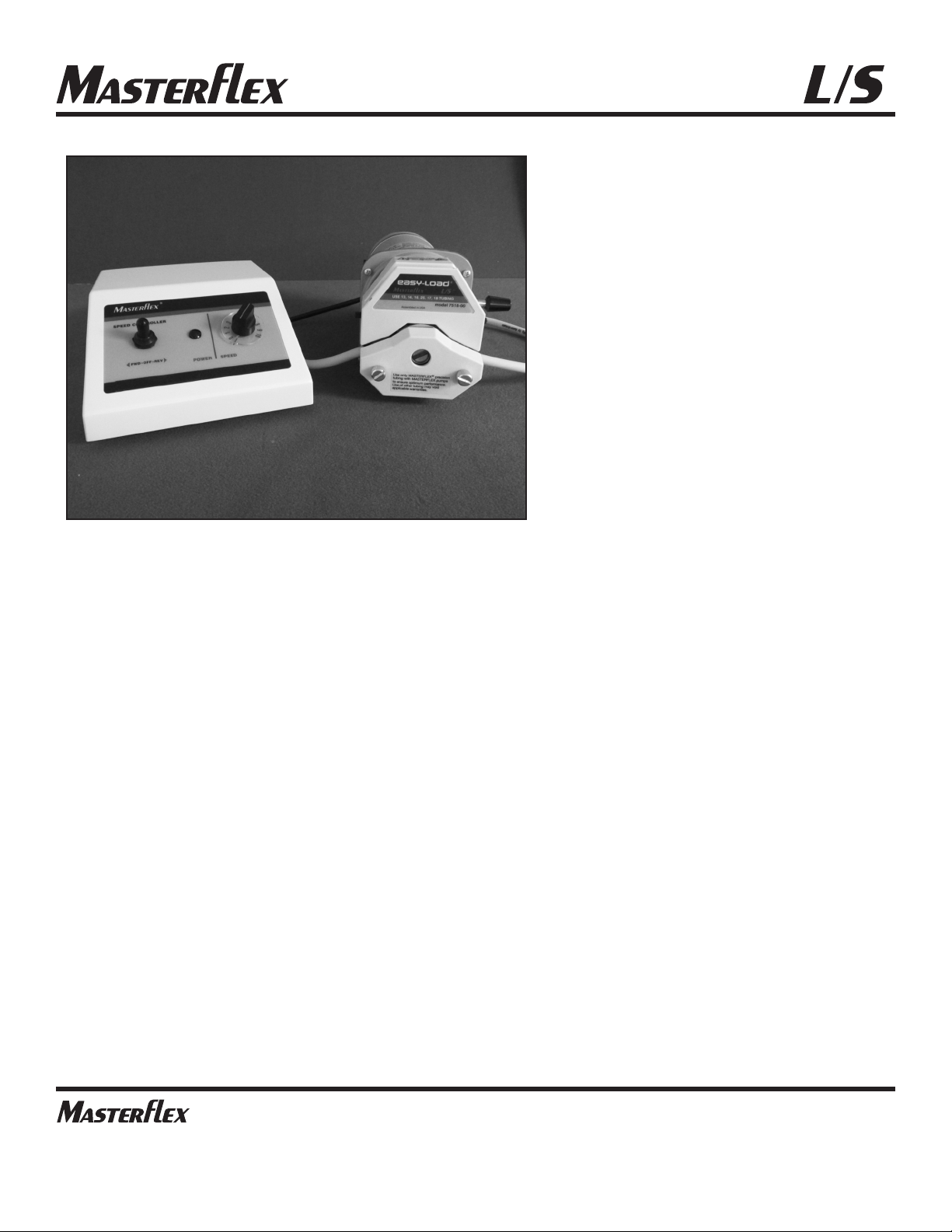
Pump Drive 07559-00 with Pump Head 07516-00
Model Nos.
07559-00
07559-05
07559-10
07559-15
®
®
A12997331
Edition 02
(US & Canada only) Toll Free 1800MASTERFLEX • 18006373739
(Outside US & Canada) 18475497600 • 18473817050
www.masterflex.com • techinfo@masterflex.com
®
Page 2

© 2019 Cole-Parmer Instrument Company. All rights reserved.
Masterflex – Reg TM Cole-Parmer Instrument Company.
Trademarks bearing the ®symbol in this publication are registered in the U.S. and in other countries.
PUMP FOR LIQUIDS
ORIGINAL INSTRUCTIONS
Masterflexii MASTERFLEX L/S Variable-Speed Modular Drives Operating Manual
Page 3
Masterflex MASTERFLEX L/S Variable-Speed Modular Drives Operating Manual iii
DANGER: High voltages exist and are accessible in the
Drive/Controller.
WARNINGS: Disconnect the AC power input line cord before
connecting the drive motor cable.
No user serviceable parts are inside of this controller. Refer servicing
to your dealer.
CAUTIONS: Do not block the rear panel of the pump drive. The power
cord must always be easy to disconnect.
Replace the power cord only with one of the same type and
rating. The minimum power ratings are stated on the rear panel.
CAUTION: Risk of Danger. Consult Operator’s manual for nature of
hazard and corrective actions.
CAUTION: Risk of crushing. Keep fingers away from rotor while
pump is in operation. Stop pump before loading or unloading tubing.
CAUTION: Hot Surface. Do not touch.
CAUTION: Risk of electric shock. Consult Operator’s manual for nature
of hazard and corrective actions.
This product is not designed for, nor intended for use in patient
connected applications; including, but not limited to, medical and
dental use, and accordingly has not been submitted for FDA approval.
This product is not designed for, nor intended for use in
hazardous duty areas as defined by ATEX or the NEC (National
Electrical Code); including, but not limited to use with flammable
liquids. Consult the factory for products suitable for these types of
applications
Preface
Safety Precautions
SAFETY
PRECAUTIONS
Explanation of
Symbols
WARNING:
Product Use
Limitation
Page 4

Page 5

MASTERFLEX L/S Variable-Speed Modular Drives Operating Manual vMasterflex
Table of Contents
Page
INTRODUCTION . . . . . . . . . . . . . . . . . . . . . . . . . . . . . . . . . . . . . . . . . . . . . .1-1
SETUP AND DRIVE OPERATION . . . . . . . . . . . . . . . . . . . . . . . . . . . . . . . .2-1
Before Starting Drive . . . . . . . . . . . . . . . . . . . . . . . . . . . . . . . . . . . . . . . . . . .2-1
Mounting the Pump Head. . . . . . . . . . . . . . . . . . . . . . . . . . . . . . . . . . . . . . . .2-1
MAINTENANCE . . . . . . . . . . . . . . . . . . . . . . . . . . . . . . . . . . . . . . . . . . . . . .3-1
Motor Brush Check/Replacement . . . . . . . . . . . . . . . . . . . . . . . . . . . . . . . . .3-1
Fuse Replacement . . . . . . . . . . . . . . . . . . . . . . . . . . . . . . . . . . . . . . . . . . . . . .3-1
Gear Replacement . . . . . . . . . . . . . . . . . . . . . . . . . . . . . . . . . . . . . . . . . . . . .3-2
Replacement Parts . . . . . . . . . . . . . . . . . . . . . . . . . . . . . . . . . . . . . . . . . . . . .3-2
Cleaning . . . . . . . . . . . . . . . . . . . . . . . . . . . . . . . . . . . . . . . . . . . . . . . . . . . . . .3-2
TROUBLESHOOTING . . . . . . . . . . . . . . . . . . . . . . . . . . . . . . . . . . . . . . . . . .4-1
Troubleshooting Chart . . . . . . . . . . . . . . . . . . . . . . . . . . . . . . . . . . . . . . . . . . .4-1
SPECIFICATIONS . . . . . . . . . . . . . . . . . . . . . . . . . . . . . . . . . . . . . . . . . . . . .5-1
WARRANTY, PRODUCT RETURN, and TECHNICAL ASSISTANCE . . .6-1
Warranty . . . . . . . . . . . . . . . . . . . . . . . . . . . . . . . . . . . . . . . . . . . . . . . . . . . . .6-1
Product Return . . . . . . . . . . . . . . . . . . . . . . . . . . . . . . . . . . . . . . . . . . . . . . . . .6-2
Technical Assistance . . . . . . . . . . . . . . . . . . . . . . . . . . . . . . . . . . . . . . . . . . . .6-2
Section 1
Section 2
Section 3
Section 4
Section 5
Section 6
Page 6

Page 7

Figures
Page
Front View of the Controller . . . . . . . . . . . . . . . . . . . . . . . . . . . . . . . . . . . . . .2-1
Rear View of the Controller . . . . . . . . . . . . . . . . . . . . . . . . . . . . . . . . . . . . . .2-2
Gear Replacement . . . . . . . . . . . . . . . . . . . . . . . . . . . . . . . . . . . . . . . . . . . . . .3-2
MASTERFLEX L/S Variable-Speed Modular Drives Operating Manual viiMasterflex
Figures
Page 8

Page 9

Tables
Page
Replacement Parts . . . . . . . . . . . . . . . . . . . . . . . . . . . . . . . . . . . . . . . . . . . . .3-2
MASTERFLEX L/S Variable-Speed Modular Drives Operating Manual ixMasterflex
Tables
Page 10

Page 11

MASTERFLEX L/S Variable-Speed Modular Drives Operating Manual 1-1Masterflex
Section 1 Introduction
The Drive controls the speed of MASTERFLEX® L/S® Pump Heads to
provide flow rates from 0.006 to 3400 mL/min.
Mount up to 2 (600 rpm) or 4 (100 rpm) MASTERFLEX L/S Pump
Heads and all MASTERFLEX-compatible Pump Heads.
Page 12

Page 13

MASTERFLEX L/S Variable-Speed Modular Drives Operating Manual 2-1Masterflex
Section 2 Setup and Drive Operation
• The drive should be mounted on a flat horizontal surface, and no more
than two (2) Pump Heads should be added for 600 rpm drives or four
(4) Pump Heads for 100 rpm drives.
• The ambient air temperature should not exceed 104° F (40° C) and
adequate air flow should be provided for.
CAUTION: Do not block the rear panel of the pump drive. The
power cord must always be easy to disconnect.
1. Mount pump head and load tubing. (See pump head manual.)
2 Connect the drive motor cable to the receptacle on the rear side of the
controller.
3. Connect the AC power input line cord to the AC receptacle.
4. Selecting motor direction turns pump on.
5. Adjust flow rate with speed control potentiometer.
Before Starting Drive
Mounting the
Pump Head
A
BC
Figure 2-1. Front View of the Controller
A. Forward-Off-Reverse Switch
B. Power On Indicator
C. Speed Control
Page 14

2-2 MASTERFLEX L/S Variable-Speed Modular Drives Operating Manual Masterflex
Section 2
Setup and Drive Operation
Mounting the
Pump Head
(continued)
Figure 2-2. Rear View of the Controller
A. 115V/230V Plug
B. IEC 320 Power Entry Module
C. Replaceable fuse
Page 15

MASTERFLEX L/S Variable-Speed Modular Drives Operating Manual 3-1Masterflex
Section 3 Maintenance
NOTE: Brushes should be checked every 6 months or 2000 operating
hours.
1. Place the FWD-OFF-REV switch in the OFF position.
2. Disconnect the AC line cord from the AC receptacle.
3. Disconnect the drive motor cable from the receptacle on the rear of the
controller.
4. Carefully unscrew each brush holder on opposite sides of the motor.
Withdraw the brush, and examine it for wear.
NOTE: Replace both brushes, if either brush is less than 0.300" long from
base to point.
5. Screw brushes into brush holder on each side of motor.
6. Connect motor to rear panel connector on controller.
7 Connect AC line cord to AC receptacle.
NOTE: 115V units have an internal fuse. Unit must be returned for
servicing.
1. On 230V units, place the FWD-OFF-REV switch in the OFF
position.
2. Disconnect the AC line cord from the rear of the unit.
3. Remove and check the fuse located on the rear panel below the AC
power connector and replace if defective.
4. Reconnect AC line cord.
Motor Brush Check/
Replacement
Fuse Replacement
Page 16

3-2 MASTERFLEX L/S Variable-Speed Modular Drives Operating Manual Masterflex
Section 3
Maintenance
Replacement Parts
Gear Replacement
A
B
C
D
E
F
Figure 3-1. Gear Replacement
Table 3-1. Replacement Parts
A. 6-600 rpm gear assembly (included in service kit 07553-06)
B. Gasket
C. Cap
D. Motor Brush
E. 1-100 rpm gear set (included in service kit 07553-08)
F. Gear Case cover assembly
Model No. 07559-00 07559-05 07559-10 07559-15
Brushes (2/set) 07520-04 07520-04 07520-04 07520-04
Brush Cap Holder 07520-03 07520-03 07520-03 07520-03
Fuses — 77500-11 — 77500-11
High speed gear 07553-09 07553-09 — —
Gear Service kit 07553-06 07553-06 07553-08 07553-08
Motor only 07559-02 07559-07 07559-12 07559-17
Controller only 07559-04 07559-09 07559-04 07559-09
Cleaning
Keep the drive enclosure clean with mild detergents. Do not immerse or
use excessive fluid when cleaning.
Page 17

MASTERFLEX L/S Variable-Speed Modular Drives Operating Manual 4-1Masterflex
Symptom Cause Remedy
Section 4 Troubleshooting
Troubleshooting Chart
Motor does not rotate,
when switched to FWD
or REV. POWER indicator
does not glow.
Motor does not rotate,
when switched to FWD
or REV. Power indicator
glows. Speed control
setting is greater than 0.
Defective line cord or fuse.
Defective Motor or Controller.
1. Check that unit is plugged into
a live line.
2. On 115V and 230V unit, check
line cord for continuity and
replace if defective.
3. On 230V units only, check fuse
and replace if defective.
4 On 115V units, return for
servicing.
1. Place the FWD-OFF-REV switch
in the OFF position.
2. Test motor and controller:
a) Check the drive motor cable
connector on the rear of the
controller and insert the
connector fully into the
controller receptacle.
b) Replace motor, with similar
unit. Reconnect the drive
motor cable connector on
the rear of the controller.
Retest.
c) Replace controller with
similar unit. Reconnect
the drive motor cable to
connector on the rear of
the controller. Retest.
Page 18

Page 19

Section 5 Specifications
Operating Temperature: 0 to 40°C
Storage Temperature: -45° to 65°C
Chemical Resistance: Exposed material is paint, plastic,
aluminum, and vinyl
Pollution Degree: Pollution degree 2 (indoor use–lab, office,
sheltered locations)
Noise Level: 70db or below
Line Voltage Limits: 90–130V or 190–260V, 50-60 Hz
Typical Power:
Motor: 0.075 kW (0.1 hp)
Controller: 6 watts, max. dissipation
Max Current:
115V Units: Controller: 2.2 amps, shorted output
conditions
230V Units: Controller: 1.2 amps, shorted output
conditions
Torque:
600 rpm Units: 13 kg-cm (180 oz-in)
100 rpm Units: 26 kg-cm (360 oz-in)
Speed Regulation: ±1% Line Regulation
±2% Load Regulation
±10% Warm-Up Drift
Controller Enclosure Rating: IP33
Motor Enclosure Rating: IP33
Humidity (non-condensing): 0% to 90%
Display: Green LED
MASTERFLEX L/S Variable-Speed Modular Drives Operating Manual 5-1Masterflex
Page 20

Dimensions: (L × W × H)
Motor: 203 mm × 102 mm × 127 mm
(8 × 4 × 5)
Controller: 178 mm × 127 mm × 88.9 mm
(7 × 5 × 3
11
/42)
Weight:
Motor: 3.6 kg (8 pounds)
Controller: 0.64 kg (1.4 pounds)
Masterflex5-2 MASTERFLEX L/S Variable-Speed Modular Drives Operating Manual
Section 5
Specifications
Page 21

Section 6 Warranty, Product Return and
Technical Assistance
Use only MASTERFLEX precision tubing with MASTERFLEX pumps to
ensure optimum performance. Use of other tubing may void applicable
warranties.
This product is warranted against defects in material or workmanship, and
at the option of the manufacturer or distributor, any defective product will
be repaired or replaced at no charge, or the purchase price will be refunded
to the purchaser, provided that: (a) the warranty claim is made in writing
within the period of time specified on the warranty card, (b) proof of
purchase by bill of sale or receipted invoice is submitted concurrently with
the claim and shows that the product is within the applicable warranty
period, and (c) the purchaser complies with procedures for returns set
forth in the general terms and conditions contained in the manufacturer's
or distributor's most recent catalog.
This warranty shall not apply to: (a) defects or damage resulting from: (i)
misuse of the product, (ii) use of the product in other than its normal and
customary manner, (iii) accident or neglect, (iv) improper testing,
operation, maintenance, service, repair, installation, or storage, (v)
unauthorized alteration or modification, or (b) post-expiration dated
materials.
THIS WARRANTY IS THE EXCLUSIVE REMEDY OF THE
PURCHASER, AND THE MANUFACTURER AND DISTRIBUTOR
DISCLAIM ALL OTHER WARRANTIES, WHETHER EXPRESS,
IMPLIED, OR STATUTORY, INCLUDING WITHOUT
LIMITATION, WARRANTIES OF MERCHANTABILITY AND
FITNESS FOR A PARTICULAR PURPOSE. NO EMPLOYEE,
AGENT, OR REPRESENTATIVE OF THE MANUFACTURER OR
DISTRIBUTOR IS AUTHORIZED TO BIND THE
MANUFACTURER OR DISTRIBUTOR TO ANY OTHER
WARRANTY. IN NO EVENT SHALL THE MANUFACTURER OR
DISTRIBUTOR BE LIABLE FOR INCIDENTAL, INDIRECT,
SPECIAL OR CONSEQUENTIAL DAMAGES.
The warranty period for this product is two (2) years from date of purchase.
MASTERFLEX L/S Variable-Speed Modular Drives Operating Manual 6-1Masterflex
Warranty
Page 22

6-2 MASTERFLEX L/S Variable-Speed Modular Drives Operating Manual Masterflex
Section 6
Warranty, Product Return and
Technical Assistance
To limit charges and delays, contact the Manufacturer or authorized seller for
authorization and shipping instructions before returning the product, either
within or outside of the warranty period. When returning the product, please
state the reason for the return. For your protection, pack the product
carefully and insure it against possible damage or loss. Any damages resulting
from improper packaging are your responsibility.
If you have any questions about the use of this product, contact the
Manufacturer or authorized seller.
Product Return
Technical Assistance
Page 23

Page 24

US & Canada only
Toll Free 1-800-MASTERFLEX | 1-800-637-3739
Outside US & Canada
1-847-549-7600 | 1-847-381-7050
*EN809 manufactured by:
Cole-Parmer Instrument Company
28W092 Commercial Avenue, Barrington, IL 60010
techinfo@masterflex.com | www.masterflex.com
®
®
 Loading...