

Page 1
OPERATING MANUAL:
PUMP DRIVES
Model Nos.
07555-00
07555-05
07555-10
07555-15
®
®
A12991175
Edition 02
(US & Canada only) Toll Free 1800MASTERFLEX • 18006373739
(Outside US & Canada) 18475497600 • 18473817050
www.masterflex.com • techinfo@masterflex.com
®
Page 2

© 2019 Cole-Parmer Instrument Company. All rights reserved.
Masterflex – Reg TM Cole-Parmer Instrument Company.
Trademarks bearing the ®symbol in this publication are registered in the U.S. and in other countries.
PUMP FOR LIQUIDS
ORIGINAL INSTRUCTIONS
Masterflexii Pump Drives Operating Manual
Page 3

WARNINGS: Remove power from the pump before attempting
any maintenance.
Remove power from the pump before any cleaning operation is
started.
Repeatedly applying AC line power to the drive as a means of
starting the pump can cause drive hardware damage and will
void the warranty. Use the control inputs located on the 9 pin
connector to start and stop the pump; this will dramatically
reduce the current surge associated with starting the pump.
Replace the power cord only with one of the same type and
rating. The minimum power ratings are stated on the rear panel.
WARNINGS: Tubing breakage may result in fluid being sprayed
from pump. Use appropriate measures to protect operator and
equipment.
Turn Pump System off before removing or installing tubing.
Fingers or loose clothing could get caught in drive mechanism.
CAUTIONS: When changing flow direction, allow the pump to
come to a complete stop before starting again. Failure to do so
could cause permanent damage to the motor.
Replace the fuse only with one of the same type and rating.
The fuse rating and type are stated on the rear panel.
CAUTIONS: To avoid electrical shock, the power cord
protective grounding conductor must be connected to ground.
Not for operation in wet locations as defined by EN61010-1.
If the product is not used in a manner specified in the
instructions, the protection provided by the equipment may
be impaired.
CAUTION: Risk of Danger. Consult Operator’s manual for nature
of hazard and corrective actions.
CAUTION: Risk of crushing. Keep fingers away from rotor while
pump is in operation. Stop pump before loading or unloading
tubing.
CAUTION: Hot Surface. Do not touch.
CAUTION: Risk of electric shock. Consult Operator’s manual for
nature of hazard and corrective actions.
Masterflex Pump Drives Operating Manual iii
Preface
Safety Precautions
SAFETY
PRECAUTIONS
Explanation of
Symbols
Page 4

iv Pump Drives Operating Manual Masterflex
This product is not designed for, nor intended for use in patient
connected applications; including, but not limited to, medical and
dental use, and accordingly has not been submitted for FDA
approval.
This product is not designed for, nor intended for use in
hazardous duty areas as defined by ATEX or the NEC
(National Electrical Code); including, but not limited to use with
flammable liquids. Consult the factory for products suitable for
these types of applications.
1. Read instructions before operating the unit.
2. Observe safety precautions at all times, especially when pumping
dangerous liquids.
3. If the pump runs unusually noisy or if bunching of the tubing in the
pump can be observed, make sure the tubing is clamped down tightly
and/or replace it with a new piece of tubing.
4. The Pump Drives must be well-grounded at all times.
5. The Pump Drives are equipped with a current-limiting circuit that will
slow the motor down if any of the following conditions exist:
a. Tubing that is too hard is loaded in the pump.
b. Incorrect tubing size or wall thickness is loaded in the pump.
c. Tubing is improperly loaded into the Pump Head.
6. The unit is fused and grounded to protect the operator in the event of
short circuits that could be caused by liquid entering the case.
CAUTION: Replace the fuse only with one of the same type and
rating. The fuse rating and type are stated on the rear panel.
7. The Pump Drives should not be used in outdoor or hazardous
locations.
WARNING:
Product Use
Limitation
Safety
Page 5

Pump Drives Operating Manual vMasterflex
Table of Contents
Page
INTRODUCTION . . . . . . . . . . . . . . . . . . . . . . . . . . . . . . . . . . . . . . . . . . . . . .1-1
Variety of Pump Heads Accepted . . . . . . . . . . . . . . . . . . . . . . . . . . . . . . . . . .1-1
INSTALLATION AND SETUP . . . . . . . . . . . . . . . . . . . . . . . . . . . . . . . . . . .2-1
Setup and Drive Operation . . . . . . . . . . . . . . . . . . . . . . . . . . . . . . . . . . . . . .2-1
External Start/Stop Control . . . . . . . . . . . . . . . . . . . . . . . . . . . . . . . . . . . . . . .2-3
MAINTENANCE . . . . . . . . . . . . . . . . . . . . . . . . . . . . . . . . . . . . . . . . . . . . . .3-1
Motor Brush Check/Replacement . . . . . . . . . . . . . . . . . . . . . . . . . . . . . . . . . .3-1
Motor Gear and Brush Replacement . . . . . . . . . . . . . . . . . . . . . . . . . . . . . . .3-2
Fuse Replacement . . . . . . . . . . . . . . . . . . . . . . . . . . . . . . . . . . . . . . . . . . . . . .3-3
Replacement Parts . . . . . . . . . . . . . . . . . . . . . . . . . . . . . . . . . . . . . . . . . . . . .3-4
Cleaning . . . . . . . . . . . . . . . . . . . . . . . . . . . . . . . . . . . . . . . . . . . . . . . . . . . . . .3-4
ACCESSORIES . . . . . . . . . . . . . . . . . . . . . . . . . . . . . . . . . . . . . . . . . . . . . . .4-1
SPECIFICATIONS . . . . . . . . . . . . . . . . . . . . . . . . . . . . . . . . . . . . . . . . . . . . .5-1
WARRANTY, PRODUCT RETURN, and TECHNICAL ASSISTANCE . . .6-1
Warranty . . . . . . . . . . . . . . . . . . . . . . . . . . . . . . . . . . . . . . . . . . . . . . . . . . . . .6-1
Product Return . . . . . . . . . . . . . . . . . . . . . . . . . . . . . . . . . . . . . . . . . . . . . . . . .6-2
Technical Assistance . . . . . . . . . . . . . . . . . . . . . . . . . . . . . . . . . . . . . . . . . . . .6-2
Section 1
Section 2
Section 3
Section 6
Section 4
Section 5
Page 6

Figures
Page
View of Rear Drive . . . . . . . . . . . . . . . . . . . . . . . . . . . . . . . . . . . . . . . . . . . . .2-2
View of Drive Front Controls . . . . . . . . . . . . . . . . . . . . . . . . . . . . . . . . . . . . . .2-2
DB-9 Pin Connector Configuration with Wiring Scheme . . . . . . . . . . . . . . . .2-3
DB-9 Pin Connector Jumper Installation . . . . . . . . . . . . . . . . . . . . . . . . . . . .2-3
Motor Brush and Gear Check/Replacement . . . . . . . . . . . . . . . . . . . . . . . . . .3-2
Fuse Replacement . . . . . . . . . . . . . . . . . . . . . . . . . . . . . . . . . . . . . . . . . . . . . .3-3
vi Pump Drives Operating Manual Masterflex
Figures
Page 7

Pump Drives Operating Manual 1-1Masterflex
Section 1 Introduction
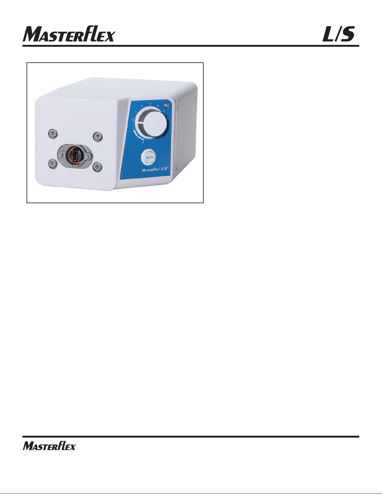
Mount up to 1 (600 rpm) or 2 (200 rpm) MASTERFLEX® L/S® Pump
Heads and all MASTERFLEX-compatible Pump Heads.
Variety of Pump
Heads Accepted
Page 8

2-1 Pump Drives Operating Manual Masterflex
Section 2 Installation and Setup
WARNINGS: Tubing breakage may result in fluid being sprayed
from pump. Use appropriate measures to protect operator and
equipment.
Turn Pump System off before removing or installing tubing.
Fingers or loose clothing could get caught in drive mechanism.
1. Mount Pump Head and load tubing. (See Pump Head manual.)
CAUTION: To avoid electrical shock, the power cord
protective grounding conductor must be connected to ground. Not
for operation in wet locations as defined by EN61010-1.
2.
Check that the jumper is installed in the external start/stop connector
.
The drive will not run unless this is installed See figure 2-3.
3. Adjust flow rate with the 1-turn potentiometer speed control.
CAUTION: When changing flow direction, allow the pump to
come to a complete stop before starting again. Failure to do so
could cause permanent damage to the motor.
Setup and Drive
Operation
Page 9
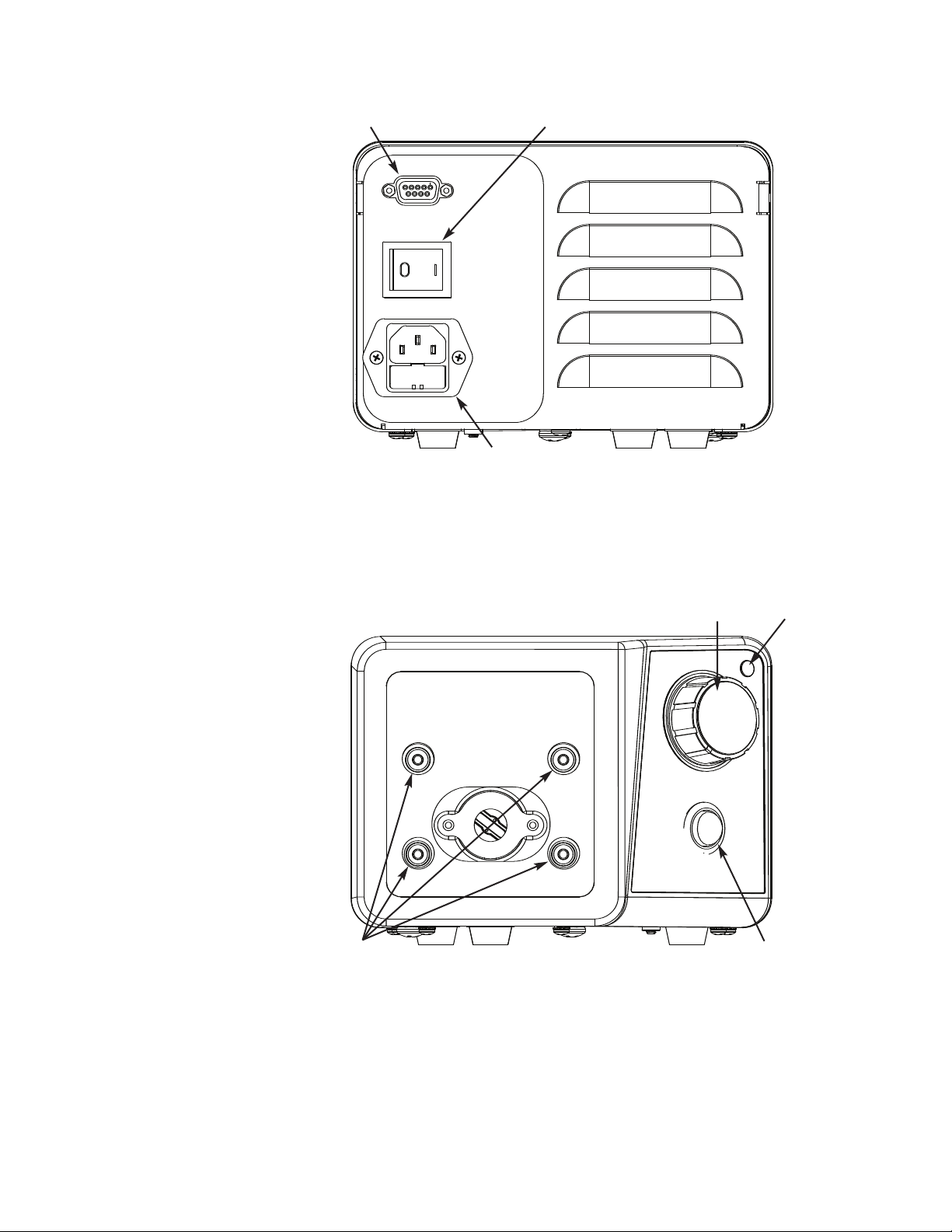
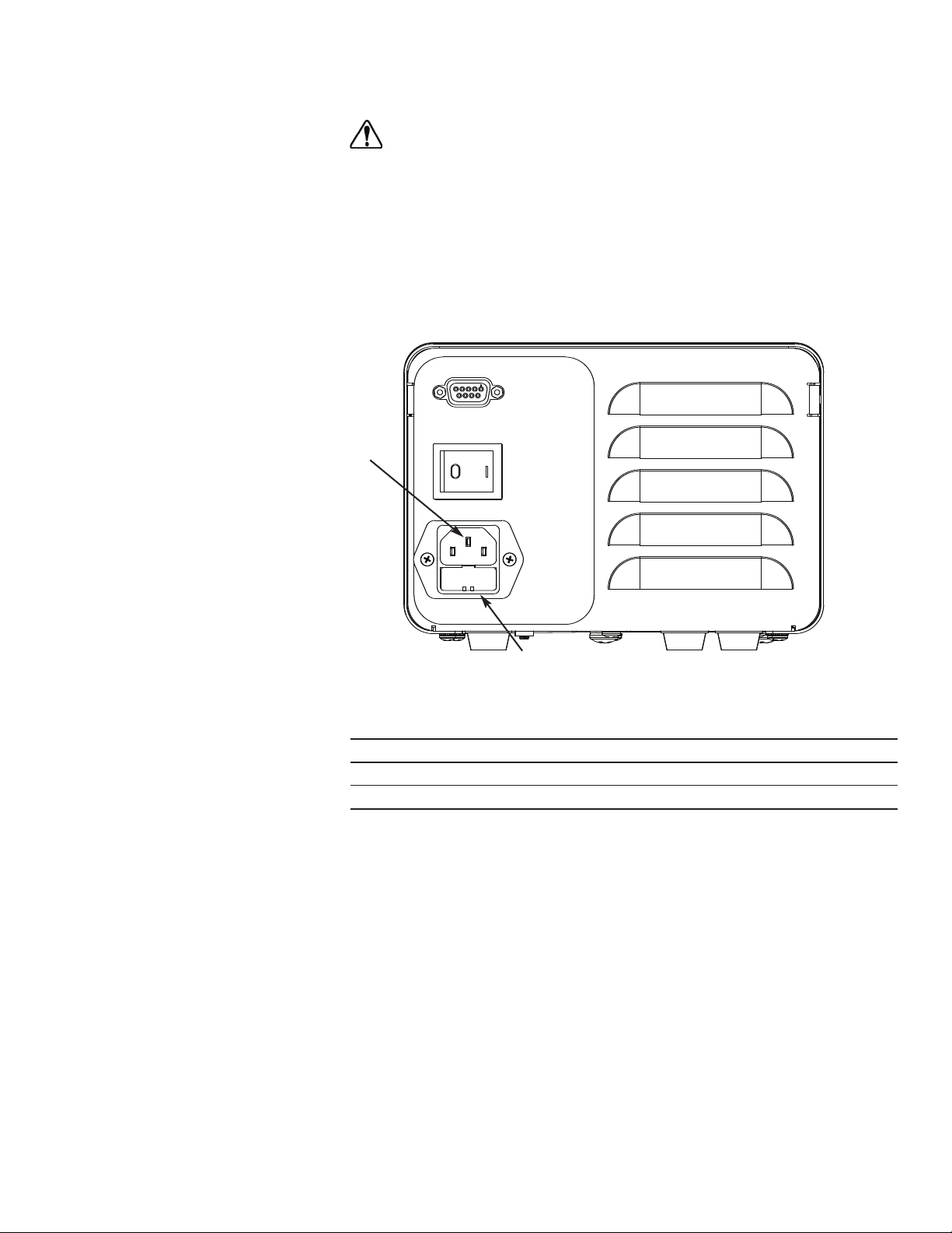
A. IEC Power Entry module
B. Power Switch
C. External Start/Stop Connector
Figure 2-1. View of Rear Drive
Pump Drives Operating Manual 2-2Masterflex
Section 2
Installation and Setup
A. Pump Head Mounting Holes
B. 1-Turn Speed Control
C. Power Indicator
D. Direction Switch
Figure 2-2. View of Drive Front Controls
A
B
C
A
B
C
D
Page 10
2-3 Pump Drives Operating Manual Masterflex
External Start/Stop
Control
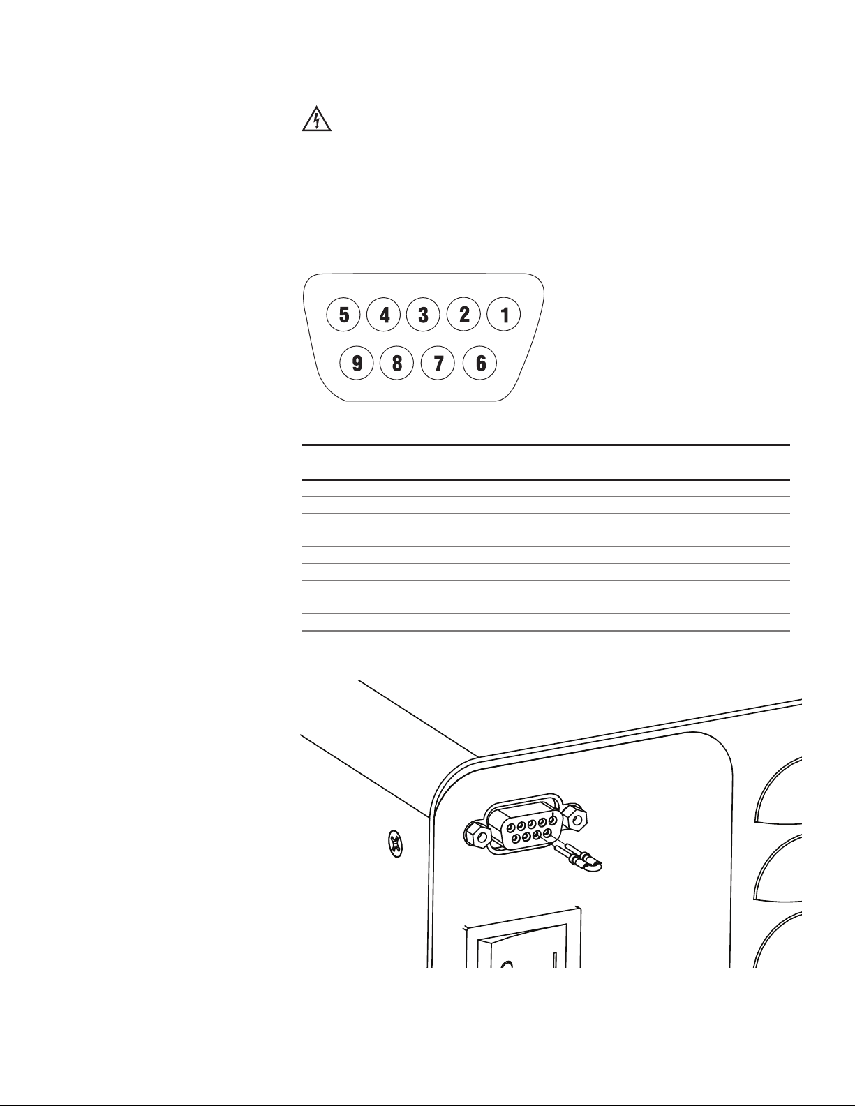
WARNING: Repeatedly applying AC line power to the drive as
a means of starting the pump can cause drive hardware damage
and will void the warranty. Use the control inputs located on the
9 pin connector to start and stop the pump; this will dramatically
reduce the current surge associated with starting the pump.
Replace the power cord only with one of the same type and
rating. The minimum power ratings are stated on the rear panel.
Figure 2-3. DB-9 Pin Connector Configuration with Wiring Scheme
Pin No. Description
DB-9
1
2
3
4
5
6 Start/Stop
7 Start/Stop
8
9
NOTE:
Jumper must be installed for pump to run.
Figure 2-4. DB-9 Pin Connector Jumper Installation.
Section 2
Installation and Setup
Page 11

Pump Drives Operating Manual 3-1Masterflex
Section 3 Maintenance
Motor Brush
Check/Replacement
WARNING: Remove power from the pump before attempting any
maintenance.
1. Place the ON/OFF SWITCH in the off position.
2. Disconnect the AC power input line cord from the AC receptacle.
3. Remove the screws from each side of the housing and lift off the
housing.
4. Carefully unscrew each brush cap. Withdraw the brush, and examine it
for wear.
NOTE:
Replace both brushes, if either brush is less than 7.6 mm (0.300 in)
long from base to point.
5. Insert brushes and install brush cap.
6. Install housing and secure with the screws on each side.
7. Connect the AC power input line cord to the AC receptacle.
Page 12
3-2 Pump Drives Operating Manual Masterflex
Section 3
Maintenance
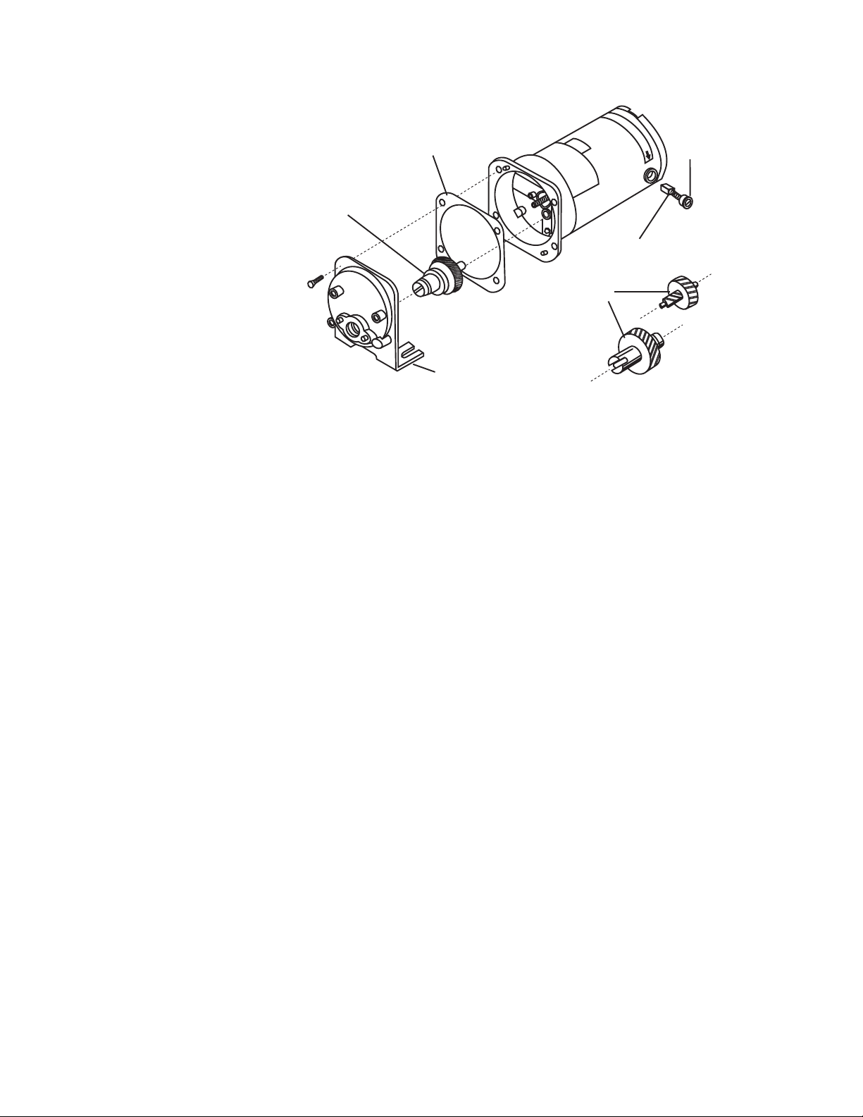
A. 20-600 rpm gear assembly (included in service kit 07553-06)
B. Gasket
C. Cap
D. Motor Brush
E. 7-200 rpm gear set (included in service kit 07553-11)
F. Gear case cover assembly
Figure 3-1. Motor Brush and Gear Check/Replacement.
Motor Gear and Brush
Replacement
A
B
C
D
E
F
Page 13
CAUTION: Replace the fuse only with one of the same type and
rating. The fuse rating and type are stated on the rear panel.
1. Place the power switch in the off position.
2. Disconnect the AC power input line cord from the receptacle.
3. Remove and check the fuse and replace if defective..
Figure 3-2. Fuse Replacement
Item Description
A IEC Power Entry Module / Line Cord
B (5 x 20 mm) Fuse – Do Not Substitute
Pump Drives Operating Manual 3-3Masterflex
Section 3
Maintenance
Fuse Replacement
A
B
Page 14

3-4 Pump Drives Operating Manual Masterflex
Section 3
Maintenance
Replacement Parts
Description Part Number
Gear Service Kit (600 rpm) 07553-06
Gear Only (600 rpm) 07553-09
Gear Service Kit (200 rpm) 07553-11
Brushes (set of 2) 07520-06
Jumper Kit (set of 2) 07555-90
Fuse (07555-05, 15) T1.0A 250V; 4 × 20 mm 77500-58
Fuse (07555-00, -10) T2.0A 250V; 5 × 20 mm 07555-92
Cleaning
WARNING:
Remove power from the pump before any cleaning
operation is started.
Keep the drive enclosure clean with mild detergents. Do not immerse or
use excessive fluid when cleaning.
Page 15

Pump Drives Operating Manual 4-1Masterflex
Section 4 Accessories
Description Part Number
Footswitch with 6 ft. DB-9 male connector 77595-35
Handheld Remote Controller 07528-80
DB-9 External Control Connector 07595-45
DB-9 Remote Control Cable, 25 ft. 07595-47
Page 16

Section 5 Specifications
Output:
Speed:
600 rpm models 20 to 600 rpm
200 rpm models 7 to 200 rpm
Torque output, Maximum:
600 rpm models 90 oz-in (13 kg•cm), 270 oz-in Starting
200 rpm models 180 oz-in (26 kg•cm), 540 oz-in Starting
Speed regulation:
All models Line ±2% F.S.
Load ±3% F.S.
Drift ±10% F.S.
Input:
Operating Voltage/Frequency: 1.4A @ 115 Vrms 50/60 Hz,
0.7A @ 230 Vrms 50/60 Hz
External Inputs:
START/STOP Dry Contact closure
Construction:
Dimensions (L x W x H): 9.09 in x 7.23 in x 5.29 in
(231 × 184 × 134.5 mm)
Weight: 9.46 lbs. (4.26 kg)
Enclosure Rating: IP 22 per IEC 60529
5-1 Pump Drives Operating Manual Masterflex
Page 17

Environment:
Temperature, Operating:
All models 0° to 40°C (32° to 104°F)
Temperature, Storage:
All models –25° to 65°C (–13° to 149°F)
Humidity (non-condensing):
All models 10% to 90%
Altitude:
All models Less than 2000 m
Pollution Degree:
All models Pollution Degree 3
(Indoor use -- Sheltered locations)
Chemical Resistance: Powder coated steel enclosure and
cover, ABS plastic and vinyl
Compliance: Certified to ANSI/UL
61010-1 3rd Edition
and CSA C22.2
No. 61010-1-12
(For CE Mark):
EN61010-1 (EU Low Voltage Directive)
and EN61326-1 (EU EMC Directive)
5-1 Pump Drives Operating Manual 5-2Masterflex
Section 5
Specifications
Page 18

Section 6 Warranty, Product Return and
Technical Assistance
Use only MASTERFLEX precision tubing with MASTERFLEX pumps to
ensure optimum performance. Use of other tubing may void applicable
warranties.
This product is warranted against defects in material or workmanship, and
at the option of the manufacturer or distributor, any defective product will
be repaired or replaced at no charge, or the purchase price will be refunded
to the purchaser, provided that: (a) the warranty claim is made in writing
within the period of time specified on the warranty card, (b) proof of
purchase by bill of sale or receipted invoice is submitted concurrently with
the claim and shows that the product is within the applicable warranty
period, and (c) the purchaser complies with procedures for returns set
forth in the general terms and conditions contained in the manufacturer's
or distributor's most recent catalog.
This warranty shall not apply to: (a) defects or damage resulting from: (i)
misuse of the product, (ii) use of the product in other than its normal and
customary manner, (iii) accident or neglect, (iv) improper testing,
operation, maintenance, service, repair, installation, or storage, (v)
unauthorized alteration or modification, or (b) post-expiration dated
materials.
THIS WARRANTY IS THE EXCLUSIVE REMEDY OF THE
PURCHASER, AND THE MANUFACTURER AND DISTRIBUTOR
DISCLAIM ALL OTHER WARRANTIES, WHETHER EXPRESS,
IMPLIED, OR STATUTORY, INCLUDING WITHOUT
LIMITATION, WARRANTIES OF MERCHANTABILITY AND
FITNESS FOR A PARTICULAR PURPOSE. NO EMPLOYEE,
AGENT, OR REPRESENTATIVE OF THE MANUFACTURER OR
DISTRIBUTOR IS AUTHORIZED TO BIND THE
MANUFACTURER OR DISTRIBUTOR TO ANY OTHER
WARRANTY. IN NO EVENT SHALL THE MANUFACTURER OR
DISTRIBUTOR BE LIABLE FOR INCIDENTAL, INDIRECT,
SPECIAL OR CONSEQUENTIAL DAMAGES.
The warranty period for this product is two (2) years from date of purchase.
6-1 Pump Drives Operating Manual Masterflex
Warranty
Page 19

To limit charges and delays, contact the Manufacturer or authorized seller
for authorization and shipping instructions before returning the product,
either within or outside of the warranty period. When returning the
product, please state the reason for the return. For your protection, pack
the product carefully and insure it against possible damage or loss. Any
damages resulting from improper packaging are your responsibility.
If you have any questions about the use of this product, contact the
Manufacturer or authorized seller.
Pump Drives Operating Manual 6-2Masterflex
Section 6
Warranty, Product Return and
Technical Assistance
Product Return
Technical Assistance
Page 20

US & Canada only
Toll Free 1-800-MASTERFLEX | 1-800-637-3739
Outside US & Canada
1-847-549-7600 | 1-847-381-7050
*EN809 manufactured by:
Cole-Parmer Instrument Company
28W092 Commercial Avenue, Barrington, IL 60010
techinfo@masterflex.com | www.masterflex.com
®
®
 Loading...