

Page 1
OPERATING MANUAL:
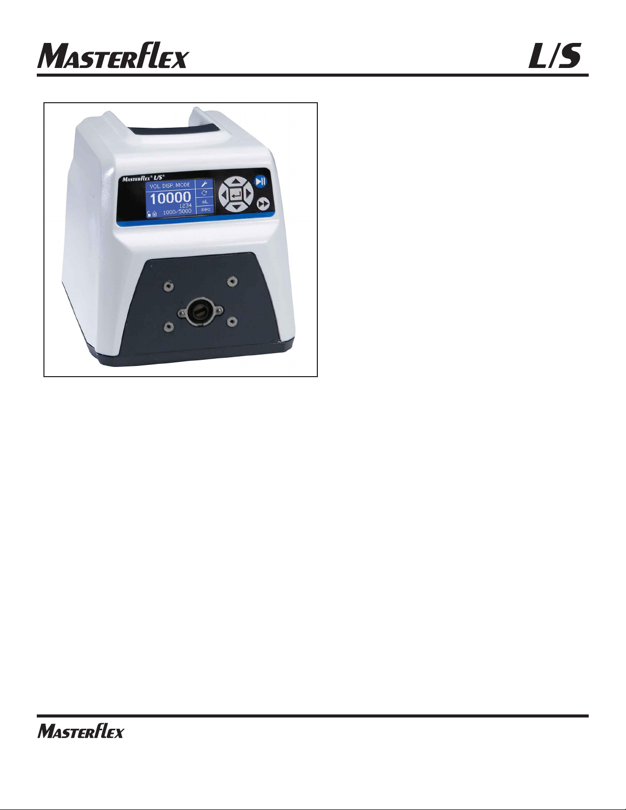
L/S®DIGITAL PUMP
DRIVES
MASTERFLEX®L/S®07528-10
Model Nos.
07522-20
07522-30
07551-20
07551-30
07575-30
07575-40
®
®
A12991127B
Edition 03
(US & Canada only) Toll Free 1800MASTERFLEX • 18006373739
(Outside US & Canada) 18475497600 • 18473817050
www.masterflex.com • techinfo@masterflex.com
®
Page 2

© 2019 Cole-Parmer Instrument Company. All rights reserved.
Masterflex – Reg TM Cole-Parmer Instrument Company.
Trademarks bearing the ®symbol in this publication are registered in the U.S. and in other countries.
PUMP FOR LIQUIDS
ORIGINAL INSTRUCTIONS
Masterflexii MASTERFLEX®L/S Digital Pump Drive Operating Manual
Page 3
Masterflex MASTERFLEX®L/S Digital Pump Drive Operating Manual iii
DANGER: High voltages exist and are accessible. Use extreme caution
when servicing internal components.
WARNINGS: Tubing breakage may result in fluid being sprayed from
pump. Use appropriate measures to protect operator and equipment.
Turn drive off before removing or installing tubing. Fingers or loose
clothing could get caught in drive mechanism.
WARNINGS: Do not operate the pump drive in a manner not
specified in the documentation. Misuse of the pump drive may result in
a hazard and may compromise the safety protection built into the pump
drive. If the pump drive is damaged, turn it off and not use it until service-trained personnel can check its safety.
Single-Phase Only. Not to be used with Split-Phase lines.
The Power switch on the Back Panel is not the main disconnect. Main
disconnect is accomplished by disconnecting the detachable power
supply cord at the appliance coupler or at the main plug. Ensure the
power cord is easily accessible and removable, in the event of an emergency, which requires immediate disconnection.
The operator should check the detachable power supply cord condition. The equipment should not be operated if the power supply cord is
cracked or broken. Any obvious damage to the enclosure (from a drop
or fall) should be checked by service personnel for loose or damaged
parts inside.
CAUTIONS: Power must be turned off before connecting the external
remote control cable to prevent damage to the drive.
Do not contaminate the lubricant in the container, on the shaft or on the
seal with foreign material.
Failure to observe this precaution may result in damage to the seal and
premature failure of the seal.
No foreign matter should be allowed under the gasket on the back of
the front plate or under the heads of the screws.
Failure to observe this precaution may result in leakage during washdown of the drive
Do not block the rear panel of the pump drive. The power switch must
always be easy to access. The power cord must always be easy to disconnect.
Replace the power cord only with one of the same type and
rating. The minimum power ratings are stated on the rear panel.
The power cord set supplied with your pump drive meets the requirements of the country where you purchased the pump drive. If you use
the pump drive in another country, you must use a power cord set that
meets the requirements of that country.
When using hazardous chemical and biological agents, take all suitable protective measures, such as wearing protective glasses and
gloves resistant to the substances used. Follow local and/or national
regulations for safe operation and maintenance of the system.
Preface
Safety Precautions
SAFETY
PRECAUTIONS
Page 4
iv MASTERFLEX®L/S Digital Pump Drive Operating Manual
CAUTION: To avoid electrical shock, the power cord protective
grounding conductor must be connected to ground. Not for
operation in wet locations as defined by EN61010-1.
CAUTIONS: Keep fingers away from rotor while pump is in operation. Stop pump before loading or unloading tubing.
To reduce the possibility of tipping, use the stacking clip
provided with the unit.
CAUTION: Risk of Danger. Consult Operator’s manual for nature of hazard and corrective actions.
CAUTION: Risk of crushing. Keep fingers away from rotor while
pump is in operation. Stop pump before loading or unloading tubing.
CAUTION: Hot Surface. Do not touch.
CAUTION: Risk of electric shock. Consult Operator’s manual for nature
of hazard and corrective actions.
This product is not designed for, nor intended for use in patient connected applications; including, but not limited to, medical and dental
use, and accordingly has not been submitted for FDA approval.
This product is not designed for, nor intended for use in
hazardous duty areas as defined by ATEX or the NEC (National
Electrical Code); including, but not limited to use with flammable liquids. Consult the factory for products suitable for these types of applications
Preface
Safety Precautions
Explanation of
Symbols
WARNING:
Product Use
Limitation
SAFETY
PRECAUTIONS
(continued)
Masterflex
Page 5

MASTERFLEX®L/S Digital Pump Drive Operating Manual vMasterflex
Table of Contents
Page
INTRODUCTION . . . . . . . . . . . . . . . . . . . . . . . . . . . . . . . . . . . . . . . . . . . . . .1-1
Application Solutions . . . . . . . . . . . . . . . . . . . . . . . . . . . . . . . . . . . . . . . . . . .1-1
General Description . . . . . . . . . . . . . . . . . . . . . . . . . . . . . . . . . . . . . . . . . . . . .1-2
INSTALLATION AND SETUP . . . . . . . . . . . . . . . . . . . . . . . . . . . . . . . . . . .2-1
Before Starting the Drive . . . . . . . . . . . . . . . . . . . . . . . . . . . . . . . . . . . . . . . .2-1
Mounting the Pump Head. . . . . . . . . . . . . . . . . . . . . . . . . . . . . . . . . . . . . . . .2-2
OPERATION . . . . . . . . . . . . . . . . . . . . . . . . . . . . . . . . . . . . . . . . . . . . . . . . .3-1
Turning On the Drive . . . . . . . . . . . . . . . . . . . . . . . . . . . . . . . . . . . . . . . . . . . .3-1
Control Panel . . . . . . . . . . . . . . . . . . . . . . . . . . . . . . . . . . . . . . . . . . . . . . . . . .3-2
Priming the Pump . . . . . . . . . . . . . . . . . . . . . . . . . . . . . . . . . . . . . . . . . . . . . .3-2
Main Menu . . . . . . . . . . . . . . . . . . . . . . . . . . . . . . . . . . . . . . . . . . . . . . . . . . .3-3
Tubing Calibration . . . . . . . . . . . . . . . . . . . . . . . . . . . . . . . . . . . . . . . . . . . . . .3-4
Setup Menu . . . . . . . . . . . . . . . . . . . . . . . . . . . . . . . . . . . . . . . . . . . . . . . . . . .3-6
Continuous Mode Screen . . . . . . . . . . . . . . . . . . . . . . . . . . . . . . . . . . . . . . . .3-7
Continuous Mode Operation . . . . . . . . . . . . . . . . . . . . . . . . . . . . . . . . . . . . . .3-8
Time Dispense Mode Screen . . . . . . . . . . . . . . . . . . . . . . . . . . . . . . . . . . . . .3-9
Time Dispense Mode Operation . . . . . . . . . . . . . . . . . . . . . . . . . . . . . . . . . .3-10
Copy Dispense Mode Screen . . . . . . . . . . . . . . . . . . . . . . . . . . . . . . . . . . . .3-12
Copy Dispense Mode Operation . . . . . . . . . . . . . . . . . . . . . . . . . . . . . . . . . .3-13
COPY Setting Screen . . . . . . . . . . . . . . . . . . . . . . . . . . . . . . . . . . . . . . . . . . .3-15
COPY Setting Operation . . . . . . . . . . . . . . . . . . . . . . . . . . . . . . . . . . . . . . . .3-16
Volume Dispense Mode Screen . . . . . . . . . . . . . . . . . . . . . . . . . . . . . . . . . .3-17
Volume Dispense Mode Operation . . . . . . . . . . . . . . . . . . . . . . . . . . . . . . . .3-18
Remote Control Menu . . . . . . . . . . . . . . . . . . . . . . . . . . . . . . . . . . . . . . . . . .3-20
DB-25 Pin Configuration with Wiring Scheme . . . . . . . . . . . . . . . . . . . . . . .3-23
31-Pin Configuration with Wiring Scheme . . . . . . . . . . . . . . . . . . . . . . . . . .3-24
Remote Control Inputs and Outputs . . . . . . . . . . . . . . . . . . . . . . . . . . . . . . .3-25
Open Collector Outputs . . . . . . . . . . . . . . . . . . . . . . . . . . . . . . . . . . . . . . . . .3-26
Anti-Drip Function . . . . . . . . . . . . . . . . . . . . . . . . . . . . . . . . . . . . . . . . . . . . .3-27
Serial Communication Specification . . . . . . . . . . . . . . . . . . . . . . . . . . . . . . .3-28
Linkable Instrument Network . . . . . . . . . . . . . . . . . . . . . . . . . . . . . . . . . . . .3-28
Drives . . . . . . . . . . . . . . . . . . . . . . . . . . . . . . . . . . . . . . . . . . . . . . . . . . . . . . .3-28
USB . . . . . . . . . . . . . . . . . . . . . . . . . . . . . . . . . . . . . . . . . . . . . . . . . . . . . . . .3-28
Section 1
Section 2
Section 3
Page 6

vi MASTERFLEX®L/S Digital Pump Drive Operating Manual Masterflex
Table of Contents
(continued)
Table of Contents
Page
Serial Connections . . . . . . . . . . . . . . . . . . . . . . . . . . . . . . . . . . . . . . . . . . . .3-29
Serial Data Format . . . . . . . . . . . . . . . . . . . . . . . . . . . . . . . . . . . . . . . . . . . .3-30
Serial Protocol . . . . . . . . . . . . . . . . . . . . . . . . . . . . . . . . . . . . . . . . . . . . . . . .3-30
Start-Up Sequence . . . . . . . . . . . . . . . . . . . . . . . . . . . . . . . . . . . . . . . . . . . .3-30
Remote/Local Operation . . . . . . . . . . . . . . . . . . . . . . . . . . . . . . . . . . . . . . . .3-31
Command Format . . . . . . . . . . . . . . . . . . . . . . . . . . . . . . . . . . . . . . . . . . . . .3-32
Control Computer Parameter Fields . . . . . . . . . . . . . . . . . . . . . . . . . . . . . . .3-33
Pump Drive Status Request . . . . . . . . . . . . . . . . . . . . . . . . . . . . . . . . . . . . .3-33
Satellite Response . . . . . . . . . . . . . . . . . . . . . . . . . . . . . . . . . . . . . . . . . . . .3-34
Error Handling . . . . . . . . . . . . . . . . . . . . . . . . . . . . . . . . . . . . . . . . . . . . . . . .3-34
Satellite Request to Send . . . . . . . . . . . . . . . . . . . . . . . . . . . . . . . . . . . . . . .3-35
Front Panel Switches . . . . . . . . . . . . . . . . . . . . . . . . . . . . . . . . . . . . . . . . . .3-38
ASCII Control Codes Used . . . . . . . . . . . . . . . . . . . . . . . . . . . . . . . . . . . . . . .3-38
MAINTENANCE . . . . . . . . . . . . . . . . . . . . . . . . . . . . . . . . . . . . . . . . . . . . . .4-1
Replacement Parts and Accessories . . . . . . . . . . . . . . . . . . . . . . . . . . . . . . . .4-1
Fuse Replacement . . . . . . . . . . . . . . . . . . . . . . . . . . . . . . . . . . . . . . . . . . . . . .4-2
Gear Replacement . . . . . . . . . . . . . . . . . . . . . . . . . . . . . . . . . . . . . . . . . . . . . .4-3
Shaft Seal Inspection (Stainless Steel and Powder Coated Steel
Enclosures Only) . . . . . . . . . . . . . . . . . . . . . . . . . . . . . . . . . . . . . . . . . . . . . . .4-3
Cleaning . . . . . . . . . . . . . . . . . . . . . . . . . . . . . . . . . . . . . . . . . . . . . . . . . . . . . .4-4
TROUBLESHOOTING . . . . . . . . . . . . . . . . . . . . . . . . . . . . . . . . . . . . . . . . . .5-1
Troubleshooting Chart . . . . . . . . . . . . . . . . . . . . . . . . . . . . . . . . . . . . . . . . . . .5-1
Error Definitions . . . . . . . . . . . . . . . . . . . . . . . . . . . . . . . . . . . . . . . . . . . . . . .5-2
ACCESSORIES . . . . . . . . . . . . . . . . . . . . . . . . . . . . . . . . . . . . . . . . . . . . . . .6-1
SPECIFICATIONS . . . . . . . . . . . . . . . . . . . . . . . . . . . . . . . . . . . . . . . . . . . . .7-1
WARRANTY, PRODUCT RETURN, and TECHNICAL ASSISTANCE . . .8-1
Warranty . . . . . . . . . . . . . . . . . . . . . . . . . . . . . . . . . . . . . . . . . . . . . . . . . . . . .8-1
Product Return . . . . . . . . . . . . . . . . . . . . . . . . . . . . . . . . . . . . . . . . . . . . . . . . .8-2
Technical Assistance . . . . . . . . . . . . . . . . . . . . . . . . . . . . . . . . . . . . . . . . . . . .8-2
Section 6
Section 8
Section 7
Section 3 (continued)
Section 4
Section 5
Page 7

Figures
Page
Control Panel . . . . . . . . . . . . . . . . . . . . . . . . . . . . . . . . . . . . . . . . . . . . . . . . . .3-2
Continuous Mode Screen . . . . . . . . . . . . . . . . . . . . . . . . . . . . . . . . . . . . . . . .3-7
Continuous Mode Operation . . . . . . . . . . . . . . . . . . . . . . . . . . . . . . . . . . . . . .3-8
Time Dispense Mode Screen . . . . . . . . . . . . . . . . . . . . . . . . . . . . . . . . . . . . .3-9
Time Dispense Mode Operation . . . . . . . . . . . . . . . . . . . . . . . . . . . . . . . . . .3-10
Copy Dispense Mode Screen . . . . . . . . . . . . . . . . . . . . . . . . . . . . . . . . . . . .3-12
Copy Dispense Mode Operation . . . . . . . . . . . . . . . . . . . . . . . . . . . . . . . . . .3-13
COPY Setting Screen . . . . . . . . . . . . . . . . . . . . . . . . . . . . . . . . . . . . . . . . . . .3-15
COPY Setting Operation . . . . . . . . . . . . . . . . . . . . . . . . . . . . . . . . . . . . . . . .3-16
Volume Dispense Mode Screen . . . . . . . . . . . . . . . . . . . . . . . . . . . . . . . . . .3-17
Volume Dispense Mode Operation . . . . . . . . . . . . . . . . . . . . . . . . . . . . . . . .3-18
Remote Control Menu Screen . . . . . . . . . . . . . . . . . . . . . . . . . . . . . . . . . . . .3-20
DB-25 Pin Configuration with Wiring Scheme . . . . . . . . . . . . . . . . . . . . . . .3-23
31-Pin Configuration with Wiring Scheme . . . . . . . . . . . . . . . . . . . . . . . . . .3-24
Terminating Open Collector Outputs to a PLC . . . . . . . . . . . . . . . . . . . . . . .3-26
Anti-Drip Screen . . . . . . . . . . . . . . . . . . . . . . . . . . . . . . . . . . . . . . . . . . . . . .3-27
Anti-Drip Degrees Screen . . . . . . . . . . . . . . . . . . . . . . . . . . . . . . . . . . . . . . .3-27
Serial Daisy-Chain Connection . . . . . . . . . . . . . . . . . . . . . . . . . . . . . . . . . . .3-29
Command Format . . . . . . . . . . . . . . . . . . . . . . . . . . . . . . . . . . . . . . . . . . . . .3-32
Parameter Fields . . . . . . . . . . . . . . . . . . . . . . . . . . . . . . . . . . . . . . . . . . . . . .3-33
Fuse Replacement . . . . . . . . . . . . . . . . . . . . . . . . . . . . . . . . . . . . . . . . . . . . . .4-2
Motor . . . . . . . . . . . . . . . . . . . . . . . . . . . . . . . . . . . . . . . . . . . . . . . . . . . . . . . .4-3
Shaft Seal Inspection . . . . . . . . . . . . . . . . . . . . . . . . . . . . . . . . . . . . . . . . . . .4-3
MASTERFLEX®L/S Digital Pump Drive Operating Manual viiMasterflex
Figures
Page 8

Page 9

Tables
Page
Continuous Mode Operation . . . . . . . . . . . . . . . . . . . . . . . . . . . . . . . . . . . . .3-22
Dispense Mode Operation . . . . . . . . . . . . . . . . . . . . . . . . . . . . . . . . . . . . . .3-22
Remote Control Inputs and Outputs . . . . . . . . . . . . . . . . . . . . . . . . . . . . . . .3-25
Pump Satellite Commands . . . . . . . . . . . . . . . . . . . . . . . . . . . . . . . . . . . . . .3-36
Sample Pump Commands and Responses . . . . . . . . . . . . . . . . . . . . . . . . . .3-37
K command key codes for pump drives . . . . . . . . . . . . . . . . . . . . . . . . . . . .3-38
ASCII control codes used . . . . . . . . . . . . . . . . . . . . . . . . . . . . . . . . . . . . . . .3-38
MASTERFLEX®L/S Digital Pump Drive Operating Manual ixMasterflex
Tables
Page 10

Page 11

MASTERFLEX®L/S Digital Pump Drive Operating Manual 1-1Masterflex
Application Solutions
Section 1 Introduction
The Digital drive controls the speed of MASTERFLEX® Pump Heads to
provide flow rates from 0.001 to 3400 mL/min.
Mount up to 2 (600 rpm) or 4 (100 rpm) MASTERFLEX Pump Heads
and all MASTERFLEX-compatible Pump Heads.
Advantages of Peristaltic Pumps:
• Handle abrasive slurries and corrosive fluids with minimal wear. Ideal
for titanium dioxide or diatomaceous earth filter aid applications.
• No seals in contact with the medium pumped.
• No valves to clog.
• Inner surfaces are smooth and easy to clean.
• Fluid contacts only the tubing or tube material.
• Suction lift and priming up to 8m water column at sea level.
• Low shearing for handling the most shear sensitive of fluids like latex
or fire fighting foam.
• Capable of running dry and pumping fluids with high quantities of
entrained air, such as black liquor soap.
• High volumeteric efficiency allows operation in metering or dosing
applications where high accuracy is required.
• Handle extremely viscous fluids.
• Tubing and tube materials are available that are suitable for food and
pharmaceutical use.
Page 12

1-2 MASTERFLEX®L/S Digital Pump Drive Operating Manual Masterflex
Section 1
Introduction
The MASTERFLEX L/S Digital Peristaltic Pump Drive offers flow rate
capacities from 0.001 mL/min to 3400 mL/min using MASTERFLEX
Standard, EASY-LOAD® or High-Performance Pump Heads. Even lower
flow rates can be achieved with our multichannel and cartridge Pump
Heads. Features include a small footprint, plus non-stainless steel drives
that are stackable.
The MASTERFLEX digital pump provides a motor speed repeatability of
0.1 percent to maximize productivity in precision liquid dosing, batch
dispensing and filling applications. A turndown ratio up to 6000-to-1,
bidirectional flow and self-priming capabilities allow for smooth, seamless
operation and an extremely broad flow range within one tubing size.
In addition to high accuracy, precision, repeatability and resolution
of speed (or flow rate), the MASTERFLEX drive features a
multi-language, intuitive, man/machine interface with a four-line
graphical LCD display providing direct readout of pump speed (rpm),
flow rate (user-selected units), number of dispenses, and menu options.
The easy-to-use keypad eliminates setpoint overshoot and provides easy
navigation through menu options that include a number of on-screen
programming features.
These drives use high precision, no-maintenance brushless motors for
improved reliability. This, combined with its high turndown, superior
accuracy, and intuitive interface make the MASTERFLEX drives ideally
suited where ultra-precise, repeatable flow control is required. The pump
accommodates a variety of product fill volumes and batch dispensing
profiles, and fluid only contacts the tubing, providing for contaminationfree pumping.
MASTERFLEX pumps are self-priming, can operate dry without damage,
are suitable for most chemicals and contain no valves or seals. See Pump
Head and Tubing Guides within this flash drive or on the web.
General Description
Page 13

MASTERFLEX®L/S Digital Pump Drive Operating Manual 2-1Masterflex
Section 2 Installation and Setup
• The drive should be mounted on a flat horizontal surface, and no more
than two (2) Pump Heads should be added for 600 rpm drives or four
(4) Pump Heads for 100 rpm drives.
• The ambient air temperature should not exceed 104° F (40° C) and
adequate air flow should be provided for.
CAUTION: Do not block the rear panel of the pump drive. The
power switch must always be easy to access. The power cord
must always be easy to disconnect.
• Tubing should be clean and routed so that bend radii are at a
minimum four (4) times the tube diameter and as short as possible.
WARNING: Turn drive off before removing or installing tubing.
Fingers or loose clothing could get caught in drive mechanism.
• Use a tube size of appropriate diameter for the flow rate and
viscosity required.
• To maintain the best accuracy of flow rates, re-calibrate tubing
regularly. See Tubing Calibration Section of this manual.
• For tubing selection and compatibility, see Tubing Selection Guide
within this flash drive or on the web.
• For Pump Head information, see Pump Head datasheets within this
flash drive or on the flash drive or on the web.
• When cleaning or performing maintenance, please remove power from
the drive.
CAUTION: The power cord set supplied with your pump drive
meets the requirements of the country where you purchased the
pump drive. If you use the pump drive in another country, you
must use a power cord set that meets the requirements of that
country.
DANGER: High voltages exist and are accessible. Use extreme
caution when servicing internal components.
Before Starting Drive
Page 14

• Mount Pump Head and load tubing (See Pump Head datasheets within
this flash drive or on the web). Check to ensure that rollers are clean
and free of defects.
CAUTION: When using hazardous chemical and biological
agents, take all suitable protective measures, such as wearing
protective glasses and gloves resistant to the substances used.
Follow local and/or national regulations for safe operation and
maintenance of the system.
2-2 MASTERFLEX®L/S Digital Pump Drive Operating Manual Masterflex
Section 2
Installation and Setup
Mounting the
Pump Head
Page 15
MASTERFLEX®L/S Digital Pump Drive Operating Manual 3-1Masterflex
Section 3 Operation
WARNING: Do not operate the pump drive in a manner not specified in the documentation. Misuse of the pump drive may result
in a hazard and may compromise the safety protection built into
the pump drive. If the pump drive is damaged, turn it off and not
use it until service-trained personnel can check its safety.
1. Plug the power cord into the IEC Connector, located on the rear of the
drive. Plug the opposite end of the power cord into an electrical outlet.
2. Flip the power switch located on the rear of the drive.
3. Upon turning on the drive for the first time you will be prompted to
select a language. The selected language will be set as the default but
can be changed at any time by selecting “LANGUAGE” on the main
menu.
4. After selecting your language, the Main Menu will now appear on the
LCD screen. (NOTE: Each start-up after the initial will revert to the
mode of operation screen previously in use.)
5. If the language is accidently changed and the user would like to reset it
to the default language (English), press and hold the UP/DOWN
(▲/▼) keys during power up.
6. To restore drive to default settings, press and hold the LEFT/RIGHT
(/)keys during power up.
▲
▲
Turning On the Drive
CAUTION: To avoid electrical shock, the power cord protective
grounding conductor must be connected to ground. Not for
operation in wet locations as defined by EN61010-1.
CAUTION: Power must be turned off before connecting the external remote control cable to prevent damage to the drive.
WARNING: Tubing breakage may result in fluid being sprayed
from pump. Use appropriate measures to protect operator and
equipment.
Page 16
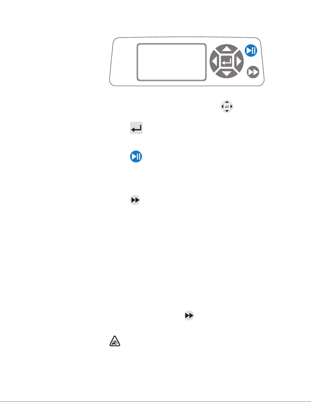
Figure 3-1. Control Panel
• To navigate all menus on the drive use the directional pad
directly to the right of the LCD screen.
• The (ENTER) key located in the middle of the directional pad
is used to enter or select a highlighted field or option. This key is often
referred to as the ENTER key in this manual.
• The (START/STOP) key located at the top right of the control
panel is used to start and pause the drive. This key is functional only
when in one of the four operating modes: Continuous, Time Dispense,
Copy Dispense, or Volume Dispense. This key is often referred to as
the START/STOP key in this manual.
• The (PRIME) key located at the bottom right of the control
panel is used to access the prime (fast forward) function. While
pressed, this key operates the drive at the maximum allowed speed/flow
rate and in the direction shown on the display. When released, the
drive returns to its original speed or flow rate.
1. Mount Pump Head to drive.
2. Insert appropriate tubing into Pump Head.
3. Insert tube inlet into supply fluid.
4. Insert supply outlet into desired container.
5. Turn on pump using switch located on the back of the drive.
6. Press and hold the PRIME key on the drive console to prime the
pump. Priming will stop when key is released.
CAUTION: Keep fingers away from rotor while pump is in
operation. Stop pump before loading or unloading tubing.
3-2 MASTERFLEX®L/S Digital Pump Drive Operating Manual Masterflex
Section 3
Operation
Priming the Pump
Control Panel
Page 17

CONTINUOUS MODE refer to Continuous Mode in this manual.
TIME DISPENSE MODE refer to Time Dispense Mode in this manual.
COPY DISPENSE MODE refer to Copy Dispense Mode section in this
manual.
VOLUME DISPENSE MODE refer to Volume Dispense Mode section in
this manual.
REMOTE CONTROL MODE refer to Remote Control Mode section in
this manual.
CUMULATIVE VOLUME: The drive stores and displays the cumulative
volume in units based on flow rate units (see SETUP MENU in this
section). The Cumulative Volume can also be reset to zero.
NOTE: The Cumulative Volume is dependent on the Tubing Size selected.
(See SETUP MENU in this section.)
SOUNDS: An audible “beep” can be enabled to indicate a keypad press,
the end of a dispense and/or the end of a batch.
AUTOSTART: By default the drive will not restart when power is applied.
To enable this feature select AUTOSTART and then ON. The drive will
now restart when power is reapplied.
DISPLAY CONTRAST: This display can be adjusted using the
UP/DOWN (▲/▼) arrows after selecting this menu item.
LANGUAGE: After selecting this menu, the user will be able to select one
of seven different languages.
NOTE: If the language is accidentally changed and the user would like to
reset it to the default language (English), press and hold the UP/DOWN
(▲/▼) keys when power is reapplied.
DEFAULT SETTINGS: Selecting this menu item and pressing the
ENTER key will restore default settings. To restore drive to default settings
the user may also press and hold the LEFT/RIGHT
(/)keys when
power is reapplied.
▲
▲
MASTERFLEX®L/S Digital Pump Drive Operating Manual 3-3Masterflex
Section 3
Operation
Main Menu
Page 18

3-4 MASTERFLEX®L/S Digital Pump Drive Operating Manual Masterflex
Section 3
Operation
Tubing Calibration
1. Mount Pump Head to drive.
2. Insert appropriate tubing into Pump Head.
3. Insert tube inlet into supply fluid.
4. Insert tube outlet into desired container. Container should be a
graduated container or a container placed on a scale may be used for
increased accuracy.
If using a scale, an acceptable weight to volume conversion for water
is 1 gram = 1 mL.
5. Turn on drive using power switch located on the rear of the drive.
6. Go to the Main Menu or Mode Setup Menu by selecting the SETUP
icon and pressing the ENTER key. Use the UP and DOWN keys
to highlight TUBING CAL in the Main or Setup Menu and press the
ENTER key.
7. Set the drive for the desired flow direction, tube size, and flow rate.
Note that these settings are retained and transferred to other mode
screens when entering or leaving the TUBING CAL screen.
• The flow direction is set using the directional keypad to highlight
the directional arrow. Pressing ENTER will toggle arrow between
CW and CCW.
• The tube size is set using the directional keypad to highlight the
tube size field. Press ENTER and use the UP/DOWN keys to
select the tube size. Press ENTER to SAVE the selection and
return to TUBING CAL screen.
• The estimated flow rate is set using the directional keypad to
highlight the flow rate field. Press ENTER and use the
LEFT/RIGHT keys to select the digit to be changed. Use the
UP/DOWN keys to adjust the flow rate value. Press ENTER to
SAVE the setting and EXIT field using arrow keys. The drive will
adjust this flow rate after calibration is complete.
• Note that the calibration volume is fixed and cannot be changed.
8. Press and hold the prime key on the drive console to prime the
pump. Priming will stop when key is released.
9. Place a measuring container at the pump outlet. Highlight the START
field and press the ENTER key. The drive will run based on the
default volume at the estimated flow rate selected.
Page 19

MASTERFLEX®L/S Digital Pump Drive Operating Manual 3-5Masterflex
Section 3
Operation
10. Upon completion of the calibration run period, the CAL VOLUME
field will be highlighted. Press the ENTER key and adjust the CAL
VOLUME to the measured quantity. Use the LEFT/RIGHT keys to
select digit to be changed, use the UP/DOWN keys to adjust the
value, and press ENTER to SAVE setting and EXIT the field.
A lower case “c” should now be displayed when the calibrated tubing
size is selected. The volume units will depend on the flow rate units.
The flow rate unit mL/min will result in a volume unit of mL; oz/min
will result in a volume unit of oz.
Tubing Calibration Notes
• If the drive is stopped during calibration, empty the container and
re-start the procedure.
• Calibration time at maximum allowable flow rate (default max
flow rate) is 5-10 seconds and at minimum allowable flow rate
(approximately 4% of the maximum flow rate) is 4 minutes.
Select the CUSTOM tube size for other tubing sizes or lower
flow rates.
• Minimum and maximum flow rates will change after a tubing
calibration due to a re-calculation of the vol/rev.
• Optimum results are best obtained after tubing has been broken in
by running in pump for at least 10 minutes. Steps 8-10 can be
repeated as necessary to optimize the accuracy of the tubing cal.
CAL RUN TIME FORMULA
60 / (flow rate [mL/min] / cal volume [mL]) = cal run time (seconds)
INVALID CAL RUN TIME EXAMPLE
• tube size 13 flow rate range is 0.006 mL/min – 36.0 mL/min
• at flow rate of 1 mL/min, cal run time calculation is as follows:
60 / (1 mL/min / 6 mL) = 360 seconds
360 seconds exceed the max run time of 4 minutes (240 seconds)
Tubing Calibration
(continued)
Page 20

3-6 MASTERFLEX®L/S Digital Pump Drive Operating Manual Masterflex
Section 3
Operation
All four operation mode screens contain a SETUP icon in the upper
right hand that gives quick access to the SETUP menu. The exact options
that can be accessed through the SETUP menu will depend on the
operating mode currently in use:
1. Selecting the SETUP Menu: In any of the four operating modes, use
the directional pad and enter key to select the SETUP icon from the
mode operation screen.
2. Navigating the SETUP Menu: Use the directional pad and the
ENTER key to select desired setting.
A breakdown of the setting features common to all modes follows. Other
settings are related to the specific operating mode currently in use and can
be accessed through the mode operation screen as well.
Flow Unit: Select desired flow unit to be displayed.
Tubing Size: Size and Maximum Flow Rate are displayed. Select desired
tubing size.
Flow Rate: Set the flow rate in flow unit listed at the top of the screen.
(NOTE: To change flow unit, see Flow Unit above.) When the entire rate
field is highlighted, press ENTER. The digits can be navigated individually
using the UP/DOWN arrows; switch between digits using the
LEFT/RIGHT arrows. After selecting an optimal flow rate, press ENTER
again to validate.
Tubing Calibration: See Tubing Calibration.
Pump Direction: Select the direction of the pump flow.
Sounds: Select a beep for keypad, end of dispenses, and batches.
Remote Control: See Remote Control.
Keypad Lockout: Allows for the keypad to be locked and unlocked.
Cumulative Volume: View and reset cumulative volume.
Main Menu: Return to the Main Menu.
Exit: Return to the Mode Operation screen.
Setup Menu
Page 21

MASTERFLEX®L/S Digital Pump Drive Operating Manual 3-7Masterflex
Section 3
Operation
Display Legend: Below is a screenshot of the screen display for the drive in
Continuous Mode. An explanation of the information on the screen follows.
Figure 3-2. Continuous Mode Screen
A. Mode Display: Current operating mode in which the drive will operate.
Pressing ENTER key when highlighted will cycle through the different
operation modes.
B. Setup : Pressing the ENTER key on this icon goes to the Setup
screen. The Setup screen contains most functions that can be accessed
from the Continuous Mode operation screen, including: flow units,
tubing size, flow rate, pump direction, remote control, and keypad
lockout. The Setup screen also provides access to tubing calibration,
sounds, cumulative volume and the Main Menu.
C. Flow Direction: Pressing the ENTER key on this icon toggles between
clockwise and counterclockwise flow direction.
D. Flow Units: Pressing the ENTER key on this icon goes to the Flow Unit
selection screen. NOTE: % and rpm are available in Continuous Mode only.
When switching to Copy Dispense or Volume Dispense Modes % and rpm
units will change to mL/min with values dependent on tubing size selected.
E. Tubing Size: Pressing the ENTER key on this icon goes to the tubing
size selection screen.
F. Current Flow Rate: The center digits show the flow rate of the drive in the
unit of measure selected and shown to the right (see position D, Figure 3-2).
G. Local/Remote or : Pressing the ENTER key on this icon goes to
the Remote Control setup screen. This icon indicates whether your
drive is in local or remote control mode. If the solid rectangle appears
in the center of the figure the drive is set to be operated locally. If the
solid rectangle does not appear in the center of the figure the drive is
set to be operated by remote control.
H. Key Pad Lock : Pressing the ENTER key on this icon goes to the
Keypad Lockout screen. Locking the keypad will prevent someone from
changing the settings on the drive. When locked this icon changes to .
Continuous Mode
Screen
CONTINUOUS MODE
100.00
17
mL/min
A
I
H
C
D
E
B
G
F
or
Page 22

3-8 MASTERFLEX®L/S Digital Pump Drive Operating Manual Masterflex
Section 3
Operation
Figure 3-3. Continuous Mode Operation
1. Getting Started: From the Main Menu, use the ENTER key to
select Continuous Mode to enter the Continuous Mode Operation
screen.
2. Calibrating Tubing: Before operating the pump, insert desired tubing into
the Pump Head. For more information, see “Tubing Calibration”.
3. Preparing External Supplies: Insert tube inlet into supply fluid. Next,
insert tube outlet into desired container.
4. Starting the Drive: From this operation screen, simply pressing the
START/STOP key will start the drive at the speed/flow rate and
direction shown. In Continuous Mode the drive will operate at the
displayed speed/flow rate and direction continuously.
5. Stopping the Drive: To pause or stop the drive, press the
START/STOP key in the top right hand corner of the console.
6. Changing Speed/Flow Rate: To change the speed/flow rate of the drive,
use the directional pad to highlight the numeric field in the center of the
display and press the ENTER key. This puts you in a position to change
the speed/flow rate of the drive at the farthest digit to the right (tenths,
hundredths, thousandths, etc depending on flow unit). Pressing the UP
arrow on the directional pad will increase the speed/flow rate by one
value and pressing the DOWN arrow will decrease the speed/flow rate by
one value. Pressing the ENTER key again will show all the possible digits
that can be manipulated for the specific flow unit currently in use; use the
LEFT/RIGHT arrows on the directional pad to move between digits and
the UP/DOWN arrows to increase or decrease the value, respectively.
Once desired speed/flow rate is selected, press ENTER key a final time to
set the drive to operate at that speed/flow rate.
7. Changing Flow Unit: To change the flow unit of the drive pause the
drive using the START/STOP key. Next, use the directional pad to
select the Flow Units icon and press the ENTER key. Use the
UP/DOWN arrow on the directional pad to select the desired flow
unit and press the ENTER key to choose that unit. The drive will now
operate in that flow unit. Press the START/STOP key to resume
operating the drive.
Continuous Mode
Operation
CONTINUOUS MODE
100.00
17
mL/min
Page 23

MASTERFLEX®L/S Digital Pump Drive Operating Manual 3-9Masterflex
Section 3
Operation
Display Legend: Below is a screenshot of the screen display for the drive in
Time Dispense Mode. An explanation of the information on the screen follows.
Figure 3-4. Time Dispense Mode Screen
A. Mode Display: Current operating mode.
B. Setup : The Setup screen can be used to select flow units, tubing size,
flow rate, tubing calibration, sounds, cumulative volume, and Main
Menu. The Setup screen contains some functions that can be accessed
from the Time Dispense Mode operation screen, including: pump
direction, on/off time, batch count, remote control, and keypad lockout.
C. Flow Direction: Pressing the ENTER key on this icon toggles between
clockwise and counterclockwise flow direction.
D. Pump ON Time: When this field is highlighted the drive is ON.
NOTE: The drive will not show 00:00 when switching from ON to
OFF Time.
E. Pump OFF Time: When this field is highlighted the drive is OFF.
F. Batch Count: Displays the number of cycles dispensed in the batch.
G. Local/Remote or : Pressing the ENTER key on this icon goes to
the Remote Control setup screen. This icon indicates whether your
drive is in Local or Remote Control mode. If the solid rectangle
appears in the center of the figure the drive is set to be operated locally.
If the solid rectangle does not appear in the center of the figure the
drive is set to be operated by remote control.
H. Key Pad Lock : Pressing the ENTER key on this icon goes to the
Keypad Lockout screen. Locking the keypad will prevent someone
from changing the settings on the drive. When locked this icon
changes to .
I. Time Display: The center digits show the remaining time of the drive
in the ON or OFF Time highlighted on the right of the display
(position D or E, Figure 3-4).
Time Dispense Mode
Screen
TIME DISP. MODE
00:00:00
OFF
ON
1000/2000
A
I
H
C
D
E
B
F
G
or
Page 24

3-10 MASTERFLEX®L/S Digital Pump Drive Operating Manual Masterflex
Section 3
Operation
Figure 3-5. Time Dispense Mode Operation
1. Getting Started: From the Main Menu, use the enter key to select Time
Dispense Mode to enter the Time Dispense Mode Operation screen.
2. Calibrating Tubing: Before operating the pump, insert desired tubing
into the Pump Head. For more information, see “Tubing Calibration”.
3. Choosing Settings: Select desired flow unit, tube size, flow rate, pump
direction, etc. For more information see “SETUP Menu.”
4. Preparing Tubing: Insert tube inlet into supply fluid. Next, insert tube
outlet into desired container.
5. Selecting Flow Rate: Use the directional pad and ENTER key to select
the Setup icon. Use the UP/DOWN arrows on the directional pad to
select Flow Rate. In the Flow Rate selection screen, press the ENTER
key and then use the UP/DOWN arrows on the directional pad to
select a desired flow rate. For faster entry, use the LEFT/RIGHT
arrows on the directional pad to move between digits and the
UP/DOWN arrows to increase or decrease the value, respectively.
Press ENTER one more time to validate the selected flow rate. Use the
directional pad to select EXIT to return to the Time Dispense Mode
Setup Screen.
6. Setting ON Time: To set the ON Time, use the directional pad and
ENTER key to select the ON field (see position D, Figure 3-4). Doing
so will highlight the timer in the center of the screen (see position I,
Figure 3-4). Pressing ENTER again, allows the timer to be set using
the UP/DOWN arrows. Switch between digits using the
LEFT/RIGHT arrows. Having selected an optimal ON Time, press
ENTER again to validate. The drive will now run for the time
appearing in the center of the screen.
Time Dispense
Mode Operation
TIME DISP. MODE
00:00:00
OFF
ON
1000/2000
Page 25

MASTERFLEX®L/S Digital Pump Drive Operating Manual 3-11Masterflex
Section 3
Operation
7. Setting OFF Time: To set the OFF Time, use the directional pad and
ENTER key to select the OFF field (see position E, Figure 3-4). Doing
so will highlight the timer in the center of the screen (see position I,
Figure 3-4). Pressing ENTER again, allows the timer to be set using
the UP/DOWN arrows. Switch between digits using the
LEFT/RIGHT arrows. Having selected an optimal OFF Time, press
ENTER again to validate. The drive will stop running for the time
appearing in the center of the screen. NOTE: If the OFF Time is set to
00:00:00, the drive requires a START/STOP input from the keypad or
the remote I/O Connector to start the next dispense.
8. Selecting Batch Size: Before running the drive at the selected ON/
OFF Times, select a batch size for the operation. To do so, use the
directional pad and the ENTER key to select the BATCH icon (see
position F, Figure 3-4). In the Batch Count screen, press the ENTER
key and then use the UP/DOWN arrows on the directional pad to
select a batch size. Switch between digits using the LEFT/RIGHT
arrows. Press ENTER one more time to validate the selected batch size.
When set to zero (0) the drive will run for an infinite number of cycles
and the symbol is displayed. Use the directional pad to select EXIT
to return to the Time Dispense Operation Screen.
9. Starting the Drive: The drive is now set to operate, press the
START/STOP key in the upper right hand corner to start the drive.
The drive can be paused at any time throughout the batch to adjust
flow direction, tubing size, flow units, flow rate, etc.
10. Resetting Batch: To reset a batch, use the directional pad and the
ENTER key to select the BATCH icon (see position F, Figure 3-4). In
the Batch Count screen, use directional pad to select RESET and press
the ENTER key to reset the batch count, select EXIT to return to the
main Time Dispense Mode operation screen.
Time Dispense Mode
Operation (continued)
Page 26

3-12 MASTERFLEX®L/S Digital Pump Drive Operating Manual Masterflex
Section 3
Operation
Copy Dispense Mode
Screen
Display Legend: Below is a screenshot of the screen display for the drive in
Copy Dispense Mode. An explanation of the information on the screen
follows.
Figure 3-6. Copy Dispense Mode Screen
A. Mode Display: Current operating mode.
B. Setup : The Setup screen can be used to select flow units, tubing
size, flow rate, tubing calibration, sounds, cumulative volume, and
Main Menu. The Setup screen contains some functions that can be
accessed from the Time Dispense Mode operation screen, including:
pump direction, on/off time, batch count, remote control, and keypad
lockout.
C. Flow Direction: Pressing the ENTER key on this icon toggles between
clockwise and counterclockwise flow direction.
D. Copy Amount Screen: See Copy Setting Screen, Figure 3-8.
E. Pump OFF Time: Highlighted when the drive is OFF.
F. Batch Count: Displays the number of cycles dispensed in the batch.
G. Local/Remote or : Pressing the ENTER key on this icon goes to
the Remote Control setup screen. This icon indicates whether your
drive is in local or remote control mode. If the solid rectangle appears
in the center of the figure the drive is set to be operated locally. If the
solid rectangle does not appear in the center of the figure the drive is
set to be operated by remote control.
H. Keypad Lock : Pressing the ENTER key on this icon goes to the
Keypad Lockout screen. Locking the keypad will prevent someone
from changing the settings on the drive. When locked this icon
changes to .
I. Percentage Completed: This icon displays the portion of fluid
dispensed as a percentage.
J. Copy Volume: Displays the Copy Volume while dispensing or the
OFF Time.
K.
Anti-Drip: A waterdrop icon present indicates that the Anti-Drip function
is on. For further information see Anti-Drip Function page 3-27.
COPY DISP. MODE
100.00
OFF
COPY
1000/2000
53 %
A
J
I
H
C
D
E
B
F
K
G
or
Page 27

MASTERFLEX®L/S Digital Pump Drive Operating Manual 3-13Masterflex
Section 3
Operation
Section 3
Operation
Copy Dispense Mode
Operation
Figure 3-7. Copy Dispense Mode Operation
1. Getting Started: From the Main Menu, use the ENTER key to select
Copy Dispense Mode to enter the Copy Dispense Mode operation
screen.
2. Calibrating Tubing: Before operating the pump, insert desired tubing
into the Pump Head. For more information, see “Tubing Calibration”.
3. Choosing Settings: Select desired flow unit, tube size, flow rate, pump
direction, etc. For more information see “Using the SETUP Menu.”
4. Preparing Tubing: Insert tube inlet into supply fluid. Next, insert tube
outlet into desired container.
5. Setting Copy Amount: See Copy Setting Operation.
6. Setting OFF Time: Use the directional pad and ENTER key to select
OFF on the display to enter the Pump OFF Time. Use the directional
pad and ENTER key to set the Pump OFF Time. The timer in the
center of the screen will be highlighted, and using the UP/DOWN
arrows will increase/decrease the farthest right digit of the time
interval. Switch between digits using the LEFT/RIGHT arrows. After
selecting an optimal OFF Time, press ENTER again to validate. The
drive will now rest for the time appearing in the center of the screen.
NOTE: If the OFF Time is set to 00:00:00, the drive requires a
START/STOP input from the keypad or the remote I/O Connector
to start the next dispense.
7. Setting Batch Size: Use the directional pad and ENTER key to select
the Batch Count icon from the operation screen (see position F,
Figure 3-6). From Batch Count screen use the UP/DOWN arrows to
select batch size. Press ENTER to validate batch size. When set to zero
(0) the drive will run for an infinite number of cycles and the
symbol is displayed. Select EXIT to return to the Copy Dispense
Mode screen.
• Batch count may be reset from BATCH COUNT screen by
selecting RESET.
COPY DISP. MODE
100.00
OFF
COPY
1000/2000
53 %
Page 28

3-14 MASTERFLEX®L/S Digital Pump Drive Operating Manual Masterflex
Section 3
Operation
8. Operating Drive: Press the START/STOP key to operate the drive at
the settings selected and displayed on the screen. Press again to pause
or stop the drive. Drive will automatically stop once batch is complete.
9. Reset Batch Count: Use the directional pad and the ENTER key to
select the BATCH COUNT icon (see position F, Figure 3-6). In the
BATCH COUNT screen, select RESET and press the ENTER key to
reset the batch count. Select EXIT to return to the Copy Mode
Operation screen.
10. Maximum Dispense Time: The specification for the maximum
dispense in Copy Mode is over 80+ hours at 600 rpm. Actual
maximum volume is dependant on tubing size and flow units selected.
Copy Dispense Mode
Operation (continued)
Page 29

MASTERFLEX®L/S Digital Pump Drive Operating Manual 3-15Masterflex
Section 3
Operation
Display Legend: Below is a screenshot of the screen display for the drive in
Copy Setting Mode. An explanation of the information on the screen follows.
Figure 3-8. COPY Setting Screen
A. Mode Display: Current operating mode.
B. START: This icon will start drive allowing for copy volume to be set.
C. Flow Direction: Pressing the ENTER key on this icon toggles between
clockwise and counterclockwise flow direction.
D. Volume Unit: This is dependent on the flow rate selected.
E. STOP: This stops the Copy and sets the volume to be dispensed. It is
displayed in position H.
F. CLEAR: Selecting this will clear the number displayed on the screen
and will allow for a new copy volume to be selected.
G. EXIT: Return to Copy Dispense Mode.
H. Volume: This is the amount that was dispensed during the copy.
COPY Setting Screen
mL/min
COPY
STOPEXIT
START
mL
10000
A
H
C
D
E
B
GF
CLEAR
Page 30

3-16 MASTERFLEX®L/S Digital Pump Drive Operating Manual Masterflex
Section 3
Operation
Figure 3-9. COPY Setting Operation
1. Getting Started: From the COPY DISPENSE MODE Screen select
COPY and ENTER.
2. Clear Volume: Using the directional Keypad select CLEAR and ENTER.
3. Establish Copy Volume: 3 methods are available to the user.
a. Place the desired container at the tubing outlet. Press the
START/STOP key to initiate the dispensing of fluid. When you have
reached the desired volume press the START/STOP key again. Select
EXIT and press ENTER. The drive will store the value of the copy in
memory and use that value in the COPY DISPENSE MODE.
b. Place the desired container at the tubing outlet. Select the START field
on the screen and press the ENTER key to initiate the dispensing of
fluid. The drive will now highlight the STOP field on the screen. When
you have reached the desired volume press the ENTER key to stop.
Select EXIT and press ENTER. The drive will store the value of the
copy in memory and use that value in the COPY DISPENSE MODE.
c. Place the desired container at the tubing outlet. Close the contacts
on the START/STOP input to initiate the dispensing of fluid.
When you have reached the desired volume, close and release the
contacts on the START/STOP input. Select EXIT and press
ENTER. The drive will store the value of the copy in memory and
use that value in the COPY DISPENSE MODE.
NOTE: The value displayed as the volume in the COPY SETTING screen
and the COPY DISPENSE Mode screen depend on the flow units selected.
RPM, and % are invalid. If these units have been selected the drive will
display a volume in mL, in the COPY DISPENSE MODE, that is
dependent on the tubing size selected.
See TUBING CALIBRATION to improve the accuracy of this conversion.
COPY Setting
Operation
mL/min
COPY
STOPEXIT
START
mL
10000
CLEAR
Page 31

MASTERFLEX®L/S Digital Pump Drive Operating Manual 3-17Masterflex
Section 3
Operation
Display Legend: Below is a screenshot of the screen display for the drive
in Volume Dispense Mode. An explanation of the information on the
screen follows.
Figure 3-10. Volume Dispense Mode Screen
A. Mode Display: Current operating mode.
B. Setup : The Setup screen can be used to select flow units, tubing size,
flow rate, tubing calibration, sounds, cumulative volume, and Main
Menu. The Setup screen contains some functions that can be accessed
from the Time Dispense Mode operation screen, including: pump
direction, on/off time, batch count, remote control, and keypad lockout.
C. Flow Direction: Pressing the ENTER key on this icon toggles between
clockwise and counterclockwise flow direction.
D. Flow Units: Select desired flow unit.
E. Pump OFF Time: Highlighted when the drive is OFF.
F. Batch Count: Displays the number of cycles dispensed in the batch.
G. Local/Remote or : Pressing the ENTER key on this icon goes to
the Remote Control setup screen. This icon tells you whether your
drive is in local or remote control mode. If the solid rectangle appears
in the center of the figure the drive is set to be operated locally. If the
solid rectangle does not appear in the center of the figure the drive is
set to be operated by remote control.
H. Keypad Lock : Pressing the ENTER key on this icon goes to the
Keypad Lockout screen. Locking the keypad will prevent someone from
changing the settings on the drive. When locked this icon changes to .
I. Volume: Displays the Volume while dispensing or the OFF Time.
J. Anti-Drip: A waterdrop icon present indicates that the Anti-Drip function
is on. For further information see Anti-Drip Function page 3-27.
Volume Dispense
Mode Screen
VOL DISP. MODE
100.00
OFF
mL
1000/2000
A
I
H
C
D
E
B
F
G
or
J
Page 32

3-18 MASTERFLEX®L/S Digital Pump Drive Operating Manual Masterflex
Section 3
Operation
Figure 3-11. Volume Dispense Mode Operation
1.
Getting Started: From the Main Menu, use the ENTER key to select Volume
Dispense Mode to enter the Volume Dispense Mode operation screen.
2. Calibrating Tubing: Before operating the pump, insert desired tubing
into the Pump Head. For more information, see “Tubing Calibration”.
3. Choosing Settings: Select desired flow unit, tube size, flow rate, pump
direction, etc. For more information see “SETUP Menu.”
4. Preparing Tubing: Insert tube inlet into supply fluid. Next, insert tube
outlet into desired container.
5. Setting Desired Volume: Using the directional pad highlight the numeric
field in the center of the display and press the ENTER key. This puts you
in a position to change the fluid volume of the drive at the farthest digit to
the right (tenths, hundredths, thousandths, etc., depending on your volume
unit). Pressing the UP arrow on the directional pad will increase the volume
by one value and pressing the DOWN arrow will decrease the volume by
one value. Pressing the ENTER key again will show all the possible digits
that can be manipulated for the specific volume unit currently in use; use
the LEFT/RIGHT arrows on the directional pad to move between digits
and the UP/DOWN arrows to increase or decrease the value, respectively.
Once desired volume is selected, press ENTER a final time to set the drive
to operate at that volume. Press the START/STOP key to resume operating
the drive.
6. Setting Pump OFF Time: Use the directional pad and ENTER key to
select OFF on the display (see position E, Figure 3-10) to enter the OFF
TIME. Use the directional pad and ENTER key to set the pump rest time.
The timer in the center of the screen will be highlighted, and using the
UP/DOWN arrows will increase/decrease the farthest right digit of the time
interval. If ENTER is pressed a second time while the timer is highlighted,
the digits can be navigated individually using the UP/DOWN arrows;
switch between digits using the LEFT/RIGHT arrows. After selecting an
optimal OFF time, press ENTER again to validate. The drive will now rest
for the time appearing in the center of the screen. NOTE: If the OFF Time
is set to 00:00:00, the drive requires a START/STOP input from the
keypad or the remote I/O Connector to start the next dispense.
Volume Dispense
Mode Operation
VOL DISP. MODE
100.00
OFF
mL
1000/2000
Page 33

MASTERFLEX®L/S Digital Pump Drive Operating Manual 3-19Masterflex
Section 3
Operation
7. Setting Batch Size: Use the directional pad and ENTER key to select
the Batch Count icon from the operation screen (see position F,
Figure 3-10). From Batch Count screen use the UP/DOWN arrows to
select batch size. Press ENTER to validate batch size. When set to zero
(0) the drive will run for an infinite number of cycles and the ∞
symbol is displayed. Select EXIT to return to drive operation screen.
• Batch count may be reset from the Batch Count screen by selecting
RESET.
8. Operating the Drive: Press the START/STOP key to operate the drive
continuously at the settings selected and displayed on the screen. Press
again to pause or stop the drive. Drive will automatically stop once
batch is complete.
9. Reset Batch Count: Use the directional pad and the ENTER key to
select the BATCH COUNT icon (see position F, Figure 3-10). In the
BATCH COUNT screen, select RESET and press the ENTER key to
reset the batch count. Select EXIT to return to the COPY MODE
OPERATION screen.
10. Maximum Dispense Time: The specification for the maximum
dispense volume in Volume Mode is over 80+ hours at 600 rpm.
Actual maximum volume is dependant on tubing size and flow units
selected.
Volume Dispense
Mode Operation
(continued)
Page 34

3-20 MASTERFLEX®L/S Digital Pump Drive Operating Manual Masterflex
Section 3
Operation
Figure 3-12. Remote Control Menu Screen
NAVIGATION: From the Main Menu or SETUP Menu select REMOTE
CONTROL and ENTER.
LOCAL: When this is selected the drive is controlled by the front panel
keypad, Start/Stop Input, Directional Input or Prime Input.
CURRENT INPUT: When this is selected, the drive is in remote control.
This allows the user to input a current signal to control the flow. The user has
an option to adjust the minimum, maximum and middle set points for
current and flow. By default the minimum (MIN) current is set to 4.2 mA
and the flow is set to 0. The maximum (MAX) is set to 20 mA and the flow is
set to maximum. The middle (MID) is auto calculated for a current and flow
that is centered between the MIN and the MAX. The MID can be adjusted if
other profiles are needed. The scaling can be inverted if necessary. To confirm
CURRENT INPUT MODE is selected, select EXIT after returning to the
Remote Control Menu, then select CONTINUOUS PUMP MODE. To
deselect Remote Current Input Mode select LOCAL and ENTER.
NOTE: When Current Input is selected the drive will not start until the
REMOTE CONTROL MODE is exited and CONTINUOUS PUMP
MODE is selected.
CURRENT OUTPUT: This allows the user to adjust the current output for a
given flow. The user has an option to adjust the minimum, maximum and
middle setpoints for current and flow. By default the minimum (MIN) flow is set
to 0.00 and the current is set to 4.0 mA. The maximum (MAX) is set to
maximum flow and the current is set to 20.0 mA. The middle (MID) is auto
calculated for a current and flow that is centered between the MIN and the MAX.
The MID can be adjusted if other profiles are needed. This allows for a threepoint calibration of the current output. The flow is linear between these points.
The scaling can be inverted if necessary. NOTE: Selecting Current Output will not
put user into REMOTE CONTROL MODE. Only selecting VOLTAGE
INPUT or CURRENT INPUT will put the user into Remote Control Mode, as
indicated by the empty house icon (see position G, Figure 3-2). NOTE: The
Current Output indicates the Running Command Speed. Use the Motor
Running contacts (normally open/closed) to indicate if pump is running.
Remote Control Menu
REMOTE CONTROL
LOCAL
CURRENT INPUT
CURRENT OUTPUT
VOLTAGE INPUT
VOLTAGE OUTPUT
START/STOP
EXIT
Page 35

MASTERFLEX®L/S Digital Pump Drive Operating Manual 3-21Masterflex
Section 3
Operation
Remote Control Menu
(continued)
VOLTAGE INPUT: When this is selected, the drive is in remote control.
This allows the user to input a voltage signal to control the flow. The user
has an option to adjust the minimum, maximum and middle setpoints
for voltage and flow. By default the minimum (MIN) voltage is set to
00.1 V DC and the flow is set to 00.0. The maximum (MAX) is set to
10.0 V DC and the flow is set to maximum. The middle (MID) is auto-
calculated for a voltage and flow that is centered between the MIN and
the MAX. The MID can be adjusted if other profiles are needed. The
scaling can be inverted, if necessary. To confirm VOLTAGE INPUT
MODE is selected, select EXIT after returning to the Remote Control Menu,
then select CONTINUOUS PUMP MODE. To deselect Remote Voltage
Input Mode select Local and ENTER.
NOTE: When Voltage Input is selected the drive will not start until the
REMOTE CONTROL MODE is exited and CONTINUOUS PUMP
MODE is selected.
VOLTAGE OUTPUT: This allows the user to adjust the voltage output for a
given flow. The user has an option to adjust the minimum, maximum and
middle set points for voltage and flow. By default the minimum (MIN) flow
is set to 00.00 and the voltage is set to 00.0V DC. The maximum (MAX) is
set to maximum flow and the voltage is set to 10.0V DC. The middle (MID)
is auto calculated for a voltage and flow that is centered between the MIN and
the MAX. The MID can be adjusted if other profiles are needed. This allows
for a three point calibration of the voltage output. The flow is linear between
these points. The scaling can be inverted if necessary. NOTE: Selecting Voltage
Output will not put the user into Remote Control Mode. Only selecting
Voltage Input or Current Input will put the user into Remote Control Mode,
as indicated by the empty house icon (see position G, Figure 3-2). NOTE: The
Voltage Output indicates the Running Command Speed. Use the Motor
Running contacts (normally open/closed) to indicate if pump is running.
START/STOP: The START/STOP input can be configured to be OFF
(factory default), or ON for the drive to run.
With the OFF selected (factory default), use of the START/STOP input is
optional. When the START/STOP input is open, the drive can still be started
using the START/STOP key, PRIME key, or PRIME input. In remote modes
the drive will also run if there is sufficient current or voltage at the input.
Closing the START/STOP input will cause the drive to run until the
START/STOP input opens or the START/STOP key is pressed. In Time
dispense, Copy dispense, and Volume dispense mode, only a momentary
START/STOP closure is needed to start the drive. If the drive is already
running in one of the dispense modes, a momentary START/STOP
closure will stop the drive. In SET COPY MODE, the START/STOP
input functions the same as in CONTINUOUS MODE; closing it will
cause the drive to run until it opens.
Page 36

3-22 MASTERFLEX®L/S Digital Pump Drive Operating Manual Masterflex
Section 3
Operation
Remote Control Menu
(continued)
The function of the START/STOP input is considerably simplified when
the ON is selected. The drive will not run under any condition unless the
START/STOP input is closed.
Table 3-1. Continuous Mode Operation
MENU SETTINGS START/STOP INTERNAL MODE mA or V MODE
SETUP OPTIONS INPUT
AUTO START/STOP Drive State When Drive Response When Drive Running
START REQUIRED Powered OFF Powered ON (sufficient level)
When Powered OFF
Drive Response when
Powered ON
(sufficient level present)
OFF OFF OPEN Running Not running Not running
OFF OFF OPEN Not running Not running Not running
OFF OFF CLOSED Forced run due Not running Not running
to S/S CLOSED
OFF ON OPEN Forced not running Not running Not running
due to S/S OPEN
OFF ON CLOSED Forced run due Not running Not running
to S/S CLOSED
ON OFF OPEN Running Running Running
ON OFF OPEN Not running Not running Running
ON OFF CLOSED Forced run due Running Running
to S/S CLOSED
ON ON OPEN Forced not running Not running Not running
due to S/S OPEN
ON ON CLOSED Forced run due Running Running
to S/S CLOSED
NOTE: In Continuous Mode when using the START/STOP input the drive is started with a closed contact and
stopped when the contacts are opened.
Table 3-2. Dispense Mode Operation
MENU SETTING SETUP OPTIONS START/STOP Drive State When Drive Response When
INPUT Powered OFF Powered ON
AUTO START START/STOP
REQUIRED
OFF OFF OPEN Running Not running
OFF OFF OPEN Not running Not running
OFF OFF CLOSED* Forced run due Not running
to S/S CLOSED
OFF ON OPEN Forced not running Not running
due to S/S OPEN
OFF ON CLOSED Forced run due Not running
to S/S CLOSED
ON OFF OPEN Running Running
ON OFF OPEN Not running Not running
ON OFF CLOSED* Forced run due Running
to S/S CLOSED
ON ON OPEN Forced not running Not running
due to S/S OPEN
ON ON CLOSED Forced run due Running
to S/S CLOSED
* NOTE: In Dispense Modes and START/STOP MENU SETUP Option OFF the drive will start a dispense
with a momentary contact closure and stop with a momentary contact closure during both the dispense
period and interval period.
Page 37

MASTERFLEX®L/S Digital Pump Drive Operating Manual 3-23Masterflex
Section 3
Operation
DB-25 Pin
Configuration with
Wiring Scheme
Contact Arrangements
CAUTION: Power must be turned off before connecting the
external remote control cable to prevent damage to the drive.
NOTE: Open collector outputs in "low impedance" state are at earth
ground and when in "high impedance" state are essentially floating. See
Open Collector page following.
Figure 3-13. DB-25 Pin Configuration with Wiring Scheme
A. START/STOP
B. CW/CCW
C. OUTPUT 0-20mA; 4-20mA
D. INPUT 0-20mA; 4-20mA
E. INPUT 0-10V
F. OUTPUT 0-10V
G. TACH OUTPUT
K
HA
G
B
JI C E
D
F
M
L
13 112 11 10 9 8 7 6 5 4 3 2
25 24 23 22 21 20 19 18 17 16 15 14
H. PRIME
I. MOTOR RUNNING N.O. C(1A @ 24 V)
J. MOTOR RUNNING N.C. (1A @ 24 V)
K. 24V (150mA max.)
L. General Alarm
M. Local.Remote Indicator
Pin No. Description
DB-25
1 Speed Control Voltage Input (0-10 V)
2 Speed Control Current Input (0-20 mA)
3 Speed Control Input Ground Return
4 Speed Signal Current Output (0-20 mA)
5 Speed Signal Output Ground Reference
6 (Motor Running N.O. Default) 1A @24 V (Open Collector)
7 Motor Running Ground Return
8 (Motor Running N.C. Default) 1A @24 V (Open Collector)
14 Speed Signal Voltage Output (0-10 V)
15 Remote Start/Stop Input
16 Remote CW/CCW Input
17 Remote Start/Stop, CW/CCW, Prime Grnd Ref.
18 Tach Ground Reference
19 Tach Output (open collector)
20 Remote Prime Input
9 Reserved – Not Used
10 Reserved – Not Used
11 Auxiliary Input (Computer Compatible Drive Only)
12 Auxiliary Input Return (Computer Compatible Drive Only)
21 Auxiliary Output #1 (Computer Compatible Drive Only)
22 Auxiliary Output #2 (Computer Compatible Drive Only)
23 General Alarm (Open Collector)
24 Local.Remote Indicator (Open Collector)
25 Aux 24V+ (150 mA)
13 Aux 24V- (150 mA)
NOTE: Pins 5, 13, 17, and 18 are at earth ground, all are suitable for use
with START/STOP, PRIME, Direction, Tach, LOCAL/REMOTE,
General Alarm Signals and Current and Voltage Outputs.
Page 38

3-24 MASTERFLEX®L/S Digital Pump Drive Operating Manual Masterflex
Section 3
Operation
31-Pin
Configuration with
Wiring Scheme
Contact Arrangements
Pin No. Description
1 Speed Control Voltage Input (0-10 V)
2 Speed Signal Voltage Output (0-10 V)
3 Speed Control Current Input (0-20 mA)
4 Remote Start/Stop Input
5 Speed Control Input Ground Return
6 Remote CW/CCW Input
7 Speed Signal Current Output (0-20 mA)
8 Remote Start/Stop, CW/CCW, Prime Grnd Ref.
9 Speed Signal Output Ground Reference
10 Tach Ground Reference
11 (Motor Running N.O. Default) 1A @24 V (Open Collector)
12 Tach Output (open collector)
13 Motor Running Ground Return
14 Remote Prime Input
15 (Motor Running N.C. Default) 1A @24 V (Open Collector)
16 Reserved – Not Used
17 Reserved – Not Used
18 Reserved – Not Used
19 Reserved – Not Used
20 General Alarm (Open Collector)
21 Reserved – Not Used
22 Local.Remote Indicator (Open Collector)
23 Reserved – Not Used
24 Aux 24V+ (150 mA)
25 Aux 24V- (150 mA)
26 Reserved – Not Used
27 Reserved – Not Used
28 Reserved – Not Used
29 Reserved – Not Used
30 Reserved – Not Used
31 Reserved – Not Used
25
19
31- #20
14
8
3
1
2
7
13
18
24
29
31
30
Figure 3-14. 31-Pin Configuration with Wiring Scheme
CAUTION: Power must be turned off before connecting the
external remote control cable to prevent damage to the drive.
NOTE: Open collector outputs in "low impedance" state are at earth
ground and when in "high impedance" state are essentially floating. See
Open Collector page following.
NOTE: Pins 8, 9, 10, and 25 are at earth ground, all are suitable for use
with START/STOP, PRIME, Direction, Tach, LOCAL/REMOTE,
General Alarm Signals and Current and Voltage Outputs.
Page 39

INPUTS
Remote CW/CCW, Remote Start/Stop, Remote Prime, & Aux. In:
The remote control inputs work with current sinking outputs (opencollector NPN transistor outputs without passive pull-up resistors) or
contact closures to DC common (earth ground). A continuous active low
to the Remote Start/Stop input causes the drive to run, while a continuous
active low to the Remote CW/CCW input causes the drive to run CCW.
The motor is brought to a controlled stop before reversing direction. A
continuous active low to the Remote Prime input causes the drive to run
at full rated speed.
CURRENT CLOSED INPUT 1 mA TYP
VOLTAGE OPEN INPUT 3.2 V TYP
THRESHOLD CURRENT TO ACTIVATE 0.5 mA TYP
Remote Analog Input:
4-20 mA Input: 250 ohms typical input impedance ref. to signal
ground. 4 mA, Stop; 20 mA, Full Speed (Default
Settings) 10 Bit Resolution
Overload Capability: 10 V or 40 mA max.
0-10 V Input: 10 K ohms typical input impedance ref. to signal
ground. 0 V, Stop; 10 V, Full Speed (Default
Settings) 10 Bit Resolution
OUTPUTS
4-20 mA Output: 0 to 600 ohms max. load referenced to earth ground.
4 mA, Stop; 20 mA, Full Speed (Default
Settings) 10 Bit Resolution
0-10 V Output: 1.0 K ohms min. load referenced to earth
ground. 0 V, Stop; 10 V, Full Speed (Default
Settings) 10 Bit Resolution
Tach Output: Open Collector, 1.0A @ 28V DC
Frequency range: 100 to 6000 Hz or 100 to 1000 Hz, 50% Duty
Cycle. (10 Hz = 1 pump rpm)
Logic Outputs: Open Collector, 1.0 A @ 28V DC
Motor Running Outputs: Normally Open and Normally Closed when drive is
running.
General Alarm Output: Open (High Impedance) when an alarm is displayed.
Local/Remote Indicator: Open (High Impedance) when in remote
control mode (Voltage Input, Current Input, or
RS232).
MASTERFLEX®L/S Digital Pump Drive Operating Manual 3-25Masterflex
Section 3
Operation
Remote Control Inputs
and Outputs
Table 3-3. Remote Control Inputs and Outputs
Page 40

3-26 MASTERFLEX®L/S Digital Pump Drive Operating Manual Masterflex
Section 3
Operation
Some remote outputs on this drive (Tachometer, Local/Remote, Motor
Running and Alarm) are “open collector” type outputs and cannot be
wired in the same manner as relay outputs. An open collector output is
not isolated and must be configured differently than a relay output.When
the open collector output is active, the output is effectively switched to
earth ground and if improperly terminated could result in damage to the
drive and/or external equipment.
Recommendation
When connecting to open collector outputs, the output should be
connected to a current limiting resistor and then to a positive supply
source which is less than 28V DC. Typically this would be connected to a
24V PLC input (see Figure 3-15).
NOTE: when using the 24V supply on the interface connector, current
draw must be limited to 150 mA.
NOTE: DO NOT connect 120V supply lines to open collector outputs!
Figure 3-15. Terminating Open Collector Outputs to a PLC
Open Collector
Outputs
+24V
To PLC
Output
10k
Page 41

MASTERFLEX®L/S Digital Pump Drive Operating Manual 3-27Masterflex
Section 3
Operation
The same drive offers an Anti-Drip feature. The tendency of fluid to drip
after a dispense is dependant on several factors including tubing size,
tubing orientation, and the viscosity of the fluid. To minimize this drip the
drive will reverse direction after a dispense to draw the fluid back at the
end of the tubing.
To access this feature select in either Copy Dispense Mode or Volume
Dispense Mode ANTI-DRIP.
Figure 3-16. Anti-Drip Screen
If the ANTI-DRIP function is desired, select ON and a second screen will
appear which will allow the user to input how many degrees of reverse
rotation the drive will perform. Typical values range from 5 to 45 degrees.
To exit without changing the current setup select EXIT.
Figure 3-17. Anti-Drip Degrees Screen
With the number highlighted press the ENTER key and use the UP and
DOWN, and RIGHT and LEFT arrows to change the digits. Press the
ENTER key and then select EXIT to save the setting. The drive will now
reverse after every dispense.
Anti-Drip Function
ANTI-DRIP
ON
OFF
EXIT
ANTI-DRIP
EXIT
°
45
Page 42

3-28 MASTERFLEX®L/S Digital Pump Drive Operating Manual Masterflex
Section 3
Operation
The Linkable Instrument Network is a serial communication system
consisting of a control computer with one RS-232C port and one or more
satellite units. A satellite unit can be a pump drive, mixer controller, or any
future product that conforms to the communications protocol defined in
this description. This description describes all the information needed to
communicate with a pump drive. Since much of this information applies
to other products, the term “satellite unit” will be used as a generic term
for all devices compatible with the Linkable Instrument Network. The
term “pump drive” will be used when the information applies only to
MASTERFLEX Computerized Drives.
All communications between the control computer and satellite units is
based on a pseudo daisy-chain principle. The transmission line of the
control computer will pass through the input and output buffers in each of
the satellite units. Each satellite unit will have the ability to turn the
buffers on and off to block communications from other units below it in
the daisy-chain. The output of the control computer would pass through
each of the pump drives without software assistance from the pump drive.
All Pump Drives in the daisy-chain must be powered up to enable
communications with all drives.
The receive line of the control computer will originate in the transmitter of the
last satellite in the chain. It will also be double buffered through each satellite.
Each of the pump drives will have the ability to turn off its input receive line
and place its own transmitter on the receive line to the control computer.
A third line, the Request To Send (RTS) will be a similarly buffered line.
Each satellite will have the ability to set this line to signal the computer its
request to send.
The maximum number of satellites is limited to 25 by the Linkable
Instrument Network software to minimize communication time. However,
up to 89 satellites could be controlled by a single RS-232C port using custom
software since satellite units can be assigned any number from 01 to 89.
Some drives are equipped with a USB Mini Port. The drive supports USB 2.0
through the use of WINLIN software (sold separately). WINLIN can be
operated on Windows® XP and Windows® VISTA operating systems. USB needs
to be selected within WINLIN in order for the drive to be recognized by the
host computer. See the accessories section of this manual for cable information.
NOTE: USB is not recommended for long term continuous use due to
Windows® operating system issues. For long running applications use
RS232 communications.
Serial
Communication
Specification
Linkable Instrument
Network
Drives
USB
Page 43

MASTERFLEX®L/S Digital Pump Drive Operating Manual 3-29Masterflex
Section 3
Operation
The Digital PWM BLDC Drives communicate with each other and a PC via a
standard DB-9 modem cable (Cat. #22050-54). Older satellite units have a
dual 6-position modular phone jack labeled “IN” and “OUT”. Pin 1 on both
jacks is located towards the top of the drive. The control computer will have a
standard DB-25 plug as found on most RS-232C connections. The DB-9 “AT”
type connector can also be used with the DB-9 to DB-25 adapter included with
the 07550-64 Computer to Pump cable assembly.
DRIVE DB9 IN
Pin 2 - TXD Transmit signal to computer
Pin 3 - RXD Receive signal from computer
Pin 5 - GND Ground
Pin 8 - RTS Request to send to the computer
DRIVE DB9 OUT
Pin 2 - RXD Receive signal from next satellite
Pin 3 - TXD Transmit signal to next satellite
Pin 5 - GND Ground
Pin 8 - RTS From next satellite
DB-25 PLUG ON CONTROL COMPUTER
Pin 2 - Transmitted data to satellite
Pin 3 - Received data from satellite
Pin 5 - Clear to send—RTS from satellite
Pin 7 - Ground
DB-9 PLUG “AT” type ON CONTROL COMPUTER (DTE) AND SATELLITE
Pin 3 - Transmitted data to satellite
Pin 2 - Received data from satellite
Pin 8 - Clear to send—RTS from satellite
Pin 5 - Ground
DB-9 SOCKET ON SATELLITE (DCE)
Pin 3 - Receive signal from the computer
Pin 2 - Transmit signal to the computer
Pin 5 - Ground
Pin 8 - Request to send—(RTS) to the computer
The serial lines between units will be passed from unit-to-unit by a hardware
buffer on the input, connecting it directly to the output driver through a hardware
gate. This way any output only sees one input load. If power is turned off on any
pump drive, all drives below it in the daisy-chain cannot communicate.
Serial Connections
Figure 3-18. Serial Daisy-Chain Connections
Page 44

3-30 MASTERFLEX®L/S Digital Pump Drive Operating Manual Masterflex
Section 3
Operation
The serial data format is full duplex (simultaneously transmit and receive),
1 start bit, 7 data bits, one odd parity bit, and one stop bit at 4800 bits
per second. All data transmitted will consist of characters from the
standard ASCII character set.
NOTE: Odd parity is defined such that the sum of the eight individual bits
is an odd number (1, 3, 5 or 7).
All transmissions originate or are requested by the control computer (master).
It may issue commands directly and it may request that the satellites report.
When asked to report, the satellite would send the data requested. Should a
satellite require communication with the computer, it has the ability to
operate the request to send (RTS) line. Upon receiving the request, the
computer would respond via the serial line (see Serial Connections section).
Normal start-up would consist of turning on all the satellite units first and
then the control computer. Each satellite will enable its receive and transmit
buffers and activate its RTS line. The control computer would then send
the enquire <ENQ> command in response to the active RTS line. Upon
receiving the <ENQ> command, all satellites with an active RTS line
would disable its receive and transmit buffers to the satellites below it in
the daisy-chain. Next the pump drives would respond with one of the
following strings depending on its model number and version.
<STX>P?0<CR> = 600 rpm
<STX>P?2<CR> = 100 rpm
The control computer would only see the response from the first satellite
in the chain since communications with the others is now blocked. The
control computer would then send back <STX> Pnn<CR> with nn being a
number starting with 01 for the first satellite and incrementing for each
satellite up to 25 maximum. If the pump drive receives the data without
errors it will perform the following steps:
1. Deactivate its RTS line and enable the receive buffers to the next satellite.
2. Send an <ACK> to the control computer.
3. Enable the transmit buffer from the next satellite within
100 milliseconds after the last byte has been sent.
4. Put a “P” and the satellite number received in the first 3 positions on
the satellite display.
Serial Data Format
Serial Protocol
Start-Up Sequence
Page 45

MASTERFLEX®L/S Digital Pump Drive Operating Manual 3-31Masterflex
Section 3
Operation
After the control computer receives the <ACK> it will see the RTS from
the next satellite and again issue the <ENQ> command. The above process
will be repeated until all satellites are numbered.
If a satellite does not receive valid data from the control computer or
detects a transmission error, it will send a <NAK>. When the control
computer receives the <NAK> it will resend the <STX>Pnn<CR> to the
satellite. The Error Handling section describes the maximum retries the
control computer will perform.
If a satellite is turned on after all the other satellites have been numbered,
it will be numbered the same as described above with the next available
number if no commands have been sent to the other satellites. If
commands have been issued, the satellite is assigned a temporary number
starting with 89 and decrementing for each subsequent satellite. This will
cause the satellite to release its RTS so normal communication can
proceed. The operator will be alerted to the condition that another satellite
has come on-line and needs to be numbered. The operator will then be
able to assign the new satellites a number so that they will appear correctly
in the system. The control computer will use the following commands to
renumber a satellite:
<STX>PooUnn<CR>
The “oo” is the old satellite number and “nn” the new number.
If a satellite is requesting to be numbered and the control computer has
already issued 25 satellite numbers, the control computer will assign the
satellite the number 89 as described in the preceeding paragraph and alert
the operator to the situation.
If a satellite is powered down after it has been numbered, it will be treated
as a new unit as described above when it is powered up again.
Once a satellite is in the remote mode, it can be returned to local mode
using the control computer and the “L” command. If the control
computer program is no longer running, the satellite can be powered off
and then on to return it to local operation. If the “L” command is used,
the satellite will retain its assigned number and respond to request
commands from the control computer but ignore control commands.
Start-Up Sequence
(continued)
Remote/Local
Operation
Page 46

3-32 MASTERFLEX®L/S Digital Pump Drive Operating Manual Masterflex
Section 3
Operation
Most commands from the control computer are preceded with the start of text
<STX> character (02 hex), a satellite identification letter (P for Pump, M for
mixer) and a two digit satellite number (01 through 89). Numbers 00 and 90
through 99 are reserved for special cases. When the same command is to be
executed by all pump drives, 99 is sent for the satellite number. Following the
command character is the parameter field which varies in size from zero characters
to 32 depending on the command. A carriage return <CR>, (0D hex) is used to
indicate the end of a command string. (NOTE: the exceptions to this computer
issued command format are <ENQ>, <ACK> and <NAK>.) See Figure 3-18.
More than one command can be put in a command string as shown following:
<STX>P09S+0500.0V08255.37G <CR>
The above multiple command string example would set the speed at pump
satellite 09 to 500.0 rpm, clockwise direction, set 8255.37 revolutions and
start the drive. The maximum number of characters allowed in one pump
drive string is 38, including <STX>, Pnn and <CR>.
Command Features
1. INITIALIZING
Before a pump drive can be controlled, it must first be numbered. If any
command is issued before this is done, the satellite will not respond.
2. SETTING SPEED
If a SPEED command is issued after the speed has already been set, the
new speed will be used. If the pump drive is running and a different
direction is sent to the pump, the pump will send back a <NAK>. A
“H” command must first be issued before the direction can be
reversed.
3. SETTING REVOLUTIONS
When “Revolutions To Go” are set with the “V” command, they are
added to the total revolutions to go counter. The maximum this counter
can be is 99999.99. If a revolutions to go count is sent to the pump drive
which would cause the counter to overflow past 99999.99, the pump
drive will not add the value to its revolutions to go counter and will send
the control computer a <NAK>. The revolutions to go counter can be set
to zero by using the “Z” command, which will also cause the pump to
stop if it is running when the “Z” command is received.
Command Format
Figure 3-19. Command Format
Page 47

MASTERFLEX®L/S Digital Pump Drive Operating Manual 3-33Masterflex
Section 3
Operation
The parameter field sent by the control computer is variable in length. The
control computer will have the option of using leading zeroes, leading
spaces, or no padding at all.
For example, if 200 revolutions was to be sent with the “V” command, the
following list of parameters would all be accepted by the satellite as valid:
(s = space) 00200.00
ss200.00
sss200.00
sssss200
200.00
200.0
200
Satellite Data Fields
Any data that a satellite sends to the control computer will have a fixed
number of characters which is determined by the command. For example,
if the control computer requested the cumulative volume, it would always
receive 10 characters representing the cumulative volume (0000000.00 to
9999999.99).
When the control computer requests status from the pump drive (“I”
command or <ENQ>), the satellite will respond with the following status
information (see Figure 3-20):
Control Computer
Parameter Fields
Figure 3-20. Parameter Fields
Pump Drive
Status Request
Page 48

3-34 MASTERFLEX®L/S Digital Pump Drive Operating Manual Masterflex
Section 3
Operation
NOTE: “Pump not numbered” is also a pump status, but it is not included
in the pump status byte. This condition is handled separately using the P?x
(see Start Up Sequence section).
When the satellite sends the status information, any status conditions that
are latched by the satellite will be cleared by the control computer sending
an <ACK>Pnn<CR>. If the satellite receives the “I” command again, it will
respond with the same status information.
When the pump satellite correctly receives a command, it will send back
an <ACK> (06 hex) if it was not an all pumps command (P99). If data has
to be sent back to the control copy in response to the command, it will be
sent as shown in Table 3-2. If the satellite detected an error while receiving
a command, it will respond with a <NAK>.
Depending on the error code received from the satellite, the control
computer would have to take appropriate action to try to eliminate the
error condition. Communication errors of type 1, 2 or 3 indicate a
hardware type error: noisy communication lines, bad connection, glitches
or circuit failure. Communication error codes 4 or 5 could be hardware
errors as previously described or software errors caused by incorrect
commands or data being sent by the control computer. For hardware type
errors the control computer would try sending the same command to see if
the problem was only momentary. If an error code is returned four times
in a row or if there is no response at all, the control computer would abort
trying to send the command and notify the operator of the type of error.
If a satellite does not respond at all, the control computer can assume one
of the following:
1. If all other satellites connected after the satellite in question also don’t
respond, the communication link is broken at that point or the satellite
is defective.
2. If all other satellites respond, the unresponding satellite is either turned
off, removed from the loop, or defective.
Pump Drive Status
Request (continued)
Satellite Response
Error Handling
Page 49

MASTERFLEX®L/S Digital Pump Drive Operating Manual 3-35Masterflex
Section 3
Operation
When a satellite wants to communicate with the control computer, it will
turn on its request to send (RTS) line and then wait for the (ENQ) enquire
character (05 hex) from the control computer. The following list shows the
possible conditions that would cause the pump drive to activate its RTS line.
1. Auxiliary input status change.
2. Motor error.
3. Stop key pressed at satellite while in the remote mode.
4. Programmed volume was reached.
5. Power up.
The following is the sequence of events for when RTS is activated by a
pump drive:
1. Satellite enables RTS line.
2. When control computer detects RTS, it will transmit the (ENQ)
enquire command (05 hex) after it completes any communications it
may be in the process of preforming.
3. When the satellite that has its RTS line enabled receives the <ENQ> it
will disable its RS-232C buffers to block the other satellites below it in
the daisy-chain from communicating with the control computer. This
would give the satellite closest to the control computer the highest
priority if more than one satellite enabled its RTS line at the same time.
4. Next the pump drive will send the response from the “I” command as
shown in Pump Drive Status Request field.
5. If the control computer received the satellite response without any
errors (parity, overrun etc.) it will send an acknowledge
<ACK>Pnn<CR> which will cause the satellite to release its RTS line
and enable the RS-232C buffers allowing the satellites below it in the
daisy-chain to communicate. If the control computer detected any
error during the transmission it would send the enquire (ENQ) again
which would cause the satellite to re-send its response. The control
computer will retry a maximum of four times before aborting and
reporting the error to the operator.
6. If more than one satellite has its RTS line enabled, the control
computer would see only the response from the satellite closest to it.
After the closest satellite sent its response and released the RTS line,
the control computer would see the RTS of the other satellite and
again issue the enquire command which would allow the next satellite
with RTS active to respond.
Satellite Request to
Send
Page 50

3-36 MASTERFLEX®L/S Digital Pump Drive Operating Manual Masterflex
Section 3
Operation
7. If a satellite was responding to an enquire command and another
satellite with higher priority also started to respond, cutting off the first
responding satellite, the control computer would receive invalid data
and get some type of error (parity or framing). This would cause the
control computer to resend the enquire, but this time only the higher
priority satellite would respond since the communications with the
lower satellites is blocked.
Satellite Request to
Send (continued)
Command Characters from Parameter Field
Control Computer to Pump
A Request auxiliary input status none
B Control auxiliary outputs when G command executed xy, x = aux1, y = aux2, 0 = off, 1 = on
C Request cumulative revolution counter none
E Request revolutions to go none
G Go Turn pump on and auxiliary output if preset none = run for number of revolutions
set by V command
0 = continuous run until Halt
command
H Halt (turn pump off) none
I Request status data none
K Request front panel switch pressed since last none
K command
L Enable local operation none
O Control auxiliary outputs immediately without xy, x = aux1, y = aux2, 0 = off, 1 = on
affecting drive
R Enable remote operation none
S Set motor direction and rpm +xxx.x, -xxx.x, +xxxx, -xxxx
+ = CW, – = CCW
S Request motor direction and rpm none
U Change satellite number nn = new satellite number
V Set number of revolutions to run xxxxx.xx
Z Zero revolutions to go counter none
Z Zero cumulative revolutions 0
<CAN> Terminates line of data up to and including none
STX (used primarily for keyboard input)
<ENQ> Enquire which satellite has activated none
its RTS line
Table 3-4. Pump Satellite Commands
Page 51

MASTERFLEX®L/S Digital Pump Drive Operating Manual 3-37Masterflex
Section 3
Operation
Satellite Request to
Send (continued)
Control Computer Command String Pump Drive Response
<STX>PnnA<CR> <STX>Ax<CR>
x: 0=open, 1=closed
<STX>PnnBxy<CR> <ACK> or none if P99
xy: 0 = off, 1 = on
x = aux1, y = aux2
<STX>PnnC<CR> <STX>Cxxxxxxx.xx<CR>
max revolutions = 9,999,999.99
<STX>PnnE<CR> <STX>Exxxxx.xx <CR>
x : revolutions to go (99,999.99 max)
(-xxxx.xx if drive overshoots)
<STX>PnnG<CR> <ACK> or none if P99
<STX>PnnH<CR> <ACK> or none if P99
<STX>PnnI<CR> <STX>PnnIxxxxx<CR>
(see Pump Drive Status Request section)
<STX>PnnK<CR> <STX>Kx<CR> (see
Front Panel Switches
section)
<STX>PnnL<CR> <ACK> or none if P99
<STX>PnnOxy<CR> <ACK> or none if P99
xy: 0 = off, 1 = on
x = aux1, y = aux2
<STX>PnnR<CR> <ACK> or none if P99
<STX>PnnS+0130<CR> or <ACK> or none if P99
<STX>PnnS+0130.0<CR> <ACK> or none if P99
<STX>PnnS<CR> <STX>S+0432.9<CR>
<STX>PnnUnn<CR> <ACK>
nn = 01, 02, 03....87, 88, 89
<STX>PnnVxxxxx.xx<CR> <ACK> or none if P99
V max = 99999.99
<STX>PnnZ<CR> <ACK> or none if P99
<STX>PnnZ0<CR> <ACK> or none if P99
<CAN> <ACK>
<ENQ> <STX>P?x<CR> (on pump power up)
<STX>PnnIxxxxx<CR>
(see
Pump Drive Status Request
section)
Table 3-5. Sample Pump Commands and Responses
Page 52

3-38 MASTERFLEX®L/S Digital Pump Drive Operating Manual Masterflex
Section 3
Operation
The control computer can read the satellite’s front panel switches by
issuing the “K” command. The satellite will respond with one character
indicating the last switch pressed since the last “K” command was
acknowledged. If more than one key was pressed, only the last one
pressed is indicated. After the control computer receives the satellite’s
switch status, it must send an <ACK>Pnn<CR> to inform the satellite it
can reset the switch status to no key pressed. Table 3-6 following shows
the character returned by the “K” command and the corresponding
switch for pump units.
0 = No key pressed 6 = Dir
1 = Stop/Start 7 = Size
2 = Prime 8 = Flow rate
3 = Mode 9 = Down arrow
4 = Dispense A = Up arrow
5 = Cal
DECIMAL HEX CHARACTER
2 02 STX Start of Text (CTRL - B)
6 06 ACK Acknowledge (CTRL - F)
5 05 ENQ Enquire (CTRL - E)
13 0D CR Carriage Return (CTRL - M) (CR)
21 15 NAK Negative Acknowledge (CTRL - U)
24 18 CAN Cancel (CTRL - X)
Front Panel Switches
Table 3-6. K command key codes for pump drives
ASCII Control
Codes Used
Table 3-7. ASCII control codes used
Page 53

Masterflex Digital Pump Drive Operating Manual 4-1Masterflex
Section 4 Maintenance
Replacement Parts
and Accessories
Description Part Number
Fuse-T3.15A, 5 x 20 mm 77500-25
Gear Service Kit (600) 07553-06
Gear Only (600 rpm) 07553-09
Gear Service Kit (100 rpm) 07553-08
Replacement seal kit (NEMA)* 07575-01
Replacement gear and shaft kit (NEMA)* 07575-02
*For washdown drives only
WARNINGS: The Power switch on the Back Panel is not
the main disconnect. Main disconnect is accomplished by
disconnecting the detachable power supply cord at the
appliance coupler or at the main plug. Ensure the power cord is
easily accessible and removable, in the event of an emergency,
which requires immediate disconnection.
The operator should check the detachable power supply cord
condition. The equipment should not be operated if
the power
supply cord is cracked or broken. Any obvious damage to the
enclosure (from a drop or fall) should be checked by service
personnel for loose or damaged parts inside.
CAUTIONS: Replace the power cord only with one of the same
type and rating. The minimum power ratings are stated on the
rear panel.
The power cord set supplied with your pump drive meets the
requirements of the country where you purchased the pump
drive. If you use the pump drive in another country, you must use
a power cord set that meets the requirements of that country.
Page 54

4-2 MASTERFLEX®L/S Digital Pump Drive Operating Manual Masterflex
Section 4
Maintenance
Fuse Replacement
A
B
C
D
A
F
E
B
C
D
H
B
C
D
G
Item Description
A I/O Receptacle DB-25 Pin (Style A and B)
B IEC Power Entry Module / Line Cord
C T3.15A (5 × 20 mm) Fuse – Do Not
Substitute
D Power Switch – All settings are
retained in memory
1. Place the power switch in the off position.
2. Disconnect the AC power input line cord from the receptacle.
3. Remove and check the fuse and replace if defective.
Item Description
E RS-232C IN (Style B)
F RS-232C OUT (Style B)
G USB Port (Style B)
H I/O Receptacle 31-Pin (Style C)
Figure 4-1. Fuse Replacement
Style “A”
Style “B”
Style “C”
Page 55

MASTERFLEX®L/S Digital Pump Drive Operating Manual 4-3Masterflex
Section 4
Maintenance
A
B
C
D
Gear Replacement
Figure 4-2. Motor
1. Remove any pump(s) attached to the front of the drive. Clean any
foreign material from the outside diameter of the drive shaft.
2. Remove the four (4) screws (see Figure 4-3, Item B) that hold the front
plate assembly (see Figure 4-3, Item A) to the drive, and pull the front
plate assembly off the drive. #8-32 screws may be installed in the
pump-mounting holes to provide handles for pulling the plate
assembly off. Retain Item B screws for Step 8. DO NOT substitute
screws.
Shaft Seal Inspection
(Stainless Steel and
Powder Coated
Enclosures Only)
A. 6-600 rpm gear assembly (included in service kit 07553-06)
B. Gasket
C. 1-100 rpm gear set (included in service kit 07553-08)
D. Gear Case cover assembly
A
B
Figure 4-3. Shaft Seal Inspection
A. Front plate assembly
B. Front plate assembly screws (4)
Page 56

4-4 MASTERFLEX®L/S Digital Pump Drive Operating Manual Masterflex
Section 4
Maintenance
Shaft Seal Inspection
(continued)
Cleaning
Keep the drive enclosure clean with mild detergents. Do not immerse or
use excessive fluid when cleaning.
3. Turn the front plate over so that the seal is visable. Wipe the
elastomeric seal lips with a clean cloth to remove any grease and foreign
material.
4. Inspect the elastomeric seal lips for tears or cuts or missing material. If
any of the above mentioned conditions exist, replace the seal assembly
using the 07575-01 replacement seal kit.
5. Wipe the exposed part of the drive shaft with a clean cloth. Wipe from
the drive outward, to remove all grease and foreign matter.
6. Inspect the shaft surface, in the area touched by the seal. Look for a
rough finish, or grooves parallel to the shaft length. If the shaft end is
worn or damaged as described above, replace the gear and shaft with
the 07575-02 kit. A polished groove, concentric to the outside of the
shaft, is not a defect, as long as the groove is no more than 0.002
inches deep.
7. Prior to re-assembly, re-lubricate the shaft and the seal with the foodgrade lubricant provided with the unit.
CAUTION: Do not contaminate the lubricant in the container, on
the shaft or on the seal with foreign material.
Failure to observe this precaution may result in damage to the
seal and premature failure of the seal.
8. Slide the front plate assembly back over the shaft and onto the locating
pins, in the orientation desired. (4 configurations, each 90 degrees of
rotation apart, are possible.) Reinstall the four (4) screws, removed in
step 2 (see Figure 4-3).
CAUTION: No foreign matter should be allowed under the gasket
on the back of the front plate or under the heads of the screws.
Failure to observe this precaution may result in leakage during
washdown of the drive.
Page 57

Symptom Cause Remedy
Motor does not rotate, No Power. 1. Check fuse and replace,
Display does not light. if necessary.
2. Check that unit is plugged
into a live line.
3. Check connection of
power cord.
4. Check the line cord for
continuity and replace
if defective.
5. Return for servicing.
Motor does not rotate. Defective Remote Control or 1. Place power switch in
Display lights. Setting Error. OFF position.
2. Check that remote cable
connector is fully inserted
into the receptacle.
3. Reapply power.
4. If motor still does not rotate,
select remote control in Main
Menu or Setup Menu and
verify settings.
5. Return to Mode screen and
verify icon shows
Remote Control Mode.
6. See
Remote Control Mode
in
this manual for further details.
START/STOP Mode “ON” with- 1. See
Remote Control Mode
in
out an input at I/O Connector. this manual for further details.
2. Select “OFF” in START/STOP
Menu to run without an input
at the I/O Connector cable.
Drive does not follow Hardware or Firmware issue. 1. Verify cable connection to
Serial or USB Commands drive.
2. COM Port selection error.
See
WINLIN software
. (Hyper
terminal not included)
MASTERFLEX®L/S Digital Pump Drive Operating Manual 5-1Masterflex
Section 5 Troubleshooting
Troubleshooting Chart
Page 58

5-2 MASTERFLEX®L/S Digital Pump Drive Operating Manual Masterflex
Section 5
Troubleshooting
Error #2 Motor Overspeed
Description: The drive has exceeded commanded speed value.
Error Condition(s): The motor has exceeded the commanded speed value
by 20%.
Actions: Drive will stop immediately. Verify load is correct and power
cycle drive. If error persists consult factory.
Error #3: Instantaneous Over-Current
Description: Motor is drawing too much current for a short duration
of time.
Error Condition(s): The motor current is above 4.0 A peak.
Actions: Drive will stop immediately. Verify that pump head is not
binding and that the load is not above recommended
maximum load. If error persists consult factory.
Error #4: Bad Flash Checksum
Description: Run-time checksum (checked at power-on) contains a
bad checksum value.
Error Condition(s): Checksum is checked at power-on for an invalid value.
Actions: Power cycle the drive. If error persists consult factory.
Error #7: Bad EEPROM Checksum (Settings)
Description: Bad EEPROM checksum on parameter values and settings, or
its data is out of range.
Error Condition(s): 1) Checksum value in EEPROM does not match
calculated value.
2) Data in EEPROM is out of range.
Actions: Error will be cleared after 10 seconds and parameters will be
reset to default values. If error persists consult factory.
Error #8: Bad EEPROM Checksum (Factory Cal)
Description: Bad EEPROM checksum for Factory Cal
Error Condition(s): 1) Checksum value in EEPROM does not match
calculated value.
2) Data in EEPROM is out of range.
Actions: Error will be cleared after 10 seconds and parameters will be
reset to default values. If error persists consult factory.
Error Definitions
Page 59

MASTERFLEX®L/S Digital Pump Drive Operating Manual 5-3Masterflex
Section 5
Troubleshooting
Error #9: EEPROM Write Verification Error
Description: Data written to EEPROM does not match.
Error Condition(s): Data values do not match.
Actions: Error will be cleared after 10 seconds and parameters will
be reset. If error persists consult factory.
Error #10: Bus Over Voltage
Description: The measured AC voltage reported by the drive is too high.
Error Condition(s): The drive voltage is above 260V AC.
Actions: The pump will stop immediately, check the supply line
voltage. If error persists consult factory.
Error #11: Bus Under Voltage
Description: The measured AC voltage reported by the drive is too low.
Error Condition(s): The drive voltage is below 90V AC.
Actions: The pump will stop immediately, check the supply line
voltage.
NOTE: This error when displayed during power down is considered
normal and proper. If error persists consult factory.
Error #12: Motor Stall / Motor Under Speed
Description: The motor was commanded to run, but has either slowed
down significantly or has stopped.
Error Condition(s): The motor speed is below 95% of the desired speed for too
long a period of time.
Actions: The motor will be commanded to stop. Verify the pump turns
freely and is not binding. If error persists consult factory.
Error #14: Ambient Over Temperature
Description: The motor control board is overheating.
Error Condition(s): The temperature value from motor control board is above
given threshold value.
Actions: The pump will stop immediately. Verify that the ambient air
temperature is less than 104° F (40° C). Verify the pump
turns freely and that there is no restriction of air flow.
If error persists consult factory.
Error Definitions
(continued)
Page 60

5-4 MASTERFLEX®L/S Digital Pump Drive Operating Manual Masterflex
Section 5
Troubleshooting
Error #15: Motor Feedback Fault
Description: Communications to the motor control board is not correct,
has disappeared, or some other communications fault.
Error Condition(s): No data coming back over the serial port from the motor
control board.
Actions: The drive will attempt to stop the pump. Power cycle drive.
If error persists consult factory.
Error #16: Invalid Interrupt or Address
Description: Software jumps to an invalid address, invalid interrupt,
or other abort/exception (i.e., Data Abort Exception).
This may occur due to invalid pointer references, or ram
memory corruption, etc.
Error Condition(s): These are handled by an Abort Exception/Interrupt within the
CPU and should branch out to their respective exception
handler functions.
Actions: Power cycle the drive to reset error. If error persists
consult factory.
Error #18: Watchdog Error
Description: Program has stopped running as the watch dog has not
been updated, i.e., Software Locked up.
Error Condition(s): Interrupt triggered when the Watchdog has not been
updated.
Actions: Power cycle drive to reset error. If error persists
consult factory.
Error Definitions
(continued)
Page 61

Section 6 Accessories
1. Footswitch w/DB-25 male 07523-92
2. Connector DB-25 male 07523-94
3. Cable assembly, DB-25 male connector and
25-ft (7.9m) cable w/stripped wire ends 07523-95
4. Dispensing Wand DB-25 male 07523-97
5. Footswitch (NEMA)* 07575-84
6. Remote control cable (NEMA)*, 25ft (7.62 m) 07575-80
7. Interface Cable DB9M/DB9F 22050-54
8. Cable USB Type A/Type B M/M 22050-60
*For washdown drives only.
MASTERFLEX
®
L/S Digital Pump Drive Operating Manual 6-1Masterflex
Page 62

Page 63

Section 7 Specifications
Output
Speed:
600 rpm models 0.1 to 600 rpm
100 rpm models 0.02 to 100 rpm
Torque output, Maximum:
600 rpm models 180 oz-in (13 kg•cm)
540 oz-in Starting
100 rpm models 360 oz-in (26 kg•cm)
1080 oz-in Starting
Speed regulation:
All models Line ±0.1% F.S.
Load ±0.1% F.S.
Drift ±0.1% F.S.
Display:
All models 128 x 64 LCD w/ LED Backlight
Remote outputs:
All models Voltage speed output
(0–10V DC @ 1 kΩ min)
All models Current speed output
(0–20 mA @ 0–600Ω)
Some models RS-232C
Models w/RS-232C AUX 1 and 2 OUT
(Open Collector 1A @ 28V AC/DC)
600 rpm models Tach output
(100 to 6000 Hz, 50% duty cycle,
10 Hz/rpm)
100 rpm models Tach output
(100 to 1000 Hz, 50% duty cycle,
10 Hz/rpm)
All models Motor running output
(N.O. & N.C. open collector, 1A @ 28V DC)
MASTERFLEX®L/S Digital Pump Drive Operating Manual 7-1Masterflex
Page 64

Input
Supply voltage limits:
All models 90 to 260 Vrms @ 50/60 Hz
(Universal Input) Single Phase Only
Current, max.:
All models 1.8A @ 115 Vrms, or 1.1A @ 230 Vrms
Remote Inputs:
All models STOP/START, CW/CCW, PRIME
(Contact closure)
All models Voltage input (0–10V DC @ 10 kΩ),
±50V common mode range
All models Current input
(0–20 mA or 4–20mA @ 250 Ω),
±50V common mode range
Models w/RS-232C AUX IN (Contact closure)
Construction
Dimensions (L × W × H):
Models w/plastic enclosure 10.5 in × 8 in × 8 in
(267 × 203 × 203 mm)
Models w/stainless 14.0 in x 9 in x 9.5 in
steel or powder coated steel (356 × 229 × 241 mm)
enclosure
Weight:
Models w/plastic enclosure 13 lb (5.9 kg)
Models w/stainless 26 lb (11.8 kg)
steel or powder coated steel
enclosure
Enclosure Rating:
Models w/plastic enclosure IP 33 per IEC 60529
Models w/stainless IP 66 per IEC 60529/NEMA 4X – indoor use
steel or powder coated steel
enclosure
7-2 MASTERFLEX®L/S Digital Pump Drive Operating Manual Masterflex
Section 7
Specifications
Page 65

Environment
Temperature, Operating:
All models 0° to 40°C (32° to 104°F)
Temperature, Storage:
All models –25° to 65°C (–13° to 149°F)
Humidity (non-condensing):
Models w/plastic enclosure 10% to 90%
Models w/stainless steel or 10% to 100%
powder coated steel enclosure
Altitude:
All models Less than 2000 m
Pollution Degree:
Models w/plastic enclosure Pollution Degree 2
(Indoor use — lab, office)
Models w/stainless steel or Pollution Degree 3
powder coated steel enclosure (Indoor use — Sheltered locations)
Chemical Resistance:
Models w/plastic enclosure Exposed material is aluminum,
ABS plastic and vinyl
Models w/stainless steel or Exposed material is 316 enclosure
powder coated steel enclosure stainless steel, vinyl and powder coated
steel
Compliance: Conforms to ANSI/UL Std 61010-1
Certified to CAN/CSA Std C22.2
No. 61010-1. This product has been tested
to the requirements of CAN/CSA-C22.2
No. 61010-1, second edition, including
Amendment 1, or a later version of the
same standard incorporating the same
level of testing requirements.
(For CE Mark):
EN61010-1 (EU Low Voltage Directive) and
EN61326 (EU EMC Directive)
MASTERFLEX®L/S Digital Pump Drive Operating Manual 7-3Masterflex
Section 7
Specifications
Page 66

Page 67

Section 8 Warranty, Product Return and
Technical Assistance
Use only MASTERFLEX precision tubing with MASTERFLEX pumps to
ensure optimum performance. Use of other tubing may void applicable
warranties.
This product is warranted against defects in material or workmanship, and
at the option of the manufacturer or distributor, any defective product will
be repaired or replaced at no charge, or the purchase price will be refunded
to the purchaser, provided that: (a) the warranty claim is made in writing
within the period of time specified on the warranty card, (b) proof of
purchase by bill of sale or receipted invoice is submitted concurrently with
the claim and shows that the product is within the applicable warranty
period, and (c) the purchaser complies with procedures for returns set
forth in the general terms and conditions contained in the manufacturer's
or distributor's most recent catalog.
This warranty shall not apply to: (a) defects or damage resulting from: (i)
misuse of the product, (ii) use of the product in other than its normal and
customary manner, (iii) accident or neglect, (iv) improper testing,
operation, maintenance, service, repair, installation, or storage, (v)
unauthorized alteration or modification, or (b) post-expiration dated
materials.
THIS WARRANTY IS THE EXCLUSIVE REMEDY OF THE
PURCHASER, AND THE MANUFACTURER AND DISTRIBUTOR
DISCLAIM ALL OTHER WARRANTIES, WHETHER EXPRESS,
IMPLIED, OR STATUTORY, INCLUDING WITHOUT
LIMITATION, WARRANTIES OF MERCHANTABILITY AND
FITNESS FOR A PARTICULAR PURPOSE. NO EMPLOYEE,
AGENT, OR REPRESENTATIVE OF THE MANUFACTURER OR
DISTRIBUTOR IS AUTHORIZED TO BIND THE
MANUFACTURER OR DISTRIBUTOR TO ANY OTHER
WARRANTY. IN NO EVENT SHALL THE MANUFACTURER OR
DISTRIBUTOR BE LIABLE FOR INCIDENTAL, INDIRECT,
SPECIAL OR CONSEQUENTIAL DAMAGES.
The warranty period for this product is two (2) years from date of purchase.
MASTERFLEX®L/S Digital Pump Drive Operating Manual 8-1Masterflex
Warranty
Page 68

8-2 MASTERFLEX®L/S Digital Pump Drive Operating Manual Masterflex
Section 8
Warranty, Product Return and
Technical Assistance
To limit charges and delays, contact the Manufacturer or authorized seller for
authorization and shipping instructions before returning the product, either
within or outside of the warranty period. When returning the product, please
state the reason for the return. For your protection, pack the product
carefully and insure it against possible damage or loss. Any damages resulting
from improper packaging are your responsibility.
If you have any questions about the use of this product, contact the
Manufacturer or authorized seller.
Product Return
Technical Assistance
Page 69

Page 70

US & Canada only
Toll Free 1-800-MASTERFLEX | 1-800-637-3739
Outside US & Canada
1-847-549-7600 | 1-847-381-7050
*EN809 manufactured by:
Cole-Parmer Instrument Company
28W092 Commercial Avenue, Barrington, IL 60010
techinfo@masterflex.com | www.masterflex.com
®
®
 Loading...