

Page 1
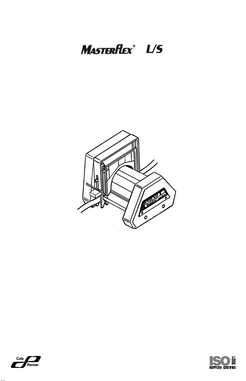
OP ER ATING MAN UAL
®
CAR TRIDGE
PUMP HEAD SYS TEM
Pump Head Models
07519-05 07519-06
Car tridge Models
Small: 07519-60
Large: 07519-50
Multi-channel peri stal tic pumps ac com mo date two sizes of snap-in tub ing
cartridges which pro vide bal anced, ad just able flow via in stantly change able
oc clu sion set ting. The sys tem mates with most ex ist ing MASTERFLEX
L/S® pump drives.
Cole-Parmer In stru ment Co.
625 East Bunker Court
Vernon Hills, Il li nois U.S.A. 60061-1844
800-MASTERFLEX (627-8373)
(847) 247-2929 (Fax)
www.masterflex.com
e-mail: techinfo@coleparmer.com
A-1299-0539
Edi tion 08
®
®
Page 2

Page 3

CON TENTS
Ti tle Page
SAFETY PRECAUTIONS .................................... ii
IN TRO DUC TION .......................................... 1
(1) Ap pli ca tion Data ..................................... 1
(2) Gen eral De scrip tion .................................. 2
IN STAL LA TION ........................................... 3
SETUP .................................................. 4
(1) Se lect Car tridges ..................................... 4
(2) Load Car tridges ...................................... 5
(3) Re tainer Ad just ment/Car tridge Re moval .................... 7
(4) Bi-Directional Pumping ................................. 7
OP ER A TION ............................................. 8
(1) Se lect Tubing and Pump Heads ......................... 8
(2) Se lect Pump Speed ................................... 9
(3) Ad just Oc clu sion Set tings on Car tridges .................... 9
MAIN TE NANCE ........................................... 11
Ser vice Parts .......................................... 11
SPEC I FI CA TIONS ......................................... 12
WAR RANTY ............................................. 13
PRO DUCT RE TURN ....................................... 13
TECH NI CAL AS SIS TANCE .................................. 13
®
AP PEN DIX A MASTERFLEX
AP PEN DIX B Car tridge Loading Ca pac ity ..................... B-1
L/S® Pump Drive Types ............ A-1
C-FLEX -Reg TM Con sol i dated Poly mer Tech nol ogies, Inc.
PHARMED, NORPRENE, TYGON -Reg TM Norton Co.
VITON -Reg TM DuPont Dow Elas to mers L.L.C.
Trade marks bear ing the ® sym bol in this pub li ca tion
are reg is tered in the U.S. and in other coun tries
These prod ucts are cov ered by one
or more of the fol low ing U.S. and
cor re spond ing for eign pat ents:
4,886,431 and 5,257,917
i
Page 4

SAFETY PRECAUTIONS
WARNINGS: Tubing break age may re sult in fluid be ing sprayed from
pump. Use ap pro pri ate mea sures to pro tect op er a tor
and equip ment.
Turn drive off be fore re mov ing or in stall ing car tridges.
Safety guards are pro vided to min i mize risk of fin gers
get ting caught be tween the roller mech a nism and the
base of the mod ule. How ever, be safe—Keep your fin gers away from these ar eas.
CAUTIONS: Ex ces sive oc clu sion can cause high pump tem per a -
tures and early tub ing and roller fail ure. Do not set
occlusion tighter than what is rec om mended in Ta ble #3.
Large Car tridge 07519-50 should not be used with
microbore tub ing—may re sult in pre ma ture tub ing
failure.
WARNING: PRO DUCT USE LIM I TA TION
These prod ucts are not de signed for, nor in tended for use in pa tient
con nected ap pli ca tions; in clud ing, but not lim ited to med i cal and den tal use, and ac cord ingly have not been sub mit ted for FDA approval.
ii
Page 5

IN TRO DUC TION
The in struc tions in this man ual are task-oriented for easy ref er ence. You
can go di rectly to a par tic u lar sec tion and quickly find the an swers. Ap pen dix A and B list MASTERFLEX
®
L/S® pump drive types that can be used
with this sys tem.
Pump Heads
MODEL TYPE
Model 07519-05
Model 07519-06
3-Roller, 4 or 8 Chan nel
4-Roller, 4 or 8 Chan nel
Car tridges
MODEL TYPE
Model 07519-50
Model 07519-60
These car tridge pumps are de signed to pro vide up to 8 si mul ta neously
driven pump chan nels and in cor po rate the fol low ing fea tures.
• Si mul ta neous dis pens ing into an 8 bank set of test tubes with one set-up
and pump cy cle.
• The four-roller de sign pro vides re duced pul sa tion.
Large
Small
(1) Ap pli ca tion Data
The Car tridge Pump Sys tem is de signed for multi-channel use where close oc clu sion con trol of a va ri ety of dif fer ent flows is re quired. All stan dard and many
spe cial tub ing sizes and ma te ri als can be used, de liv er ing from .015 mL/min to
2 L/min.
1
Page 6
(2) Gen eral De scrip tion
Each Pump Head Sys tem is com posed of a heavy-duty Pump Head and
two sizes of snap-in tub ing car tridges, each with in di vid u ally ad just able oc clu sion set tings. The oc clu sion “wedge” de sign pro vides ac cu rate and more
bal anced flow con trol.
The Pump Heads con tain ei ther three or four roll ers. All mod els can op er ate
with a va ri ety of tub ing and with ei ther the small or the large car tridges.
®
The Pump Head quickly mounts to most ex ist ing MASTERFLEX
L/S
Pump Drive types (see Ap pen dix A and B).
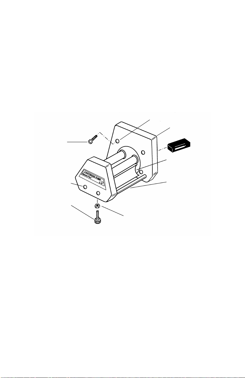
MOUNTING
HOLES
TANG (REAR OF
PUMP HEAD)
®
MOTOR MOUNTING
SCREWS (4)
SCREWDRIVER
CLEARANCE HOLE
ADJUSTABLE
FOOT
LOCKNUT
FIGURE 1 PUMP MOUNTING
SAFETY
GUARD
CARTRIDGE
MOUNTING
RODS
BOOT
2
Page 7

IN STAL LA TION
Tool Re quired: Long-Shaft Phil lips Head Screw driver (pro vided).
®
Mount the Pump Head to a MASTERFLEX
1. In stall the plas tic Boot over the tang at the end of pump shaft (Fig ure 1).
This Boot pre vents metal-to-metal con tact, and thus re duces noise.
This boot should be in spected and re placed when worn or at 500-hour
in ter vals.
NOTE: The boot with closed ends (A-3480) will fit most drives. Use of
the boot with open ends (A-3514) may be re quired on some drives.
Both boots are sup plied with the pump.
A-3480
L/S® Pump Drive as fol lows:
2.
A-3514
FIGURE 2 PLASTIC BOOTS
Con nect the Pump to Drive by align ing the tang on Pump Head (in clud ing in stalled boot) with the slot in the mo tor Drive shaft.
3. At tach Pump Head to drive unit with four screws (pro vided) us ing the
long-shaft Phil lips screw driver (also pro vided).
WARNING: Tubing break age may re sult in fluid be ing sprayed from
pump. Use ap pro pri ate mea sures to pro tect op er a tor
and equip ment.
4. If the Pump Head re quires sup port, in stall the ap pro pri ate length sup -
port screw with plas tic foot and locknut (three pro vided). Level the
Pump Head with the drive unit by ad just ing the foot. Tighten the locknut
against the bot tom of the pump body.
3
Page 8

SETUP
Two car tridge sizes (0.72 in and 0.36 in thick) (see Fig ure 3) ac com mo date
a broad range of tub ing sizes as noted in the “Car tridge Loading Ca pac ity”
chart (see Ap pen dix B).
FIGURE 3 SMALL AND LARGE CARTRIDGES
(1) Se lect Car tridges
NOTE: These Pump Heads are de signed to work with the Model 07519-50
and 07519-60 Car tridges. Do not use Model 07519-55 or 07519-65 Car tridges, which are de signed for dif fer ent Pump Heads.
De pending on which Pump Head is used, up to four large or eight small tub ing car tridges can be teamed up with the Pump Head. But there is a limit de pend ing on avail able drive power and pump load. For full tub ing flow rates at
0 psi, the ta ble in Ap pen dix B show car tridge ca pac i ties for all the stan dard
MASTERFLEX
for de scrip tion of drive types). Car tridge sizes can be in ter mixed as long as
the to tal load does n’t ex ceed the drive ca pa bil ity.
The small Car tridge is de signed to de liver op ti mum per for mance with
0.9 mm (0.035 in) wall, Microbore tub ing up to 2.79 mm (0.110 in) I.D., and
will ac com mo date MASTERFLEX
the three- or the four-roller Pump Head.
The large Car tridge is de signed to de liver op ti mum per for mance with
MASTERFLEX
®
25 with ei ther the three- or the four-roller Pump Head. Large Car tridges are
L/S
fac tory set to mid-range of the “Mflex” scale.
Use only MASTERFLEX
MASTERFLEX
®
L/S® tub ing sizes and drive Types I, II, III (see Ap pen dix A
®
L/S® 13 or L/S® 14 tub ing, used with ei ther
®
L/S® pre ci sion tub ing sizes L/S® 14, L/S 16, L/S 17, L/S 18 and
®
®
pumps to en sure op ti mum per for mance.
pre ci sion and Microbore tub ing with
Use of other tub ing may void ap pli ca ble war ran ties.
4
Page 9

(2) Load Car tridges
Easy, snap-in mount ing and quick-release re moval come with a Car tridge
sys tem—no tools re quired. Since the Car tridges func tion uni formly in ei ther
di rec tion, car tridge ori en ta tion is not im por tant. How ever, you may wish to
al ter nate Car tridges so that the Ad just ment Knob on each is eas ier to turn
when sev eral small car tridges are mounted close to gether.
WARNING: Turn drive off be fore re mov ing or in stall ing Car tridges.
Safety guards are pro vided to min i mize risk of fin gers
get ting caught be tween the roller mech a nism and the
base of the mod ule. How ever, be safe—Keep your fin gers away from these ar eas.
CAU TION: Large Car tridge 07519-50 should not be used with
microbore tub ing—may re sult in pre ma ture tub ing
fail ure.
5
Page 10

With the drive stopped, fol low this pro ce dure to in stall Car tridges.
1. Turn the Ad just ment Knob (see Fig ure 4) coun ter clock wise to max i -
mum open.
OCCLUSION SETPOINT SCALE
ADJUSTMENT
KNOB
OCCLUSION
WEDGES
TUBING RETAINER
BUTTONS
LATCH
HOOK LEG
LATCH LEG
TAB
FIGURE 4 CARTRIDGE ASSEMBLY
2. Push the two Tubing Re taining But tons in and up to ac cept tub ing.
NOTE: The Re tainer But ton lo cated on the Ad just ment Knob side of the
Car tridge is a loose com po nent and may fall out. To re as sem ble, push it
back into place while press ing in the but ton.
3. Se lect tub ing and place in Car tridge (see Fig ure 5A).
4. At tach the Hook Leg of Car tridge to one of the Sup port Rods (see Fig -
ure 5B).
5. Swing the Car tridge with tub ing over the (other side of the) ro tor and
push down on tab un til the Latch snaps closed. (See Fig ure 5C.)
6. Re strain the tub ing on the in let side of pump by push ing the Tubing Re -
tainer But ton in and down firmly.
5A
5B
FIGURE 5 TUBE AND CARTRIDGE LOADING
6
5C
Page 11

7. Lightly pull the tub ing at the out let side to re move slack: then push its
Tubing Re tainer But ton in and down . This should se cure the tub ing.
8. Ad just the oc clu sion set ting. (See OP ER A TION sec tion.) For a nom i nal
set ting, turn ad just ment screw un til in side edge of the wedge is aligned
mid way be tween #3 and #4 on the la bel.
9. Start drive slowly. If tub ing creeps through pump, go to sec tion 3, Re -
tainer Ad just ment.
(3) Re tainer Ad just ment/Car tridge Re moval
There are a few com bi na tions of tub ing sizes and ma te ri als that may re quire
an ad di tional fine ad just ment of the Tubing Re tainers to pre vent the tub ing
from creep ing through the head. If this prob lem should oc cur, use the fol low ing pro ce dure to elim i nate the tub ing creep:
1. Set drive to “0” and turn drive OFF.
2. Push down on latch side of car tridge and pull latch out ward to un hook
from rod.
3. Pivot car tridge up wards and un hook Hook Leg from rod and re move
car tridge.
4. Push both tub ing re tainer but tons down one notch.
5. Re in stall car tridge by first hook ing Hook Leg on rod, then, while piv ot -
ing car tridge down wards, gently stretch sec tion of tub ing ex it ing car tridge on latch side and hook latch on rod.
6. Turn drive ON, slowly in crease drive speed and check for tub ing creep.
7. If tub ing creep per sists, re peat steps 1 through 6 again or un til the tub -
ing no lon ger creeps through the pump head.
NOTE: Over-adjustment of tub ing re tain ers may in hibit fluid flow.
(4) Bi-Directional Pumping
Fluids can be pumped into and back out of con tain ers by re vers ing the
drive. On drives that can not be re versed, use lon ger tub ing lengths and sim ply re verse the loaded car tridge.
WARNING: Tubing break age may re sult in fluid be ing sprayed from
pump. Use ap pro pri ate mea sures to pro tect op er a tor
and equip ment.
7
Page 12

OP ER A TION
This sec tion de scribes the tub ing oc clu sion set ting pro ce dures for ob tain ing
de sired per for mance.
(1) Se lect Tubing and Pump Heads
Use ta bles 1 and 2 as a guide to se lect the tub ing and Pump Head to pro vide
the re quired sin gle chan nel flow rate.
TABLE 1 SMALL CARTRIDGE PUMP FLOW RATES—07519-60
Tubing ID, MM>
Tubing ID, Inches>
Pump
Ro tor
Head
rpm Units
3-Roller6 to
3-Roller1 to
4-Roller6 to
4-Roller1 to
MICROBORE TUBING (mm ID)
0.89 1.42 2.06 2.79
FLOW RATES
mL/min
600
mL/min
100
mL/min
600
mL/min
100
0.44
0.074
7.4
0.44
0.074
7.4
to
44
to
to
44
to
1.06
0.18
1.06
0.18
0.37
0.37
2.2
to
220
to
37
2.2
to
220
to
37
to
106
to
18
to
106
to
18
0.63
0.63
MASTERFLEX
3.8
to
380
to
63
3.8
to
380
to
63
®
L/S
13 L/S® 14
0.36
to
36
0.06
to
6
0.32
to
32
0.05
to
5
®
TABLE 2 LARGE CARTRIDGE PUMP FLOW RATES—07519-50
MASTERFLEX® L/S® Tubing
Tubing ID, MM>
Tubing ID, Inches>
Pump
Head
3-Roller
3-Roller
4-Roller
4-Roller
Ro tor
rpm
to
600
to
100
to
600
to
100
6
1
6
1
Units
mL/min
mL/min
mL/min
mL/min
®
L/S
14 L/S® 16 L/S® 25 L/S® 17* L/S® 18*
FLOW RATES
0.21
0.19
1.3
to
130
to
21
1.2
to
115
to
19
0.68
4.8
to
480
0.8
to
80
4.1
to
410
to
68
1000
170
830
140
10
to
1.7
to
8.3
to
1.4
to
1700
280
13.7
1370
230
17
to
2.8
to
to
2.3
to
L/S® TUBING
1.3
to
130
0.21
to
21
1.2
to
115
0.19
to
19
23
to
2300
3.8
to
380
18
to
1800
3.0
to
300
*NOTE: Only Sil i cone and C-FLEX® tub ing are rec om mended for L/S® 17
and L/S
®
18.
8
Page 13

(2) Se lect Pump Speed
Se lect fixed speed drive or ad just speed of vari able speed drive to pro vide
de sired nom i nal flow rate within the ro tor rpm speed range shown for the
pump model se lected.
(3) Ad just Oc clu sion Set tings on Car tridges
CAU TION: Ex ces sive oc clu sion can cause high pump tem per a -
tures and early tub ing and roller fail ure. Do not set oc clu sion tighter than what is rec om mended in Ta ble #3.
NOTE: With large and small car tridges, the scale iden ti fied as “Mflex” pro -
®
vides nom i nal oc clu sion for MASTERFLEX
L/S® pre ci sion tub ing at the
#3 – #4 set ting.
With a multi-channel car tridge sys tem, flow rate, pres sure sen si tiv ity and
tub ing life can be fine-tuned—even while the pump is run ning. No lost time,
and with op er at ing speeds up to 600 rpm, you get higher max i mum flows
with the same size tub ing.
Fig ure 6 (large and small car tridge) shows the wedges ad justed at #3 on the
oc clu sion setpoint scale for the MASTERFLEX
Rotate knob to
adjust occlusion
®
tub ing.
Occlusion
Wedge
1 High Occlusion
5 Low Occlusion
FIGURE 6 OCCLUSION INDICATIONS FOR THE
MASTERFLEX
®
TUBING
The Ad just ment Knob (see Fig ure 6) con trols a screw mech a nism to move
the oc clu sion wedges. Once a Car tridge is ad justed to a de sired set ting for a
par tic u lar ap pli ca tion, there is no need to re set. Or, you can re cord set tings
and quickly re pro duce them at a later time.
9
Page 14

(a) Nor mal Oc clu sion Set tings
The fol low ing ta ble shows the ap pro pri ate oc clu sion set tings to pro vide sat is fac tory per for mance for var i ous tub ing sizes. (For op ti mum oc clu sion set tings, see fol low ing sec tion.)
TABLE 3 RECOMMENDED OCCLUSION SETTINGS
Tubing Large Car tridge
Mflex Scale
Microbore N/A #1 – #2
MASTERFLEX® L/S®
Pre ci sion
#3 – #4 #3 – #4
Small Car tridge
Mflex Scale
(b) Oc clu sion Set ting Pro ce dure:
1. Se lect the rec om mended oc clu sion value from the ta ble.
2. Turn the Ad just ment Knob to align the in side edge of the white Wedge
with the scale num ber. (Clock wise ro ta tion in creases the oc clu sion.)
(c) Op ti mized Oc clu sion Set tings
Some ap pli ca tions re quire ad di tional fine-tuning of the oc clu sion set ting to
vary the flow rate for a par tic u lar tub ing to re duce flow vari a tions caused by
changes in sys tem pres sure, or to in crease tub ing life.
1. Ad just the Oc clu sion Wedges as de scribed in the pre ced ing ta ble.
2. Re fine this set ting, de pend ing on your ob jec tives:
NOTE: To Max i mize Tubing Life
While run ning the pump, sim ply re duce the ad justed oc clu sion set ting by
turn ing the Ad just ment Knob coun ter clock wise to move the wedges to a
higher setpoint scale num ber (to ward 5). Con tinue turn ing the knob coun ter clock wise un til the flow drop-off or the pres sure sen si tiv ity be comes un ac cept able, then turn knob slightly clock wise.
NOTE: To Re duce or Elim i nate Flow Drop-Off Rate with Pres sure
Fluc tu a tions
While run ning the pump, al ter nate the backpressure be tween the ex pected
high and low val ues and in crease the ad justed oc clu sion set ting. Turn the
Ad just ment Knob clock wise to move the wedges to a lower setpoint scale
num ber (to ward 1) un til the flow drop-off is min i mized.
NOTE: To Fine-Adjust the Flow Rate
In crease or de crease the oc clu sion value to vary the flow.
10
Page 15

MAIN TE NANCE
No main te nance re quired. Wipe Pump with a clean cloth and a mild de ter gent. Never im merse nor use ex ces sive fluid.
Ser vice Parts:
Boot, A-3480, see Fig ure 2
Boot, A-3514, see Fig ure 2
Phil lips screw driver, A-3624
Screw, 8-32, 1 in Pan-PH, B-1079-0412
Level Feet As sem bly, A-4128-0002, (2 in)
Level Feet As sem bly, A-4128-0003, (1-1/4 in)
Level Feet As sem bly, A-4128-0004, (1-5/8 in)
11
Page 16

SPEC I FI CA TIONS
PUMP HEAD
Speed Range: 0 to 600 rpm
Torque Load: 5 oz-in (max.) with no car tridges
Op er ating Tem per a ture Range: 0° to 40°C (32°F to 104°F)
Stor age Tem per a ture Range: −40°C to 110 °C (−40 °F to 230°F)
Con struc tion and Fi ber glass-reinforced polysulfone
Chem i cal Re sis tance: hous ing; stain less steel, an od ized
alu mi num, sealed stain less steel
ball bear ings and Buna N
safety guard.
CAR TRIDGES
Con struc tion: Du ra ble polycarbonate frame with
filled ny lon and acetal com po nents.
An od ized alu mi num ad just ment
knob on stain less steel screw.
Di men sions:
Large 4 in Tall x 5 in W x 0.72 in Thick
(102 mm x 127 mm x 18.3 mm)
Small 4 in Tall x 5 in W x 0.36 in Thick
(102 mm x 127 mm x 9.1 mm)
12
Page 17

WAR RANTY
Use only MASTERFLEX® pre ci sion and Microbore tub ing with
MASTERFLEX
tub ing may void ap pli ca ble war ran ties.
The man u fac turer war rants this prod uct to be free from sig nif i cant de vi a tions from pub lished spec i fi ca tions. If re pair or ad just ment is nec es sary
within the war ranty pe riod, the prob lem will be cor rected at no charge if it is
not due to mis use or abuse on your part as de ter mined by the man u fac turer.
Re pair costs out side the war ranty pe riod, or those re sult ing from prod uct
mis use or abuse, may be in voiced to you.
The war ranty pe riod for this prod uct is noted on the war ranty card.
®
pumps to en sure op ti mum per for mance. Use of other
PRO DUCT RE TURN
To limit charges and de lays, con tact the seller or man u fac turer for au tho ri za tion and ship ping in struc tions be fore re turn ing the prod uct, ei ther within
or out side of the war ranty pe riod. When re turn ing the prod uct, please state
the rea son for the re turn. For your pro tec tion, pack the prod uct care fully and
in sure it against pos si ble dam age or loss. Any dam ages re sult ing from im proper pack ag ing are your re spon si bil ity.
TECH NI CAL AS SIS TANCE
If you have any ques tions about the use of this prod uct, con tact the man u fac turer or au tho rized seller.
13
Page 18

AP PEN DIX A
MASTERFLEX
®
L/S® PUMP DRIVE TYPES
FOR USE WITH CAR TRIDGE PUMP SYS TEMS
Max
rpm
600
120
600 0.05 90 II
100 0.1 360 III
Power
(hp)
0.1
0.05
Torque
oz-in
180
180
Drive
Type
I
Note: Check Max rpm and Power of the Drive or use the Torque rat ing to
de ter mine the Drive Type.
A-1
Page 19

AP PEN DIX B
CAR TRIDGE LOADING CA PAC ITY
Car tridge
Size
Small
Large
Tubing
Size
Microbore
.89 mm
Microbore
1.42 mm
Microbore
2.06 mm
Microbore
2.79 mm
L/S® 13
L/S® 14
®
L/S
L/S® 16
L/S® 25
L/S® 17
L/S® 18 Soft 43 4 2 4
14
Tubing
Ma te rial*
Soft
Stiff
Soft
Stiff
Soft
Stiff
Soft
Stiff
Soft 10 8 8 8
Stiff 26 7 3 8
Soft 10 8 8 8
Stiff 31 6 3 8
Soft 10 4 4 4
Stiff 31 4 3 4
Soft 14 4 4 4
Stiff 31 4 3 4
Soft 43 4 2 4
Stiff 80 2 1 4
Soft 43 4 2 4
Stiff 80 2 1 4
Torque**
(Avg. oz-in)
‡
‡
‡
‡
‡
‡
‡
‡
Max. No. of Car tridges
Drive
Type I
8 8 8
7 3 8
8 8 8
- - -
8 8 8
7 3 8
8 8 8
7 3 8
Drive
Type II
Drive
Type III
*Soft ma te ri als are sil i cone and C-FLEX®.
Stiff ma te ri als are NORPRENE
®
, TYGON® and VITON
®
(fluoroelastomer).
** Torque re quire ments are the same for both 3- and 4-roller ro tor pump
heads.
‡Torque data not avail able.
Printed in U.S.A.
B-1
080900
 Loading...