

Page 1

OPERATING MANUAL
CARTRIDGE PUMP HEAD
SYSTEM
NOTICE D’UTILISATION
SYSTÈME DE TÊTE DE
POMPE À CARTOUCHES
BEDIENUNGSANLEITUNG
PUMPENKOPFSYSTEM
MIT SCHLAUCHKASSETTEN
MANUAL DE OPERACIÓN
SISTEMA DE CABEZA DE
07519-05 Pump Head with 07519-70 Large Cartridge
Tête de pompe 07519-05 à cartouche épaisse 07519-70
Pumpenkopf 07519-05 mit großer Schlauchkassette 07519-70
Cabeza de bomba 07519-05 con cartucho grande 07519-70
Testa pompante 07519-05 con cartuccia grande 07519-70
Model Nos.
Modèles n°
Modellnummern
Números de modelo
Modelli n°
07519-05
07519-06
BOMBAS DE CARTUCHOS
MANUALE DI ISTRUZIONI
SISTEMI CON TESTA
POMPANTE A CARTUCCE
Cartridge Small
Cartouche mince
Kleine Schlauchkassette
Cartucho pequeños
Cartucce piccole
07519-80
Cartridge Large
Cartouche épaisses
e Schlauchkassette
Gro
Cartucho grandes
Cartucce grandi
®
(US & Canada only) Toll Free 1-800-MASTERFLEX • 1-800-637-3739
(Outside US & Canada) 1-847-549-7600 • 1-847-381-7050
www.masterflex.com • techinfo@masterflex.com
07519-70
A-1299-0904B
Edition 08
Page 2

PUMP FOR LIQUIDS
ORIGINAL INSTRUCTIONS
Page 3

CONTENTS
Title Page
SAFETY PRECAUTIONS . . . . . . . . . . . . . . . . . . . . . . . . . . . . . . . . . . . . . . . . . . . . . . . . . . . . . . . . . . . . . . . . 2
INTRODUCTION . . . . . . . . . . . . . . . . . . . . . . . . . . . . . . . . . . . . . . . . . . . . . . . . . . . . . . . . . . . . . . . . . . . . . . 3
(1) Application Data. . . . . . . . . . . . . . . . . . . . . . . . . . . . . . . . . . . . . . . . . . . . . . . . . . . . . . . . . . . . . . . . . . 3
(2) General Description. . . . . . . . . . . . . . . . . . . . . . . . . . . . . . . . . . . . . . . . . . . . . . . . . . . . . . . . . . . . . . . . 3
INSTALLATION . . . . . . . . . . . . . . . . . . . . . . . . . . . . . . . . . . . . . . . . . . . . . . . . . . . . . . . . . . . . . . . . . . . . . . . 4
SETUP . . . . . . . . . . . . . . . . . . . . . . . . . . . . . . . . . . . . . . . . . . . . . . . . . . . . . . . . . . . . . . . . . . . . . . . . . . . . . . 5
(1) Select Cartridges . . . . . . . . . . . . . . . . . . . . . . . . . . . . . . . . . . . . . . . . . . . . . . . . . . . . . . . . . . . . . . . . . 5
(2) Load Cartridges . . . . . . . . . . . . . . . . . . . . . . . . . . . . . . . . . . . . . . . . . . . . . . . . . . . . . . . . . . . . . . . . . . 5
(3) Cartridge Removal. . . . . . . . . . . . . . . . . . . . . . . . . . . . . . . . . . . . . . . . . . . . . . . . . . . . . . . . . . . . . . . . . 7
(4) Bi-Directional Pumping . . . . . . . . . . . . . . . . . . . . . . . . . . . . . . . . . . . . . . . . . . . . . . . . . . . . . . . . . . . . . 7
(5) Partial Bank Pumping . . . . . . . . . . . . . . . . . . . . . . . . . . . . . . . . . . . . . . . . . . . . . . . . . . . . . . . . . . . . . . 7
OPERATION . . . . . . . . . . . . . . . . . . . . . . . . . . . . . . . . . . . . . . . . . . . . . . . . . . . . . . . . . . . . . . . . . . . . . . . . . 8
(1) Select Tubing and Pump Heads . . . . . . . . . . . . . . . . . . . . . . . . . . . . . . . . . . . . . . . . . . . . . . . . . . . . . 8
(2) Select Pump Speed. . . . . . . . . . . . . . . . . . . . . . . . . . . . . . . . . . . . . . . . . . . . . . . . . . . . . . . . . . . . . . . 9
(3) Adjust Occlusion Settings on Cartridges . . . . . . . . . . . . . . . . . . . . . . . . . . . . . . . . . . . . . . . . . . . . . . . 9
MAINTENANCE. . . . . . . . . . . . . . . . . . . . . . . . . . . . . . . . . . . . . . . . . . . . . . . . . . . . . . . . . . . . . . . . . . . . . . 10
Service Parts. . . . . . . . . . . . . . . . . . . . . . . . . . . . . . . . . . . . . . . . . . . . . . . . . . . . . . . . . . . . . . . . . . . . . . 10
SPECIFICATIONS . . . . . . . . . . . . . . . . . . . . . . . . . . . . . . . . . . . . . . . . . . . . . . . . . . . . . . . . . . . . . . . . . . . . 10
WARRANTY. . . . . . . . . . . . . . . . . . . . . . . . . . . . . . . . . . . . . . . . . . . . . . . . . . . . . . . . . . . . . . . . . . . . . . . . . 11
PRODUCT RETURN . . . . . . . . . . . . . . . . . . . . . . . . . . . . . . . . . . . . . . . . . . . . . . . . . . . . . . . . . . . . . . . . . . 11
TECHNICAL ASSISTANCE. . . . . . . . . . . . . . . . . . . . . . . . . . . . . . . . . . . . . . . . . . . . . . . . . . . . . . . . . . . . . 11
APPENDIX A MASTERFLEX
®
L/S®Pump Drive Types. . . . . . . . . . . . . . . . . . . . . . . . . . . . . . . . . . . . . . . . . 12
APPENDIX B Cartridge Loading Capacity. . . . . . . . . . . . . . . . . . . . . . . . . . . . . . . . . . . . . . . . . . . . . . . . . . . 12
C-FLEX — Reg TM Consolidated Polymer Technologies, Inc.
C-FLEX, PHARMED, NORPRENE, TYGON—Reg TM Saint-Gobain Performance Plastics Corp.
SANTOPRENE — Reg TM AES.
VITON — Reg TM E.I. duPont DeNemours & Co.
Trademarks bearing the ® symbol in this publication are registered in the U.S. and in other countries.
1
Page 4
SAFETY PRECAUTIONS
WARNINGS:Tubing breakage may result in fluid being sprayed from pump. Use appropriate measures to pro
tect operator and equipment.
Turn off drive beforeremoving orinstalling Cartridges. Safetyguards areprovided tominimize risk
of fingers getting caught between the roller mechanism and the base of the module. However, be
safe—Keep your fingers away from these areas.
CAUTIONS: Excessive occlusion can cause high pump temperaturesand early tubing and roller failure. Do not
set occlusion tighter than what is recommended in Table 4.
Use only tubing/cartridge combinations defined by Tables 1, 2, and 3. Use of other combinations
could cause malfunction or damage to the pump.
Not using the BOOT will damage the pump.
Explanation of Symbols
CAUTION: Risk of Danger. Consult Operator’s manual for nature of hazard and corrective actions.
CAUTION: Risk of crushing. Keep fingers away from rotor while pump is in operation. Stop pump before load
ing or unloading tubing.
-
-
WARNING: PRODUCT USE LIMITATION
These products are not designed for, nor intended for use in, patient-connected applications, including, but not
limited to, medical and dental use and, accordingly, have not been submitted for FDA approval.
2
Page 5

INTRODUCTION
The instructions in this manual are task-oriented for easy reference. You can go directly to a particular section and
quickly find the answers. Appendix A and B list MASTERFLEX
®
L/S®pump drive types which can be used with this
system.
Pump Heads
MODEL TYPE
Model 07519-05
Model 07519-06
3-Roller, 4 or 8 Channel
4-Roller, 4 or 8 Channel
Cartridges
MODEL TYPE
Model 07519-70
Model 07519-80
These Cartridge Pumps are designed to provide up to 8 simultaneously driven pump channels and incorporate the fol
lowing features.
Simultaneous dispensing into 8 separate containers with one set-up and pump cycle.
·
The four-roller design provides reduced pulsation.
·
(1) Application Data
Large
Small
-
The Cartridge Pump System isdesigned for multi-channeluse where closeocclusion control of avariety of differentflows
is required. Tubing found in Table 3 may be used to deliver from .074 to 1700 mL/min.
(2) General Description
Each Pump Head Systemis composedof aheavy dutyPump Headand twosizes ofsnap-in tubingCartridges, eachwith
individually adjustable occlusion settings.The occlusion“wedge” designprovides accurateand morebalanced flowcontrol.
The Pump Heads contain either three or four rollers. Both models can operatewith a variety oftubing and with eitherthe
small or the large Cartridges.
®
The Pump Head quickly mounts to most existing MASTERFLEX
L/S®Pump Drive types (see Appendix A and B).
3
Page 6

INSTALLATION
Tool Required: Allen Key (provided).
Mount the Pump Head to a MASTERFLEX
1. Install the plastic Bootover the tang at the end of pump shaft,(Figure 1). This Boot prevents metal-to-metal contact,
and thus reduces noise. This Boot should be inspected and replaced when worn or at 500 hour intervals.
CAUTION: Not using the boot will damage the pump.
NOTE: The boot with closed ends (A-3480) will fit most drives.Use of the bootwith open ends (A-3514) may be required
on some drives. Both boots are supplied with the pump.
2. Connect the Pump to Drive by aligning the tang on Pump Head, (including installed boot) with the slot in the motor
Drive shaft.
3. Attach Pump Head to drive unit with four screws (provided) using the Allen Key (also provided).
WARNING: Tubing breakage may result in fluid being sprayed from pump. Use appropriate measures to pro
tect operator and equipment.
4. If the Pump Head requires support, install the appropriate length support screw with plastic foot and locknut (three
provided). Level the Pump Head withthe drive unitby adjusting thefoot. Tighten thelocknut against the bottomof the
pump body.
®
L/S®Pump Drive as follows:
-
FIGURE 1 PUMP MOUNTING
A-3480
FIGURE 2 PLASTIC BOOTS
4
A-3514
Page 7

SETUP
Two Cartridge sizes (0.72 in and 0.36 in thick) (see Figure 3) accommodate a broad range of tubing sizes as noted in
Tables 1 and 2.
FIGURE 3 SMALL AND LARGE CARTRIDGES
(1) Select Cartridges
NOTE: These Pump Heads are designed to work with the Model 07519-70 and 07519-80 Cartridges. Do not use Model
07519-75 or 07519-85 Cartridges, which are designed for different Pump Heads.
Depending on which Pump Head is used, up to four large or eight small tubing Cartridges can be teamed up with the
Pump Head. But there is a limit depending on available drive powerand pump load. For full tubing flow rates at 0 psi, the
table in Appendix Bshows cartridge capacitiesaccording totubing sizeand drive Type(see AppendixA fordescription of
Drive Types). Cartridge sizes can be intermixed as long as the total load does not exceed the drive capability.
The small Cartridge is designedto operate with MASTERFLEX
accommodate specially designedMicrobore TubingSets (.9 mm wall — seeTables 1 and 3).The small Cartridge can be
used with either the three- or the four-roller Pump Head.
The large Cartridge is designed to operate withMASTERFLEX
®
L/S
17, with either the three- or four-roller Pump Head (see Tables 2 and 3).
®
precision tubing sizes L/S®13 and L/S®14, and will also
®
L/S®precision tubing sizes L/S®14, L/S®16, L/S®25 and
Use only MASTERFLEX Precision Tubing and Microbore Tubing Sets with MASTERFLEX Pumps to ensure
optimum performance. Use of other tubing may void applicable warranties.
(2) Load Cartridges
Easy, snap-in mounting and quick-release removal come with a Cartridge system—no tools required. Since the Car
tridges function uniformly in either direction, Cartridge orientation is not important. However, you may wish to alternate
Cartridges so that the Adjustment Knob on each is easier to turn when several small Cartridges are mounted close to
gether.
WARNING: Turn offdrive beforeremoving or installingCartridges. Safetyguards areprovided tominimize risk
of fingers getting caught between the roller mechanism and the base of the module. However, be
safe—Keep your fingers away from these areas.
CAUTION: Use only tubing/cartridge combinations defined by Tables 1, 2, and 3. Use of other combinations
could cause malfunction or damage to the pump.
With the drive stopped, follow this procedure to install Cartridges.
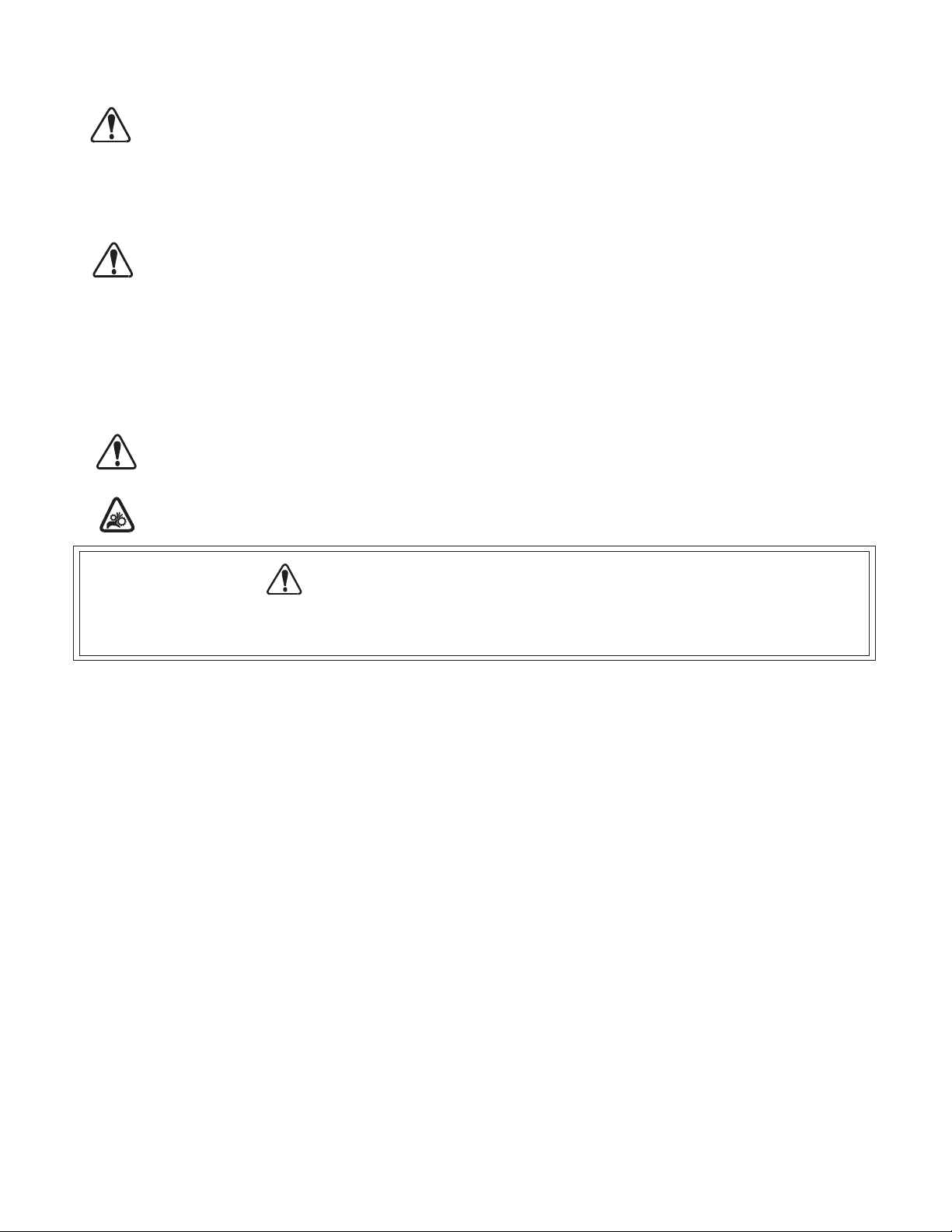
1. Turn the Occlusion Adjustment Knob (see Figure 4) counterclockwise to maximumopen. This step isnot necessary
when the occlusion is setat the factory setting or if the occlusion has already been setappropriately during previous
pumping.
2. Set the Tubing Retainer according to tubing size (see Figure 6A)when using the largeCartridge. No retainer adjust
ment is required when using the small Cartridge. (Note: The retainer button located on the Occlusion Adjustment
Knob-side of the large Cartridge isa loose component and may fall out. To reassemble, push it back into placewhile
pressing in the button.)
-
-
-
5
Page 8
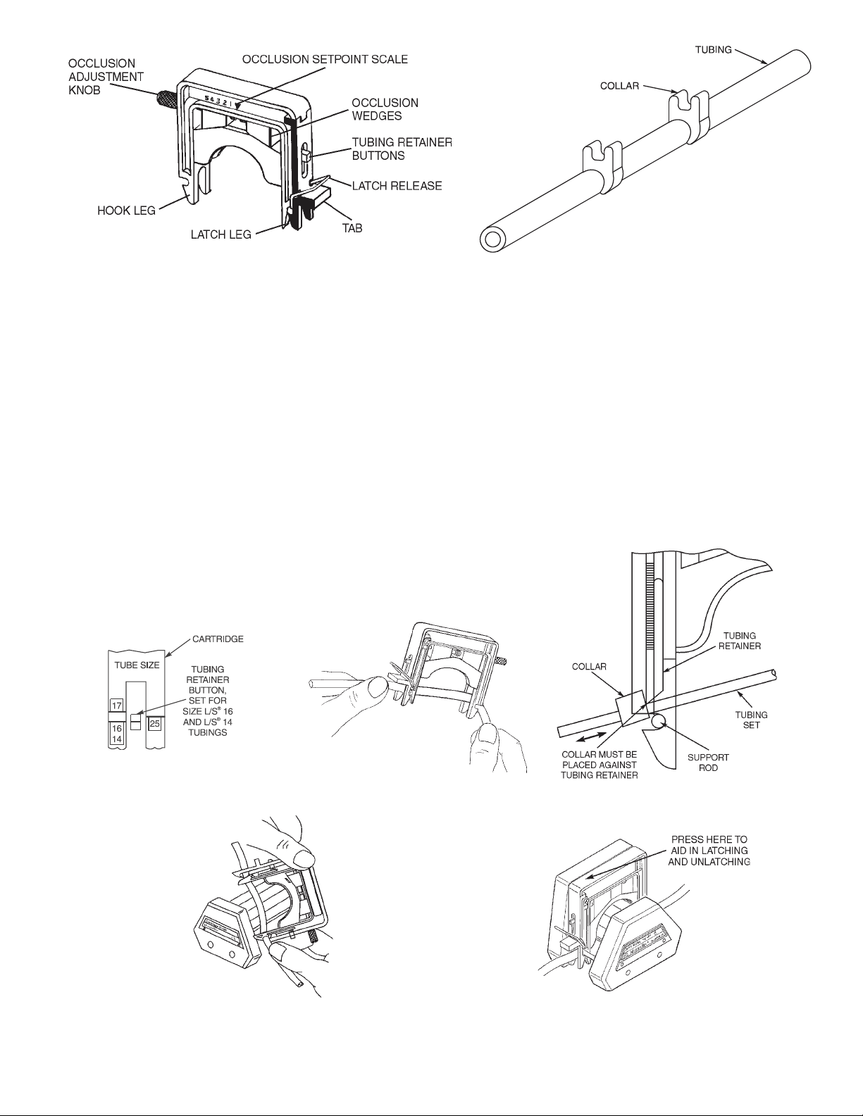
FIGURE 4 CARTRIDGE ASSEMBLY
3. Select tubingand place in Cartridge (see Figure 6B).If using a Microbore TubingSet (see Figure 5), placethe Collar
up against the Tubing Retainer (see Figure 6C) on both sides of the Cartridge.
4. Attach the Hook Leg of the Cartridge onto one of the Support Rods while holding the tubing between the Cartridge
legs and against the Tubing Retainer (see Figure 6D).
5. Swing the Cartridge with the tubing over the rotor and push down on the Tab (see Figure 4) until the Latch snaps
closed. (See Figure 6E.) Note: Depress the Cartridge as required in the location indicated in Figure 6E to facilitate
latching and unlatching.
6. Lightly pull the tubing at the outlet and inlet to remove the slack when using continuous tubing. No slack removal is
required when using a Microbore Tubing Set.
7. Adjust the occlusion setting (see OPERATION section). For a nominal setting with MASTERFLEX tubing, turn adjustment screw until inside edge of the wedge is aligned midway between #3 and #4 on the label.
FIGURE 5 MICROBORE TUBING SET
6A
6B
6D
FIGURE 6 TUBING AND CARTRIDGE LOADING
6
6C
6E
Page 9

(3) Cartridge Removal
Follow this procedure to unload the Cartridge.
1. Turn the Drive OFF.
2. Push down on latch side of Cartridge (see Figure 6E) and pull Latch Leg outward to unhook from rod. The Latch
Release (see Figure 4) can be depressed to aid in this process as desired.
3. Pivot Cartridge upwards and unhook Hook Leg from rod and remove Cartridge.
(4) Bi-Directional Pumping
Fluids can be pumped into and back out of containers byreversing the drive. Ondrives that cannot be reversed, use lon
ger tubing lengths and simply reverse the loaded Cartridge.
WARNING: Tubing breakage may result in fluid being sprayed from pump. Use appropriate measures to pro
tect operator and equipment.
(5) Partial Bank Pumping
The Pump can be operated with either a partial or a full bank of Car
tridges. There is an elastic, VITON
®
fluoroelastomer O-ring on each
of the two metal rods of the pump (see Figure 7) that holds the Car
-
tridges in place on the pump. These O-rings should be adjusted as
follows. If the pump is partially loaded with Cartridges, slide the
O-rings along the rods, up against the front of the outermost Car
tridge, to keep it in place(note position A, for example, in Figure 7). If
the pump is fully loaded with Cartridges, slide the O-rings to the front
of the pump as far as possible (note position B in Figure 7).
FIGURE 7 O-RING POSITION
-
-
7
Page 10

OPERATION
This section describes the procedures for obtaining the desired performance.
(1) Select Tubing and Pump Heads
Use Tables 1, 2, and 3to select thetubing, Cartridge, andPump Head toprovide the required singlechannel flow rate.
CAUTION: Use only tubing/cartridge combinations defined by Tables 1, 2, and 3. Use of other combinations
could cause malfunction or damage to the pump.
TABLE 1 SMALL CARTRIDGE FLOW RATES—07519-80
®
MICROBORE TUBING (mm ID) MASTERFLEX
Pump
Head
3-Roller
3-Roller
4-Roller
4-Roller
Drive
rpm Units
6
mL/min
600
mL/min
1
mL/min
100
mL/min
6
mL/min
600
mL/min
1
mL/min
100
mL/min
0.89 1.42 2.06 2.79 L/S®13 L/S®14
FLOW RATES
.44
44
.074
7.4
.44
44
.074
7.4
1.0
100
.17
17
1.0
100
.17
17
2.2
220
.37
37
2.2
220
.37
37
3.8
380
.63
63
3.8
380
.63
63
.30
30
.050
5.0
.28
28
.047
4.7
TABLE 2 LARGE CARTRIDGE FLOW RATES—07519-70
Pump
Head
3-Roller
3-Roller
4-Roller
4-Roller
Drive
rpm Units
6
mL/min
600
mL/min
1
mL/min
100
mL/min
6
mL/min
600
mL/min
1
mL/min
100
mL/min
L/S®14 L/S®16 L/S®25 L/S®17
1.3
130
.21
21
1.2
120
.20
20
MASTERFLEX
4.6
460
.76
76
3.8
380
.63
63
NOTE: The Pumps operate at the same speed as the drive.
NOTE: Improper tubing stretch could result in reduced flow rate (see LOAD CARTRIDGE section).
®
L/S®TUBING
FLOW RATES
10
1000
1.7
170
8.3
830
1.4
140
TABLE 3 COMPATIBLE TUBING
*MICROBORE TUBING SET
Tubing Material
Soft
Silicone (platinum) X X X
Silicone (peroxide) X X
TYGON®Silicone X X
C-FLEX®(50 A) X X
Stiff
PHARMED®BPT (65) X
TYGON LFL X
NORPRENE®food (A 60 F) X
TYGON lab (R-3603) X
NORPRENE (A 60 G) X
TYGON fuel (F-4040-A) X
PVC X
VITON X
SANTOPRENE
*Use only specially designed MICROBORE TUBING SETS with Cartridges (Figure 5).
®
(mm ID)
.89, 1.42, 2.06, 2.79 L/S®13, 14, 16, 25 L/S®17
X
MASTERFLEX
®
L/S®TUBING
L/S®TUBING
1.3
130
.21
21
1.2
120
.20
20
17
1700
2.8
280
14
1400
2.3
230
8
Page 11

(2) Select Pump Speed
Select fixed speed drive or adjust speed of variable speed drive to pro
vide desired nominal flow ratewithin the rpmspeed range shownfor the
pump model selected.
(3) Adjust Occlusion Settings on Cartridges
CAUTION: Excessive occlusion can cause high pump tempera
-
tures and early tubing and roller failure. Do not set
occlusion tighter than what is recommended in
Table 4.
NOTE: With largeand small Cartridges,the scale provides nominal oc
clusion for MASTERFLEX
®
L/S®precision tubing at the #3–#4 setting.
-
With a multi-channel Cartridge system, flow rate, pressure sensitivity
and tubing life can be fine-tuned—even while the pump is running. No
lost time, and withoperating speeds up to 600 rpm,you get higher max
imum flows with the same size tubing.
Figure 8 (large and small Cartridge) shows the wedges adjusted at #3
FIGURE 8 OCCLUSION INDICATIONS
on the occlusion setpoint scale for the MASTERFLEX tubing.
The Occlusion Adjustment Knob (see Figure 8) controls a screw mechanism to move the occlusion wedges. Once a
Cartridge is adjustedto a desired setting fora particularapplication, there is no need to reset.Or, youcan record settings
and quickly reproduce them at a later time.
(a) Normal Occlusion Settings
The following table shows the appropriate occlusion settings to provide satisfactory performance for various tubing
sizes. (For optimum occlusion settings, see following section.)
TABLE 4 RECOMMENDED OCCLUSION SETTINGS
Tubing Large Cartridge Scale Small Cartridge Scale
Microbore Tubing Set
MASTERFLEX®L/S®Precision
N/A #1 – #2
#3 – #4 #3 – #4
(b) Occlusion Setting Procedure:
1. Select the recommended occlusion value from the table.
2. Turn the Occlusion AdjustmentKnob to align the inside edge of the white Wedge with thescale number. (Clockwise
rotation increases the occlusion.)
(c) Optimized Occlusion Settings
Some applications require additional fine-tuning of the occlusion setting to vary the flow rate for a particular tubing, to
reduce flow variations caused by changes in system pressure, or to increase tubing life.
1. Adjust the Occlusion Wedges as described in the preceding table.
2. Refine this setting, depending on your objectives:
NOTE: To Maximize Tubing Life
While running the pump, simply reduce the adjusted occlusion setting by turning the Occlusion Adjustment Knob coun
terclockwise to move the wedges to a higher setpoint scale number (toward 5). Continue turning the knob counterclock
wise until the flow drop-off or the pressure sensitivity becomes unacceptable, then turn knob slightly clockwise.
-
-
NOTE: To Reduce or Eliminate Flow Drop-Off Rate with Pressure Fluctuations
While running the pump alternate the backpressure between the expected high and low values and increase the
adjusted occlusion setting.Turn the OcclusionAdjustment Knob clockwise to move the wedges toa lower setpoint scale
number (toward 1) until the flow drop-off is minimized.
NOTE: To Fine-Adjust the Flow Rate
Increase or decrease the occlusion value to vary the flow.
9
Page 12

MAINTENANCE
No maintenance required. Wipe Pump witha clean clothand a mild detergent.Never immerse oruse excessive fluid.
Service Parts:
A-3480Boot (closed ends, see Figure 2)
A-3514Boot (open ends, see Figure 2)
A-4376Allen Key
B-1079-0526Screws 8-32 × 1 Socket Head
A-4128-0002, (2 in)Level Feet Assembly
A-4128-0003, (1-1/4 in)Level Feet Assembly
A-4128-0004, (1-5/8 in)Level Feet Assembly
SPECIFICATIONS
PUMP HEAD
0 to 600 rpmSpeed Range:
5 oz-in (max.) with no CartridgesTorque Load:
0° to 40°C (32°F to 104°F) Operating Temperature Range:
Storage Temperature Range:
Noise level: <70 dBA @ 1 meter
Compliance: EN809 (EU Machine Directive)
CARTRIDGES
Dimensions:
40°C to 110°C (
Fiberglass-reinforced polysulfone housing; stainless steel,Construction and
anodized aluminum, sealed stainless steel ball bearingsChemical Resistance:
and Buna N safety guard.
Durable polycarbonate frame with filled nylon and acetalConstruction:
components. Anodized aluminum adjustment knob
on stainless steel screw, VITON O-ring.
4 in Tall x 5 in W x 0.72 in ThickLarge
(102 mm x 127 mm x 18.3 mm)
4 in Tall x 5 in W x 0.36 in ThickSmall
(102 mm x 127 mm x 9.1 mm)
40°F to 230°F)
10
Page 13

WARRANTY
Use only MASTERFLEX Precision Tubing and Microbore TubingSets with MASTERFLEX Pumpsto ensureoptimum performance. Use of other tubing may void applicable warranties.
The Manufacturer warrants this product to be free from significant deviations from published specifications. If repair or
adjustment is necessarywithin the warrantyperiod, the problem will be corrected at no charge if it is not due to misuse or
abuse on your part as determined by the Manufacturer. Repair costs outside the warranty period, or those resulting from
product misuse or abuse, may be invoiced to you.
The warranty period for this product is two (2) years from the date of purchase.
PRODUCT RETURN
To limit charges and delays, contact the seller or Manufacturer for authorization and shipping instructions before returning the product, either within or outside of the warranty period. When returning the product, please state the reason for
the return. For your protection, pack the product carefully and insure it against possible damage loss. Any damages resulting from improper packaging are your responsibility.
TECHNICAL ASSISTANCE
If you have any questions about the use of this product, contact the Manufacturer or authorized seller.
US & Canada only
Toll Free 1-800-MASTERFLEX | 1-800-637-3739
Outside US & Canada
1-847-549-7600 | 1-847-381-7050
11
*EN809 manufactured by:
Cole-Parmer Instrument Company
28W092 Commercial Avenue, Barrington, IL 60010
techinfo@masterflex.com | www.masterflex.com
Printed in U.S.A.
Page 14

APPENDIX A
MASTERFLEX
®
L/S®PUMP DRIVE TYPES
FOR USE WITH CARTRIDGE PUMP SYSTEMS
Cartridge
Size
Small
Large
Max
rpm
600
120
600 1/20 90 II
100 1/10 360 III
Power
(hp)
1/10
1/20
Torque
oz-in
180
180
Drive
Type
I
Note: Check Max rpm and Power of the Drive or use the Torque rating to determine the Drive Type.
APPENDIX B
CARTRIDGE LOADING CAPACITY
Tubing
Size
Microbore Tubing Set
.89 mm dia.
Microbore Tubing Set
1.42 mm dia.
Microbore Tubing Set
2.06 mm dia.
Microbore Tubing Set
2.79 mm dia.
L/S®13
L/S®14
®
L/S
14
L/S®16
L/S®25
L/S®17 Soft 43 4 2 4
Tubing
Material*
Soft ‡888
Stiff ‡738
Soft ‡888
Stiff ‡–––
Soft ‡888
Stiff ‡738
Soft ‡888
Stiff ‡738
Soft 10 8 8 8
Stiff 26 7 3 8
Soft 10 8 8 8
Stiff 31 6 3 8
Soft 10 4 4 4
Stiff 31 4 3 4
Soft 14 4 4 4
Stiff 31 4 3 4
Soft 43 4 2 4
Stiff 80 2 1 4
Torque**
(Avg. oz-in)
Drive
Type I
Max. No. of Cartridges
Drive
Type II
Drive
Type III
*See Table 3 for a listing of soft and stiff tubings.
**Torque requirements are the same for both 3- and 4-roller rotor pump heads.
‡
Torque data not available.
12
Page 15

TABLE DES MATIÈRES
Intitulé Page
MESURES DE SÉCURITÉ . . . . . . . . . . . . . . . . . . . . . . . . . . . . . . . . . . . . . . . . . . . . . . . . . . . . . . . . . . . . . . . . . . . . . . . . 14
INTRODUCTION . . . . . . . . . . . . . . . . . . . . . . . . . . . . . . . . . . . . . . . . . . . . . . . . . . . . . . . . . . . . . . . . . . . . . . . . . . . . . . . 15
(1) Applications. . . . . . . . . . . . . . . . . . . . . . . . . . . . . . . . . . . . . . . . . . . . . . . . . . . . . . . . . . . . . . . . . . . . . . . . . . . . . . 15
(2) Description générale . . . . . . . . . . . . . . . . . . . . . . . . . . . . . . . . . . . . . . . . . . . . . . . . . . . . . . . . . . . . . . . . . . . . . . . 15
INSTALLATION . . . . . . . . . . . . . . . . . . . . . . . . . . . . . . . . . . . . . . . . . . . . . . . . . . . . . . . . . . . . . . . . . . . . . . . . . . . . . . . . 16
PRÉPARATION . . . . . . . . . . . . . . . . . . . . . . . . . . . . . . . . . . . . . . . . . . . . . . . . . . . . . . . . . . . . . . . . . . . . . . . . . . . . . . . . 17
(1) Sélection des cartouches . . . . . . . . . . . . . . . . . . . . . . . . . . . . . . . . . . . . . . . . . . . . . . . . . . . . . . . . . . . . . . . . . . . . 17
(2) Mise en place des cartouches. . . . . . . . . . . . . . . . . . . . . . . . . . . . . . . . . . . . . . . . . . . . . . . . . . . . . . . . . . . . . . . . 17
(3) Retrait d’une cartouche . . . . . . . . . . . . . . . . . . . . . . . . . . . . . . . . . . . . . . . . . . . . . . . . . . . . . . . . . . . . . . . . . . . . . 19
(4) Pompage bidirectionnel. . . . . . . . . . . . . . . . . . . . . . . . . . . . . . . . . . . . . . . . . . . . . . . . . . . . . . . . . . . . . . . . . . . . . 19
(5) Pompage avec bloc partiel de cartouches . . . . . . . . . . . . . . . . . . . . . . . . . . . . . . . . . . . . . . . . . . . . . . . . . . . . . . 19
FONCTIONNEMENT . . . . . . . . . . . . . . . . . . . . . . . . . . . . . . . . . . . . . . . . . . . . . . . . . . . . . . . . . . . . . . . . . . . . . . . . . . . . 20
(1) Sélection des tubes et des têtes de pompes. . . . . . . . . . . . . . . . . . . . . . . . . . . . . . . . . . . . . . . . . . . . . . . . . . . . . 20
(2) Sélection de la vitesse de pompe . . . . . . . . . . . . . . . . . . . . . . . . . . . . . . . . . . . . . . . . . . . . . . . . . . . . . . . . . . . . . 21
(3) Ajustement des réglages d’occlusion sur les cartouches . . . . . . . . . . . . . . . . . . . . . . . . . . . . . . . . . . . . . . . . . . . 21
ENTRETIEN. . . . . . . . . . . . . . . . . . . . . . . . . . . . . . . . . . . . . . . . . . . . . . . . . . . . . . . . . . . . . . . . . . . . . . . . . . . . . . . . . . . 22
Pièces de rechange . . . . . . . . . . . . . . . . . . . . . . . . . . . . . . . . . . . . . . . . . . . . . . . . . . . . . . . . . . . . . . . . . . . . . . . . . . 22
CARACTÉRISTIQUES TECHNIQUES . . . . . . . . . . . . . . . . . . . . . . . . . . . . . . . . . . . . . . . . . . . . . . . . . . . . . . . . . . . . . . 22
GARANTIE. . . . . . . . . . . . . . . . . . . . . . . . . . . . . . . . . . . . . . . . . . . . . . . . . . . . . . . . . . . . . . . . . . . . . . . . . . . . . . . . . . . . 23
RETOUR DE MARCHANDISES . . . . . . . . . . . . . . . . . . . . . . . . . . . . . . . . . . . . . . . . . . . . . . . . . . . . . . . . . . . . . . . . . . . 23
ASSISTANCE TECHNIQUE . . . . . . . . . . . . . . . . . . . . . . . . . . . . . . . . . . . . . . . . . . . . . . . . . . . . . . . . . . . . . . . . . . . . . . 23
ANNEXE A : Types d’entraînements de pompes MASTERFLEX
ANNEXE B : Capacité en cartouches . . . . . . . . . . . . . . . . . . . . . . . . . . . . . . . . . . . . . . . . . . . . . . . . . . . . . . . . . . . . . . . . 24
®
L/S®. . . . . . . . . . . . . . . . . . . . . . . . . . . . . . . . . . . . . . 24
FRANÇAIS
POMPE POUR LIQUIDES
C-FLEX, PHARMED, NORPRENE et TYGON sont des marques déposées de Saint-Gobain Performance Plastics Corp.
SANTOPRENE est une marque déposée de AES.
VITON est une marque déposée de E.I. duPont DeNemours & Co.
Les marques accompagnées du symbole ® qui sont mentionnées dans la présente
publication sont déposées aux États-Unis et dans d’autres pays.
13
Page 16

MESURES DE SÉCURITÉ
AVERTISSEMENTS : La rupture d’un tube peut entraîner une pulvérisation de liquide refoulé par la pompe. Prendre des
mesures appropriées pour protéger l’opérateur et les appareils.
Mettre l’entraînement hors tension avant de retirerou de mettre enplace des cartouches. Desdisposi
tifs de protection sont prévus pour minimiser les risques de pincement des doigts entre le mécanisme
à rouleaux et la base du module. Toutefois, être prudent : ne pas approcher les doigts de ces endroits.
CONSEILS DE
PRUDENCE :
Une occlusion excessive peut entraîner une surchauffe de la pompe, ainsi qu’une défaillance préma
turée des tubes et des rouleaux. Ne pas dépasser l’occlusion recommandée au Tableau n°4.
Utiliser uniquement les combinaisons tubes/cartouches définies aux Tableaux 1, 2 et 3. L’utilisation
d’autres combinaisons risque d’entraîner un mauvais fonctionnement de la pompe ou
d’endommager cette dernière.
L’utilisation de la pompe sans TAMPON endommagera celle-ci.
Explication des symboles
ATTENTION : Risque dedanger. Consulter lemanuel de l’opérateur pour vérifier la nature des risque et prendre les
mesures correctives.
ATTENTION : Risque d’écrasement. Eloigner les doigts du rotor lorsque la pompe fonctionne. Arrêter la pompe
avant le chargement ou le déchargement du tubage.
-
-
AVERTISSEMENT : LIMITES D’UTILISATION DES PRODUITS
Ces produits ne sontpas conçuspour, nidestinés à,être utilisés dans des applications avec patients, y comprisentre autresles
applications médicales et dentaires, et n’ont par conséquent pas été soumis à l’agrément de la FDA.
14
Page 17

INTRODUCTION
Les instructions données dans la présente notice sont orientées vers les tâches, ce qui en facilite la consultation. Il est possible de
consulter directement unesection particulière et d’obtenir rapidement les réponsesaux questions que l’on se pose.Les Annexes A et
B indiquent les types d’entraînements de pompes MASTERFLEX
®
L/S®compatibles avec ce système.
Têtes de pompes
MODÈLE TYPE
Modèle 07519-05
Modèle 07519-06
3 rouleaux, 4 ou 8 canaux
4 rouleaux, 4 or 8 canaux
Cartouches
MODÈLE TYPE
Modèle 07519-70
Modèle 07519-80
Ces pompes à cartouches sont conçues pour offrir jusqu’à 8 canaux de pompage activés simultanément et présentent les
caractéristiques suivantes.
Distribution simultanée dans 8 récipients distincts avec un seul cycle de préparation et de pompage.
·
La conception à quatre rouleaux permet de réduire la pulsation.
·
(1) Applications
Le système de pompage à cartouches est conçu pour les applications multicanaux dans lesquelles un contrôle fin de l’occlusion à
différents débits est nécessaire. Les tubes indiqués sur le Tableau n° 3 peuvent être utilisés pour obtenir un débit de 0,074 à
1700 ml/min.
(2) Description générale
Chaque système de tête de pompe se compose d’une tête de pompe pour service intensif et de deux tailles de cartouches à tubes
emboîtables dont chacune offre un réglage individuel d’occlusion. La conception à occlusion par « coins » permet une régulation
précise et plus stable du débit.
Les têtes de pompes contiennent trois ou quatre rouleaux. Les deux modèles peuvent fonctionner avec divers tubes et avec les
cartouches minces ou épaisses.
La tête de pompe se monte rapidement sur la plupart des types d’entraînements de pompes MASTERFLEX
Annexes A et B).
Épaisse
Mince
®
L/S®existants (voir les
15
Page 18

INSTALLATION
TAMPON
TROUS DE
MONTAGE
TROU DE
DÉGAGEMENT
DE TOURNEVIS
PIED
RÉGLABLE
CONTRE-ÉCROU
TIGES DE
MONTAGE DE
CASSETTES
DISPOSITIF DE
PROTECTION
QUEUE (À L’ARRIÈRE DE
LA TÊTE DE POMPE)
VIS DE MONTAGE
DE MOTEUR (4)
Outillage nécessaire : Clé Allen (fournie).
Accoupler la tête de pompe à un entraînement MASTERFLEX
1. Mettre le tampon en plastique en place par-dessus la queue qui se trouve à l’extrémité de l’arbre de la pompe (Figure 1). Ce
tampon empêche le contact métal sur métal, ce qui abaisse le niveau de bruit. Il convient d’examiner ce tampon et de le remplacer
lorsqu’il est usé ou toutes les 500 heures.
ATTENTION : L’utilisation de la pompe sans TAMPON endommagera celle-ci.
REMARQUE : le tampon à côtés fermés (A-3480) s’adapte à la plupart des entraînements. Il peut s’avérer nécessaire d’utiliser le
tampon à côtés ouverts (A-3514) sur certains entraînements. Les deux tampons sont fournis avec la pompe.
2. Accoupler la pompe àl’entraînement enalignant la queue de la tête de pompe (tampon compris) et la fente del’arbre moteur.
3. Fixez la tête de pompe à l’entraînement à l’aide des quatre vis (fournies) en utilisant la Clé Allen.
AVERTISSEMENT : La rupture d’un tube peut entraîner une pulvérisation de liquide refoulé par la pompe. Prendre des
mesures appropriées pour protéger l’opérateur et les appareils.
4. S’il s’avère nécessaire de soutenir la tête de pompe, poser une vis de support de la longueur correcte avec pied en plastique et
contre-écrou (fournis tous les trois). Mettre la tête de pompe à niveau avec l’entraînement en réglant le pied. Serrer le
contre-écrou contre le dessous du corps de la pompe.
®
L/S®en procédant comme suit :
FIGURE 1 MONTAGE DE LA POMPE
A-3480
FIGURE 2 TAMPONS EN PLASTIQUE
16
A-3514
Page 19

PRÉPARATION
Les deux tailles de cartouches (0,72 et 0,36 po d’épaisseur) (voir la Figure 3) s’adaptent à une vaste gamme de diamètres de tubes
comme indiqué sur les Tableaux 1 et 2.
FIGURE 3 CARTOUCHES MINCES ET ÉPAISSES
(1) Sélection des cartouches
REMARQUE : ces têtes de pompes sont conçues pour fonctionner avec les cartouches 07519-70 et 07519-80. Ne pas utiliser des
cartouches 07519-75 ou 07519-85, car elles sont conçues pour des têtes de pompes différentes.
Suivant la tête de pompe utilisée, il est possible d’associer à cette dernière jusqu’à quatre cartouches épaisses ou huit cartouches
minces. Cette capacité est toutefois limitée par la puissance de l’entraînement et la charge de la pompe. Le tableau de l’Annexe B
indique les capacités en cartouches en fonction du diamètre des tubes et dutype d’entraînement (voir l’Annexe A pourune description
des types d’entraînements) permettant d’obtenir le débit maximum à 0 kPa. Il est possible d’utiliser des cartouches des deux tailles
tant que la charge totale ne dépasse pas la capacité de l’entraînement.
La cartouche minceest conçue pour fonctionner avecles tubes de précision MASTERFLEX
les kits de tubes Microbore (paroi de 0,9 mm — voir les Tableaux 1 et 3) conçus spécialement pour être compatibles avec elle. La
cartouche mince peut être utilisée avec la tête de pompe à trois ou à quatre rouleaux.
La cartouche épaisse est conçue pour fonctionner avec les tubes de précisionMASTERFLEX
avec la tête de pompe à trois ou à quatre rouleaux (voir les Tableaux 2 et 3).
N’utiliser que des kits de tubes de précision MASTERFLEX et de tubes Microbore
avec les pompes MASTERFLEX pour garantir des performances optimales.
L’utilisation d’autres tubes peut annuler les garanties applicables.
®
L/S®13 et L/S®14 et accepteégalement
®
L/S®14, L/S®16, L/S®25 et L/S®17 et
(2) Mise en place des cartouches
Les cartouchess’emboîtent facilement en place et se déboîtent rapidement sans l’aide d’un outil. Dans la mesure où leur fonctionne
ment est identique dans un sens comme dans l’autre, leur orientation est sans importance. Il peut être toutefois préférable d’alterner
leur orientation de façon à pouvoir tourner leur bouton de réglage plus facilement quand plusieurs cartouches minces sont montées
l’une à côté de l’autre.
AVERTISSEMENT : Mettre l’entraînement hors tension avant de retirer ou demettre en place descartouches. Des disposi
tifs de protection sont prévus pour minimiser les risques de pincement des doigts entre le mécanisme
à rouleaux et la base du module. Toutefois, être prudent : ne pas approcher les doigts de ces endroits.
ATTENTION : Utiliser uniquement les combinaisons tubes/cartouches définies aux Tableaux 1, 2 et 3. L’utilisation
d’autres combinaisons risque d’entraîner un mauvais fonctionnement de la pompe ou
d’endommager cette dernière.
L’entraînement étant arrêté, procéder comme suit pour mettre les cartouches en place.
1. Tourner le bouton de réglage d’occlusion (voir la Figure 4) dans le sens antihoraire jusqu’à la position d’ouverture maximum.
Cette opération n’est pas nécessaire lorsque le réglage d’occlusion effectué à l’usine est conservé ou si l’occlusion a déjà été
réglée correctement lors du pompage précédent.
2. Régler le dispositif deretenue detube en fonction du diamètre de ce dernier(voir laFigure 6A) en cas d’utilisation de la cartouche
épaisse. Aucun réglage de ce type n’est nécessaire en cas d’utilisation de la cartouche mince. (Remarque : le bouton de
dispositif de retenue qui se trouve du côté bouton de réglage d’occlusionde la cartouche épaisse n’est pas assujetti et risque de
tomber. Pour le remonter, le réenfoncer en place tout en appuyant dessus.)
17
-
-
Page 20

FIGURE 4 CARTOUCHE DÉVERROUILLAGE
3. Sélectionner le tube et le placer dans la cartouche (voir la Figure 6B). En cas d’utilisation d’un tube Microbore (voir la Figure 5),
placer le collier contre le dispositif de retenue de tube (voir la Figure 6C) de chaque côté de la cartouche.
4. Accrocher le pied à crochet de la cartouche sur l’une des tiges de support tout en maintenant le tube entre les jambes de la
cartouche et contre le dispositif de retenue de tube (voir la Figure 6D).
5. Faire pivoter la cartouche et le tube par-dessus le rotor et appuyer sur la patte (voir la Figure 4) jusqu’à ce que le verrouillage
s’enclenche. (Voir la Figure 6E.) Remarque : appuyer sur la cartouche selon le besoin à l’emplacement indiqué sur la Figure 6E
pour faciliter le verrouillage et le déverrouillage.
6. Tirer légèrement sur le tube à la sortie et à l’entrée pour le tendre en cas d’utilisation d’une tubulure continue. Il n’est pas
nécessaire de tendre le tube s’il s’agit d’un kit Microbore.
7. Ajuster le réglage d’occlusion (voir la section FONCTIONNEMENT). Pour obtenir le débit nominal en cas d’utilisation de tube
MASTERFLEX, tourner la vis de réglage jusqu’à ce que le bord intérieur du coin soitaligné à mi-distance entre les chiffres 3 et 4
de la graduation.
FIGURE 5 TUBE MICROBORE
6A
6B
6D
6E
FIGURE 6 MISE EN PLACE DU TUBE ET D’UNE CARTOUCHE
18
6C
Page 21

(3) Retrait d’une cartouche
Procéder comme suit pour déboîter la cartouche.
1. Mettre l’entraînement hors tension.
2. Appuyer sur le côté verrouillage de la cartouche(voir la Figure6E) et tirer le pied à verrouillage vers l’extérieurpour le décrocher
de la tige. Il est possible d’appuyer sur le déverrouillage (voir la Figure 4) pour faciliter cette opération le cas échéant.
3. Faire pivoter la cartouche vers le haut, puis décrocher le pied à crochet de la tige et retirer la cartouche.
(4) Pompage bidirectionnel
Il est possible de pomper des liquides dans des récipients et hors de ceux-ci en inversant le sens de marche de l’entraînement. Si le
sens de marche de l’entraînement ne peut être inversé, utiliser des sections de tube plus longues et retourner simplement la
cartouche en place.
AVERTISSEMENT : La rupture d’un tube peut entraîner une pulvérisation de liquide refoulé par la pompe. Prendre des
mesures appropriées pour protéger l’opérateur et les appareils.
(5) Pompage avec bloc partiel de cartouches
La pompe peut fonctionner avec un bloc partiel ou complet de cartouches.
Un joint torique élastique enfluoroélastomère VITON
®
est posé sur chacune
des deux tiges métalliques de la pompe (voir la Figure 7) maintenant les
cartouches en place sur cette dernière. Ces joints toriques doivent être
ajustés comme suit. Si un bloc partiel de cartouches est monté sur la
pompe, faire glisser les joints toriques le long des tiges, jusqu’à ce qu’ils
soient contrele devant de la cartouche leplus à l’extérieur pour la maintenir
en place (noter la position A, par exemple sur la Figure 7). Si par contre un
bloc complet de cartouches est monté sur la pompe, faire glisser les joints
toriques aussi loin quepossible versle devantde lapompe (noter la position
B sur la Figure 7).
FIGURE 7 POSITION DE JOINT TORIQUE
19
Page 22

FONCTIONNEMENT
Cette section décrit la façon de procéder pour obtenir les performances désirées.
(1) Sélection des tubes et des têtes de pompes
Se servirdes Tableaux 1, 2 et 3 poursélectionner les tubes, la cartouche et la tête de pompe permettant d’obtenir le débit nécessaire
dans un canal individuel.
ATTENTION : Utiliser uniquement les combinaisons tubes/cartouches définies aux Tableaux 1, 2 et 3. L’utilisation
d’autres combinaisons risque d’entraîner un mauvais fonctionnement de la pompe ou
d’endommager cette dernière.
TABLEAU 1 DÉBIT DES CARTOUCHES MINCES—07519-80
®
®
®
17
1700
2,8
280
14
1400
2,3
230
1,3
130
0,21
21
1,2
120
0,20
20
L/S
TUBES MICROBORE (diam. int., mm) TUBES MASTERFLEX
0,89 1,42 2,06 2,79 L/S®13 L/S®14
DÉBITS
0,44
44
0,074
7,4
0,44
44
0,074
7,4
1,0
100
0,17
17
1,0
100
0,17
17
2,2
220
0,37
37
2,2
220
0,37
37
3,8
380
0,63
63
3,8
380
0,63
63
0,30
30
0,050
5,0
0,28
28
0,047
4,7
Tête de
Pompe
3 rouleaux
3 rouleaux
4 rouleaux
4 rouleaux
Vitesse
d’entraînement
(tr/mn)
6
600
1
100
6
600
1
100
Unités
ml/min
ml/min
ml/min
ml/min
ml/min
ml/min
ml/min
ml/min
TABLEAU 2 DÉBIT DES CARTOUCHES ÉPAISSES—07519-70
®
®
Tête de
Pompe
3 rouleaux
3 rouleaux
4 rouleaux
4 rouleaux
Vitesse
d’entraînement
(tr/mn)
6
600
1
100
6
600
1
100
Unités
ml/min
ml/min
ml/min
ml/min
ml/min
ml/min
ml/min
ml/min
TUBES MASTERFLEX
L/S®14 L/S®16 L/S®25 L/S®17
DÉBITS
1,3
130
0,21
21
1,2
120
0,20
20
4,6
460
0,76
76
3,8
380
0,63
63
L/S
10
1000
1,7
170
8,3
830
1,4
140
REMARQUE : les pompes fonctionnent à la même vitesse que l’entraînement.
REMARQUE : un allongement incorrect des tubes risque d’entraîner une réduction du débit (voir la section MISE EN PLACE DES CARTOUCHES).
TABLEAU 3 TUBES COMPATIBLES
*KIT DE TUBES MICROBORE
Matière dont sont fabriqués les tubes
Souples
Silicone (platine) X X X
Silicone (péroxyde) X X
Silicone TYGON
C-FLEX®(50 A) X X
Rigides
PHARMED®BPT (65) X
TYGON LFL X
NORPRENE®pour produits alimentaires (A 60 F) X
TYGON pour laboratoire (R-3603) X
NORPRENE (A 60 G) X
TYGON pour carburant (F-4040-A) X
PVC X
VITON X
SANTOPRENE
*N’utiliser que des KITS DE TUBES MICROBORE conçus spécialement pour être compatibles avec les cartouches (Figure 5).
®
®
(diam. int., mm)
0,89 ; 1,42 ; 2,06 ; 2,79 L/S®13, 14, 16, 25 L/S®17
X
TUBES MASTERFLEX
XX
®
L/S
20
Page 23

(2) Sélection de la vitesse de pompe
Pour obtenir le débit nominal désiré,choisir unentraînement à vitessefixe ou
régler la vitesse d’un entraînement à vitesse variable dans les limites de la
plage de vitesse indiquée pour le modèle de pompe sélectionné.
(3) Ajustement des réglages d’occlusion sur les cartouches
ATTENTION: Une occlusion excessive peut entraîner une
surchauffe de la pompe, ainsi qu’une défaillance
prématurée des tubes et des rouleaux. Ne pas
dépasser l’occlusion recommandée au Tableau
n° 4.
REMARQUE : avec lescartouches épaisseset minces,l’occlusion nominale
pour les tubes de précision MASTERFLEX
®
L/S®est obtenue entre les
positions 3 et 4 de la graduation.
Dans le cas d’un système multicanaux à cartouches, le débit, la sensibilité à
la pression et la durabilité des tubes peuvent être réglés avec précision,
même lorsque la pompe est en marche. Il n’y a aucune perte de temps et,
grâce à des vitesses de fonctionnement allant jusqu’à 600 tr/mn, il est
possible d’obtenir des débits maxima supérieurs avec des tubes du même
diamètre.
FIGURE 8 INDICATIONS D’OCCLUSION
La Figure 8 (cartouches épaisseset minces) représenteles coins réglésà la
position 3 de la graduation des valeurs de consigne d’occlusion pour les tubes MASTERFLEX.
Le bouton de réglage d’occlusion (voir la Figure 8) commande un mécanisme à vis pour déplacer les coins d’occlusion. Une fois
qu’une cartouche est ajustée à un réglagé désiré pour une application particulière, aucune réinitialisation n’est nécessaire. Il est
également possible de noter les réglages et de les reproduire plus tard.
(a) Réglages d’occlusion normale
Le tableau ci-dessous indique les réglages d’occlusion permettant d’obtenir des performances satisfaisantes pour différents
diamètres de tubes. (Pour les réglages d’occlusion optima, voir la section qui suit.)
TABLEAU 4 RÉGLAGES D’OCCLUSION RECOMMANDES
Tubes Graduation de la
Kit de tubes Microbore
Tubes de précision MASTERFLEX®L/S
cartouche épaisse
Néant 1 – 2
®
3 – 4 3 – 4
Graduation de la
cartouche mince
(b) Réglage de l’occlusion :
1. Sélectionner la valeur d’occlusion recommandée en se reportant au tableau.
2. Tourner le bouton de réglage d’occlusion pour aligner le bord intérieur du coin blanc et le chiffre correct de la graduation.
(Sa rotation dans le sens horaire augmente l’occlusion.)
(c) Réglage de l’occlusion optimisée
Certaines applications exigent un réglage supplémentaire de précision de l’occlusion afin de faire varier le débit pour un tube
particulier, de réduire les variations de débitdues àdes changements de la pression du circuit ou de prolonger la durabilité des tubes.
1. Régler les coins d’occlusion comme indiqué sur le tableau qui précède.
2. Affiner ce réglage en fonction des objectifs :
Pour maximiser la durabilité des tubes
Tout enfaisant fonctionner lapompe, réduire simplement l’occlusion sélectionnée en tournant le boutonde réglage d’occlusiondans
le sens antihorairepour déplacer les coins jusqu’à uneposition correspondant à une valeurde consigne plus élevée sur la graduation
(vers 5). Continuer à tourner le bouton dans le sens antihoraire jusqu’à ce que la baisse de débit ou la sensibilité à la pression
devienne inacceptable, puis le tourner légèrement dans le sens horaire.
Pour réduire ou éliminer le taux de baisse du débit accompagnant les fluctuations de pression
Tout en faisant fonctionner la pompe, faire alterner la contre-pression entre les valeurs maximum et minimum prévues et augmenter
l’occlusion sélectionnée. Tourner le bouton de réglage d’occlusion dans le sens horaire pour déplacer les coins jusqu’à une position
correspondant à une valeur de consigne inférieure sur la graduation (vers 1) jusqu’à ce que la baisse de débit soit minimisée.
Pour régler le débit avec précision
Augmenter ou diminuer l’occlusion pour faire varier le débit.
21
Page 24

ENTRETIEN
Aucun entretien n’est nécessaire. Frotter la pompe avec un chiffon propre imbibé d’un détergent doux. Ne jamais la plonger
complètement dans du liquide ni utiliser trop de liquide pour la nettoyer.
Pièces de rechange :
A-3480Tampon (côtés fermés, voir Figure 2)
A-3514Tampon (côtés fermés, voir Figure 2)
A-4376Clé Allen
B-1079-0526Vis, 8-32 x 1 tête creuse
A-4128-0002, 50,8 mm (2 po)Pieds de mise à niveau
A-4128-0003, 31,75 mm (1-1/4 po)Pieds de mise à niveau
A-4128-0004, 41,28 mm (1-5/8 po)Pieds de mise à niveau
CARACTÉRISTIQUES TECHNIQUES
TÊTE DE POMPE
Plage de vitesse :
Couple :
Plage de température de fonctionnement :
Plage de température d’entreposage :
CARTOUCHES
Fabrication :
Dimensions :
0 à 600 tr/mn
0,360 kg•cm (max.) sans cartouche
0 à 40 °C
–40 à 110 °C
<70 dBA à 1 mètreNiveau de bruit :
Carter en polysulfone à fibre de verre ; acier inoxydable,Fabrication et résistance
aluminium anodisé, roulements à billes scellés en acieraux attaques chimiques :
inoxydable et dispositif de protection en Perbunan.
EN809 (directive Machines de l'UE)Conformité :
Bâti résistant en polycarbonate avec éléments en nylon plein
et en acétal. Bouton de réglage en aluminium anodisé sur vis
en acier inoxydable, joint torique en VITON.
102 X 127 X 18,3 mmÉpaisse
102 X 127 X 9,1 mmMince
•
22
Page 25

GARANTIE
N’utiliser que des tubes de précision MASTERFLEX et des kits de tubes Microbore avec les pompes MASTERFLEX pour
garantir des performances optimales. L’utilisation de tout autre tube peut annuler les garanties applicables.
Nous garantissonsque ce produitest conforme aux descriptifs. Si une réparation ou un réglage s’avère nécessairedurant la période
de garantie, le problème sera corrigé gratuitement s’il n’est pas dûà une utilisation parle client dont nousavons déterminé qu’elle est
incorrecte ou abusive. Les réparations effectuées en dehors de la période de garantie ou rendues nécessaires par une utilisation
incorrecte ou abusive seront à la charge du client.
La durée de garantie de ce produit est de deux (2) ans à compter de la date d’achat.
RETOUR DE MARCHANDISES
Pour limiter les frais et délais, le produit ne peut être retourné sans notre autorisation préalable et nos instructions d’expédition ou
celles du revendeur. Lors du renvoi du produit, bien vouloir en indiquer la raison. Pour se protéger, nous recommandons au client
d’emballer soigneusement le produit et de l’assurer contre les risques de dommages ou de perte. Nous ne serons pas responsable
des dommages résultant d’un emballage incorrect.
ASSISTANCE TECHNIQUE
Pour toute question concernant l’utilisation de ce produit, prendre contact avec nous ou avec un revendeur agréé.
US & Canada only
Toll Free 1-800-MASTERFLEX | 1-800-637-3739
Outside US & Canada
1-847-549-7600 | 1-847-381-7050
*EN809 manufactured by:
Cole-Parmer Instrument Company
28W092 Commercial Avenue, Barrington, IL 60010
techinfo@masterflex.com | www.masterflex.com
23
Page 26

ANNEXE A
®
TYPES D’ENTRAÎNEMENTS DE POMPES MASTERFLEX
L/S
®
COMPATIBLES AVEC LES SYSTÈMES DE POMPES À CARTOUCHES
Vit. max.
(tr/mn)
600
120
Puissance
(cv)
1/10
1/20
Couple
kg•cm
1,27
1,27
600 1/20 0,635 II
100 1/10 2,54 III
Remarque : seréférer àla vitessemax. et à la puissance de l’entraînement ouutiliser lecouple nominal pour déterminer le
type d’entraînement.
ANNEXE B
CAPACITÉ EN CARTOUCHES
Type de
cartouche
Mince
Épaisse
Diamètre
de tube
Kit de tubes Microbore
0,89 mm de diam.
Kit de tubes Microbore
1,42 mm de diam.
Kit de tubes Microbore
2,06 mm de diam.
Kit de tubes Microbore
2,79 mm de diam.
L/S®13
L/S®14
®
L/S
14
L/S®16
L/S®25
Matière des
tubes*
Couple**
(moyen, kg•cm)
Entraînement
Souple ‡888
Rigide ‡738
Souple ‡888
Rigide ‡–––
Souple ‡888
Rigide ‡738
Souple ‡888
Rigide ‡738
Souple 0,07 8 8 8
Rigide 0,182 7 3 8
Souple 0,07 8 8 8
Rigide 0,217 6 3 8
Souple 0,07 4 4 4
Rigide 0,217 4 3 4
Souple 0,098 4 4 4
Rigide 0,217 4 3 4
Souple 0,301 4 2 4
Rigide 0,56 2 1 4
L/S®17 Souple 0,301 4 2 4
*Voir le Tableau 3 pour une liste des tubes souples et rigides.
**Les spécifications de couple sont les mêmes pour les têtes de pompes à rotor à 3 et 4 rouleaux.
‡
Couple non disponible.
Nb maximum de cartouches
Entraînement
Type I
Type
d’entraînement
I
Type II
Entraînement
Type III
24
Page 27

INHALTSVERZEICHNIS
Titel Seite
SICHERHEITSMASSNAHMEN . . . . . . . . . . . . . . . . . . . . . . . . . . . . . . . . . . . . . . . . . . . . . . . . . . . . . . . . . . . . . . . . . . . . 26
EINFÜHRUNG . . . . . . . . . . . . . . . . . . . . . . . . . . . . . . . . . . . . . . . . . . . . . . . . . . . . . . . . . . . . . . . . . . . . . . . . . . . . . . . . . 27
(1) Anwendungsdaten. . . . . . . . . . . . . . . . . . . . . . . . . . . . . . . . . . . . . . . . . . . . . . . . . . . . . . . . . . . . . . . . . . . . . . . . . 27
(2) Allgemeine Beschreibung . . . . . . . . . . . . . . . . . . . . . . . . . . . . . . . . . . . . . . . . . . . . . . . . . . . . . . . . . . . . . . . . . . . 27
INSTALLATION . . . . . . . . . . . . . . . . . . . . . . . . . . . . . . . . . . . . . . . . . . . . . . . . . . . . . . . . . . . . . . . . . . . . . . . . . . . . . . . . 28
VORBEREITUNG. . . . . . . . . . . . . . . . . . . . . . . . . . . . . . . . . . . . . . . . . . . . . . . . . . . . . . . . . . . . . . . . . . . . . . . . . . . . . . . 29
(1) Wahl der Schlauchkassetten. . . . . . . . . . . . . . . . . . . . . . . . . . . . . . . . . . . . . . . . . . . . . . . . . . . . . . . . . . . . . . . . . 29
(2) Einsetzen der Schlauchkassetten . . . . . . . . . . . . . . . . . . . . . . . . . . . . . . . . . . . . . . . . . . . . . . . . . . . . . . . . . . . . . 29
(3) Herausnehmen der Schlauchkassetten . . . . . . . . . . . . . . . . . . . . . . . . . . . . . . . . . . . . . . . . . . . . . . . . . . . . . . . . 31
(4) Bidirektionales Pumpen. . . . . . . . . . . . . . . . . . . . . . . . . . . . . . . . . . . . . . . . . . . . . . . . . . . . . . . . . . . . . . . . . . . . . 31
(5) Pumpenbetrieb bei teilweiser Belegung der Schlauchkassettenaufnahme. . . . . . . . . . . . . . . . . . . . . . . . . . . . . . 31
BETRIEB . . . . . . . . . . . . . . . . . . . . . . . . . . . . . . . . . . . . . . . . . . . . . . . . . . . . . . . . . . . . . . . . . . . . . . . . . . . . . . . . . . . . . 32
(1) Wahl der Schläuche und Pumpenköpfe . . . . . . . . . . . . . . . . . . . . . . . . . . . . . . . . . . . . . . . . . . . . . . . . . . . . . . . . 32
(2) Wahl der Pumpendrehzahl . . . . . . . . . . . . . . . . . . . . . . . . . . . . . . . . . . . . . . . . . . . . . . . . . . . . . . . . . . . . . . . . . . 33
(3) Einstellen des Schlauchanpressdrucks an den Kassetten . . . . . . . . . . . . . . . . . . . . . . . . . . . . . . . . . . . . . . . . . . 33
WARTUNG. . . . . . . . . . . . . . . . . . . . . . . . . . . . . . . . . . . . . . . . . . . . . . . . . . . . . . . . . . . . . . . . . . . . . . . . . . . . . . . . . . . . 34
Auswechselbare Teile. . . . . . . . . . . . . . . . . . . . . . . . . . . . . . . . . . . . . . . . . . . . . . . . . . . . . . . . . . . . . . . . . . . . . . . . . 34
TECHNISCHE DATEN. . . . . . . . . . . . . . . . . . . . . . . . . . . . . . . . . . . . . . . . . . . . . . . . . . . . . . . . . . . . . . . . . . . . . . . . . . . 34
GARANTIE. . . . . . . . . . . . . . . . . . . . . . . . . . . . . . . . . . . . . . . . . . . . . . . . . . . . . . . . . . . . . . . . . . . . . . . . . . . . . . . . . . . . 35
WARENRÜCKSENDUNGEN. . . . . . . . . . . . . . . . . . . . . . . . . . . . . . . . . . . . . . . . . . . . . . . . . . . . . . . . . . . . . . . . . . . . . . 35
TECHNISCHE BERATUNG. . . . . . . . . . . . . . . . . . . . . . . . . . . . . . . . . . . . . . . . . . . . . . . . . . . . . . . . . . . . . . . . . . . . . . . 35
ANHANG A – MASTERFLEX
ANHANG B – Zulässige Anzahl Schlauchkassetten. . . . . . . . . . . . . . . . . . . . . . . . . . . . . . . . . . . . . . . . . . . . . . . . . . . . . 36
®
L/S®Pumpenantriebstypen. . . . . . . . . . . . . . . . . . . . . . . . . . . . . . . . . . . . . . . . . . . . . . . . 36
DEUTSCH
PUMPE FÜR FLÜSSIGKEITEN
C-FLEX, PHARMED, NORPRENE, TYGON – eingetragene Marke der Saint-Gobain Performance Plastics Corp.
SANTOPRENE – eingetragene Marke der AES.
VITON – eingetragene Marke von E.I. duPont DeNemours & Co.
Marken mit dem Symbol ® in diesem Dokument sind in den USA und in anderen Ländern eingetragen.
25
Page 28

SICHERHEITSMASSNAHMEN
VORSICHT: Bei Schlauchbruch wird u. U. Flüssigkeit von der Pumpe verspritzt. Geeignete Maßnahmen zum Schutz von
Bediener und Geräten ergreifen.
Vor Herausnehmen oder Einsetzen von Schlauchkassetten den Antrieb ausschalten. Die vorhandenen
Schutzvorrichtungen sollen nach Möglichkeit vermeiden, dass Finger zwischen die Rollenmechanismen und
die Basis des Moduls geraten. Dennoch auf Sicherheit achten und die Finger von diesen Bereichen fernhalten.
ACHTUNG: Übermäßiger Schlauchanpressdruck kann zu hohen Pumpentemperaturen und vorzeitigem Versagen von
Schlauch und Rollen führen. Den Schlauchanpressdruck nicht höher einstellen als in Tabelle 4 angegeben.
Nur die in den Tabellen 1, 2 und 3 angegebenen Schlauch-/Kassettenkombinationen verwenden. Bei
Verwendung anderer Kombinationen kann es zu fehlerhaftem Betrieb oder Pumpenversagen kommen.
Bei Nichtverwenden der MUFFE wird die Pumpe beschädigt.
Erklärung von Symbolen
VORSICHT: Gefahrenrisiko. Art der Gefahr und Abhilfemaßnahmen in der Bedienungsanleitung nachlesen.
VORSICHT: Quetschgefahr. Finger vom Rotor fern halten, solange die Pumpe in Betrieb ist. Vor Einlegen oder
Herausnehmen von Schläuchen die Pumpe anhalten.
ACHTUNG! ANWENDUNGSEINSCHRÄNKUNGEN
Dieses Gerät ist nicht für den Einsatz am Patienten vorgesehen und auch nicht für diesen Zweck bestimmt (z.B. medizinischen
oder zahnmedizinischen Bereich) und entspricht demgemäß auch keinen FDA (Food & Drug Administration) Normen.
26
Page 29

EINFÜHRUNG
Die Anleitungen in diesem Handbuch sind leicht überschaubar nach Aufgaben angeordnet. Sie finden die Antworten schnell in dem
jeweiligen Abschnitt. Die MASTERFLEX
Anhängen A und B aufgelistet.
®
L/S®Pumpenantriebstypen, die mit diesem System verwendet werden können,sind in den
Pumpenköpfe
MODELL TYP
Modell 07519-05
Modell 07519-06
3 Rollen, 4 oder 8 Kanäle
4 Rollen, 4 oder 8 Kanäle
Schlauchkassetten
MODELL TYP
Modell 07519-70
Modell 07519-80
Diese Schlauchkassettenpumpen liefern bis zu 8 gleichzeitig betriebene Pumpenkanäle und bieten die folgenden Funktionen:
Gleichzeitige Abgabe von Flüssigkeit in 8 separate Behälter mit nur einem Vorbereitungs- und Pumpendurchgang.
·
Die Konstruktion mit vier Rollen reduziert die Pulsation.
·
(1) Anwendungsdaten
Das Pumpensystem mit Schlauchkassetten ist für den Einsatz mit mehreren Kanälen vorgesehen, bei dem verschiedene
Fördermengen über den Schlauchanpressdruck genau gesteuert werden müssen. Die in Tabelle 3 aufgelisteten Schläuche bieten
einen Fördermengenbereich von 0,074 bis 1700 ml/min.
(2) Allgemeine Beschreibung
Jedes Pumpenkopfsystem besteht aus einem robusten Pumpenkopf und Snap-in-Schlauchkassetten in zwei Größen mit jeweils
einzeln einstellbarem Schlauchanpressdruck. Die Konstruktion der „Schlauchanpressdruck-Keile“ ermöglicht eine präzise und
gleichmäßigere Steuerung der Fördermenge.
Die Pumpenköpfe enthalten entweder drei oder vier Rollen. Beide Modelle können mit verschiedenen Pumpenschläuchen und der
kleinen oder großen Schlauchkassette verwendet werden.
Der Pumpenkopf lässt sich schnell auf die meisten verfügbaren MASTERFLEX
Anhänge A und B).
Große Ausführung
Kleine Ausführung
®
L/S®Pumpenantriebstypen montieren (siehe
27
Page 30

INSTALLATION
Muffe
Befestigungslöcher
Zugangsöffnung für
Schraubendreher
Verstellbarer
Fuß
Gegenmutter
Stangen für die
Kassettenmontage
Schutzabdeckung
Zapfen
(Rückseite des Pumpenkopfes)
Schrauben zur
Motorbefestigung (4)
Erforderliches Werkzeug: Innensechskantschlüssel (mitgeliefert)
Der Pumpenkopf wird wie folgt am MASTERFLEX®L/S®Pumpenantrieb montiert:
1. Die Kunststoffmuffe auf den Zapfen am Ende der Pumpenwelle setzen (Abbildung 1). Diese Muffe verhindert den Kontakt
zwischen zwei Metallteilen und verringert so Geräusche. Diese Muffe muss geprüft und bei Verschleißerscheinungen oder nach
jeweils 500 Stunden ausgetauscht werden.
ACHTUNG: Bei Nichtverwenden der MUFFE wird die Pumpe beschädigt.
HINWEIS: Bei den meisten Antrieben kann die Muffe mit geschlossenen Enden (A-3480) verwendet werden. Einige Antriebe
erfordern die Muffe mit offenen Enden (A-3514). Beide Muffen sind im Lieferumfang der Pumpe enthalten.
2. Zum Anschließen der Pumpe an den Antrieb den Zapfen am Pumpenkopf (mit der installierten Muffe) am Schlitz in der
Motorantriebswelle ausrichten.
3 Befestigen Sie den Pumpenkopf mit vier Schrauben (mitgeliefert) am Antrieb, verwenden Innensechskantschlüssel.
VORSICHT: Bei Schlauchbruch wird u. U. Flüssigkeit von der Pumpe verspritzt. Geeignete Maßnahmen zum Schutz von
Bediener und Geräten ergreifen.
4. Wenn der Pumpenkopf gestützt werden muss, die Stützschraube in der geeigneten Länge mit einem Plastikfuß und
Gegenmutter einsetzen (drei Stück sind im Lieferumfang enthalten). Den Pumpenkopf mit der Antriebseinheit durch Einstellen
des Fußes nivellieren. Die Gegenmutter gegen die Unterseite des Pumpenkörpers festziehen.
ABBILDUNG 1 PUMPENMONTAGE
A-3480
ABBILDUNG 2 KUNSTSTOFFMUFFEN
28
A-3514
Page 31

VORBEREITUNG
Die Schlauchkassetten in zwei Größen (Dicke: 0,72Zoll und 0,36 Zoll)(siehe Abbildung 3) könnenPumpenschläuche verschiedener
Größen aufnehmen (siehe Tabellen 1 und 2).
ABBILDUNG 3 KLEINE UND GROSSE SCHLAUCHKASSETTEN
(1) Wahl der Schlauchkassetten
HINWEIS: Diese Pumpenköpfe sind für den Einsatz mit den Schlauchkassettenmodellen 07519-70 and 07519-80 vorgesehen. Die
Schlauchkassettenmodelle 07519-75 oder 07519-85 sind für anderePumpenköpfe vorgesehenund dürfen nicht verwendet werden.
Je nach dem gewählten Pumpenkopf können proPumpenkopf bis zu vier großeoder 8 kleine Schlauchkassettenverwendet werden.
Jedoch hängt diese Zahl auch von der verfügbaren Antriebsleistung und Belastung der Pumpe ab. Für maximaleSchlauchfördermen
gen bei 0 bar zeigt Anhang B die zulässigeAnzahl Kassettenfür die einzelnen Schlauchgrößen und Antriebstypen. (Die Antriebstypen
sind in Anhang A beschrieben.) Es können verschiedene Kassettengrößen gleichzeitig verwendet werden, vorausgesetzt, dass die
Gesamtbelastung die Antriebsleistung nicht übersteigt.
®
Die kleine Kassettenausführung ist für die MASTERFLEX
ber hinaus mit den Microbore-Spezialschlauchsätzen (0,9 mm Wandstärke – siehe Tabellen 1 und 3) kompatibel. Die kleine
Schlauchkassette ist für den Pumpenkopf mit entweder drei oder vier Rollen geeignet.
Die große Kassettenausführung ist fürdie MASTERFLEX
den Pumpenkopf mit entweder drei oder vier Rollen vorgesehen (siehe Tabellen 2 und 3).
Um optimale Anwendungsergebnisse zu gewährleisten, sind für MASTERFLEX-PUMPEN ausschließlich
MASTERFLEX-Präzisionsschläuche und Microbore-Schlauchsätze zu verwenden.
Der Einsatz anderer Schläuche kann eine Verweigerung der Garantieleistung nach sich ziehen.
Präzisionsschlauchgrößen L/S®13 und L/S®14 vorgesehen und ist darü-
®
L/S®Präzisionsschlauchgrößen L/S®14, L/S®16, L/S®25 und L/S®17 und
-
(2) Einsetzen der Schlauchkassetten
Das Schlauchkassettensystem lässt sich ohne jegliche Werkzeuge einfach im Snap-in-Verfahren einsetzen und ebenso leicht
herausnehmen. Da dieSchlauchkassetten inbeiden Richtungen gleichermaßen funktionieren, ist die Orientierungder Kassettenicht
wichtig. Jedoch empfiehlt es sich u. U., die Kassetten in alternierender Richtung anzuordnen, so dass sich der Regulierknopf an den
einzelnen Kassetten leichter drehen lässt, wenn mehrere kleine Kassetten eng nebeneinander eingesetzt werden.
VORSICHT: Vor Herausnehmen oder Einsetzen von Schlauchkassetten den Antrieb ausschalten. Die vorhandenen
Schutzvorrichtungen sollen nach Möglichkeit vermeiden, dass Finger zwischen die Rollenmechanismen und
die Basis des Moduls geraten. Dennoch auf Sicherheit achten und die Finger von diesen Bereichen fernhalten.
ACHTUNG: Nur die in den Tabellen 1, 2 und 3 angegebenen Schlauch-/Kassettenkombinationen verwenden. Bei
Verwendung anderer Kombinationen kann es zu fehlerhaftem Betrieb oder Pumpenversagen kommen.
Bei ausgeschaltetem Antrieb die Schlauchkassetten wie folgt einsetzen:
1. Den Regulierknopf für den Schlauchanpressdruck (siehe Abbildung 4) entgegen dem Uhrzeigersinn auf die maximale Öffnung
drehen. Dieser Schritt ist nicht notwendig, wenn der Schlauchanpressdruck auf der werkseitigen Einstellung steht oder bereits
während vorausgehender Pumpvorgänge korrekt eingestellt wurde.
2. Bei Verwendung der großen Schlauchkassette die Schlauchhalterung entsprechend der Schlauchgröße einstellen (siehe
Abbildung 6A). Bei Verwendung der kleinen Schlauchkassette entfällt diese Einstellung. (Hinweis: Der Knopf für die
Schlauchhalterung auf der Seite der großen Kassette, an der sich der Regulierknopf für den Schlauchanpressdruckbefindet, ist
nicht fest verankert und könnte herausfallen. In diesem Fall die Halterung wieder einschieben und gleichzeitig den Knopf
eindrücken.)
29
Page 32

ABBILDUNG 4 KASSETTENBAUGRUPPE
3. Den geeigneten Pumpenschlauch auswählen und in die Schlauchkassette einlegen (siehe Abbildung 6B). Bei Verwendung
eines Microbore-Schlauchsatzes (siehe Abbildung 5) den Steg an beiden Seiten der Schlauchkassette an die Schlauchhalterung
schieben (siehe Abbildung 6C).
4. Den Einhakfuß der Schlauchkassette auf einen der Trägerstäbe haken und dabei den Schlauch zwischen den Füßen der
Kassette und gegen die Schlauchhalterung halten (siehe Abbildung 6D).
5. Die Kassette mit dem Schlauch über den Rotor klappen und die Lasche nach unten drücken (siehe Abbildung 4), bis die Klinke
einrastet (siehe Abbildung 6E). Hinweis: Die Schlauchkassette nach Bedarf an der in Abbildung 6E angegeben Stelle nach un
ten drücken, um das Ein- und Ausklinken zu erleichtern.
6. Am Aus- und Einlassende leicht am Schlauch ziehen, damit bei Verwendung von fortlaufendem Schlauch kein Durchhang
zurückbleibt. Bei Verwendung eines Microbore-Schlauchsatzes gibt es keinen Durchhang.
7. Den Schlauchanpressdruck einstellen (siehe Abschnitt BETRIEB). Zur Einstellung auf den Nennwert bei Verwendung von
MASTERFLEX-Schläuchen die Regulierschraube so drehen, dass die Innenkante des Keils mittig zwischen den Nummern 3 und
4 auf der Anzeige liegt.
ABBILDUNG 5 MICROBORE-SCHLAUCHSATZ
-
6A
6D
ABBILDUNG 6 EINSETZEN DES PUMPENSCHLAUCHS UND DER KASSETTE
6B
30
6C
6E
Page 33

(3) Herausnehmen der Schlauchkassetten
Die Schlauchkassette wird wie folgt herausgenommen:
1. Den Antrieb ausschalten.
2. Auf der Klinkenseite auf die Schlauchkassette drücken (siehe Abbildung 6E) und den Einhakfuß nach außen aus dem Stab
aushaken. Drücker des Klinkenfreigabe (siehe Abbildung 4) erleichtert diesen Schritt.
3. Die Schlauchkassette nach oben kippen und den Einhakfuß aus dem Stab aushaken. Schlauchkassette herausnehmen.
(4) Bidirektionales Pumpen
Flüssigkeiten können durchRichtungsänderung desAntriebs inBehälter und aus diesen herausgepumpt werden. An Antriebenohne
Richtungsänderung längere Schlauchstücke verwenden und die Kassette mit eingelegtem Schlauch einfach umdrehen.
VORSICHT: Bei Schlauchbruch wird u. U. Flüssigkeit von der Pumpe verspritzt. Geeignete Maßnahmen zum Schutz von
Bediener und Geräten ergreifen.
(5) Pumpenbetrieb bei teilweiser Belegung der
Schlauchkassettenaufnahme
Die Pumpe kann mit einer vollständig oder nur teilweise belegten
Schlauchkassettenaufnahme betrieben werden. Die beiden Metallstäbe
der Pumpe sind auf beiden Seiten mit einem elastischen VITON
®
Fluorelastomer-O-Ring versehen (siehe Abbildung 7), der die
Schlauchkassetten an der Pumpe festhält. Diese O-Ringe werden wie folgt
eingestellt: Wenn die Pumpe nur teilweise mit Schlauchkassetten geladen
ist, die O-Ringe an den Stäben entlang gegen die Vorderseite der ganz
außen liegenden Kassette schieben,um dieseKassette festzuhalten(siehe
beispielsweise Position A in Abbildung 7). Wenn die Pumpe vollständig mit
Schlauchkassetten geladen ist, die O-Ringe so weit wie möglich zur
Vorderseite der Pumpe hin schieben (siehe Position B in Abbildung 7).
ABBILDUNG 7 POSITION DER O-RINGE
31
Page 34

BETRIEB
Dieser Abschnitt beschreibt die Schritte, die zur Erreichung der gewünschten Pumpenleistung notwendig sind.
(1) Wahl der Schläuche und Pumpenköpfe
Die für die erforderliche Einkanal-Fördermenge geeigneten Schläuche, Schlauchkassetten und Pumpenköpfe anhand von
Tabellen 1, 2 und 3 auswählen.
ACHTUNG: Nur die in den Tabellen 1, 2 und 3 angegebenen Schlauch-/Kassettenkombinationen verwenden. Bei
Verwendung anderer Kombinationen kann es zu fehlerhaftem Betrieb oder Pumpenversagen kommen.
TABELLE 1 FÖRDERMENGEN KLEINE SCHLAUCHKASSETTE – 07519-80
0,30
30
0,050
5,0
0,28
28
0,047
4,7
®
L/S®SCHLAUCH
1,3
130
0,21
21
1,2
120
0,20
20
17
1700
2,8
280
14
1400
2,3
230
MICROBORE-SCHLAUCH (mm Innendurchmesser) MASTERFLEX
Pumpen-
kopf
3 Rollen
3 Rollen
4 Rollen
4 Rollen
Antrieb
U/min Einheiten
600
100
600
100
6
1
6
1
ml/min
ml/min
ml/min
ml/min
ml/min
ml/min
ml/min
ml/min
0,89 1,42 2,06 2,79 L/S®13 L/S®14
FÖRDERMENGEN
0,44
44
0,074
7,4
0,44
44
0,074
7,4
1,0
100
0,17
17
1,0
100
0,17
17
2,2
220
0,37
37
2,2
220
0,37
37
3,8
380
0,63
63
3,8
380
0,63
63
TABELLE 2 FÖRDERMENGEN GROSSE SCHLAUCHKASSETTE – 07519-70
®
Pumpen-
kopf
3 Rollen
3 Rollen
4 Rollen
4 Rollen
Antrieb
U/min Einheiten
600
100
600
100
6
1
6
1
ml/min
ml/min
ml/min
ml/min
ml/min
ml/min
ml/min
ml/min
MASTERFLEX
L/S®14 L/S®16 L/S®25 L/S®17
1,3
130
0,21
21
1,2
120
0,20
20
4,6
460
0,76
76
3,8
380
0,63
63
L/S®SCHLAUCH
FÖRDERMENGEN
10
1000
1,7
170
8,3
830
1,4
140
ANMERKUNG: Die Pumpen arbeiten mit derselben Drehzahl wie der Antrieb.
ANMERKUNG: Eine inkorrekte Schlauchdehnung kann zu reduzierten Fördermengen führen (siehe Abschnitt EINSETZEN DER
SCHLAUCHKASSETTEN)
.
TABELLE 3 GEEIGNETE SCHLÄUCHE
*MICROBORE-SCHLAUCHSATZ
Schlauchmaterial
Weich
Silikon (Platin) X X X
Silikon (Peroxid) X X
TYGON®Silikon X X
C-FLEX®(50 A) X X
Steif
PHARMED®BPT (65) X
TYGON LFL X
NORPRENE®Nahrungsmittel (A 60 F) X
TYGON Labor (R-3603) X
NORPRENE (A 60 G) X
TYGON Kraftstoff (F-4040-A) X
PVC X
VITON X
SANTOPRENE
*Mit den Schlauchkassetten nur MICROBORE- SPEZIALSCHLAUCHSÄTZE verwenden (Abbildung 5).
®
(mm Innendurchmesser)
0,89; 1,42; 2,06; 2,79 L/S®13, 14, 16, 25 L/S®17
X
MASTERFLEX
®
L/S®SCHLAUCH
32
Page 35

(2) Wahl der Pumpendrehzahl
Einen geeigneten Antrieb mit fester Drehzahl wählen oder die Drehzahl
eines drehzahlveränderlichen Antriebs innerhalb des für das gewählte
Pumpenmodell zulässigen Drehzahlbereichs auf die gewünschte
Nennfördermenge einstellen.
(3) Einstellen des Schlauchanpressdrucks an den Kassetten
ACHTUNG: Übermäßiger Schlauchanpressdruck kann zu hohen
Pumpentemperaturen und vorzeitigem Versagen von
Schlauch undRollen führen. Den Schlauchanpressdruck
nicht höher einstellen als in Tabelle 4 angegeben.
HINWEIS: Der Nennwert für den Schlauchanpressdruck bei MASTERFLEX
L/S®Präzisionsschläuchen liegt sowohl bei großen als auch bei kleinen Kas
®
-
setten bei Einstellung 3 – 4 der Skala.
Bei einem Schlauchkassettensystem mit mehreren Kanälen können die
Fördermenge, Druckempfindlichkeit und Lebensdauer des Schlauchs auch
bei laufender Pumpe feineingestellt werden. Dadurch werden Ausfallzeiten
vermieden, und bei Betriebsdrehzahlen vonbis zu600 U/minwerden höhere
maximale Fördermengen bei gleicher Schlauchgröße erzielt.
Abbildung 8 (große und kleine Schlauchkassette) zeigt die Keile auf Einste
-
ABBILDUNG 8 ANZEIGE DES
SCHLAUCHANPRESSDRUCKS
llung 3 der Sollwertskala für den Schlauchanpressdruck bei
MASTERFLEX-Schläuchen.
Der Regulierknopf für den Schlauchanpressdruck (siehe Abbildung 8) steuert einen Schraubmechanismus zum Verschieben der
Anpresskeile. Wenn eine Kassette für eine bestimmte Anwendung korrekt eingestellt ist, braucht sie nicht mehr neu eingestellt zu
werden. Oder Sie können die Einstellungswerte notieren und die Einstellung später schnell wiederholen.
(a) Einstellungen für normalen Schlauchanpressdruck
Die folgende Tabelle zeigt die Einstellungen für den Schlauchanpressdruck, die eine gute Leistung für die verschiedenen
Schlauchgrößen ergeben. (Die Optimierung der Einstellung des Schlauchanpressdrucks ist im folgenden Abschnitt beschrieben.)
TABELLE 4 EMPFOHLENE EINSTELLUNGEN FÜR DEN SCHLAUCHANPRESSDRUCK
Schlauch Einstellbereich große Kassette Einstellbereich kleine Kassette
Microbore-Schlauchsatz
MASTERFLEX®L/S®Präzisionsschlauch
Nicht zutreffend 1 – 2
3 – 4 3 – 4
(b) Schritte zur Einstellung des Schlauchanpressdrucks:
1. Den empfohlenen Anpressdruckwert aus der Tabelle wählen.
2. Den Regulierknopf für den Schlauchanpressdruck so drehen, dass die Innenkante des weißen Keils auf gleicher Höhe mit der
Skalennummer liegt. (Drehen im Uhrzeigersinn erhöht den Anpressdruck.)
(c) Optimierte Anpressdruckeinstellungen
Bei einigen Anwendungen muss die Annpressdruckeinstellung nachgestellt werden, um die Fördermenge für einen bestimmten
Schlauch zu variieren oder die durch Änderungen im Systemdruck verursachten Fördermengenschwankungen zu reduzieren oder
die Lebensdauer des Schlauchs zu erhöhen.
1. Die Anpressdruckkeile entsprechend der vorstehenden Tabelle einstellen.
2. Diese Einstellung je nach Zielsetzung feinregulieren:
Für maximale Schlauchlebensdauer
Bei laufender Pumpe den vorher eingestellten Schlauchanpressdruck verringern. Hierzu den Regulierknopf für den Schlauchan
pressdruck entgegen dem Uhrzeigersinn drehen, um die Keile auf einen höheren Skalenwert (auf 5 hin) zu verschieben. Den Knopf
weiter entgegen dem Uhrzeigersinn drehen,bis dieFördermenge zu starkverringert istoder dieDruckempfindlichkeit nichtmehr aus
reicht. Dann den Knopf ganz leicht im Uhrzeigersinn drehen.
Zur Reduzierung oder Vermeidung eines Rückgangs der Fördermenge bei Druckschwankungen
Bei laufender Pumpe den Gegendruck zwischen dem erwarteten höchsten und niedrigsten Wert variieren und den eingestellten
Schlauchanpressdruck erhöhen.Den Regulierknopf für den Schlauchanpressdruck imUhrzeigersinn drehen, um die Keile aufeinen
niedrigeren Wert der Sollwertskala (auf 1 hin) zu verschieben, bis der Rückgang der Fördermenge minimiert ist.
Zum Feineinstellen der Fördermenge
Zum Variieren der Fördermenge den Schlauchanpressdruck erhöhen bzw. verringern.
-
-
33
Page 36

WARTUNG
Wartungsmaßnahmen sind nichtnotwendig. DiePumpe mit einem sauberen Tuch und mildem Reinigungsmittelabwischen. Niemals
eintauchen und nicht zu viel Flüssigkeit verwenden.
Auswechselbare Teile:
Muffe (geschlossene Enden, siehe Abbildung 2) A-3480
A-3514Muffe (offene Enden, siehe Abbildung 2)
A-4376Innensechskantschlüssel
B-1079-0526Schrauben, 8-32 x 1, Innensechskant
A-4128-0002, 50,8 mm (2 Zoll)Nivellierfüße
A-4128-0003, 31,75 mm (1-1/4 Zoll)Nivellierfüße
A-4128-0004, 41,27 mm (1-5/8 Zoll)Nivellierfüße
TECHNISCHE DATEN
PUMPENKOPF
0 bis 600 U/minDrehzahlbereich:
•0,360 kg•cm (max.) ohne SchlauchkassettenDrehmomentlast:
Temperaturbereich, Betrieb:
SCHLAUCHKASSETTEN
Abmessungen:
0 bis 40 °C
–40 bis 110 °CTemperaturbereich, Lagerung:
<70 dBA bei 1 MeterGeräuschpegel:
Gehäuse aus glasfaserverstärktem Polysulfon; rostfreier StahlBauweise und
eloxiertes Aluminium, versiegelte Kugellager aus rostfreiemchemische Beständigkeit:
Stahl, Schutzabdeckung aus Buna N.
EN809 (EU-MaschinenrichtlinieCompliance:
Haltbarer Polycarbonatrahmen mit glasfaserverstärktenBauweise:
Nylon- und Acetalkomponenten; Regulierknopf aus eloxiertem
Aluminium auf einer Schraube aus rostfreiem Stahl,
VITON O-Ring.
102 mm X 127 mm X 18,3 mmGroß
102 mm X 127 mm X 9,1 mmKlein
34
Page 37

GARANTIE
Um optimale Anwendungsergebnisse zu gewährleisten, sind für MASTERFLEX-Pumpen ausschließlich
MASTERFLEX-Präzisionsschläuche und Microbore-Schlauchsätze zu verwenden. Der Einsatz anderer Schläuche kann
eine Verweigerung der Garantieleistung nach sich ziehen.
Der Hersteller garantiert, daß dieses Produkt keinenennenswerten Abweichungen vonden veröffentlichten Spezifikationenaufweist.
Falls während der Garantiezeit eine Reparatur oder Nachbesserung erforderlich werden sollte, wird dies kostenlos vorgenommen,
vorausgesetzt, es liegt kein vom Hersteller feststellbarer fehlerhafter oder unsachgemäßer Einsatz seitens des Kunden vor.
Reparaturkosten außerhalb der Garantiezeit oder aufgrund von fehlerhaftem oder unsachgemäßem Gebrauch des Produktes
werden Ihnen in Rechnung gestellt.
Die Garantie gilt für einen Zeitraum von zwei (2) Jahren nach dem Kaufdatum.
WARENRÜCKSENDUNGEN
Um Kosten und Verzögerungen so gering wie möglich zu halten, lassen Sie sich in jedem Fall von Ihrem Fachhändler oder dem
Hersteller eine Rücksendegenehmigung und dieVersandanweisungen geben, bevorSie Ware zurückschicken. Geben Sie bitte den
Rücksendegrund mit an. Verpacken Sie die Ware sorgfältig und versichern Sie die Sendung gegen Beschädigung bzw. Verlust. Für
Transportschäden aufgrund unsachgemäßer Verpackung haften Sie.
TECHNISCHE BERATUNG
Wenn Sie Fragen zur Anwendung dieseProduktes haben,wenden Sie sich bitte an den Hersteller oder autorisierten Fachhändler.
US & Canada only
Toll Free 1-800-MASTERFLEX | 1-800-637-3739
Outside US & Canada
1-847-549-7600 | 1-847-381-7050
*EN809 manufactured by:
Cole-Parmer Instrument Company
28W092 Commercial Avenue, Barrington, IL 60010
techinfo@masterflex.com | www.masterflex.com
35
Page 38

ANHANG A
MASTERFLEX
®
L/S®PUMPENANTRIEBSTYPEN
FÜR DEN EINSATZ MIT KASSETTENPUMPSYSTEMEN
Max.
U/min
600
120
600 1/20 0,635 II
100 1/10 2,54 III
Hinweis: Den Antriebstyp anhand der max. U/min und Leistung oder des Nenndrehmoments des Antriebs bestimmen.
Leistung
(PS)
1/10
1/20
Drehmoment
kg•cm
1,27
1,27
ANHANG B
ZULÄSSIGE ANZAHL SCHLAUCHKASSETTEN
Kassetten-
größe
Klein
Groß
*Die weichen und steifen Schläuche sind in Tabelle 3 aufgelistet.
**Die Rotorpumpenköpfe mit 3 und 4 Rollen haben die gleichen Drehmomentanforderungen.
‡
Drehmomentdaten nicht verfügbar.
Schlauchgröße
Microbore-Schlauchsatz
0,89 mm Durchmesser
Microbore-Schlauchsatz
1,42 mm Durchmesser
Microbore-Schlauchsatz
2,06 mm Durchmesser
Microbore-Schlauchsatz
2,79 mm Durchmesser
L/S®13
L/S®14
®
L/S
14
L/S®16
L/S®25
L/S®17 Weich 0,301 4 2 4
Schlauch-
material*
Weich ‡888
Steif ‡738
Weich ‡888
Steif ‡–––
Weich ‡888
Steif ‡738
Weich ‡888
Steif ‡738
Weich 0,07 8 8 8
Steif 0,182 7 3 8
Weich 0,07 8 8 8
Steif 0,217 6 3 8
Weich 0,07 4 4 4
Steif 0,217 4 3 4
Weich 0,098 4 4 4
Steif 0,217 4 3 4
Weich 0,301 4 2 4
Steif 0,56 2 1 4
Drehmoment**
(Durchschn.
kg•cm)
Antrieb
Typ I
Max. Anzahl Kassetten
Antriebstyp
I
Antrieb
Typ II
Antrieb
Typ III
36
Page 39

ÍNDICE GENERAL
Título Página
PRECAUCIONES DE SEGURIDAD . . . . . . . . . . . . . . . . . . . . . . . . . . . . . . . . . . . . . . . . . . . . . . . . . . . . . . . . . . . . . . . . . 38
INTRODUCCIÓN . . . . . . . . . . . . . . . . . . . . . . . . . . . . . . . . . . . . . . . . . . . . . . . . . . . . . . . . . . . . . . . . . . . . . . . . . . . . . . . 39
(1) Datos de aplicaciones . . . . . . . . . . . . . . . . . . . . . . . . . . . . . . . . . . . . . . . . . . . . . . . . . . . . . . . . . . . . . . . . . . . . . . 39
(2) Descripción general. . . . . . . . . . . . . . . . . . . . . . . . . . . . . . . . . . . . . . . . . . . . . . . . . . . . . . . . . . . . . . . . . . . . . . . . 39
INSTALACIÓN . . . . . . . . . . . . . . . . . . . . . . . . . . . . . . . . . . . . . . . . . . . . . . . . . . . . . . . . . . . . . . . . . . . . . . . . . . . . . . . . . 40
CONFIGURACIÓN. . . . . . . . . . . . . . . . . . . . . . . . . . . . . . . . . . . . . . . . . . . . . . . . . . . . . . . . . . . . . . . . . . . . . . . . . . . . . . 41
(1) Selección de cartuchos . . . . . . . . . . . . . . . . . . . . . . . . . . . . . . . . . . . . . . . . . . . . . . . . . . . . . . . . . . . . . . . . . . . . . 41
(2) Carga de cartuchos. . . . . . . . . . . . . . . . . . . . . . . . . . . . . . . . . . . . . . . . . . . . . . . . . . . . . . . . . . . . . . . . . . . . . . . . 41
(3) Desmontaje de cartuchos . . . . . . . . . . . . . . . . . . . . . . . . . . . . . . . . . . . . . . . . . . . . . . . . . . . . . . . . . . . . . . . . . . . 43
(4) Bombeo bidireccional . . . . . . . . . . . . . . . . . . . . . . . . . . . . . . . . . . . . . . . . . . . . . . . . . . . . . . . . . . . . . . . . . . . . . . 43
(5) Bombeo con parte del grupo de cartuchos . . . . . . . . . . . . . . . . . . . . . . . . . . . . . . . . . . . . . . . . . . . . . . . . . . . . . . 43
OPERACIÓN . . . . . . . . . . . . . . . . . . . . . . . . . . . . . . . . . . . . . . . . . . . . . . . . . . . . . . . . . . . . . . . . . . . . . . . . . . . . . . . . . . 44
(1) Selección de tubos y cabezas de bomba . . . . . . . . . . . . . . . . . . . . . . . . . . . . . . . . . . . . . . . . . . . . . . . . . . . . . . . 44
(2) Selección de la velocidad de la bomba. . . . . . . . . . . . . . . . . . . . . . . . . . . . . . . . . . . . . . . . . . . . . . . . . . . . . . . . . 45
(3) Fije los ajustes de oclusión en los cartuchos . . . . . . . . . . . . . . . . . . . . . . . . . . . . . . . . . . . . . . . . . . . . . . . . . . . . . 45
MANTENIMIENTO . . . . . . . . . . . . . . . . . . . . . . . . . . . . . . . . . . . . . . . . . . . . . . . . . . . . . . . . . . . . . . . . . . . . . . . . . . . . . . 46
Piezas de repuesto. . . . . . . . . . . . . . . . . . . . . . . . . . . . . . . . . . . . . . . . . . . . . . . . . . . . . . . . . . . . . . . . . . . . . . . . . . . 46
ESPECIFICACIONES . . . . . . . . . . . . . . . . . . . . . . . . . . . . . . . . . . . . . . . . . . . . . . . . . . . . . . . . . . . . . . . . . . . . . . . . . . . 46
GARANTÍA . . . . . . . . . . . . . . . . . . . . . . . . . . . . . . . . . . . . . . . . . . . . . . . . . . . . . . . . . . . . . . . . . . . . . . . . . . . . . . . . . . . 47
DEVOLUCIÓN DEL PRODUCTO . . . . . . . . . . . . . . . . . . . . . . . . . . . . . . . . . . . . . . . . . . . . . . . . . . . . . . . . . . . . . . . . . . 47
ASISTENCIA TÉCNICA . . . . . . . . . . . . . . . . . . . . . . . . . . . . . . . . . . . . . . . . . . . . . . . . . . . . . . . . . . . . . . . . . . . . . . . . . . 47
APÉNDICE A Tipos de mandos de bomba MASTERFLEX
APÉNDICE B Capacidad de carga de los cartuchos . . . . . . . . . . . . . . . . . . . . . . . . . . . . . . . . . . . . . . . . . . . . . . . . . . . . 48
®
L/S®. . . . . . . . . . . . . . . . . . . . . . . . . . . . . . . . . . . . . . . . . . . 48
ESPAÑOL
BOMBO PARA LÍQUIDOS
C-FLEX, PHARMED, NORPRENE, y TYGON son marcas comerciales registradas de Saint-Gobain Performance Plastics Corp.
SANTOPRENE es una marca comercial registrada de AES.
VITON es una marca comercial registrada de E.I. duPont DeNemours & Co.
Las marcas comerciales registradas con el símbolo ® en esta publicación están registradas en EE.UU. y otros países.
37
Page 40

PRECAUCIONES DE SEGURIDAD
ADVERTENCIAS: La rotura del tubo puede rociar fluido procedente de la bomba. Tome las medidas apropiadas para
proteger al operador y los equipos.
Apague el mando antes de quitaro instalarcartuchos. Se incluyenprotectores deseguridad para reducir
al mínimo el riesgo de que los dedos queden atrapados entre el mecanismo de los rodillos y la base del
módulo. No obstante, tenga cuidado. No acerque los dedos a estas áreas.
PRECAUCIONES: Una oclusión excesiva puede causar altas temperaturas de la bomba y romper los tubos antes de
tiempo. No fije la oclusión más estrecha que lo recomendado en la Tabla 4.
Use sólo las combinaciones de tubos/cartuchos definidas en las Tablas 1,2y3.Elusodeotras
combinaciones puede dañar o causar un funcionamiento erróneo de la bomba.
De no usarse la FUNDA se dañará la bomba.
Explicación de Símbolos
AVISO: Riesgode peligro. Consulte el manual de uso para determinar el peligro y las precauciones correctas.
AVISO: Riesgo de lesión. Debe mantener sus dedos lejos de las partes en movimiento mientras la bomba esta
funcionando. Apague la bomba antes de instalar o quitar los tubos.
ADVERTENCIA: LIMITACIÓN DEL USO DEL PRODUCTO
Estos productos no están diseñados ni tienen como fin ser utilizados en aplicaciones conectadas a pacientes; incluidas
aplicaciones médicas y dentales, pero sin limitarse a las mismas, y de acuerdo con esto no se ha enviado la documentación
para su aprobación por la FDA.
38
Page 41

INTRODUCCIÓN
Las instrucciones de este manual están divididas según las tareas a fin de facilitar la referencia. Puede ir directamente a cierta
sección y encontrar las respuestas rápidamente. Los Apéndices A y B indican los tipos de mandos de bomba MASTERFLEX
que pueden usarse con este sistema.
®
L/S
Cabezas de bomba
MODELO TIPO
®
Modelo 07519-05
Modelo 07519-06
3 rodillos, 4 u 8 canales
4 rodillos, 4 u 8 canales
Cartuchos
MODELO TIPO
Modelo 07519-70
Modelo 07519-80
Estas bombas de cartuchos están diseñadas para proporcionar hasta 8 canales de bomba impulsados simultáneamentey tienen las
características siguientes.
Distribución simultánea en 8 recipientes separados con una configuración y ciclo de bombeo.
·
El diseño de cuatro rodillos proporciona una pulsación reducida.
·
(1) Datos de aplicaciones
El sistema de bombas de cartuchos está diseñado para usar con canales múltiples donde sea necesario un control estrecho de
oclusión de una variedad de caudales diferentes.Los tubosde la Tabla 3 pueden usarse para suministrar de 0,074 a 1700 ml/min.
(2) Descripción general
Cada sistema de cabezas de bomba consta de una cabeza de bomba de servicio pesado y dos tamaños de cartuchos de tubos
encajables, cada uno con posiciones de oclusión ajustables individualmente. El diseño de “cuña” de oclusiónproporciona un control
de caudal preciso y más equilibrado.
Las cabezas de bomba contienen tres o cuatro rodillos. Ambos modelos pueden operar con una serie de tubos y con los cartuchos
pequeños o grandes.
La cabeza de la bombase monta rápidamenteen la mayoríade los tiposde mandos debomba existentes MASTERFLEX
los Apéndices A y B).
Grande
Pequeño
®
L/S®(vea
39
Page 42

INSTALACIÓN
FUNDA
AGUJEROS
DE MONTAJE
AGUJERO
PARA EL
DESTORNILLADOR
PATA
AJUSTABLE
CONTRATUERCA
VARILLAS DE
MONTAJE DE
CASSETTES
PROTECTOR DE
SEGURIDAD
SALIENTE
(PARTE DE TRASERA
DE LA CABEZA DE LA BOMBA)
TORNILLOS DE
MONTAJE DEL
MOTOR (4)
Herramienta necesaria: Llave Allen (provista junto con el equipo).
Monte la cabeza de la bomba en un mando de bomba MASTERFLEX
1. Instale la funda de plástico sobre la lengüetadel extremo deleje dela bomba, (Figura1). Esta fundaimpide el contactode metal a
metal, y de esta forma reduce el ruido. Esta funda debe inspeccionarse y reemplazarse cuando esté desgastada o a intervalos de
500 horas.
PRECAUCIÓN: De no usarse la FUNDA se dañará la bomba.
NOTA: La funda con extremos cerrados (A-3480) encaja en la mayoría de los mandos. Tal vez sea necesario usar la funda con
extremos abiertos (A-3514) en ciertos mandos. Ambas fundas se incluyen con la bomba.
2. Conecte la bomba al mando alineando lalengüeta dela cabeza dela bomba,(incluida la fundainstalada) conla ranura deleje del
mando del motor.
3. Fijar el cabezal al impulsor con los cuatro tornillos provistos por medio llave Allen.
ADVERTENCIA:
La rotura del tubo puede rociar fluido procedente de la bomba. Tome las medidas apropiadas para
proteger al operador y los equipos.
4. Si es necesario soportar la cabeza de la bomba, instale el tornillo de soporte de longitud apropiada con pata de plástico y
contratuerca (seincluyen tres). Nivele lacabeza de la bomba con la unidad del mando ajustando la pata. Apriete la contratuerca
contra el fondo del cuerpo de la bomba.
®
L/S®de la forma siguiente:
FIGURA 1 MONTAJE DE LA BOMBA
A-3480
FIGURA 2 FUNDAS DE PLÁSTICO
40
A-3514
Page 43

CONFIGURACIÓN
Los dos tamaños de cartuchos (0,72 pulg y 0,36 pulg de espesor) (vea la Figura3) permiten utilizar una amplia gama de tamaños de
tubos según se observa en las Tablas 1 y 2.
FIGURA 3 CARTUCHOS PEQUEÑOS Y GRANDES
(1) Selección de cartuchos
NOTA: Estas cabezas de bomba están diseñadas para funcionar con los modelos de cartuchos 07519-70 y 07519-80. No use los mo
delos de cartuchos 07519-75 o 07519-85, que están diseñados para cabezas de bomba diferentes.
Dependiendo de la cabeza de bomba que se use, se pueden combinar hasta cuatro cartuchos de tubos grandes u ocho de tubos
pequeños con la cabeza de la bomba. No obstante, existe un límite dependiendo de la corriente de impulsión y de la carga de la
bomba disponibles. Para caudales máximos de los tubos a 0 lb/pulg
cartuchos según el tamaño del tubo y el tipo de mando (vea la descripción de Tipos de mandos en el Apéndice A). Los tamaños de
cartuchos pueden mezclarse unos con otros siempre que la carga total no exceda la capacidad del mando.
El cartucho pequeño está diseñado para operar con tubos de precisión MASTERFLEX
permitirá la instalación de conjuntos de tubo Microbore (pared de 0,9 mm— vea las Tablas 1 y 3) especialmente diseñados. El
cartucho pequeño puede usarse con la cabeza de bomba de tres o cuatro rodillos.
El cartucho grande está diseñado para operar con tubos de precisión MASTERFLEX
®
17, con la cabeza de bomba de tres o cuatro rodillos (vea las Tablas 2 y 3).
L/S
Use sólo conjuntos de tubo de precisión y Microbore de MASTERFLEX
con las bombas MASTERFLEX para asegurar un rendimiento óptimo.
El uso de otros tubos puede anular las garantías correspondientes.
2
, la tabla del Apéndice B muestra las capacidades de los
®
de tamaños L/S®13 y L/S®14, y también
®
L/S®de tamaños L/S®14, L/S®16, L/S®25 y
-
(2) Carga de cartuchos
El sistema de cartuchos permite un montaje sencillo a presión y un desmontaje rápido—no se necesitan herramientas. Como los
cartuchos funcionan de manera uniforme en cualquiersentido, la orientación de los cartuchos no es importante. No obstante,puede
alternar cartuchos de modo que la perilla de ajuste de cada uno sea más fácil de girar cuando haya montados varios cartuchos
pequeños cerca unos de otros.
ADVERTENCIA: Apague el mando antes de quitar o instalar cartuchos. Se incluyen protectores de seguridad para reducir
al mínimo el riesgo de que los dedos queden atrapados entre el mecanismo de los rodillos y la base del
módulo. No obstante, tenga cuidado. No acerque los dedos a estas áreas.
PRECAUCIÓN: Use sólo las combinaciones de tubos/cartuchos definidas en las Tablas 1, 2 y 3. El uso de otras
combinaciones puede dañar o causar un funcionamiento erróneo de la bomba.
Con el mando parado, siga este procedimiento para instalar los cartuchos.
1. Gire la perillade ajuste de oclusión (veala Figura 4) hacia la izquierda para abrirla almáximo. Este paso no esnecesario cuando
la oclusión está fijada en el ajuste de fábrica o si ya se fijó bien la oclusión durante el bombeo anterior.
2. Fije el retenedor del tubo según el tamaño del tubo (veala Figura 6A) cuando use el cartucho grande. No es necesario ajustar el
retenedor cuando se useel cartuchopequeño. (Nota:El botóndel retenedorubicado en el lado de la perilla de ajuste de oclusión
del cartucho grande es un componente suelto y puede caerse. Para volver a montarlo, empújelo hacia adentro mientras aprieta
el botón).
41
Page 44

FIGURA 4 CONJUNTO DE CARTUCHO
3. Seleccione el tubo y póngaloen elcartucho (veala Figura 6B). Si se usa un conjunto de tuboMicrobore (veala Figura5), coloque
el collar contra el retenedor del tubo (vea la Figura 6C) en ambos lados del cartucho.
4. Conecte la patade gancho del cartucho enuna de las varillas desoporte mientras se sujeta eltubo entre las patas delcartucho y
contra el retenedor del tubo (vea la Figura 6D).
5. Haga girar el cartucho con el tubo sobre el rotor y empuje la lengüeta hacia abajo (vea la Figura 4) hasta que se cierren los
enganches (vea la Figura 6E). Nota: Apriete el cartucho hacia abajo según sea necesario en el lugar indicado en la Figura 6E
para facilitar el enganche y desenganche.
6. Tire ligeramente deltubo en la salida y entrada para tensarlo cuandose use un tubo continuo.No es necesario tensarcuando se
use un conjunto de tubo Microbore.
7. Fije el ajuste de oclusión (vea la sección de OPERACIÓN). Para un ajuste nominal con tubos MASTERFLEX, gire el tornillo de
ajuste hasta que el borde interior de la cuña quede alineado a mitad de camino entre los números 3 y 4 de la etiqueta.
FIGURA 5 CONJUNTO DE TUBO MICROBORE
6A
6B
6D
FIGURA 6 CARGA DEL TUBO Y CARTUCHO
42
6C
6E
Page 45

(3) Desmontaje de cartuchos
Siga este procedimiento para descargar el cartucho.
1. Apague el mando.
2. Empuje hacia abajo el lado de enganche del cartucho (vea la Figura 6E) y tire de la pata de enganche hacia afuera para
desenganchar de la varilla. El desenganche (veala Figura 4) puedepulsarse hacia abajo como ayudaen este proceso segúnse
desee.
3. Pivote el cartucho hacia arriba y desenganche la pata de enganche de la varilla y quite el cartucho.
(4) Bombeo bidireccional
Los fluidos pueden bombearse hasta los recipientes y desde los mismos invirtiendo el mando. En los mandos que no se puedan
invertir, use tramos de tubo más largos y simplemente invierta la posición del cartucho cargado.
ADVERTENCIA: La rotura del tubo puede rociar fluido procedente de la bomba. Tome las medidas apropiadas para
proteger al operador y los equipos.
(5) Bombeo con parte del grupo de cartuchos
La bomba puede funcionar con un grupo parcial o un grupo completo de
cartuchos o con parte del grupo de cartuchos. Hay una junta tórica
elástica de fluoroelastómero de VITON
®
en cada una de las varillas de
metal de la bomba (vea la Figura 7) que sujeta los cartuchos en posición
en la bomba. Estas juntas tóricas deben ajustarse de la forma siguiente.
Si labomba está cargada parcialmente con cartuchos, deslice las juntas
tóricas a lo largo de las varillas, completamente hacia la parte delantera
del cartucho más externo, para mantenerla en posición (observe la
posición A, por ejemplo, enla Figura7). Si labomba estácompletamente
cargada con cartuchos,deslice lasjuntas tóricas hacia la parte delantera
de la bomba lo máximo posible (observe la posición B de la Figura 7).
FIGURA 7 POSICIÓN DE LA JUNTA TÓRICA
43
Page 46

OPERACIÓN
Esta sección describe los procedimientos para obtener el rendimiento deseado.
(1) Seleccione de tubos y cabezas de bomba
Use las Tablas 1,2y3para seleccionar el tubo,cartucho ycabeza de bomba para proporcionar el caudal necesario de un solo canal.
PRECAUCIÓN: Use sólo las combinaciones de tubos/cartuchos definidas en las Tablas 1, 2 y 3. El uso de otras
combinaciones puede dañar o causar un funcionamiento erróneo de la bomba.
TABLA 1 CAUDALES DE CARTUCHOS PEQUEÑOS—07519-80
®
®
®
17
1700
2,8
280
14
1400
2,3
230
1,3
130
0,21
21
1,2
120
0,20
20
L/S
TUBOS MICROBORE (mm de diám. int.) TUBOS MASTERFLEX
Cabeza de
bomba
3 rodillos
3 rodillos
4 rodillos
4 rodillos
rpm del
mando Unidades
600
100
600
100
6
1
6
1
ml/min
ml/min
ml/min
ml/min
ml/min
ml/min
ml/min
ml/min
0,89 1,42 2,06 2,79 L/S®13 L/S®14
CAUDALES
0,44
44
0,074
7,4
0,44
44
0,074
7,4
1,0
100
0,17
17
1,0
100
0,17
17
2,2
220
0,37
37
2,2
220
0,37
37
3,8
380
0,63
63
3,8
380
0,63
63
0,30
30
0,050
5,0
0,28
28
0,047
4,7
TABLA 2 CAUDALES DE CARTUCHOS GRANDES—07519-70
®
Cabeza de
bomba
3 rodillos
3 rodillos
4 rodillos
4 rodillos
rpm del
mando Unidades
600
100
600
100
6
1
6
1
ml/min
ml/min
ml/min
ml/min
ml/min
ml/min
ml/min
ml/min
TUBOS MASTERFLEX
L/S®14 L/S®16 L/S®25 L/S®17
CAUDALES
1,3
130
0,21
21
1,2
120
0,20
20
4,6
460
0,76
76
3,8
380
0,63
63
L/S
1000
170
830
140
®
10
1,7
8,3
1,4
NOTA: Las bombas funcionan a la misma velocidad que el mando.
NOTA: El estirado indebido de los tubos puede reducir el caudal (vea la sección de CARGA DE CARTUCHOS).
TABLA 3 TUBOS COMPATIBLES
CONJUNTO DE TUBO
Material de los tubos
Blando
Silicona (platino) X X X
Silicona (peróxido) X X
TYGON®de silicona X X
C-FLEX®(50 A) X X
Rígido
PHARMED®BPT (65) X
TYGON LFL X
NORPRENE®para alimentos (A 60 F) X
TYGON lab (R-3603) X
NORPRENE (A 60 G) X
TYGON para combustible (F-4040-A) X
PVC X
VITON X
SANTOPRENE
*Use sólo JUEGOS DE TUBOS MICROBORE especialmente diseñados con cartuchos (Figura 5).
®
*MICROBORE (mm de diám. int.)
0,89; 1,42; 2,06; 2,79 L/S®13, 14, 16, 25 L/S®17
X
TUBOS MASTERFLEX
®
L/S
44
Page 47

(2) Selección de la velocidad de la bomba
Seleccione el mando de velocidad fija o ajuste la velocidad del mando de
velocidad variable para proporcionar un caudal nominal deseado dentro de
la gama de rpm mostrada para el modelo de la bomba seleccionada.
(3) Fije los ajustes de oclusión en los cartuchos
PRECAUCIÓN: Una oclusión excesiva puede causar altas
temperaturas de la bomba yromper los tubos antes
de tiempo. No fije la oclusión más estrecha que lo
recomendado en la Tabla 4.
NOTA: Con cartuchos grandes y pequeños, la escala proporciona una
oclusión nominal para los tubos de precisión MASTERFLEX
®
L/S®en el
ajuste No. 3–4.
Con un sistema de cartuchos de canales múltiples, se puede afinar el
caudal, sensibilidadde presión y duración de los tubos—incluso cuando la
bomba estéen funcionamiento. No sepierde tiempo, y con velocidades de
operación de hasta 600 rpm, se obtienen mayores caudales máximos con
tubos del mismo tamaño.
La Figura 8 (cartucho grande y pequeño) muestra lascuñas ajustadasen el
FIGURA 8 INDICACIONES DE OCLUSIÓN
No. 3 de la escala de ajuste de oclusión para los tubos MASTERFLEX.
La perilla de ajuste de oclusión (veala Figura 8) controla unmecanismo de
tornillo para mover las cuñas de oclusión. Unavez que se ajusteun cartucho al valordeseado para una ciertaaplicación, no hay nece
sidad de reajustar. También puede registrar los ajustes y reproducirlos rápidamente más adelante.
(a) Ajustes de oclusión normales
La tabla siguiente muestra los ajustes de oclusión apropiados para proporcionar un rendimiento satisfactorio paradiversos tamaños
de tubos. (Para ajustes de oclusión óptimos, vea la sección siguiente).
TABLA 4 AJUSTES DE OCLUSIÓN RECOMENDADOS
Tubo Escala de cartucho grande Escala de cartucho pequeño
Conjunto de tubos Microbore
Precisión MASTERFLEX®L/S
®
(b) Procedimiento de ajuste de oclusión:
1. Seleccione el valor de oclusión recomendado de la tabla.
2. Gire la perilla de ajuste de oclusión para alinear el borde interior de la cuña blanca con el número de la escala. (El giro a la derecha
aumenta la oclusión).
No disponible No. 1 – No. 2
No. 3 – No. 4 No. 3 – No. 4
-
(c) Ajustes de oclusión optimizados
En algunas aplicaciones es necesario afinar másel ajuste deoclusión para variar elcaudal para uncierto tubo, reducirlas variaciones
de caudal causadas por cambios de presión en el sistema o prolongar la duración del tubo.
1. Ajuste la cuñas de oclusión según se describe en la tabla anterior.
2. Refine este ajuste, dependiendo de sus objetivos:
Para prolongar la máximo la duración del tubo
Mientras sehace funcionar la bomba, reduzca simplemente elajuste de oclusión fijado haciendo girar la perilla de ajuste de oclusión
hacia la izquierdapara moverlas cuñas a un ajuste mayor de laescala (haciael 5). Siga girando la perillahacia laizquierda hasta que
la disminución de caudal o la sensibilidad de la presión se haga inaceptable, a continuación gire la perilla ligeramente hacia la
derecha.
Para reducir o eliminar la disminución de caudal con fluctuaciones de presión
Mientras se hace funcionar la bomba, alterne la contrapresión entre los valores esperados alto y bajo y aumente el valor de oclusión
ajustado. Girela perilla de ajustede oclusión hacia la derecha para moverlas cuñas a un número de escala inferior (hacia el 1) hasta
que se reduzca al mínimo la disminución de caudal.
Para hacer un ajuste fino del caudal
Aumente o disminuya el valor de oclusión para variar el caudal.
45
Page 48

MANTENIMIENTO
No se necesita ningún mantenimiento.Limpie labomba conun pañolimpio ydetergente suave.No sumerjanunca labomba niuse un
exceso de fluido.
Piezas de repuesto:
Funda (extremos cerrados, vea la Figura 2) A-3480
A-3514Funda (extremos abiertos, vea la Figura 2)
A-4376Llave Allen
B-1079-0526Tornillos, 8-32 x 1 cabeza hueca
A-4128-0002, 50,8 mm (2 pulg)Conjunto de patas de nivelación
A-4128-0003, 31,75 mm (1-1/4 pulg)Conjunto de patas de nivelación
A-4128-0004, 41,28 mm (1-5/8 pulg)Conjunto de patas de nivelación
ESPECIFICACIONES
CABEZA DE BOMBA
0 a 600 rpmGama de velocidades:
0,360 kg•cm (máx.) sin cartuchosCarga de par:
Gama de temperaturas de operación:
Gama de temperaturas de almacenamiento: –40°C a 110°C
Nivel de ruido:
CARTUCHOS
Dimensiones:
0° a 40°C
<70 dBA a 1 metro
Caja de polisulfona reforzada de fibra de vidrio;Construcción y resistencia química:
cojinetes de bolas de acero inoxidable, aluminio anodizado
y acero inoxidable sellados y protector de seguridad Buna N.
EN809 (Directiva de la UE de la máquina)Cumple:
Bastidor duradero de policarbonato con componentes rellenosConstrucción:
de nilón y acetal. Perilla de ajuste de aluminio anodizado en
tornillo de acero inoxidable, junta tórica de VITON.
102 X mm 127 X mm 18,3 mmGrande
102 mm X 127 mm X 9,1 mmPequeño
46
Page 49

GARANTÍA
Use sólo tubos de precisión MASTERFLEX y conjuntos de tubo Microbore con bombas MASTERFLEX para asegurar un
rendimiento óptimo. El uso de otros tubos puede anular las garantías correspondientes.
El fabricante garantiza que este producto no se desvía significativamente con respecto a la especificaciones publicadas. Si es
necesario efectuar reparaciones o ajustesen elperíodo degarantía, elproblema serácorregido deforma gratuitasi nose debeal uso
indebido o abuso por su parte según lo determine el fabricante. Existe la posibilidad de que se le facturen los costos de reparación
fuera del período de garantía, o los resultantes del uso indebido o abuso del producto.
El período de garantía de este producto es dos (2) años a partir de la fecha de compra.
DEVOLUCIÓN DEL PRODUCTO
Para limitar cargos y retrasos, póngase en contacto con el vendedor o fabricante para obtener la autorización e instrucciones de envío
antes de devolver al producto, ya sea durante o fuera del período de garantía. Al devolver el producto, indique la razón de la
devolución. Para su protección, embale el producto cuidadosamente y asegúrelo contra los posibles dañosopérdida. Los daños
resultantes de un embalaje indebido son responsabilidad suya.
ASISTENCIA TÉCNICA
Si tiene dudas sobre el uso de este producto, póngase en contacto con el fabricante o vendedor autorizado.
US & Canada only
Toll Free 1-800-MASTERFLEX | 1-800-637-3739
Outside US & Canada
1-847-549-7600 | 1-847-381-7050
*EN809 manufactured by:
Cole-Parmer Instrument Company
28W092 Commercial Avenue, Barrington, IL 60010
techinfo@masterflex.com | www.masterflex.com
47
Page 50

APÉNDICE A
®
TIPOS DE MANDOS DE BOMBA MASTERFLEX
L/S
®
PARA USAR CON SISTEMAS DE BOMBAS DE CARTUCHOS
rpm
máximas
600
120
Potencia
(hp)
1/10
1/20
Par
kg•cm
1,27
1,27
600 1/20 0,635 II
100 1/10 2,54 III
Nota: Compruebe las rpm máximas y la potencia del mando o use el par nominal para determinar el tipo de mando.
APÉNDICE B
CAPACIDAD DE CARGA DE LOS CARTUCHOS
Tamaño del
cartucho
Pequeño
Grande
Tamaño del tubo
Conjunto de tubo Microbore
0,89 mm de diám. int.
Conjunto de tubo Microbore
1,42 mm de diám. int.
Conjunto de tubo Microbore
2,06 mm de diám. int.
Conjunto de tubo Microbore
2,79 mm de diám. int.
L/S®13
L/S®14
®
L/S
14
L/S®16
L/S®25
Material
de los tubos*
Blando ‡888
Rígido ‡738
Blando ‡888
Rígido ‡–––
Blando ‡888
Rígido ‡738
Blando ‡888
Rígido ‡738
Blando 0,07 8 8 8
Rígido 0,182 7 3 8
Blando 0,07 8 8 8
Rígido 0,217 6 3 8
Blando 0,07 4 4 4
Rígido 0,217 4 3 4
Blando 0,098 4 4 4
Rígido 0,217 4 3 4
Blando 0,301 4 2 4
Rígido 0,56 2 1 4
L/S®17 Blando 0,301 4 2 4
*Vea en la Tabla 3 una lista de tubos blandos y rígidos.
**Los pares necesarios son iguales para las cabezas de bomba de 3 y 4 rodillos.
‡
No se dispone de los datos de pares.
Carga de par**
(med, kg•cm)
Mando de
tipo I
Tipo de
mando
I
N° de cartuchos, max.
Mando de
tipo II
Mando de
tipo III
48
Page 51

INDICE
Titolo Pagina
MISURE DI SICUREZZA . . . . . . . . . . . . . . . . . . . . . . . . . . . . . . . . . . . . . . . . . . . . . . . . . . . . . . . . . . . . . . . . . . . . . . . . . 50
INTRODUZIONE . . . . . . . . . . . . . . . . . . . . . . . . . . . . . . . . . . . . . . . . . . . . . . . . . . . . . . . . . . . . . . . . . . . . . . . . . . . . . . . 51
(1) Informazioni sugli impieghi . . . . . . . . . . . . . . . . . . . . . . . . . . . . . . . . . . . . . . . . . . . . . . . . . . . . . . . . . . . . . . . . . . 51
(2) Descrizione di carattere generale . . . . . . . . . . . . . . . . . . . . . . . . . . . . . . . . . . . . . . . . . . . . . . . . . . . . . . . . . . . . . 51
MONTAGGIO. . . . . . . . . . . . . . . . . . . . . . . . . . . . . . . . . . . . . . . . . . . . . . . . . . . . . . . . . . . . . . . . . . . . . . . . . . . . . . . . . . 52
MESSA A PUNTO . . . . . . . . . . . . . . . . . . . . . . . . . . . . . . . . . . . . . . . . . . . . . . . . . . . . . . . . . . . . . . . . . . . . . . . . . . . . . . 53
(1) Selezione della cartuccia. . . . . . . . . . . . . . . . . . . . . . . . . . . . . . . . . . . . . . . . . . . . . . . . . . . . . . . . . . . . . . . . . . . . 53
(2) Caricamento della cartuccia . . . . . . . . . . . . . . . . . . . . . . . . . . . . . . . . . . . . . . . . . . . . . . . . . . . . . . . . . . . . . . . . . 53
(3) Rimozione della cartuccia . . . . . . . . . . . . . . . . . . . . . . . . . . . . . . . . . . . . . . . . . . . . . . . . . . . . . . . . . . . . . . . . . . . 55
(4) Pompaggio bidirezionale. . . . . . . . . . . . . . . . . . . . . . . . . . . . . . . . . . . . . . . . . . . . . . . . . . . . . . . . . . . . . . . . . . . . 55
(5) Pompaggio con batteria di cartucce parziale . . . . . . . . . . . . . . . . . . . . . . . . . . . . . . . . . . . . . . . . . . . . . . . . . . . . 55
FUNZIONAMENTO . . . . . . . . . . . . . . . . . . . . . . . . . . . . . . . . . . . . . . . . . . . . . . . . . . . . . . . . . . . . . . . . . . . . . . . . . . . . . 56
(1) Selezione di tubi e teste pompanti . . . . . . . . . . . . . . . . . . . . . . . . . . . . . . . . . . . . . . . . . . . . . . . . . . . . . . . . . . . . 56
(2) Selezione della velocità della pompa . . . . . . . . . . . . . . . . . . . . . . . . . . . . . . . . . . . . . . . . . . . . . . . . . . . . . . . . . . 57
(3) Regolazione dell’occlusione nelle cartucce. . . . . . . . . . . . . . . . . . . . . . . . . . . . . . . . . . . . . . . . . . . . . . . . . . . . . . 57
MANUTENZIONE. . . . . . . . . . . . . . . . . . . . . . . . . . . . . . . . . . . . . . . . . . . . . . . . . . . . . . . . . . . . . . . . . . . . . . . . . . . . . . . 58
Ricambi necessari per la manutenzione. . . . . . . . . . . . . . . . . . . . . . . . . . . . . . . . . . . . . . . . . . . . . . . . . . . . . . . . . . . 58
SPECIFICHE TECNICHE . . . . . . . . . . . . . . . . . . . . . . . . . . . . . . . . . . . . . . . . . . . . . . . . . . . . . . . . . . . . . . . . . . . . . . . . . 58
GARANZIA. . . . . . . . . . . . . . . . . . . . . . . . . . . . . . . . . . . . . . . . . . . . . . . . . . . . . . . . . . . . . . . . . . . . . . . . . . . . . . . . . . . . 59
RESTITUZIONE DEI PRODOTTI . . . . . . . . . . . . . . . . . . . . . . . . . . . . . . . . . . . . . . . . . . . . . . . . . . . . . . . . . . . . . . . . . . 59
ASSISTENZA TECNICA . . . . . . . . . . . . . . . . . . . . . . . . . . . . . . . . . . . . . . . . . . . . . . . . . . . . . . . . . . . . . . . . . . . . . . . . . 59
APPENDICE A — Tipi di azionamenti delle pompe MASTERFLEX
APPENDICE B — Capacità di carico delle cartucce . . . . . . . . . . . . . . . . . . . . . . . . . . . . . . . . . . . . . . . . . . . . . . . . . . . . 60
®
L/S®. . . . . . . . . . . . . . . . . . . . . . . . . . . . . . . . . . . . 60
POMPA PER LIQUIDI
C-FLEX, PHARMED, NORPRENE, TYGON – Marchio depositato della Norton Co.
SANTOPRENE – Marchio depositato della AES.
VITON – Marchio depositato della DuPont Dow Elastomers L.L.C.
In questa pubblicazione il simbolo â indica che i marchi di fabbrica sono marchi depositati
negli Stati Uniti e in altri paesi.
49
ITALIANO
Page 52

MISURE DI SICUREZZA
ATTENZIONE: la rottura dei tubi può causare lo spruzzo del fluido dalla pompa; prendere le dovute precauzioni per
proteggere l’operatore e l’attrezzatura;
prima di montare o rimuovere le cartucce, spegnere l’azionamento; i dispositivi di sicurezza forniti
riducono al minimo il rischio di averele dita prese trail meccanismo dei rulli e il basamento del modulo;
tuttavia, per sicurezza—mantenere le dita a distanza.
USARE CAUTELA: l’occlusione eccessiva può risultare in elevate temperature della pompa e nel malfunzionamento
prematuro dei tubie dei rulli; non regolarel’occlusione in modo che sia più strettadi quanto consigliato
nella Tavola n°4;
usare solo le combinazioni di tubi/cartucce indicate nelle tavole 1,2e3;l’uso di altre combinazioni
potrebbe risultare nel malfunzionamento o in avarie della pompa;
se non si usa l’ELEMENTO DIVISORE, si danneggia la pompa.
Spiegazione dei simboli
ATTENZIONE! Pericolo. Per la natura del pericolo e relative misure correttive, si rimanda al manuale di istruzione.
ATTENZIONE! Rischio di schiacciamento. Mentre la pompa è in funzione, tenere le dita lontane dal rotore. Arrestare la
pompa prima di caricare o scaricare la tubatura.
ATTENZIONE: RESTRIZIONI SULL’USO DEI PRODOTTI
Questi prodotti non sono progettati per apparecchiature che agiscono direttamente sul paziente e non sono intesi, tra gli altri,
per usi medici e odontoiatrici. Di conseguenza non sono stati sottoposti all’approvazione della FDA, l’ente statunitense per gli
alimenti e i farmaci.
50
Page 53

INTRODUZIONE
Le istruzioni fornite in questo manuale si riferiscono a determinate funzioni e possono essere facilmente consultate direttamente nei
relativi capitoli. Le appendici A e B elencano i tipi di azionamenti della pompa MASTERFLEX
questo sistema.
®
L/S®che possono essere usati con
Teste pompanti
MODELLO TIPO
Modello 07519-05
Modello 07519-06
A 3 rulli, 4 o 8 Canali
A 4 rulli, 4 o 8 Canali
Cartucce
MODELLO TIPO
Modello 07519-70
Modello 07519-80
Con queste pompe a cartucce è possibile avere fino a 8 canali azionati simultaneamente dalla pompa che includono le seguenti
caratteristiche:
distribuzione simultanea a 8 contenitori separati con un’unica configurazione ed un solo ciclo della pompa.
·
progettazione a quattro rulli che riduce le pulsazioni.
·
(1) Informazioni sugli impieghi
Il sistema pompantea cartucce è progettato perimpieghi multicanale dove occorre avereuna regolazione precisa dell’occlusione per
una varietà di flussi diversi. I tubi indicati nella Tavola 3 possono essere usati per distribuire da 0,074 a 1700 mL/min.
(2) Descrizione di carattere generale
Ogni sistema a testapompante sicompone diuna testa pompante di elevate prestazioni e didue cartuccecon tubiinseribili ascatto di
due dimensioni diverse,ciascuna con regolazione dell’occlusione individuale. Laprogettazione a “cuneo” dell’occlusione consentedi
regolare la portata in modo preciso ed equilibrato.
Le teste pompanti sono dotate o di tre o di quattro rulli. Entrambi i modelli possono funzionare con una varietà di tubi e sia con le
cartucce grandi che con quelle piccole.
La testa pompante si monta rapidamente nella maggior parte degli azionamenti di pompa MASTERFLEX
appendici A e B).
Grande
Piccolo
®
L/S®esistenti (
vedi
le
51
Page 54

MONTAGGIO
CODOLO
(PARTE POSTERIORE
DELLA TESTA POMPANTE)
ELEMENTO
DIVISORE
FORI DI
MONTAGGIO
VITI DI
MONTAGGIO
DEL MOTORE (4)
FORO PER IL
PASSAGGIO DEL
CACCIAVITE
PIEDINO
REGOLABILE
CONTRODADO
ASTE DI MONTAGGIO
DELLA CARTUCCIA
DISPOSITIVO
DI SICUREZZA
Utensili necessari: Chiave a brugola (in dotazione).
Montare la testa pompante in un azionamento MASTERFLEX
1. Montare l’elemento divisore di plastica sul codolo all’estremità dell’albero della pompa (Figura 1). L’elemento impedisce il
contatto tra metallo e metallo riducendo, cosí, il rumore. Deve essere ispezionato e sostituito quando è usurato oppure ogni
500 ore.
USARE CAUTELA: se non si usa L’ELEMENTO DIVISORE, si danneggia la pompa.
NOTA: l’elemento divisore con le estremità chiuse (A-3480) non è idoneo per la maggior parte delle pompe; in alcuni azionamenti,
occorre usare l’elemento con entrambe le estremità aperte (A3514); entrambi sono in dotazione alla pompa.
2. Collegare la pompa all’azionamento allineando il codolo nella testa pompante (incluso l’elemento divisore montato) con la
fessura dell’albero motore.
3. Collegare la testa della pompa all’unità di azionamento fornita (in dotazione)con Chiave a brugola”.
ATTENZIONE: la rottura dei tubi può causare lo spruzzo del fluido dalla pompa; prendere le dovute precauzioni per
proteggere l’operatore e l’attrezzatura.
4. Se la testa pompante deve essere sostenuta, montare la vite di supporto della lunghezza idonea con il piedino di plastica e il
controdado (tre sono in dotazione). Regolare il piedino per portare la testa pompante a livello con l’azionamento. Serrare il
controdado contro la parte inferiore del corpo della pompa.
®
L/S®nel modo sottodescritto.
FIGURA 1 MONTAGGIO DELLA POMPA
A-3480
FIGURA 2 ELEMENTI DIVISORI DI PLASTICA
52
A-3514
Page 55

MESSA A PUNTO
Le cartucce di due dimensioni (0,72 et 0,36 pollici di spessore —
dimensioni, come indicato nelle tavole 1 e 2.
FIGURA 3 CARTUCCE PICCOLA E GRANDE
(1) Selezione della cartuccia
NOTA: queste teste pompanti sono progettate in modo da poter essere utilizzate con cartucce modello 07519-70 e 07519-80; non
usare le cartucce modello 07519-75 o 07519-85 che sono intese per teste pompanti diverse.
A seconda della testa pompante, si possono usare fino a quattro cartucce grandi o otto piccole. Tuttavia, esiste un limite, a seconda
della potenza di alimentazione dell’azionamentoe delcarico della pompa.Per leportate massimedei tubia 0 Barletti nellostrumento,
l’Appendice B indica la capacità delle cartucce a seconda della dimensione del tubo e del tipo di azionamento (per la descrizione dei
vedi
tipi di azionamento,
pacità dell’azionamento.
La cartuccia piccolaè stata progettata per i tubi diprecisione MASTERFLEX
con gli insieme di tubi Microbore progettati specificamente (parete di 0,9 mm –
usata con la testa pompante a tre rulli o con quella a quattro rulli.
La cartuccia grande è stata progettata per i tubi di precisione MASTERFLEX
Può essere usata sia con la testa pompante a tre rulli o con quella a quattro rulli (
l’Appendice A). È possibile mischiare cartucce di diverse dimensioni purché il carico totale non superi la ca-
Per le migliori prestazioni delle pompe MASTERFLEX,
usare solo i tubi di precisione MASTERFLEX e i tubi Microbore.
Usando altri tubi si rischia di invalidare le eventuali garanzie.
vedi
Figura 3) consentono di usare tubi di una vasta gamma di
®
di dimensione L/S®13 e L/S®14 e puòfunzionare anche
vedi
le tavole 1 e 3). La cartuccia piccola può essere
®
L/S®di dimensione L/S®14, L/S®16, L/S®25 e L/S®17.
vedi
le tavole 2 e 3).
(2) Caricamento della cartuccia
Con il sistema a cartucce il montaggio a scatto si effettua facilmente e la rimozione avviene rapidamente a sgancio— non occorrono
utensili. Dato che le cartucce funzionano uniformemente in entrambi i sensi, il loro orientamento non è importante. Tuttavia, le
cartucce possono essere montate in senso alternato in modo che la manopola regolatrice di ognuna di esse possa essere girata più
facilmente quando diverse cartucce piccole sono montate l’una vicina all’altra.
ATTENZIONE: prima di montare o rimuovere le cartucce, spegnere l’azionamento; i dispositivi di sicurezza forniti
riducono al minimo il rischio di averele dita prese trail meccanismo dei rulli e il basamento del modulo;
tuttavia, per sicurezza— mantenere le dita a distanza.
USARE CAUTELA: usare solo le combinazioni di tubi/cartucce indicate nelle tavole 1,2e3;l’uso di altre combinazioni
potrebbe risultare nel malfunzionamento o in avarie della pompa.
Con l’azionamento fermo, montare le cartucce attenendosi alle seguenti istruzioni.
vedi
1. Girare la manopola regolatrice dell’occlusione in senso antiorario fino ad ottenere la massima apertura (
Figura 4). Questa
operazione non è necessaria quando l’occlusione è regolata secondo l’impostazione di fabbrica o se l’occlusione è stata già
regolata correttamente durante un’operazione di pompaggio precedente.
vedi
2. Con la cartuccia grande, impostare il fermo del tubo secondo la dimensione del tubo stesso (
Figura 6A) (con la cartuccia
piccola non occorre effettuare regolazioni). (Nota: il pulsante del fermo, situato sul lato della manopola regolatrice dell’occlusione
nella cartuccia grande, è un componente sciolto e può cadere; per rimontarlo, tenere il pulsante premuto in dentro e spingerlo di
nuovo in posizione.)
53
Page 56

FIGURA 4 INSIEME CARTUCCIA
FIGURA 5 INSIEME TUBO MICROBORE
3. Selezionare il tubo e collocarlo nella cartuccia (
collare in su contro il fermo del tubo (
4. Tenendo il tubo trale gambedella cartucciae controil fermo del tubo, attaccare la gamba diaggancio dellacartuccia aduna delle
vedi
aste di supporto (
5. Spostare la cartuccia con il tubo sopra il rotore e premere in basso sull’aletta (
uno scatto (
sgancio.
6. Se si usa una tubazione continua, tirare gentilmente il tubo presso l’ingresso e l’entrata per rimuovere il gioco. Con i tubi
Microbore questa operazione non è necessaria.
7. Regolare l’impostazione dell’occlusione (
valore nominale, girare la vite regolatrice fino a quando il bordo interno del cuneo non sia allineato a metà tra i valori n°3e4
dell’etichetta.
vedi
Figura 6D).
Figura 6E). Nota: premere la cartuccia quanto basta, come indicato nella Figura 6E per facilitare l’aggancio e lo
vedi
vedi
Figura 6B). Se si usa un insieme di tubo Microbore (
Figura 6C) da entrambi i lati della cartuccia.
vedi
Figura 4) finché la chiusura non si chiude con
vedi
il capitolo sul FUNZIONAMENTO). Per regolare i tubi MASTERFLEX secondo il
vedi
Figura 5), inserire il
6A
6B
6D
FIGURA 6 CARICAMENTO DEL TUBO E DELLA CARTUCCIA
54
6C
6E
Page 57

(3) Rimozione della cartuccia
Per rimuovere la cartuccia attenersi alle seguenti istruzioni.
1. Spegnere l’azionamento.
2. Spingere in giù sul lato della chiusura della cartuccia (
dall’asta. Per facilitare l’operazione, premere il dispositivo di sgancio della chiusura (
vedi
Figura 6E) e tirare in fuori la gamba della chiusura per sganciarla
vedi
Figura 4).
3. Girare la cartuccia verso l’alto, sganciare la gamba di aggancio dall’asta e rimuovere la cartuccia.
(4) Pompaggio bidirezionale
I fluidi possono essere pompati dentro i contenitori o fuori da essi invertendo l’azionamento. Negli azionamenti che non possono
essere invertiti, basta usare tubi più lunghi e invertire la cartuccia caricata.
ATTENZIONE: la rottura dei tubi può causare lo spruzzo del fluido dalla pompa; prendere le dovute precauzioni per
proteggere l’operatore e l’attrezzatura.
(5) Pompaggio con batteria di cartucce parziale
La pompa può essere utilizzata con una batteria di cartucce piena o
parziale. Su ognuna delle due aste metalliche si trova una guarnizione
circolare elastica in fluoroelastomero VITON
®
(
vedi
Figura 7) che tiene le
cartucce in posizione nella pompa. Le guarnizioni devono essere regolate
come segue: se la pompa ha un carico di cartucce parziale, spostare le
guarnizioni in su lungo le aste contro la parte anteriore della cartuccia più
esterna per mantenerla in posizione (notare, per esempio, la posizione A
nella Figura 7); se la pompa ha un carico di cartucce completo, spostare le
guarnizioni il più possibile verso la parte anteriore della pompa (notare la
posizione B nella Figura 7).
FIGURA 7 POSIZIONE DELLE
GUARNIZIONI CIRCOLARI
55
Page 58

FUNZIONAMENTO
Questo capitolo spiega come regolare l’occlusione per ottenere le prestazioni desiderate.
(1) Selezione di tubi e teste pompanti
Per selezionare il tubo, lacartuccia ela testa pompanteidonei perla portatanecessaria inun canale unico,servirsi delletavole 1,2e3
come guida.
USARE CAUTELA: usare solo le combinazioni di tubi/cartucce indicate nelle tavole 1,2e3;l’uso di altre combinazioni
potrebbe risultare nel malfunzionamento o in avarie della pompa.
TAV OL A 1 P O RTATA D I C A RTUCCE PICCOLE—07519-80
®
®
17
1700
2,8
280
14
1400
2,3
230
1,3
130
0,21
21
1,2
120
0,20
20
L/S
TUBO MICROBORE (DM mm) TUBO MASTERFLEX
Testa
pompante
3 rulli
3 rulli
4 rulli
4 rulli
Giri/minuto
dell’azionamento Unità
600
100
600
100
6
1
6
1
mL/min.
mL/min.
mL/min.
mL/min.
mL/min.
mL/min.
mL/min.
mL/min.
0,89 1,42 2,06 2,79 L/S®13 L/S®14
PORTATE
0,44
44
0,074
7,4
0,44
44
0,074
7,4
1,0
100
0,17
17
1,0
100
0,17
17
2,2
220
0,37
37
2,2
220
0,37
37
3,8
380
0,63
63
3,8
380
0,63
63
0,30
30
0,050
5,0
0,28
28
0,047
4,7
TAV OL A 2 P O RTATA D I C A RTUCCE GRANDI—07519-70
®
®
Testa
pompante
3 rulli
3 rulli
4 rulli
4 rulli
Giri/minuto
dell’azionamento Unità
600
100
600
100
6
1
6
1
mL/min.
mL/min.
mL/min.
mL/min.
mL/min.
mL/min.
mL/min.
mL/min.
TUBO MASTERFLEX
L/S®14 L/S®16 L/S®25 L/S®17
PORTATE
1,3
130
0,21
21
1,2
120
0,20
20
4,6
460
0,76
76
3,8
380
0,63
63
L/S
10
1000
1,7
170
8,3
830
1,4
140
NOTA: le pompe funzionano alla stessa velocità dell’azionamento.
NOTA: lo stiramento inidoneo dei tubi può risultare in una portata ridotta (
vedi
CARICAMENTO DELLA CARTUCCIA).
TAVOLA 3 TUBI COMPATIBILI
®
INSIEME TUBO MICROBORE
Materiale tubo
Soffice
Silicio (platino) X X X
Silicio (perossido) X X
Silicio TYGON
C-FLEX®(50 A) X X
Rigido
PHARMED®BPT (65) X
TYGON LFL X
Alimenti NORPRENE®(A 60 F) X
Laboratorio TYGON (R-3603) X
NORPRENE (A 60 G) X
Carburante TYGON (F-4040-A) X
PVC X
VITON X
SANTOPRENE
*Con le cartucce, usare solo INSIEME TUBO MICROBORE progettati specificamente (Figura 5).
®
®
(DM mm)
0,89; 1,42; 2,06; 2,79 L/S®13, 14, 16, 25 L/S®17
X
TUBO MASTERFLEX
XX
L/S
®
56
Page 59

(2) Selezione della velocità della pompa
Selezionare un azionamento a velocità fissa o regolare la velocità
dell’azionamento a velocità variabile inmodo daottenere laportata nominale
voluta entro la gamma di velocità di giri al minuto indicata per il modello di
pompa prescelto.
(3) Regolazione dell’occlusione nelle cartucce
USARE CAUTELA: l’occlusione eccessiva può risultare in elevate
temperature della pompa e nel malfunzionamento
prematuro dei tubi e dei rulli; non regolare
l’occlusione in modo che sia più stretta di quanto
consigliato nella Tavola n°4.
NOTA: sia per le cartucce grandi che per quelle piccole, la regolazione
dell’occlusione nominale per i tubi di precisione MASTERFLEX
®
L/S®èim
-
postata ai valori n°3 – n°4 della graduatoria.
Con un sistema a cartucce multicanale, la portata, la sensibilità alla
pressione e ladurata deitubi possono essere messi a punto— anche mentre
la pompa è in funzione. Non c’è perdita di tempo e, con velocità d’esercizio
che arrivano a 600 giri al minuto, si ottiene una portata massima superiore
FIGURA 8 OCCLUSIONE IN CARTUCCE
con tubi della stessa dimensione.
La Figura 8 (cartucce grandi e piccole) mostra i cunei regolati sul n°3 della
graduatoria per la regolazione dell’occlusione dei tubi MASTERFLEX.
vedi
La manopola regolatrice dell’occlusione (
Figura 8) aziona un meccanismo a vite per spostare i cunei dell’occlusione. Una volta
regolata la cartuccia al punto desideratoper un particolareimpiego, non occorreregolarla di nuovo.Come alternativa, sipuò prendere
nota dei valori impostati per riprodurli facilmente in seguito.
(a) Regolari valori di impostazione dell’occlusione
La tavolache segue mostra ivalori dell’occlusione idonei per ottenere prestazioni soddisfacentidi tubi di varie dimensioni (per i valori
ottimali, attenersi alle istruzioni che seguono).
TAVOLA 4 VALORI CONSIGLIATI PER LA REGOLAZIONE DELL’OCCLUSIONE
Tubi Graduatoria per cartucce grandi Graduatoria per cartucce piccole
Insieme tubi Microbore
Tubi di precisione MASTERFLEX
®
(b) Istruzioni per l’impostazione dei valori dell’occlusione
1. Dalla tavola selezionare il valore consigliato per regolare l’occlusione.
2. Girare la manopola regolatrice dell’occlusione per allineare il bordo interno del cuneo bianco con il valore nella graduatoria (la
rotazione in senso orario aumenta l’occlusione).
N/A n°1–n°2
n°3–n°4 n°3–n°4
(c) Ulteriore messa a punto dell’impostazione dei valori dell’occlusione
Per alcuni impieghi occorre mettere a punto ulteriormente la regolazione dell’occlusione per variare la portata di un particolare tubo,
ridurre le variazioni di flusso dovute alla fluttuazione della pressione di sistema oppure per aumentare la durata dei tubi.
1. Regolare i cunei dell’occlusione secondo le indicazioni della tavola precedente.
2. Mettere a punto la regolazione a seconda delle esigenze del progetto.
Per la durata ottimale dei tubi
con la pompa in funzione, ridurre semplicemente il valore già impostato girando la manopola regolatrice dell’occlusione in senso an
tiorario per spostare i cunei ad un valorepiù alto nella graduatoria(verso il n°5); continuarea girare la manopolain senso antiorario fin
ché la riduzione della portata o la sensibilità alla pressione sono inaccettabili; poi girare leggermente la manopola in senso orario.
Per ridurre od eliminare la diminuzione della portata con le fluttuazioni di pressione
con la pompain funzione, alternare la contropressionetra i valori alti ebassi previsti ed aumentare il valore dell’occlusione impostato;
girare la manopolaregolatrice dell’occlusionein sensoorario per spostare i cunei ad un valoreinferiore nellagraduatoria (verso il n°1)
fino a quando la diminuzione della portata è ridotta al minimo.
Per la messa a punto di precisione della portata
per variare il flusso, aumentare o diminuire il valore dell’occlusione.
57
-
-
Page 60

MANUTENZIONE
La manutenzione non ènecessaria. Pulirela pompacon panno pulito e un detersivoleggero. Nonimmergerla mai e non usare fluidi in
quantità eccessive.
Ricambi necessari per la manutenzione
Elemento divisore (estremità chiuse,
Elemento divisore (estremità aperte,
Piedini di livellamento
Piedini di livellamento
Figura 2) A-3480
vedi
Figura 2) A-3514
vedi
A-4376Chiave a brugola
B-1079-0526Viti, 8-32 x 1 ad esagono incassato
A-4128-0002, 50,8 mm (2 pollici)
A-4128-0003, 31,75 mm (1-1/4 pollici)Piedini di livellamento
A-4128-0004, 41,28 mm (1-5/8 pollici)
SPECIFICHE TECNICHE
TESTA POMPANTE
da 0 a 600 giri/minGamma di velocità:
•0,360 kg•cm (max.) senza cartucceC coppia-carico:
da 0 °C a 40 °CGamma della temperatura d’esercizio:
da –40 °C a 110 °CGamma della temperatura di stoccaggio:
<70 dBA @ 1 metro Livello di rumore:
Costruzione e resistenza a prodotti chimici: alloggiamento in polisolfone rinforzato con fibre di vetro;
acciaio inox, alluminio anodizzato, cuscinetti a sfera in acciaio
inossidabile sigillati e dispositivo di sicurezza Buna N.
CARTUCCE
Dimensioni:
EN809 (Direttiva Macchine EU)Compliance:
struttura durevole in policarbonato rinforzato con componentiCostruzione:
in nailon e fibre acetali; manopola regolatrice in alluminio
anodizzato con vite in acciaio inox; guarnizione circolare
VITON.
102 mm 127 mm 18,3 mmGrande
102 mm 127 mm 9,1 mmPiccola
58
Page 61

GARANZIA
Per le migliori prestazioni delle pompe MASTERFLEX, usare solo i tubi di precisione MASTERFLEX e insieme di tubi
Microbore. Usando altri tubi si rischia di invalidare le eventuali garanzie.
Il produttore garantisce che questo prodotto non differisce in maniera significativa dalle specifiche tecniche pubblicate. In casosiano
necessarie riparazioni o regolazioni entro il periodo di tempo in cui la garanzia è in vigore, il problema verrà corretto senza addebito
purché, a giudizio del produttore, non sia dovuto ad uso improprio o eccessivo del prodotto. Il costo delle riparazioni al di fuori del
periodo in cui la garanzia èin vigoreo i costi risultanti dall’uso impropriooeccessivo del prodotto potranno essere a caricodel cliente.
Il periodo di garanzia per questo prodotto è di due (2) anni dalla data di acquisto.
RESTITUZIONE DEL PRODOTTI
Al fine di limitare i costi e i ritardi, prima di rendere il prodotto, rivolgersi al rivenditore o al produttore per ottenere l’autorizzazione e le
istruzioni per la spedizione, sia entro che oltre i limiti del periodo in cui la garanzia è in vigore. Nel rendere il prodotto, indicare la
ragione della restituzione. Per sicurezza, imballare il prodotto con cura e assicurarlo contro eventuali danni o perdite. Il cliente è
ritenuto responsabile dei danni derivanti da imballaggio non idoneo.
ASSISTENZA TECNICA
Per ulteriori informazioni sull’uso di questo prodotto, rivolgersi al produttore o al rivenditore autorizzato.
US & Canada only
Toll Free 1-800-MASTERFLEX | 1-800-637-3739
Outside US & Canada
1-847-549-7600 | 1-847-381-7050
*EN809 manufactured by:
Cole-Parmer Instrument Company
28W092 Commercial Avenue, Barrington, IL 60010
techinfo@masterflex.com | www.masterflex.com
59
Page 62

APPENDICE A
TIPI DI AZIONAMENTI DELLE POMPE MASTERFLEX
DA USARE CON SISTEMI DI POMPA A CARTUCCIA
®
L/S
®
Max
giri/min.
600
120
Potenza
(hp)
1/10
1/20
600 1/20 0,635 II
100 1/10 2,54 III
Nota: per determinare il tipo di azionamento, controllare i max giri/min. e la potenza dell’azionamento oppure usare la
coppia nominale.
APPENDICE B
CAPACITÀ DI CARICO DELLE CARTUCCE
Dimensione
cartuccia
Piccola
Grande
Dimensione tubi Materiale tubi*
Insieme tubo Microbore
0,89 mm diametro
Insieme tubo Microbore
1,42 mm diametro
Insieme tubo Microbore
2,06 mm diametro
Insieme tubo Microbore
2,79 mm diametro
L/S®13
L/S®14
®
L/S
14
L/S®16
L/S®25
Soffice ‡888
Rigido ‡738
Soffice ‡888
Rigido ‡–––
Soffice ‡888
Rigido ‡738
Soffice ‡888
Rigido ‡738
Soffice 0,07 8 8 8
Rigido 0,182 7 3 8
Soffice 0,07 8 8 8
Rigido 0,217 6 3 8
Soffice 0,07 4 4 4
Rigido 0,217 4 3 4
Soffice 0,098 4 4 4
Rigido 0,217 4 3 4
Soffice 0,301 4 2 4
Rigido 0,56 2 1 4
L/S®17 Soffice 0,301 4 2 4
*Per l’elenco dei tubi soffici e rigidi,
vedi
la Tavola 3.
**I requisiti di coppia sono gli stessi per le teste pompanti a 3 e a 4 rulli.
‡
Le informazioni sulla coppia non sono disponibili.
Coppia**
(media kg•cm)
Coppia
kg•cm
1,27
1,27
Tipo di
azionamento I
Tipo di
azionamento
I
Max. n° cartucce
Tipo di
azionamento II
Tipo di
azionamento III
60
 Loading...