

Page 1
OPERATING MANUAL
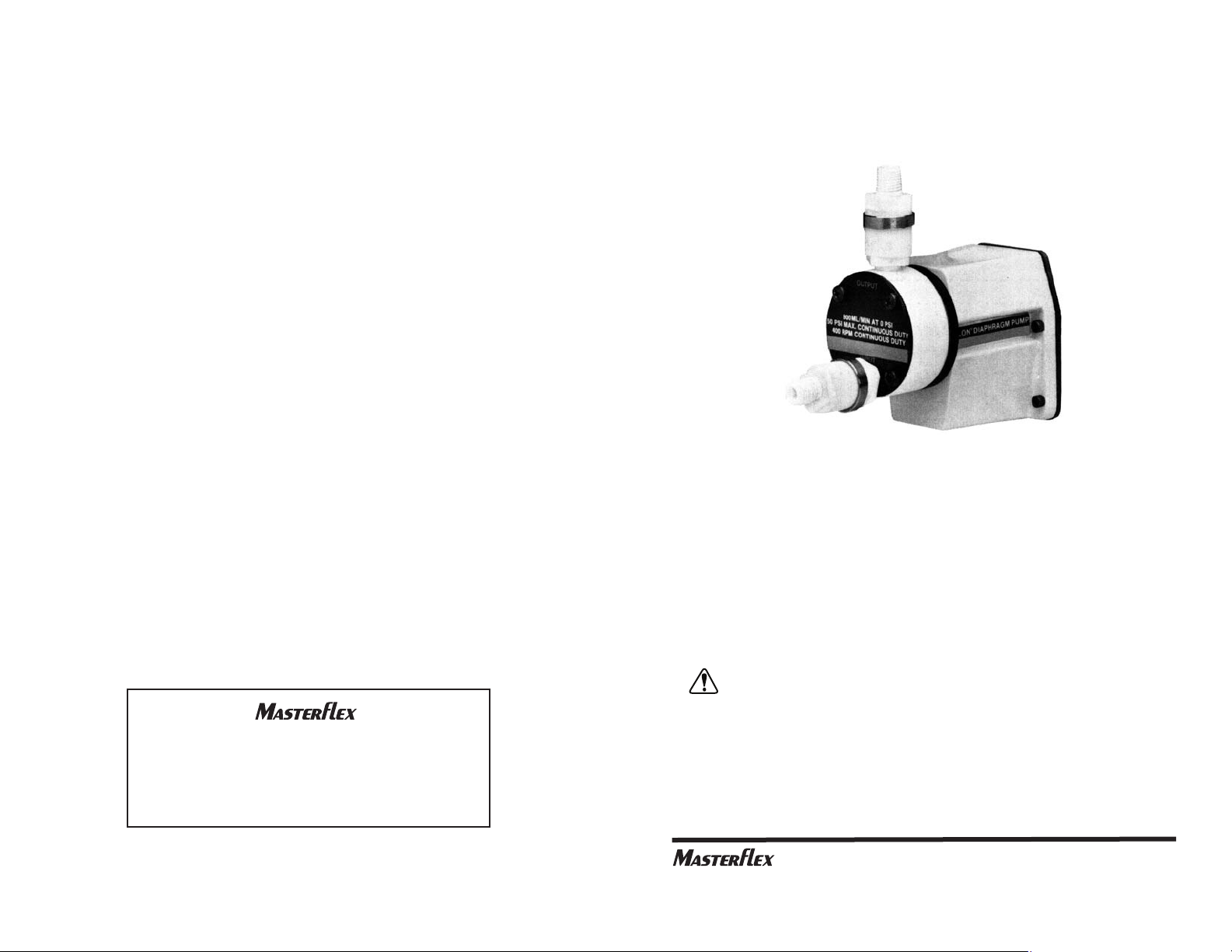
PTFE DIAPHRAGM PUMP
MODEL NO. 07090-42
All wetted surfaces are of PTFE. This heavy-duty, drive-operated pump is
built to deliver virtually any corrosive chemical without harm to its components. Or, the purest fluids can be delivered without risking contamination from the pump. The 07090-42 PTFE Diaphragm Pump handles intermediate size flows (up to 800 mL/min) of a wide range of concentrations
and viscosities. It can also pump fluids through filters and other restrictions, and can pressurize containers.
Flexibility? The PTFE DIAPHRAGM PUMP can be teamed-up with your
existing MASTERFLEX
®
L/S®variable speed drive (10:1) range.
WARNING: THIS PUMP IS CAPABLE OF DEVELOPING PRESSURES IN EXCESS OF
THE MAXIMUM RATED 100 PSIG INTERMITTENT DUTY. APPROPRIATE
PRECAUTIONS SUCH AS A PRESSURE RELIEF VALVE MUST BE
INSTALLED TO PROTECT THE PUMP AND ANCILLARY CONNECTIONS
FROM ACCIDENTAL OVER-PRESSURIZATION.
WARRANTY
The Manufacturer warrants this product to be free from significant deviations from published specifications. If repair or adjustment is necessary
within the warranty period, the problem will be corrected at no charge if it
is not due to misuse or abuse on your part as determined by the
Manufacturer. Repair costs outside the warranty period, or those resulting
from product misuse or abuse, may be invoiced to you.
The warranty period for this product is two (2) years from the date of
purchase.
PRODUCT RETURN
To limit charges and delays, contact the seller or Manufacturer for authorization and shipping instructions before returning the product, either within or outside of the warranty period. When returning the product, please
state the reason for the return. For your protection, pack the product carefully and insure it against possible damage or loss. Any damages resulting
from improper packaging are your responsibility.
TECHNICAL ASSISTANCE
If you have any questions about the use of this product, contact the
Manufacturer or authorized seller.
14
Printed in U.S.A.
(US & Canada only) Toll Free 1-800-MASTERFLEX • 1-800-637-3739
(Outside US & Canada) 1-847-549-7600 • 1-847-381-7050
www.masterflex.com • techinfo@masterflex.com
*EN809 manufactured by:
Cole-Parmer Instrument Company
28W092 Commercial Avenue
Barrington, IL 60010
®
A-1299-0238B
Edition 13
(US & Canada only) Toll Free 1-800-MASTERFLEX ● 1-800-637-3739
(Outside US & Canada) 1-847-549-7600 ● 1-847-381-7050
www.masterflex.com ● techinfo@masterflex.com
®
Page 2
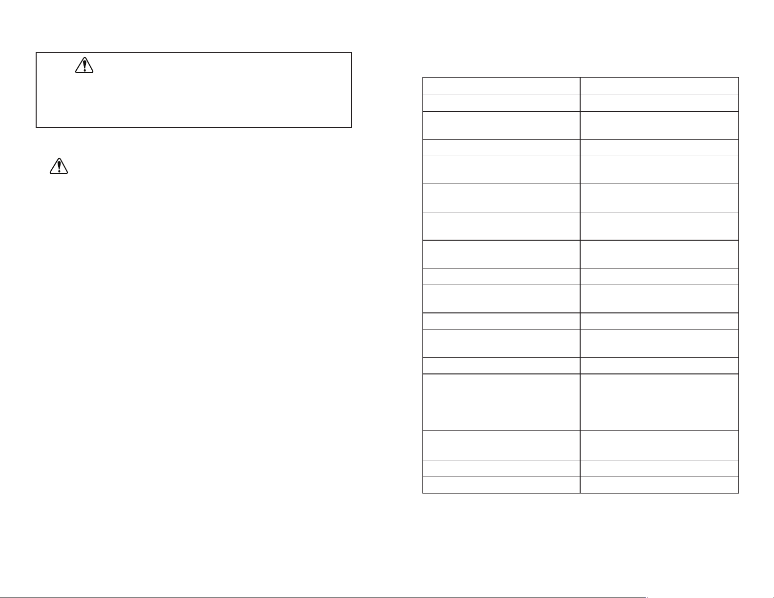
SPECIFICATIONS
PTFE Diaphragm Pump
Model: 07090-42
Flow Rate*: 80 to 800 mL/min
Flow Rate vs. Speed
Conformity Variation: Better than 10% (typical)
Metering Pressure Range: 3 to 50 psig
Max. Rated Pressure: 50 psig (Continuous)
75 psig (Intermittent)
Metering Accuracy: Better than 2% dispensed
volume
Min. Lift: 2 ft (dry)
16 ft (wet)
Pump Head
Dead Volume: 16 mL
Overall Dimensions: 6 in H x 7 in L x 3 in W
Max. Rated Speed: 400 rpm (Continuous)
600 rpm (Intermittent)
Min. Rated Speed: 40 rpm
Operating Fluid: 150° F (Continuous)
Temperature Range: 230° F (Intermittent)
Liquid Viscosity Range: 1 to 500 centipoise
Motor hp at max.
pressure and speed: 1/20 hp
Pump Torque at 0 psig: 2.8 lb-in (AVG)
4.9 lb-in (Peak)
Pump Torque at 5.2 lb-in (AVG)
Max. Pressure: 9.6 lb-in (Peak)
Noise level: <70 dBA @ 1 meter
Compliance (for CE mark): EN809 (EU Machine Directive)
*Performance at 0 psig, 400 rpm, 70°F ambient.
13
SAFETY PRECAUTIONS
WARNING: CHECK VALVES are intended for use on this pump only. Do
not use separately from the pump as forward flow at higher
flow rates will suddenly restrict, causing a rapid increase in
backpressure with resultant hose and connection bursting.
INTRODUCTION
The instructions in this manual are task-oriented for easy reference. You
can go directly to a particular section and quickly find the answers to your
questions. The step-by-step installation and operating instructions are
easy to follow.
Also for easy reference, the component designations used in the illustrations are CAPITALIZED in the text.
i
WARNING: PRODUCT USE LIMITATION
This product is not designed for, nor intended for use in patient
connected applications; including, but not limited to medical
and dental use, and accordingly has not been submitted for
FDA approval.
PUMP FOR LIQUIDS
ORIGINAL INSTRUCTIONS
Page 3
Title Page
SAFETY PRECAUTIONS . . . . . . . . . . . . . . . . . . . . . . . . . . . . . . . . . . . . . i
INTRODUCTION. . . . . . . . . . . . . . . . . . . . . . . . . . . . . . . . . . . . . . . . . . . . i
OPERATING DATA. . . . . . . . . . . . . . . . . . . . . . . . . . . . . . . . . . . . . . . . . . 2
Flow/Pressure Performance . . . . . . . . . . . . . . . . . . . . . . . . . . . . . . . . 2
Chemical Resistance of PTFE . . . . . . . . . . . . . . . . . . . . . . . . . . . . . . 3
Metering/Dispensing Accuracy . . . . . . . . . . . . . . . . . . . . . . . . . . . . . . 3
PUMP CONSTRUCTION. . . . . . . . . . . . . . . . . . . . . . . . . . . . . . . . . . . . . 3
How Drive Mechanism Works. . . . . . . . . . . . . . . . . . . . . . . . . . . . . . . 3
INSTALLATION PROCEDURES . . . . . . . . . . . . . . . . . . . . . . . . . . . . . . . 4
(1) Mount the Pump on Drive . . . . . . . . . . . . . . . . . . . . . . . . . . . . . . . 4
(2) Attach Tubing Fittings . . . . . . . . . . . . . . . . . . . . . . . . . . . . . . . . . . 5
(3) Replacement of Valves . . . . . . . . . . . . . . . . . . . . . . . . . . . . . . . . . 6
(4) Attach Tubing. . . . . . . . . . . . . . . . . . . . . . . . . . . . . . . . . . . . . . . . . 6
(5) Install Filter . . . . . . . . . . . . . . . . . . . . . . . . . . . . . . . . . . . . . . . . . . 6
(6) Adjust Drive Speed . . . . . . . . . . . . . . . . . . . . . . . . . . . . . . . . . . . . 6
(7) Calibrate the Pump (if required) . . . . . . . . . . . . . . . . . . . . . . . . . . 6
TROUBLESHOOTING GUIDE. . . . . . . . . . . . . . . . . . . . . . . . . . . . . . . . . 7
SERVICE PROCEDURES. . . . . . . . . . . . . . . . . . . . . . . . . . . . . . . . . . . . 8
(1) How to Clean the Pump Head. . . . . . . . . . . . . . . . . . . . . . . . . . . . 8
(2) How to Replace Diaphragm . . . . . . . . . . . . . . . . . . . . . . . . . . . . . 9
(3) How to Replace Check Valves . . . . . . . . . . . . . . . . . . . . . . . . . . 11
(4) How to Replace Reagent Head. . . . . . . . . . . . . . . . . . . . . . . . . . 13
ACCESSORIES . . . . . . . . . . . . . . . . . . . . . . . . . . . . . . . . . . . . . . . . . . . 13
SPECIFICATIONS . . . . . . . . . . . . . . . . . . . . . . . . . . . . . . . . . . . . . . . . . 13
WARRANTY. . . . . . . . . . . . . . . . . . . . . . . . . . . . . . . . . . . . . . . . . . . . . . 14
PRODUCT RETURN . . . . . . . . . . . . . . . . . . . . . . . . . . . . . . . . . . . . . . . 14
TECHNICAL ASSISTANCE . . . . . . . . . . . . . . . . . . . . . . . . . . . . . . . . . . 14
Trademarks bearing the ® symbol in this publication
are registered in the U.S. and in other countries.
12
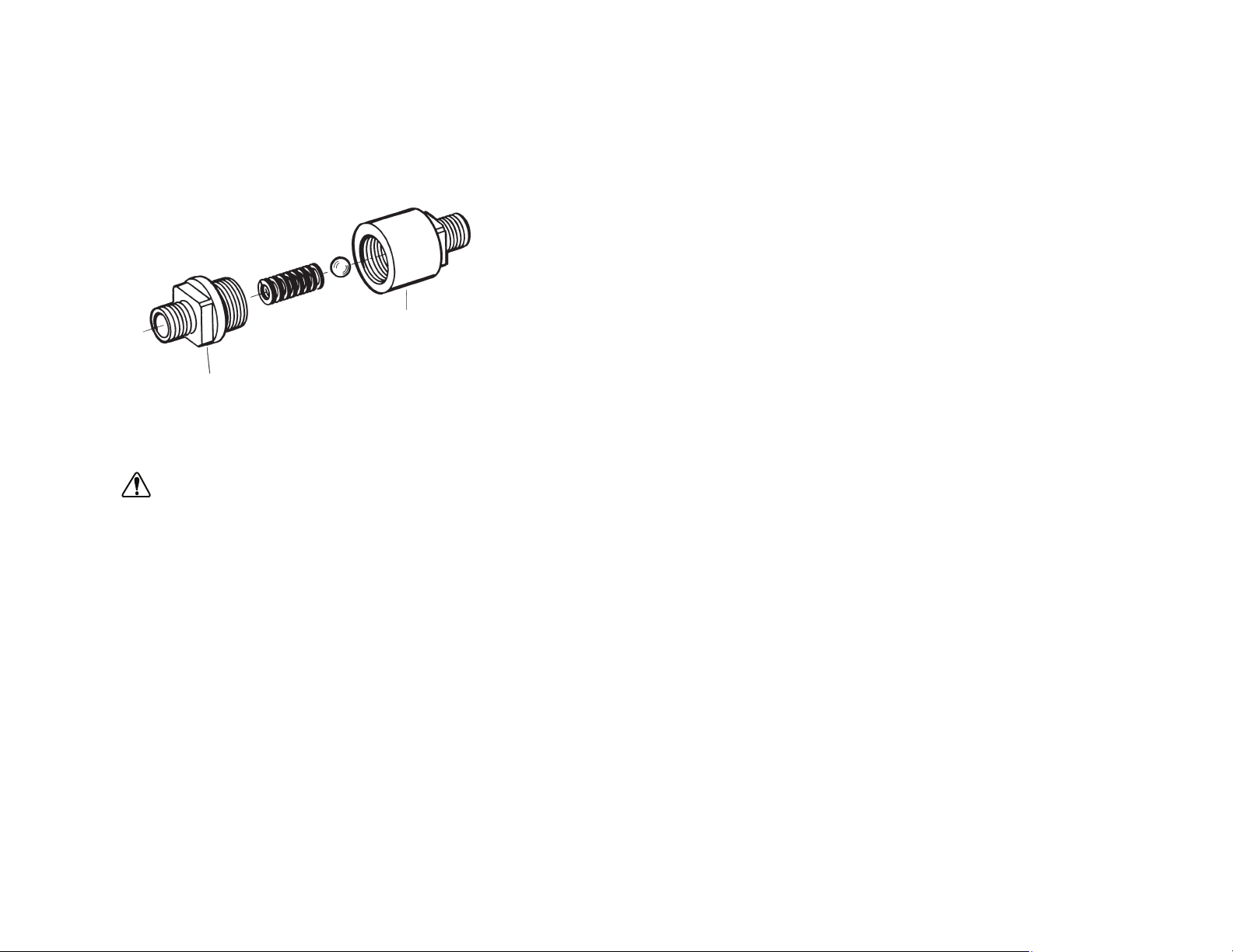
IMPORTANT: It is essential that the inlet end of the CHECK VALVE
be installed in the INLET PORT of the REAGENT HEAD. Similarly,
the outlet end must be installed in the OUTLET PORT.
See Fig. 6 for the correct orientation. The ball seats in the end
shown. When assembled, you can see the ball through the outlet
end of the CHECK VALVE. The pump will not operate unless the
CHECK VALVES are properly installed.
nn To seal, use PTFE tape on threads.
CAUTION: Hand-tighten only. Over-tightening can damage the
PTFE parts.
nn Test the new CHECK VALVE performance by pumping some fluid
under operating conditions.
(4) How to Replace Reagent Head
nn For replacement of the REAGENT HEAD (Part No. D-2027), see
preceding instructions for DIAPHRAGM replacement.
ACCESSORIES
Description Part No.
Female Pipe Adapter with 1/4 NPT
Use with 3/8 in OD tubing 06376-14
PFA Tubing, 3/8 in OD x 1/4 in ID. Pack of 25 ft (7.6 m) 06375-05
External Check Valve 07090-45
Service Kit. Contains PTFE diaphragm, two PTFE 07090-43
check valve assemblies, two drive-tang boots, installation
GAGE/wrench, instructions.
ii
FITS IN INLET
PORT
FITS IN OUTLET
PORT
Figure 6.
TABLE OF CONTENTS
Page 4
nn Using a screwdriver in the slot in the DIAPHRAGM SHAFT and the
7/16 in wrench on the LOCKING NUT, lock the DIAPHRAGM in
place.
nn Recheck to verify that the DIAPHRAGM is at its furthest excursion
and that it just touches the GAGE. If necessary repeat the above
adjustment procedure until the DIAPHRAGM just touches the
GAGE when it is at its furthest excursion.
nn Replace SPACING RING segments.
nn Realign holes in the DIAPHRAGM with holes in the pump housing
by turning the slot in the DIAPHRAGM SHAFT (with a screwdriver)
at back of pump.
nn Attach the REAGENT HEAD to the PUMP BODY.
nn Replace the BACKING PLATE.
nn Tighten the 4 PHILLIPS SCREWS (with washers) uniformly. Make
sure all 4 screws are seated under light torque before tightening
them to specifications (25 pound-inch).
CAUTION: I
f screws are not tightened correctly, the unit will leak
between head and diaphragm. Before placing in service,
test the pump with inert fluid under operating pressure
.
(3) How to Replace Check Valves
The CHECK VALVES can be serviced or replaced individually or in pairs
without disassembly of Pump Head.
WARNINGS: First purge the Pump to flush out any hazardous fluid.
CHECK VALVES are intended for use on this pump only. Do
not use separately from the pump as forward flow at
higher flow rates will suddenly restrict, causing a rapid
increase in backpressure with resultant hose and connection bursting.
nn Unscrew CHECK VALVE from head. Place the wrench (3/4 in)
across the flats adjacent to the threads to be unscrewed. If placed
on the flats farthest from the threads, the valve body halves may
become loose.
Install new CHECK VALVES. Place the wrench (3/4 in) across the
flats adjacent to the threads to be tightened into the Pump. If placed
on the flats farthest from the threads, the Pump halves could
become overstressed and leak under pressure.
11
OPERATING DATA
The Pump delivers fluids at accurately metered flow rates ranging from 80
to 800 mL/min (400 rpm). Intermittent operation up to 1200 mL/min (600
rpm) is permissible. The unit may be run dry—loss of fluid will not harm the
Pump. (See Specifications section for complete details.)
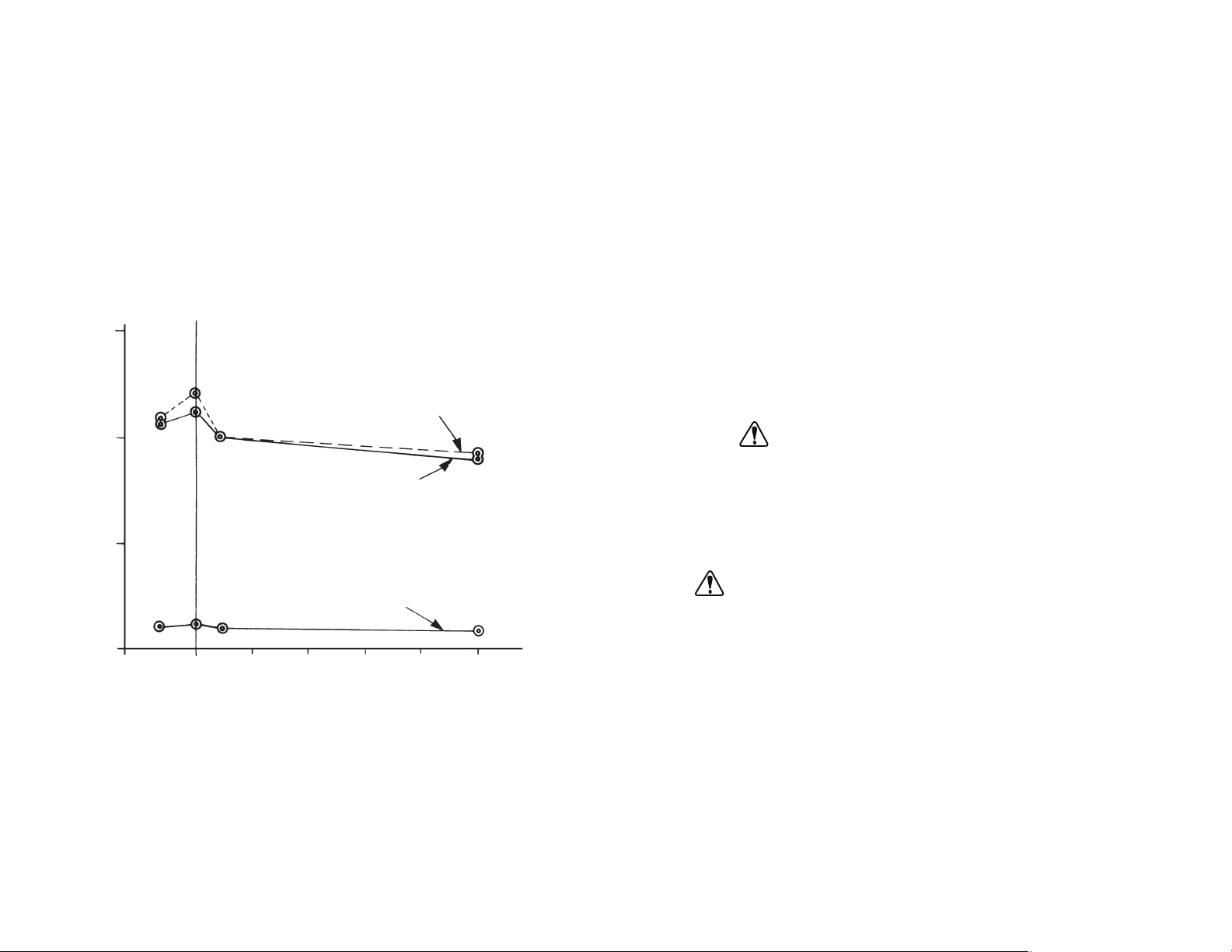
Flow/Pressure Performance
The following graph summarizes pump performance at various speeds,
flows, pressures and viscosities. The DIAPHRAGM can work continuously
against back pressures up to 50 psig (intermittently up to 75 psig) while
providing a wet suction lift of 16 feet of water or more. (Drylift, 24 inches or
more.)
Note the uniform performance at widely varying viscosities. Liquids with
viscosities up to 500 centipoise can also be metered accurately at up to
400 rpm. When pumping very viscous liquids, slight flow rate shifts can be
expected (as compared with water).
2
Figure 1.
EFFECT OF PRESSURE, SPEED AND VISCOSITY ON FLOW
PERCENT RATED FLOW
INLET VACUUM in Hg
400 RPM 1 CENTIPOISE
400 RPM 300 CENTIPOISE
OUTLET VACUUM PSIG
40 RPM 1 & 300 CENTIPOISE
-10 0 10 20 30 40 50
0
50
100
150
Page 5
nn Disconnect Pump Head from Drive by removing 4 SOCKET HEAD-
SCREWS. (See Fig. 2.)
nn Disconnect BACKING PLATE from Pump Head by removing 4
PHILLIPS SCREWS with washers. (See Fig. 4.)
nn With the DIAPHRAGM now loose, remove the SPACING RING seg-
ments. (See Fig. 4.)
nn Remove the REAGENT HEAD (with CHECK VALVES still attached).
NOTE: If a damaged REAGENT HEAD (Part No. D-2072) must be
replaced, also order the complete Service Kit (Part No. 07090-43).
nn To remove the worn DIAPHRAGM, hold a screwdriver in the slot of
the DIAPHRAGM shaft (at back of Pump—see Fig. 2) while simultaneously loosening the LOCKING NUT adjacent to the
DIAPHRAGM. Use a 7/16 in open end wrench.
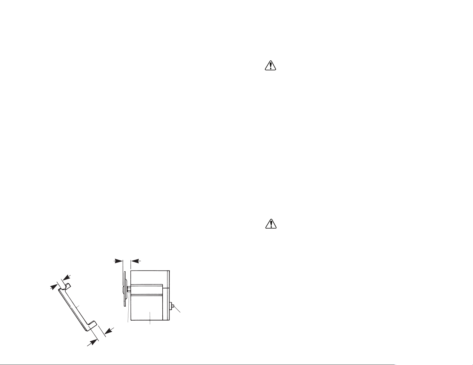
NOTE: A GAGE furnished with the service kit has such a wrench at
one end—see Fig. 5.
nn Loosen diaphragm locknut at shaft using supplied wrench and
remove diaphragm
nn Install 1/4-20 locknut on stud of replacement diaphragm. Locate nut
approximately 1/2" from bottom of stud
nn Install replacement diaphragm into shaft.
nn To obtain maximum durability from the new DIAPHRAGM, and to
prevent it from striking the REAGENT HEAD or the PUMP BODY,
adjust its height correctly by using the GAGE provided. First, while
holding the GAGE against the PUMP BODY, rotate the INPUT
SHAFT (TANG) until the DIAPHRAGM is extended its maximum
distance from the PUMP BODY.
nn Screw the DIAPHRAGM into or out of the DIAPHRAGM SHAFT as
necessary until the letter “B” on the DIAPHRAGM just touches the
GAGE.
Chemical Resistance of PTFE
PTFE has the highest chemical resistance classification (Excellent) for virtually all chemicals—even at high temperatures. For details about resistance and physical properties for specific chemicals consult your dealer.
WARNING: Extended pumping with halogen compounds, including per-
chloric acid, chloroethanol dichlorobenzines, methyl ethyl
ketones, is not recommended and may cause a hazardous
condition.
Metering/Dispensing Accuracy
The 07090-42 Pump delivers fluid with repeatable accuracy of better than
2% volume variation. Best accuracy is achieved under conditions of constant pressure at a preset speed with a fully flooded pump suction. A back
pressure of at least 3 psig assures quick seating of CHECK VALVES and
improves accuracy. For best repeatability, the Pump should be operated
with no suction lift.
PUMP CONSTRUCTION
A rugged cast aluminum housing encloses the unique drive mechanism,
composed of a double convoluted short-stroke PTFE DIAPHRAGM which
flexes in response to a nutating bearing linked to a spring-loaded spool.
The PTFE REAGENT HEAD has INLET/OUTLET PORTS for the CHECK
VALVES, each composed of a PTFE spring-loaded PTFE ball on a PTFE
seat. Body halves will withstand pressures up to 75 psig intermittently.
WARNING: Use a pressure relief valve to prevent higher pressures.
The OUTLET PORT is positioned perpendicular to the DIAPHRAGM axis
to avoid air entrapment, which can affect metering accuracy and cause
reagent contamination. Minimum dead volume improves dispensing accuracy and reduces the amount of liquid trapped in pump.
The gas-purging Pump Head design permits self-priming to a minimum of
24 in of water suction dry lift. Primed wet suction lift is a minimum of 16 feet
of water useful for liquid transfer applications. There’s no need for a separate transfer pump when drawing liquids from the bottom of large tanks.
How Drive Mechanism Works
The drive mechanism is composed of a nutating bearing with a fixed offset
drive coupled to a motor shaft. The bearing rolls against a beveled metal
spool to provide a very efficient and balanced short-stroke drive mechanism. The double convoluted diaphragm (with molded-in stud) flexes with
310
LOCKING
NUT
GAGE
DIAPHRAGM
TANG
PUMP
BODY
Figure 5.
7/16 in
.532
.532
Page 6
each rotation of the nutating bearing, thus pumping fluid at a precise drive
rate. This linear stroking motion imposes very low stress on the
DIA PHRAGM.
NOTE: This drive mechanism never requires lubrication or cleaning.
INSTALLATION PROCEDURES
(1) Mount the Pump On Drive
If your Pump is not already installed on a Drive, follow this procedure:
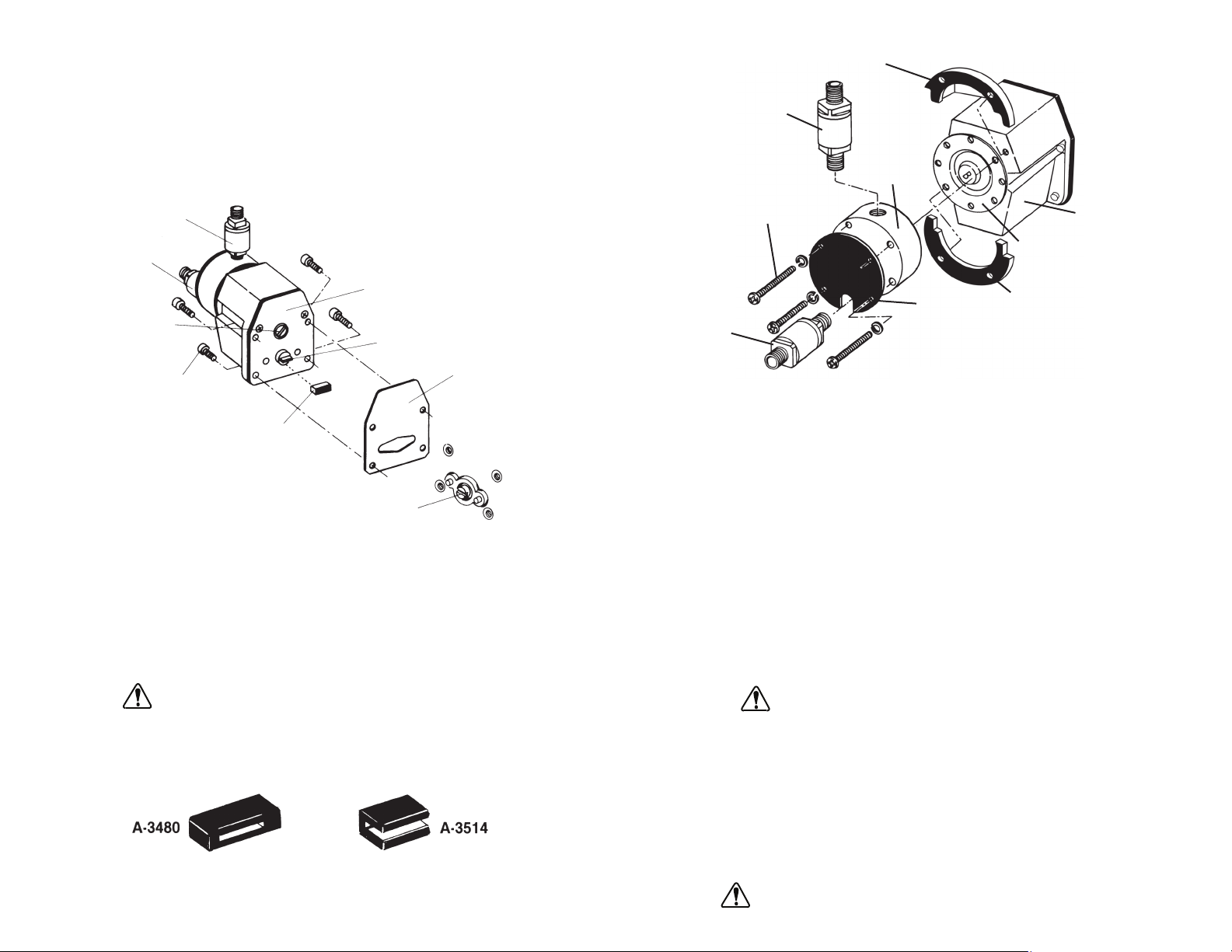
nn Install the plastic BOOT over the TANG at the end of the pump shaft
(Fig. 2). This BOOT should be inspected and replaced when worn
or at 1500 hour intervals.
CAUTION: Not using the BOOT will damage the Pump.
NOTE: The BOOT with closed ends (A-3480) will fit most drives.
Use of the BOOT with open ends (A-3514) may be required on
some drives. Both BOOTS are supplied with the pump.
nn Remove the SPACING RING segments.
nn Remove the REAGENT HEAD, with CHECK VALVES still attached.
nn Clean the surfaces with water or suitable chemicals, depending
upon the fluid previously pumped.
nn Unscrew the CHECK VALVES. Place the wrench across the flats
adjacent to the threads to be unscrewed. If placed on the flats farthest from the threads, the valve body halves may become loose.
Clean the valves. When the valves are reassembled, do not use
more than 7 inch-pounds of torque. Excessive torque may overstress the threads holding the pump halves together, causing leakage when under pressure. To install the valve into the pump, place
the wrench across the flats adjacent to the threads to be screwed
into the pump.
WARNING: Never try to clean the PUMP BODY drive mechanism.
Especially don’t drop it into a solvent. And, repeat, do
not autoclave the unit—this might compromise its inter-
nal lubricating qualities and lead to pump failure.
nn Reassemble all components and connect Pump to the Drive unit.
(2) How to Replace Diaphragm
There’s minimum pump downtime when a damaged or contaminated
DIAPHRAGM must be replaced.
WARNING: Before disassembly, purge the pump. Be sure any haz-
ardous fluid previously pumped is completely flushed out.
94
Figure 3.
SPACING RINGS
PUMP BODY
DIAPHRAGM
BACKING
PLATE
INLET
VALV E
PHILLIPS
SCREWS (4)
OUTLET
VALV E
SPACING
RINGS
REAGENT
HEAD
Figure 4.
Figure 2.
CHECK VALVE
(Outlet)
CHECK VALVE
(Inlet)
BEARING PLATE
TANG
GASKET
SLOT IN DRIVE
MOTOR SHAFT
BOOT
SOCKET HEAD
SCREWS
SLOT IN
DIAPHRAGM
SHAFT
Page 7
nn Connect the Pump to Drive by aligning the TANG on Pump Head
(including installed BOOT) with the SLOT in the motor Drive shaft.
NOTE: It may be easier to turn the shaft on the Drive unit to align
with the Pump Head TANG (using a screwdriver).
nn With the two shafts now connected, fasten the Pump securely to the
Drive unit with the 4 (8-32 x 3/4) SOCKET HEADSCREWS furnished, using the long hex key provided.
(2) Attach Tubing Fittings
Select PTFE fittings (with internal 1/4 NPT thread) required for the
expected backpressure conditions. (Consult your dealer for assistance.)
nn Before attaching tubing fittings to valves, wrap 1 1/2 or 2 1/2 turns
of the 4 mil thick PTFE tape around the 1/4 NPT threads on CHECK
VALVES. This should provide a tight seal.
CAUTION: Don't allow any tape to protrude beyond the end of
threads. Particles could get into CHECK VALVES and
disrupt performance.
nn DO NOT OVER-TIGHTEN PTFE THREADS AND CONNECTIONS.
PTFE has the property of “cold-flowing” when stressed. If over-tightened, PTFE threads will continue to become loose!
CAUTION: It is important to tighten two PTFE parts using the prop-
er wrenches located as close to the joint as practical.
nn Attach tubing fittings to the CHECK VALVES. Place a wrench across
the outer flats (adjacent to the threads) and hold stationary to prevent rotation of valve halves (i.e., valve assembly) relative to each
other. Never allow an already joined part to rotate further than previous joint, when fastening to it.
CAUTION: PTFE threads may strip or PTFE parts may break if
valve body halves rotate relative to each other or if the
valve rotates relative to the head. This will also cause
seal failure of the CHECK VALVE.
nn Tighten your female threaded fitting onto the valve using 60 oz-in
(hand-tighten) of torque.
CAUTION: Exceeding rated torque may strip PTFE threads or
break PTFE parts.
5
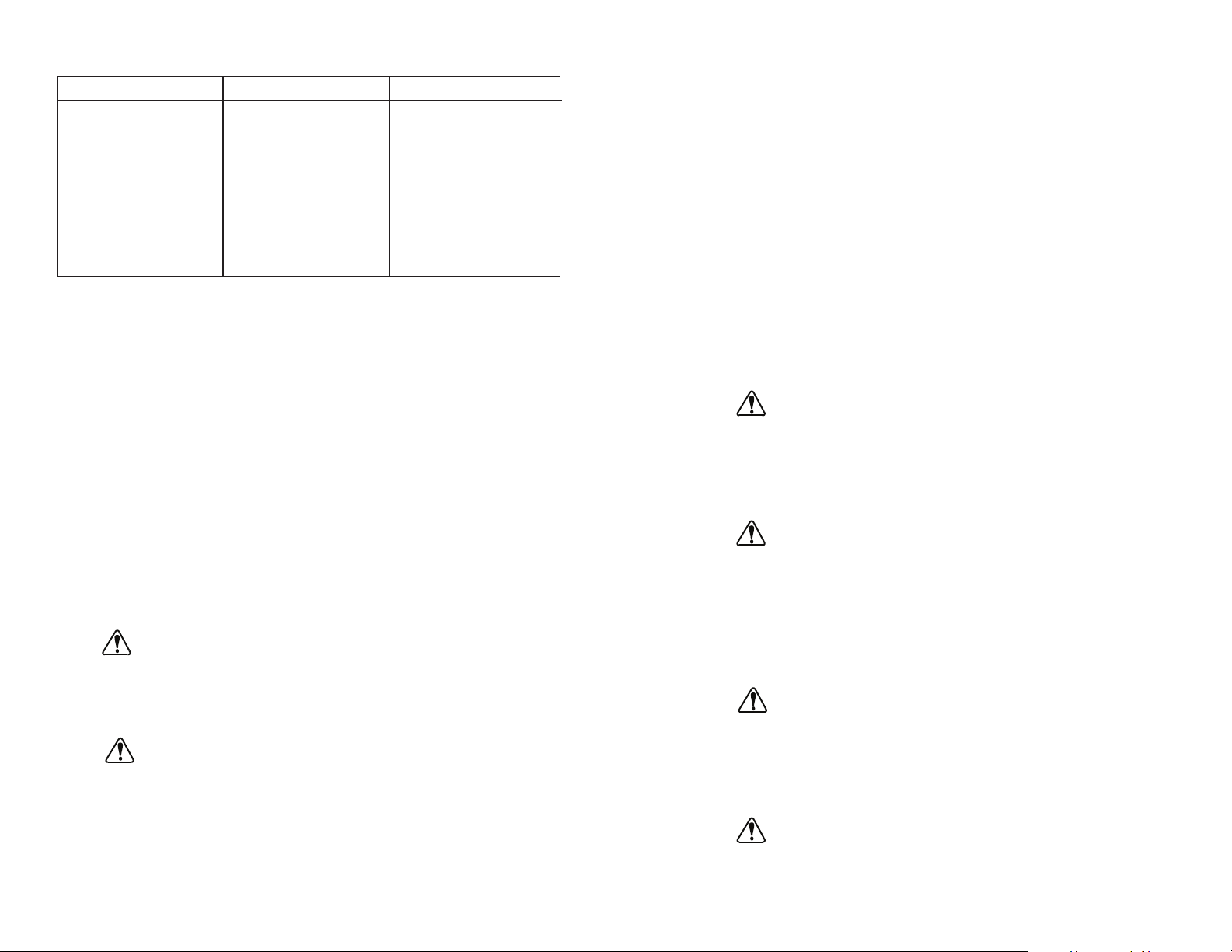
Troubleshooting Solutions (cont.):
Symptom Possible Cause Solution
V REDUCTION IN
FLOW RATE:
1 - Gradually Diaphragm fatigue Replace Diaphragm
& Check Valves
2 - Erratically (a) Dirt in system Clean system
affecting valves Install inlet filter—May
require new Check
Valves
(b) Backpressure Check system
changes plumbing
SERVICE PROCEDURES
The 07090-42 Diaphragm Pump is built for long, hard use, handling the
most corrosive fluids. But if wear problems occur, the DIAPHRAGM,
CHECK VALVES and REAGENT HEAD can be quickly replaced to extend
product life and/or restore flow capacity.
A Service Kit (Part No. 07090-43), ordered separately, contains:
1 DIAPHRAGM (including a GAGE/Wrench to aid in installation)
2 CHECK VALVES
2
Plastic BOOTS for TANG (if ordered separately, use Part No. A-3480
for closed end or Part No. A-3514 for open ends)
.
Following are the most common service procedures:
(1) How to Clean the Pump Head
CAUTION: DO NOT AUTOCLAVE. The use of conventional autoclave
cleaning procedures is not recommended. Consult with
your Dealer if you have special cleaning requirements.
The 07090-42 Pump is easily cleaned because it’s so simple to disassemble the Pump Head after each use.
WARNING: Before disassembly, purge the pump with a suitable fluid.
Be sure any hazardous material previously pumped is
completely flushed out.
nn Disconnect the Pump Head from Drive. Remove 4 SOCKET HEAD-
SCREWS. (See Fig. 2.)
nn Disassemble the Pump Head, (but don’t remove the DIAPHRAGM).
First, disconnect the BACKING PLATE by removing 4 PHILLIPS
SCREWS and washers. (See Fig. 4.)
8
Page 8

TROUBLESHOOTING GUIDE
Symptom Possible Cause Solution
I CLACKING NOISE Tang BOOT worn out Replace BOOT
II FLUID DRIPPING
FROM:
1 - Bottom of Housing Ruptured diaphragm Replace Diaphragm
& Check Valves
2 - Check Valves (a) Loose fittings Remove, retape, install,
hand-tighten
(b) Loose Check Valve Remove, retape, install,
hand-tighten
(c) Check Valve seal Replace valves
failure
(d) Excessive back- Check/reduce
pressure backpressure
3 - Reagent Head (a) Loose screws Tighten screws
(b) Head damage Replace Head
Check Diaphragm for
possible replacement
III BUBBLES IN (a) Fitting leaking Remove, clean and
DISCHARGE LINE tape fittings, reinstall,
torque until tight
(b) Dissolved gases; Increase backpressure
volatilize fluids on pump to stop outgas-
ing or cavitation of fluid.
IV FLUID IS NOT (a) Drive not operating Remove pump &
BEING PUMPED check drive.
Consult drive manual.
(b) Dirt in Check Operate pump at speeds
Valves, or plumb- above 40 rpm. Fill pump
ing problems, or with water and check for
failed Diaphragm, inlet suction. Proper
or failed Drive suction indicates a
mechanism plumbing problem.
No suction indicates a
pump problem: Check for
fluid dripping from housing—which indicates a
Diaphragm failure. If no
dripping, remove Check
Valves, operate pump,
look into ports to see if
Diaphragm is flexing. If
flexing, replace Check
Valves. If not flexing,
the Drive Mechanism has
failed—consult Dealer.
(3) Replacement of Valves
If a valve is to be replaced use a thin 1/2 in open end wrench on the
valve flats closest to the pump to remove the old valve and to install the
new one. Be sure to wrap 2 layers of PTFE tape on the pipe thread.
(4) Attach Tubing
The INLET and OUTLET VALVES on Pump Head are appropriately
labeled.
nn Attach tubing to the inlet and outlet CHECK VALVE fittings.
nn Apply a clamp to secure tubing at each fitting.
WARNINGS: CHECK VALVES are intended for use on this
pump only. Do not use separately from the pump
as forward flow at higher flow rates will suddenly
restrict, causing a rapid increase in backpressure
with resultant hose and connection bursting.
THIS PUMP IS CAPABLE OF DEVELOPING PRESSURES
IN EXCESS OF THE MAXIMUM RATED 100 PSIG INTERMITTENT DUTY. APPROPRIATE PRECAUTIONS SUCH AS
A PRESSURE RELIEF VALVE MUST BE INSTALLED TO
PROTECT THE PUMP AND ANCILLARY CONNECTIONS
FROM ACCIDENTAL OVER-PRESSURIZATION.
(5) Install Filter
Suspended particles in the fluid might cause CHECK VALVE leakage,
resulting in metering inaccuracies. Install a Filter at the pump inlet, if
required.
(6) Adjust Drive Speed
Adjust the variable speed Drive until the required flow rate is achieved.
(Refer to instructions provided with Drive.) Typically, flow will be about
200 mL/min per 100 rpm.
7) Calibrate the Pump (if required)
If best precision is required, each metering session should begin with
a flow calibration procedure. Do this in accordance with anticipated
conditions of speed, temperature and pressure operation.
Allow the pump to run continuously for 5 minutes. This will ensure that
any air drawn into pump during priming has passed through the
DIAPHRAGM HEAD. This warmup period also allows the valves to
properly seal. Also, it stabilizes operating temperatures for the drive
motor and controls. During the first hour of pump/drive operation, minor
warmup considerations may affect metering accuracy.
6 7
 Loading...