

Page 1
Installation & Operations Manual
Master-Bilt Products
908 Highway 15 North
New Albany, MS 38652
Phone: (800) 684-8988
1
PN 071-90000
Rev 03/06/08
Page 2

2
Page 3

TABLE OF CONTENTS
Page Numbers
INTRODUCTION………………………………….……………………………………………………………………4
STORE CONDITIONS / LOCATION..………….…..………………………………………………………………..4
WARNING LABELS AND SAFETY INSTRUCTIONS………..…..……………………………………………… 5
PRE-INSTALLATION INSTRUCTIONS………………………..…..………………………………….…………… 5
Inspection for ShippingDamage……………………………………………………………….…………… 5
INSTALLATION INSTRUCTIONS………………………………………………………………………………….. 6
General Instructions…………………………………………………………………………………………. 6
Thermometer Installation…………………………………………………………………………………….6
CondensateEvaporator...…………………………………………………………………………………….7
Power Toggle Switch…...…………………………………………………………………………………….7
Electrical……..…………………………………………………………………………..…………………….7
STARTING PROCEDURE…………………………………………………………………………………………….7
FINAL CHECK LIST…………………………………………………………………………………….……………..7
LOADING………………………………………………………………………………………………………………..8
CLEANING……………………………………………………………………………………………………………...8
SERVICE INSTRUCTIONS (Trouble Shooting Guide)………………………….……………………………….8
MASTER-BILT PART NUMBERS……………………………………………………………………………………9
ACCESSORIES LIST…………………………………………………………………………………………………10
SERIES Options……...……………………………………………………………………………………………….11
SALE AND DISPOSAL……………………………………………………………………………………………….12
WIRING DIAGRAMS………….…………………………………………………………….…………………… 13-16
3
Page 4
INTRODUCTION
Thank you for purchasing a Master-Bilt cabinet. This manual contains important instructions for installing, using and
servicing a Master-Bilt MPM/QMPM series open air case. Read all these documents carefully before installing or
servicing your equipment. This manual should be left in the care of the store owner or manager.
STORE CONDITIONS / LOCATION
The Master-Bilt MPM/QMPM cases are designed to operate in the controlled environment of an air conditioned
store. The store temperature should be at or below 75°F and a relative humidity of 55% or less. At higher
temperature or humidity conditions, the performance of these cases may be affected and the capacity diminished. It
is not uncommon in a newly constructed store for the temperature and humidity to be above design conditions.
These excessive conditions may produce sweating in the case until the store is operational and the ambient
environment is more desirable.
The Master-Bilt MPM/QMPM should not be positioned where it is directly exposed to rays of the sun or near a direct
source of radiant heat or air flow. No HVAC return or supply air ducts may be located near case openings. This will
adversely affect the case air flow and will result in poor performance. Do not open windows or doors that will affect
the case air flow. The maximum air velocity near the case air return is 50 FPM. If this case is to be located against
a wall there should be at least a 6” space between the wall and the back of the case. The cabinet also requires a
clearance of 10” at the top. This space will allow for the circulation of air behind the case.
These cases should always be loaded properly. This unit will operate differently when loaded or unloaded. Consult
the section of this manual that specifies loading procedures on page 6.
A P-trap is included with each case. It is important that each case has a P-trap installed. Check drain tubing to
insure that it is traped and routed into the condensate pan.
NOTICE
Read this manual before installing your cabinet. Keep the manual and refer to it before doing any service
on the equipment. Failure to do so could result in personal injury or damage to the cabinet.
DANGER
Improper or faulty hook-up of electrical components of the refrigeration units can result in severe injury or
death.
All electrical wiring hook-ups must be done in accordance with all applicable local, regional or national
standards.
NOTICE
Installation and service of the refrigeration and electrical components of the cabinet must be performed by
a refrigeration mechanic and/or a licensed electrician.
The portion of this manual covering refrigeration and electrical components contain technical instructions intended
only for persons qualified to perform refrigeration and electrical work.
This manual cannot cover every installation, use or service situation. If you need additional information, call or write
us:
Customer Service Department
Master-Bilt Products
Highway 15 North
New Albany, MS 38652
Phone (800) 684-8988
Fax (866) 882-7629
4
Page 5
WARNING LABELS AND SAFETY INSTRUCTIONS
This symbol is the safety-alert symbol. When you see this symbol on your cabinet or in
this manual, be alert to the potential for personal injury or damage to your equipment.
Be sure you understand all safety messages and always follow recommended precautions
and safe operating practices.
NOTICE TO EMPLOYERS
You must make sure that everyone who installs, uses or services your cabinet is thoroughly familiar with all
safety information and procedures.
Important safety information is presented in this section and throughout this section and throughout the manual.
The following signal words are used in the warnings and safety messages:
DANGER: Severe injury or death will occur if you ignore the message.
WARNING: Severe injury or death can occur if you ignore the message.
CAUTION: Minor injury or damage to your cabinet can occur if you ignore the message.
NOTICE: This is important installation, operation or service information. If you ignore the
message, you may damage your cabinet.
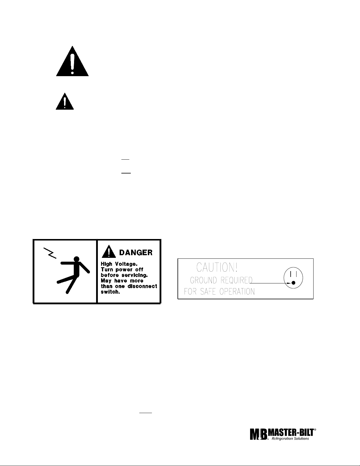
The warning and safety labels shown throughout this manual are placed on your Master-Bilt Products
cabinet at the factory. Follow all warning label instructions. If any warning or safety labels become lost or
damaged, call your customer service department at (601) 534-9061 for replacements.
This label is located on top of the electrical control This label is attached to the cabinet power cord
label and on the wiring channel. on models with a power cord.
PRE-INSTALLATION INSTRUCTIONS
INSPECTION FOR SHIPPING DAMAGE
You are responsible for filing all freight claims with the delivering truck line. Inspect all cartons and crates for
damage as soon as they arrive. If damage is noted to shipping crates or cartons or if a shortage is found, note this
on the bill of lading (all copies) prior to signing.
If damage is discovered when the cabinet is uncrated, immediately call the delivering truck line and follow up the call
with a written report indicating concealed damage to your shipment. Ask for an immediate inspection of your
concealed damage item. Crating material must be retained to show the inspector from the truck line.
5
Page 6

INSTALLATION INSTRUCTIONS
GENERAL INSTRUCTIONS
1. Be sure the equipment is properly installed by competent service people.
2. Keep the equipment clean and sanitary so it will meet your local sanitation codes. Wipe up all spills,clean with
water and a mild detergent, then rinse with clean water. A reservoir is provided to contain interior spills. Peridocially
inspect reservoir and clean as needed.
3. Rotate your stock so that older stock does not accumulate. A "First-In, First-Out" rotation practice will keep the
products in good salable condition.
4. Product should not be put in the case for at least 6 hours after it is started.
5. Stock cases as quickly as possible, exposing only small quantities to store temperatures for short periods of
time.
6. When replacing burned out fluorescent tubes, be sure that the electrical power to the lighting circuit is turned off.
__________________________________________________________________________________
To comply with N.S.F. requirements, this cabinet must be mounted on casters or the base must be sealed to the
floor with NSF listed silicone sealant. Optional casters screw into the holes from which the shipping bolts were
removed. Minimum clearance as follows: 10” air space at top, 6” at the rear, and 0” air space at each side required
for compliance. This space will allow for the circulation of air behind the case which will prevent condensation on the
exterior surfaces.
Before moving cabinet into place, route cabinet plumbing with P-trap to store drain line or install optional condensate
pan.
THERMOMETER INSTALLATION
ANSI/NSF 7, requires that the provided thermometer be installed in the warmest part of the case. Testing has
shown that the sides of the refrigerated space near the load line is the warmest, place see figure 1.1 below.
Remove the tape backing and press the thermometer in place.
SAFE
PRODUCT
LEVEL
FIGURE 1.1
(MPM SHOWN – Typical for QMPM)
6
Page 7

CONDENSATE EVAPORATOR
The MPM/QMPM is designed to operate in an environment of 75° ambient and 55% relative humidity. When the
conditions are applicable for condensation such as high temperature and high humidity, a large capacity condensate
evaporator has been installed in the MPM/QMPM to ensure proper evaporation.
POWER TOGGLE SWITCH
The toggle switch turns the power ON or OFF and is accessible through a slot at the back of the MPM/QMPM-36
and MPM/QMPM-48 cabinet.
NOTICE TO STORE OWNERS / MANAGERS
Moisture or liquid around or under the cabinet is a potential slip/fall hazard for persons walking by or
working in the general area of the cabinet. Any cabinet malfunction or housekeeping problem that creates a
slip/fall hazard around or under the cabinet should be corrected immediately.
If moisture or liquid is observed around or under a Master-Bilt cabinet, an immediate investigation should be made
by qualified personnel to determine the source of the moisture or liquid. The investigation made should determine if
the cabinet is malfunctioning or if there is a drain pipe leaking.
ELECTRICAL
WARNING
Before servicing electrical components in the case make sure all power to case is off. Always use a
qualified technician.
STARTING PROCEDURE
1. Start compressor and allow to run at least 6 hours before placing product into the MPM/QMPM.
DURING THIS TESTING PERIOD YOU SHOULD:
1. Check the temperature holding range against the the control setting.
2. Check the defrost control system to see that all ice is removed from the coil during each defrost cycle.
3. Check pressures.
FINAL CHECK LIST
A. Check setting of defrost timer:
1. Verify setting of four 34 minutes defrost
per 24 hours.
B. Check operating pressures.
C. Check electrical requirements of unit to
supply voltage.
D. Set temperature control for desired
temperature range.
E. Check system for proper defrost operation.
F. Check condensing unit for vibrating or
rubbing tubing. Dampen and clamp as
required.
G. All valves should be completeley open
counter-clockwise.
H. Check packing nuts on all service valves.
I. Replace all service valve caps and latch
unit covers
7
Page 8

LOADING
Do not place product in the case until 6 hours after it is started. Stock cases as quickly as possible, exposing only
small quantities to store temperatures for short periods of time. It is important to keep stock rotated properly so
that older stock does not accumulate. A “First-In, First-Out” rotation practice will keep the products in good salable
condition. Avoid loading the case so that product sticks out beyond the shelves or blocking the return air grille at
the bottom of the case. This will interfere with the air flow of the case and will result in diminished performance.
CLEANING
To avoid electrical shock, turn the power off before cleaning.
The QMVM series cabinets are designed so that spills will accumulate in a drain pan. The drain pan is located
underneath the return air grill. Be sure to clean all areas with a mild detergent and water periodically.
SERVICE INSTRUCTIONS (Trouble Shooting Guide)
1. High head pressure and high back pressure:
A. Condenser coil clogged or restricted.
B. Condenser fan motor defective.
2. Low back pressure and low head pressure:
A. Restriction in system.
B. Refrigerant undercharged.
C. Leak in system.
3. Pressures normal – cabinet warm:
A. Coil blocked with frost or ice (see #4).
B. Control set too warm.
C. Air screen disturbance.
4. Coil blocked with frost or ice:
A. Defective temperature control. E. P-trap in drain not installed.
B. Time clock not operating properly. F. Evaporator fan motor defective.
C. Improper time clock setting. G. Air screen disturbance.
D. Ambient conditions above 75 F/55
5. Compressor starts and runs – but cycles on overload:
A. Low voltage.
B. Dropped phase (3 phase).
C. Overload protector defective.
D. High head pressure (see#1).
E. Relay or Capacitor defective.
6. Compressor will not start – hums, but cycles on overload:
A. Low voltage.
B. Relay defective.
C. Overload protector defective.
D. Start capacitor defective.
E. High head preasure (see #1)
8
Page 9

MASTER-BILT PART NUMBERS
The table below gives Master-Bilt part numbers. Use this chart when ordering replacement parts for your
MPM/QMPM cases.
All quantities are one each unless otherwise noted by parentheses.
Description MPM-36
QMPM-36
Anti-Sweat Heater-Side 17-09121 17-09122 17-09130
Anti-Sweat Heater-Front 17-09119 17-09120 17-09131
Condensate Pan Heater 17-09140 17-09140 17-09140
Condensing Unit 03-14234 01-01474 01-01477
Drier 09-09309 09-09307 09-09185
Evaporator Coil 07-13102 07-13103 07-13106
Evaporator Fan Blade 15-01184 15-01184 15-01184
Evaporator Fan Motor 13-00685 13-00685 13-00685
Expansion Valve 09-09548
Female Plug 21-00577 21-00577 21-00577
Power Cord 21-00312 21-01218
Temperature Control 19-13092 19-13092 19-13092
Timer 19-00819 19-00819 19-00819
Toggle Switch 19-01090 19-01090
MPM-48
QMPM-48
MPM-72
QMPM-72
9
Page 10

ACCESSORIES LIST
QMVM/QMVM-L/QMPM SERIES Bumper Kits
PART NO. DESCRIPTION
SHIP WT.
LB/KG
A071-00100 White bumper for QMPM-36, QMVM-36 and QMVM-36L 5/2
A071-00200 Red bumper for QMPM-36, QMVM-36 and QMVM-36L 5/2
A071-00300 Green bumper for QMPM-36, QMVM-36 and QMVM-36L 5/2
A071-00400 Blue bumper for QMPM-36, QMVM-36 and QMVM-36L 5/2
A071-00500 Brown bumper for QMPM-36, QMVM-36 and QMVM-36L 5/2
A071-00600 Black bumper for QMPM-36, QMVM-36 and QMVM-36L 5/2
A072-00100 White bumper for QMPM-48, QMVM-48 and QMVM-48L 5/2
A072-00200 Red bumper for QMPM-48, QMVM-48 and QMVM-48L 5/2
A072-00300 Green bumper for QMPM-48, QMVM-48 and QMVM-48L 5/2
A072-00400 Blue bumper for QMPM-48, QMVM-48 and QMVM-48L 5/2
A072-00500 Brown bumper for QMPM-48, QMVM-48 and QMVM-48L 5/2
A072-00600 Black bumper for QMPM-48, QMVM-48 and QMVM-48L 5/2
A073-00100 White bumper for QMPM-72 and QMVM-72 5/2
A073-00200 Red bumper for QMPM-72 and QMVM-72 5/2
A073-00300 Green bumper for QMPM-72 and QMVM-72 5/2
BUMPER KITS
A073-00400 Blue bumper for QMPM-72 and QMVM-72 5/2
A073-00500 Brown bumper for QMPM-72 and QMVM-72 5/2
A073-00600 Black bumper for QMPM-72 and QMVM-72 5/2
10
Page 11

MPM/QMPM SERIES Options
PART NO. DESCRIPTION
SHIP
WT.
LB/KG
A075-11140 Set of 4, 3" dia. for QMPM/MPM-36 and QMPM/MPM-48 17/8
A076-11140 Set of 6, 3" dia. for QMPM/MPM-72 26/12
33-01450 16" L for QMPM and MPM models (Max. number of racks per model: -36 size: 2, -48 size: 3, -72 size: 4) 8/4
33-01452 All QMPM and MPM models 1/0.5
A071A11131 For QMPM/MPM-36 10/5
A072A11131 For QMPM/MPM-48 10/5
A073A11131 For QMPM/MPM-72 10/5
A071AB1131 For QMPM/MPM-36 10/5
A072AB1131 For QMPM/MPM-48 10/5
A073AB1131 For QMPM/MPM-72 10/5
CASTERS
SANDWICH RACKS - WELDED WIRE, CHROME PLATED
DIVIDERS FOR SANDWICH RACKS
NIGHT CURTAIN KIT - WHITE (MUST BE FACTORY INSTALLED)
NIGHT CURTAIN KIT - BLACK (MUST BE FACTORY INSTALLED)
A071A11151 For QMPM/MPM-36 15/7
A072A11151 For QMPM/MPM-48 15/7
A073A11151 For QMPM/MPM-72 15/7
A071AB1151 For QMPM/MPM-36 15/7
A072AB1151 For QMPM/MPM-48 15/7
A073AB1151 For QMPM/MPM-72 15/7
A071A11141 For QMPM/MPM-36 15/7
A072A11141 For QMPM/MPM-48 15/7
A073A11141 For QMPM/MPM-72 15/7
A071AB1141 For QMPM/MPM-36 15/7
A072AB1141 For QMPM/MPM-48 15/7
A073AB1141 For QMPM/MPM-72 15/7
LIGHT KIT - WHITE (MUST BE FACTORY INSTALLED)
LIGHT KIT - BLACK (MUST BE FACTORY INSTALLED)
NIGHT CURTAIN & LIGHT KIT - WHITE (MUST BE FACTORY INSTALLED)
NIGHT CURTAIN & LIGHT KIT - BLACK (MUST BE FACTORY INSTALLED)
11
Page 12

SALE AND DISPOSAL
OWNER RESPONSIBILITY
If you sell or give away your Master-Bilt cabinet you must make sure that all safety labels and the Installation Service Manual are included with it. If you need replacement labels or manuals, Master-Bilt will provide them free.
Contact the customer service department at Master-Bilt at (800) 684-8988.
The customer service department at Master-Bilt should be contacted at the time of sale or disposal of your cabinet
so records may be kept of its new location.
If you sell or give away your Master-Bilt cabinet and you evacuate the refrigerant charge before shipment, MasterBilt recommends that the refrigerant charge be properly recovered in complience with section 608 of the Clean Air
Act effective November 1995 and in accordance with all applicable local, regional, or national standards.
12
Page 13

13
Page 14

14
Page 15

15
Page 16

16
 Loading...